Embed Size (px)
Citation preview
1 Copyright © 2003 by ASME
Proceedings of The 2003 ASME International Design Engineering Technical Conferences
and the Computers and Information in Engineering Conference September 2-6, 2003, Chicago, Illinois
DETC2003/DFM-48154
AUTOMATED MANUFACTURABILTY ANALYSIS FOR INJECTION-MOLDED AND DIE-CAST PARTS
Daniel A. McAdams1 Assistant Professor
Rahul A. Bidkar Graduate Research Assistant
Department of Mechanical and Aerospace Engineering And Engineering Mechanics University of Missouri-Rolla
Rolla, MO 65409 1-corresponding author
ABSTRACT
In this article, a mathematical framework to automatically evaluate the manufacturability of injection-molded and die-cast parts is presented. The framework includes both a logical algorithm for the general problem of feature recognition and an implemented mathematical and numerical algorithm to solve key outstanding challenges in feature recognition for manufacturability analysis. A novel feature recognition method is developed that is based on decomposing the part into elemental cubes and then, making use of their individual manufacturability, the manufacturability of the part as a whole is evaluated. This article discusses a procedure to obtain a 3D binary representation of the solid model in a simple fashion and further develops feature recognition techniques to extract critical manufacturability information from this 3D binary array. The outstanding challenges addressed by the method presented include the finding of parting surfaces, undercuts, holes, and bosses in the context of an injection-molded or die-cast part. The algorithm is implemented using a combination of C++ code and Unigraphics solid modeling software. A short example is presented.
KEYWORDS Design for Manufacturing, Feature Recognition, Automated Manufacturability Analysis, Injection-Molding, Die-Casting
INTRODUCTION A smooth integration between design and downstream
applications is crucial for the success of any product. One
approach to join design closer to manufacturing is to develop computer-based tools that indicate the manufacturability of parts during the design stage. Computer based tools that attempt to automate design for manufacturing are a result of considerable research. Automated manufacturability research builds from research in design for manufacturing (DFM), computational geometry, and computer aided design (CAD) and feature recognition.
The majority of successful automated manufacturability analysis research concentrates on machining processes such as milling, drilling, and other material removal based manufacturing processes. Currently, there is little focus on non-machining processes such as injection-molding, die-casting, forging and stamping. Developing methods to enable automated manufacturability analysis for these common and important manufacturing processes is a basic contribution to design for manufacturing. This paper presents a method that evaluates the manufacturability of an injection-molded or a die-cast part.
The next section presents a background on design for manufacturing and computer aided design along with a literature survey in the area of feature recognition for manufacturability analysis. The next section discusses the need for a new feature recognition technique that can solve the problem of automated manufacturability analysis of injection-molded and die-cast parts. Following that, there is a discussion of the central contribution of this article, the manufacturability evaluation algorithm (MEA). How the MEA evaluates the manufacturability of parts is discussed next. At this point, examples to demonstrate how the MEA determines the parting surface of the part and the undercuts are provided. Also, examples are presented to demonstrate recognition of bosses

2 Copyright © 2003 by ASME
and holes in a part. Lastly, there is brief discussion of implementation, future work and conclusions.
RELATED WORK “Economic manufacturing does not just happen. It starts
with design and considers the practical limits of machine tools, processes, tolerances, and finishes.” This quote from Trucks (1987) articulates the role that DFM has to play in the design of any part. Manufacturability of a part can be specified either qualitatively or it can be quantified. A preferred manufacturability assessment is the one that quantifies the manufacturability in terms of the time and cost of the manufacturing processes involved. The research in this article is based on a manufacturability assessment that includes cost estimates for the part being designed.
DFM methods may be applied to four stages of the design process (Mill et al., 1994) the conceptual stage, the assembly stage, selection of materials, processes, and the detailed or parametric design stage. The work presented in this article is for implementation during configuration and parametric stages of design. Vliet et al. (1999) have reported state of the art techniques in DFM. A comprehensive survey of various manufacturability evaluation approaches can be found in the work of Gupta et al. (1997).
DFM is a broad term with many areas of emphasis. Two important areas are DFM for machining processes and DFM for non-machining processes such as injection-molding, die-casting and stamping. DFM in the context of machining is dealt with in several different manners (Priest et al., 1991; Gupta et al., 1995). Feature-based manufacturing (Shah et al. 1994) uses features to bridge the gap between design and other downstream applications. Features are “chunks of knowledge” that represent the engineering meaning or significance of the geometry of a part (Shah et al., 1995).
Using a feature based approach, the evaluation of part manufacturability at the configuration and parametric design stages has been dealt with in the monograph by Dixon and Poli (1995). Poli et al. (1988; 1990) and Dastidar (1991) discuss how the presence and location of holes, projections, and other features affect the tooling and processing cost for injection-molding, die-casting, and stamping.
Geometric modeling (Mortenson, 1985) and computer aided design (Zeid, 1991) play a crucial role in part design. Early computer aided design (CAD) systems were primarily drafting systems. Even though there is still debate whether CAD, as commonly practiced, is much more than sophisticated drafting, current solid modeling systems enable more sophisticated manufacturability analysis than in the past. Nevertheless, the solid model of a part suffers from some deficiencies with respect to DFM. CAD data is stored as a boundary representation (B-rep) model. Such models contain low-level data like points, edges, curves, and faces. Entities needed for manufacturability assessment such as bosses, holes, distance between holes, and sheet thickness are not explicitly available in B-rep models. The need for extraction of such
information from the computer based mathematical representations of the part leads us into the area of feature modeling. Feature modeling is used to capture the design intent of features (Shah et al., 1995) with the intention of providing improvements to ordinary geometric modeling techniques. Identifying features from the solid model of a part then becomes a vital step in automated manufacturability analysis. This step is commonly referred to in the literature as feature recognition.
Recognizing part features from a solid model has been the area of active research for at least the past 18 years. But still a comprehensive technique for feature recognition is missing. The literature on feature recognition mainly focuses on applications related to manufacturing processes in the machining domain. Research into feature recognition for non-machining processes has received less effort. A prominent characteristic of the research presented in this article is that it investigates the applicability of both existing and new feature recognition techniques to the manufacturability evaluation of injection-molded and die-cast parts.
Many feature recognition techniques focus on process planning, tool path generation, and NC part programming. Henderson et al. (1994) have surveyed the various feature identification techniques used to extract features from B-reps of parts. The rule based approaches (Kyprianou, 1980; Henderson, 1984; Vandenbrande, 1990) use artificial intelligence techniques to develop a set of feature rules. The drawback of this approach is that rules tend to be specific to a set of features. In addition, rule-based algorithms tend to be slow because of the enormous amount of geometric data that they must scan through. Some of the problems of slow speed have been addressed by the use of a differential depth filter (Gadh et al., 1992).
Another successful feature recognition technique is the graph-based approach (Joshi et al., 1988; Sakurai et al., 1988). This approach consists of representing the topological information of the B-rep model of a part using graph theory. This graph representation of the solid model is divided into sub graphs. If any sub graph matches with a feature graph, a feature is found. The drawback of this approach is that interacting features tend to confuse these algorithms.
Many other approaches to feature recognition have been tried with different ranges of applicability and degrees of success. Neural networks have been applied to the problem of feature recognition in the work of Prabhakar (1990). Woo (1982) developed the alternating sum of volumes approach in his pioneering work in the field of feature recognition. The non-convergence of Woo’s algorithm for certain geometries was investigated by Yong Se Kim (1994) who then presented a refined algorithm. Kramer et al. (1993) created a library of material removal shape element volumes (MRSEVs). Regli et al. (1993; 1994; 1995) solved the problem of taking a CAD model and extracting machinable features that contain the complete set of alternative interpretations of the part as collection of MRSEVs. The delta volume is thus decomposed
3 Copyright © 2003 by ASME
into MRSEVs and this database is used to evaluate the manufacturability in the context of machining.
Vandenbrande (1990) gives a powerful method of feature recognition in which rules and procedures manipulate the data and generate hints for the presence of machining features. Promising hints are further processed to complete the feature volumes and later checked for their machinability. Requicha et al. (1998) describe an Integrated Incremental Feature Finder that works, in a four-step approach: hint, generate, test, and, repair. This approach is able to recognize three types of features: holes, slots, and pockets. Gadh (1994) discusses an innovative method for creating the design using preset features with the aim of later utilizing them to perform manufacturability analysis.
Lei et al. (2000) present a novel procedure for extraction of form features from the CAD model of a part. This approach of digitizing the solid model of a part and using wavelet transforms, although somewhat similar in nature to the research presented here, does not address injection-molded and die-cast parts. The differences and similarities between the current approach developed here and work of Lei will be pointed out later in this paper.
From a review of current and past efforts, the following conclusions can be drawn.
• Automated manufacturability analysis is done primarily in the context of machining processes such as milling, drilling and other material removal processes. It is not done in the context of non-material removal processes such as die-casting or injection- molding.
• Feature recognition is done primarily with the aim of carrying out Computer aided Process Planning and NC tool path generation.
There has been little effort toward automatic feature recognition as needed by the non-material removal manufacturing processes of injection-molding, die-casting and stamping. Thus, a key focus of this work is to begin the research that will enable feature recognition and automated manufacturability analysis to be applied to these important manufacturing processes.
FEATURE RECOGNITION FOR INJECTION-MOLDING AND DIE-CASTING
One of the initial and critical needs for developing design for manufacturability assessment is to develop knowledge of what can and cannot be manufactured. The initial representation for this manufacturing capability is generally stored in the manufacturing engineer’s experience. Traditionally, through collaboration with design and manufacturing engineers, the possibility and cost of producing some part is determined.
Our approach to developing an automated manufacturability evaluation tool builds on the manufacturability knowledge cataloged by Dixon and Poli (Dixon et al., 1995; Poli, 1988; Poli, 1990; Poli, 2001). Dixon
and Poli have determined the characteristics of parts that determine part manufacturability and cost. They have reduced the manufacturing engineer’s knowledge of injection-molding and die-casting to a set of part features and feature characteristics. We begin our efforts building on this knowledge.
Building on the efforts of Dixon and Poli, two immediate tasks for automated manufacturability analysis of injection-molded and die-cast parts are apparent. The first is to decompose the manufacturability guidelines from Dixon and Poli into a structured algorithm that can be coded for automation. This algorithm will require input that contains information about part features. The second task is to develop a feature recognition algorithm that will enable a computer to recognize features and feed them as input to the structured algorithm.
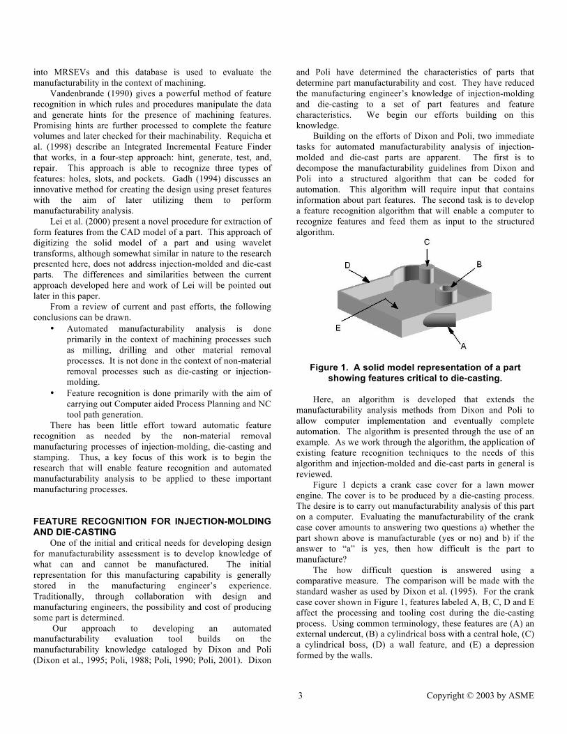
Figure 1. A solid model representation of a part showing features critical to die-casting.
Here, an algorithm is developed that extends the
manufacturability analysis methods from Dixon and Poli to allow computer implementation and eventually complete automation. The algorithm is presented through the use of an example. As we work through the algorithm, the application of existing feature recognition techniques to the needs of this algorithm and injection-molded and die-cast parts in general is reviewed.
Figure 1 depicts a crank case cover for a lawn mower engine. The cover is to be produced by a die-casting process. The desire is to carry out manufacturability analysis of this part on a computer. Evaluating the manufacturability of the crank case cover amounts to answering two questions a) whether the part shown above is manufacturable (yes or no) and b) if the answer to “a” is yes, then how difficult is the part to manufacture?
The how difficult question is answered using a comparative measure. The comparison will be made with the standard washer as used by Dixon et al. (1995). For the crank case cover shown in Figure 1, features labeled A, B, C, D and E affect the processing and tooling cost during the die-casting process. Using common terminology, these features are (A) an external undercut, (B) a cylindrical boss with a central hole, (C) a cylindrical boss, (D) a wall feature, and (E) a depression formed by the walls.

4 Copyright © 2003 by ASME
Figure 2. A flow chart showing the primary steps of
the Global manufacturability analysis algorithm.
The manufacturability guidelines from Dixon and Poli (1995) are decomposed to produce a manufacturability analysis algorithm. Structuring the guidelines in such a manner not only facilitates automation, but also clarifies the specific feature recognition needs of injection-molding and die-casting. Shown in Figure 2 is the global algorithm for determining manufacturability. Each step of the global algorithm will be further subdivided into a separate feature recognition algorithm. In this global algorithm, a shaded box means that to answer the question, feature recognition is needed.
Figure 3. A detailed algorithm to determine whether a part is flat or box shaped. Step AA for the global
manufacturability analysis algorithm. For example, to complete step AA, a determination of
whether the part is flat or box shaped needs to be made. Figure 3 shows the expanded algorithm required at step AA. Moving through the algorithm in Figure 3, questions concerning the presence and characteristics of features need to be answered. In the context of part shown in Figure 1, the feature labeled A is a boundary feature and it should be recognized and given as an input to the algorithm in Figure 3. Similar expanded algorithms for each of the steps AA, BB, CC, DD and EE in the global algorithm of Figure 2 have been developed. These expanded algorithms are found in the appendix.
Continuing through the example, an important factor that drives the cost of injection-molded and die-cast parts is the number of undercuts present in the part. The feature labeled A in Figure 1 is an external undercut. The feature recognition technique needs to recognize this fact. While calculating the basic complexity for step DD in the global algorithm, the algorithm should not only know the number and location of undercuts, but also should identify the mold parting surface. The term basic complexity in step DD of Figure 2 accounts for the number of undercuts a part contains. A greater number of undercuts in a part results in a greater part complexity.
5 Copyright © 2003 by ASME
The subsidiary complexity is calculated in step EE of the global algorithm. The term subsidiary complexity in step EE of Figure 2 is used to quantify the die-cavity detail required to manufacture the part (Dixon et al., 1995). To determine the subsidiary complexity, the presence and characteristics of holes, bosses, ribs, and walls needs to be determined. Once answers to all the questions in steps AA through EE can be determined, the manufacturability of the part can be determined in terms of its relative manufacturing cost as compared to a standard washer (Dixon et al., 1995).
One of the most important results of developing these manufacturability analysis algorithms is that the critical feature recognition needs for injection-molding and die-casting are identified. Also, key characteristics of recognized features that need to be known are identified. Both recognition of features and determining key characteristics of these features will be referred to as “feature recognition problems” from here forward.
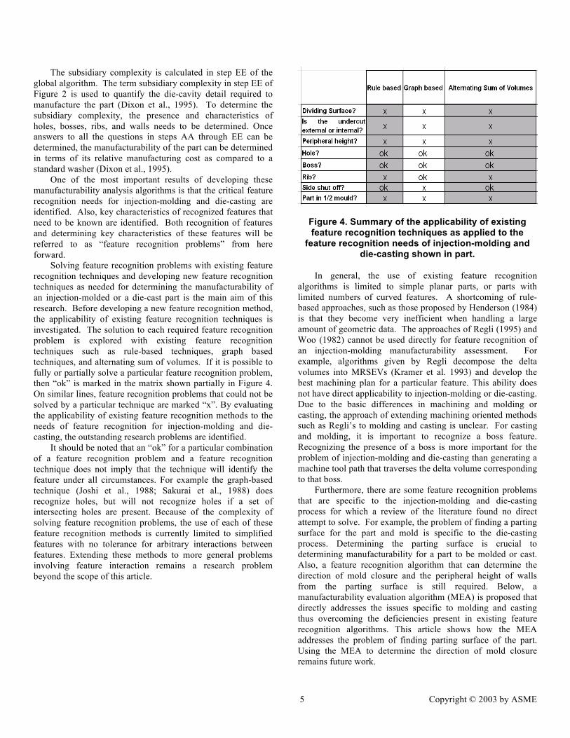
Solving feature recognition problems with existing feature recognition techniques and developing new feature recognition techniques as needed for determining the manufacturability of an injection-molded or a die-cast part is the main aim of this research. Before developing a new feature recognition method, the applicability of existing feature recognition techniques is investigated. The solution to each required feature recognition problem is explored with existing feature recognition techniques such as rule-based techniques, graph based techniques, and alternating sum of volumes. If it is possible to fully or partially solve a particular feature recognition problem, then “ok” is marked in the matrix shown partially in Figure 4. On similar lines, feature recognition problems that could not be solved by a particular technique are marked “x”. By evaluating the applicability of existing feature recognition methods to the needs of feature recognition for injection-molding and die-casting, the outstanding research problems are identified.
It should be noted that an “ok” for a particular combination of a feature recognition problem and a feature recognition technique does not imply that the technique will identify the feature under all circumstances. For example the graph-based technique (Joshi et al., 1988; Sakurai et al., 1988) does recognize holes, but will not recognize holes if a set of intersecting holes are present. Because of the complexity of solving feature recognition problems, the use of each of these feature recognition methods is currently limited to simplified features with no tolerance for arbitrary interactions between features. Extending these methods to more general problems involving feature interaction remains a research problem beyond the scope of this article.
Figure 4. Summary of the applicability of existing feature recognition techniques as applied to the
feature recognition needs of injection-molding and die-casting shown in part.
In general, the use of existing feature recognition
algorithms is limited to simple planar parts, or parts with limited numbers of curved features. A shortcoming of rule-based approaches, such as those proposed by Henderson (1984) is that they become very inefficient when handling a large amount of geometric data. The approaches of Regli (1995) and Woo (1982) cannot be used directly for feature recognition of an injection-molding manufacturability assessment. For example, algorithms given by Regli decompose the delta volumes into MRSEVs (Kramer et al. 1993) and develop the best machining plan for a particular feature. This ability does not have direct applicability to injection-molding or die-casting. Due to the basic differences in machining and molding or casting, the approach of extending machining oriented methods such as Regli’s to molding and casting is unclear. For casting and molding, it is important to recognize a boss feature. Recognizing the presence of a boss is more important for the problem of injection-molding and die-casting than generating a machine tool path that traverses the delta volume corresponding to that boss.
Furthermore, there are some feature recognition problems that are specific to the injection-molding and die-casting process for which a review of the literature found no direct attempt to solve. For example, the problem of finding a parting surface for the part and mold is specific to the die-casting process. Determining the parting surface is crucial to determining manufacturability for a part to be molded or cast. Also, a feature recognition algorithm that can determine the direction of mold closure and the peripheral height of walls from the parting surface is still required. Below, a manufacturability evaluation algorithm (MEA) is proposed that directly addresses the issues specific to molding and casting thus overcoming the deficiencies present in existing feature recognition algorithms. This article shows how the MEA addresses the problem of finding parting surface of the part. Using the MEA to determine the direction of mold closure remains future work.

6 Copyright © 2003 by ASME
A MANUFACTURABILTY EVALUATION ALGORITHM FOR INJECTION-MOLDING AND DIE-CASTING
In this section, a method is developed to perform feature recognition that will enable automated manufacturability evaluation for injection-molding and die-casting. The method is extended to a quantified algorithm and the associated computer code is used to explore a simple example. The underlying philosophy and approach of this algorithm builds upon both the characterization of injection-molded and die-cast parts as found in Dixon and Poli (Dixon et al., 1995) and the fundamental physical nature of molding and casting processes. The fundamental physical notion used to inspire this algorithm is that each surface of the part must come into contact with the mold. Thus, the interaction of solids and voids (from the part’s perspective) leads to a basic understanding of what can and cannot be molded or cast. Motivation for building upon the work of Dixon and Poli is based on the wealth of manufacturability knowledge already partially codified by their efforts.
The first step of the method is to represent the solid model of the part in terms of a 3D binary array of 1s and 0s. The basic aim of this algorithm is to rebuild the solid model of a part in terms of solid cubes represented by 1s and void cubes represented by 0s. Representing the solid model of the part in this fashion has key advantages for determining molding manufacturability. These advantages are elaborated below.
Figure 5. A simple part to be molded.
Part Representation: Solid Cubes and Void Cubes In injection-molding and die-casting, a surface of a part is
produced by allowing the polymer or molten metal to cool against the walls of the mold. For example, consider a cube shaped part as shown in Figure 5.
This part has six faces. If this part is to be produced by die-casting, its surfaces will be formed by the surfaces of the mold. In the case of part shown in Figure 5, surface A will be produced because a corresponding surface is present in the mold. Surface A of the cube can and will be produced only if the corresponding surface of the mold can reach the surface A.
Consider that one vertex of the part shown in Figure 5 is placed at the origin (x = 0, y = 0, z = 0). In general, the part geometry in Figure 5 is manufacturable either by molding or casting. Physically, the reason behind this is that the six surfaces of the mold can come into contact with all six faces of this part. Simply put, if the surface of the mold can move towards the part starting from infinity and ending on the part, at no point will the mold path experience an obstacle of any kind.
A necessary condition for a part to be manufactured is that there is no obstacle, or a solid cube, between the surface A that is to be produced and the mold surface that will produce it. If another solid cube (physically, an obstacle) is present between the two, then surface A of the part is not manufacturable. By decomposing a part into a 3D array of solid cubes and void cubes, the relationship between solid and void cubes is used to determine manufacturability.
Figure 6. A candidate part decomposed into small building blocks.
Continuing with the cubic part shown in Figure 6, the part
is decomposed into 27 building blocks. The solid cube building blocks (1s) are classified into two categories.
1. Type I: The building block solid cubes that lie completely inside the part. These are surrounded on all six sides by other solid cubes.
2. Type II: The building block solid cubes that are surrounded by other solid cubes on less than six sides and exposed on the remaining sides.
Type I solid cubes signify a location in the part where the molten liquid metal or the polymer flows and they do not directly affect the manufacturability. In terms of the decomposed part, only solid cubes of the Type II “get manufactured.” Type II cubes come in contact with the surface of the mold. Type II cubes form the boundary of the part and thus are critical to determining part manufacturability.
As an example consider the block with a cylindrical boss as shown in Figure 7. The cylindrical boss has a central hole. The MEA represents the inner surface of the hole by solid cubes of Type II. Using the direction of mold closure as given in Figure 7, the Type II cubes that form the inner surface of the hole cannot be manufactured, thus the hole is a non-manufacturable feature. The hole in Figure 7 could be manufactured by a side-action mold closing. Such side-action mold closure increases the cost of manufacturing the part and the hole that needs to be side-manufactured gets classified as an

7 Copyright © 2003 by ASME
undercut. Though the methods presented here extend directly to determining side action molded features, doing so remains future work.
Figure 7. A simple part with a hollow boss.
Based on a binary representation, the basic aim of the MEA is to represent the solid model of a part in terms of cubes of Type I and Type II and to evaluate the manufacturability (or accessibility) of every solid cube of Type II.
If every Type II solid cube found in the model is manufacturable, the part is manufacturable by die-casting and injection-molding. If cubes of Type II are not accessible for the given direction of mold closure, the part as a whole cannot be injection-molded or die-cast. By representing the solid model of a part in terms of solid cubes and void cubes, the evaluation of manufacturability of the whole part is reduced to considering the manufacturability of individual cubes. In addition to determining the manufacturability of the part, individual cubes will be used below to determine both the parting surface and the presence of hole and boss features. The binary representation allows feature recognition without processing geometric data in the form of points, edges, and faces. A discussion on obtaining the binary representation is given next.
Obtaining the binary representation One of the strengths of the feature recognition technique
developed in this article is the simplicity of obtaining a binary representation of the solid model. Here the aim is to decompose and rebuild the part in terms of cubes of height h.
Figure 8. A block with a cylindrical boss The size of the cubes that become the building blocks
affects the ability of the MEA to identify features. A smaller size elemental cube allows a smaller feature to be identified. However, a smaller size cube requires increased computational time and cost. The largest viable value for h is dictated by the size of the smallest feature that the MEA needs to recognize. In this article, a cube size of h = 1mm x 1mm x 1mm was taken for test parts of approximate size 70 mm x 40 mm x 20 mm.
Figure 9. The sliced version of the part With h determined, the solid model of the part is sliced.
Three orthogonal slices are made through the solid to reduce the solid to a three dimensional mesh. The implementation of the meshing is shown in Figures 8 and 9. Solid and void cubes (1s and 0s) are obtained by Boolean algebra. If a cube is more than 50% solid, it is considered solid and marked a 1, otherwise it is marked a 0. This procedure is used to obtain a binary representation for the entire part.
Type classification of solid cubes The binary data developed above will be used for solving
feature recognition problems. Before using this data to find the parting surface or recognize holes and bosses, the solid cubes are classified as Type I or Type II cubes. The classification is done by gathering the neighborhood information for all the solid and void cubes. For example, the binary representation for a rectangular slice with a rectangular hole is shown in Figure 10.
8 Copyright © 2003 by ASME
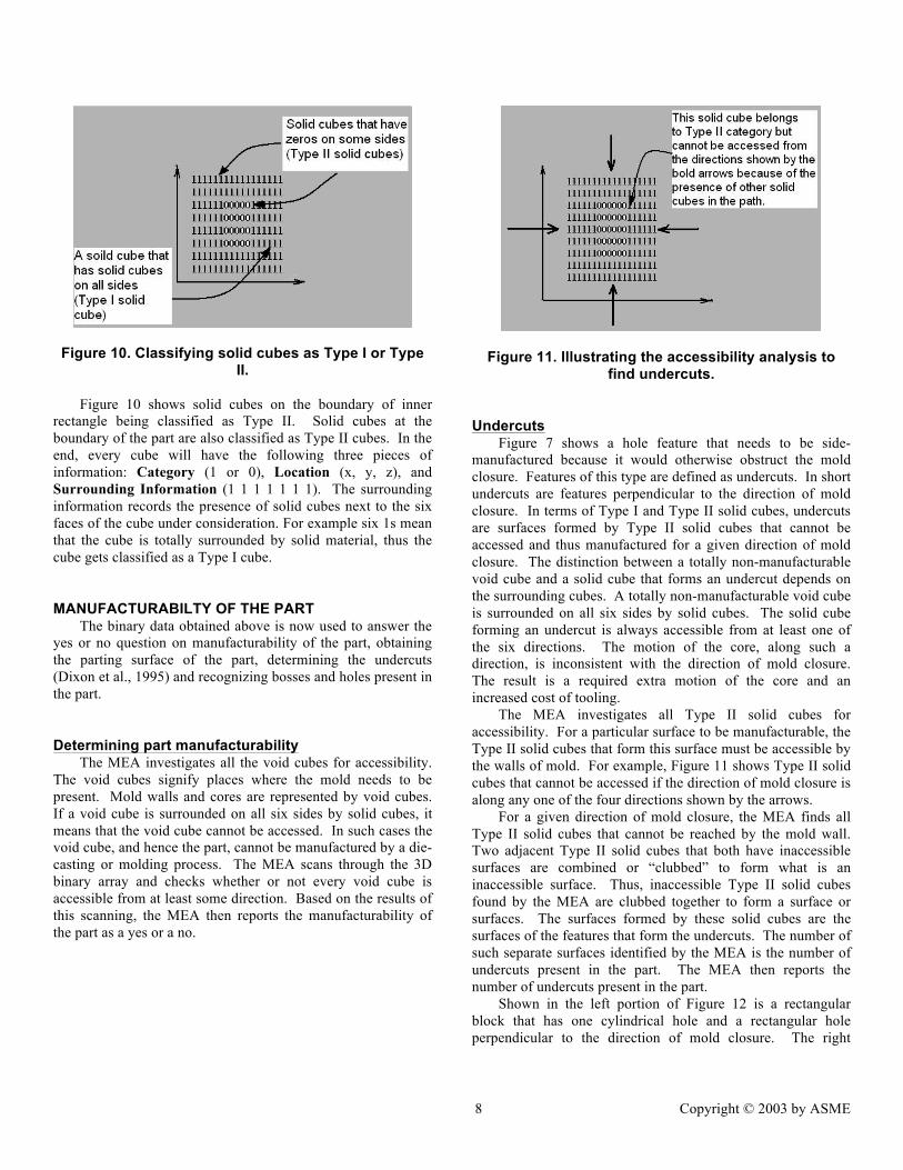
Figure 10. Classifying solid cubes as Type I or Type II.
Figure 10 shows solid cubes on the boundary of inner
rectangle being classified as Type II. Solid cubes at the boundary of the part are also classified as Type II cubes. In the end, every cube will have the following three pieces of information: Category (1 or 0), Location (x, y, z), and Surrounding Information (1 1 1 1 1 1 1). The surrounding information records the presence of solid cubes next to the six faces of the cube under consideration. For example six 1s mean that the cube is totally surrounded by solid material, thus the cube gets classified as a Type I cube.
MANUFACTURABILTY OF THE PART The binary data obtained above is now used to answer the
yes or no question on manufacturability of the part, obtaining the parting surface of the part, determining the undercuts (Dixon et al., 1995) and recognizing bosses and holes present in the part.
Determining part manufacturability The MEA investigates all the void cubes for accessibility.
The void cubes signify places where the mold needs to be present. Mold walls and cores are represented by void cubes. If a void cube is surrounded on all six sides by solid cubes, it means that the void cube cannot be accessed. In such cases the void cube, and hence the part, cannot be manufactured by a die-casting or molding process. The MEA scans through the 3D binary array and checks whether or not every void cube is accessible from at least some direction. Based on the results of this scanning, the MEA then reports the manufacturability of the part as a yes or a no.
Figure 11. Illustrating the accessibility analysis to find undercuts.
Undercuts Figure 7 shows a hole feature that needs to be side-
manufactured because it would otherwise obstruct the mold closure. Features of this type are defined as undercuts. In short undercuts are features perpendicular to the direction of mold closure. In terms of Type I and Type II solid cubes, undercuts are surfaces formed by Type II solid cubes that cannot be accessed and thus manufactured for a given direction of mold closure. The distinction between a totally non-manufacturable void cube and a solid cube that forms an undercut depends on the surrounding cubes. A totally non-manufacturable void cube is surrounded on all six sides by solid cubes. The solid cube forming an undercut is always accessible from at least one of the six directions. The motion of the core, along such a direction, is inconsistent with the direction of mold closure. The result is a required extra motion of the core and an increased cost of tooling.
The MEA investigates all Type II solid cubes for accessibility. For a particular surface to be manufacturable, the Type II solid cubes that form this surface must be accessible by the walls of mold. For example, Figure 11 shows Type II solid cubes that cannot be accessed if the direction of mold closure is along any one of the four directions shown by the arrows.
For a given direction of mold closure, the MEA finds all Type II solid cubes that cannot be reached by the mold wall. Two adjacent Type II solid cubes that both have inaccessible surfaces are combined or “clubbed” to form what is an inaccessible surface. Thus, inaccessible Type II solid cubes found by the MEA are clubbed together to form a surface or surfaces. The surfaces formed by these solid cubes are the surfaces of the features that form the undercuts. The number of such separate surfaces identified by the MEA is the number of undercuts present in the part. The MEA then reports the number of undercuts present in the part.
Shown in the left portion of Figure 12 is a rectangular block that has one cylindrical hole and a rectangular hole perpendicular to the direction of mold closure. The right

9 Copyright © 2003 by ASME
portion of Figure 12 shows that these two holes are recognized as undercuts by the MEA.
Figure 12. Illustration of the recognition of undercuts.
The parting surface Determining the mold parting surface is a key step in the
manufacturability assessment of molded and cast parts. The parting surface is defined as a surface, in one or more planes, for which the portion of the part on either side of the surface can be extracted from a cavity conforming to the form of the outer shape of the portion in a direction parallel to the direction of mold closure.
Figure 9 shows the sliced form of the solid model, which is a set of rectangular columns parallel to the Z-axis. In the binary language, this column will be a set of 1s and 0s arranged in a vertical fashion. Using the binary representation of the solid, the parting surface lies just above the uppermost 1 in every column. To find the parting surface, the MEA traverses every column starting from the top. It traverses through all the zeros (this is the mathematical equivalent of the die-cavity closing-in on the part in the direction of mold closure) until it finds the first 1. This 1 is marked as the uppermost 1. The parting surface lies just above this uppermost 1. Figure 13 shows a part and the parting surface generated for it by the MEA. Once the parting surface of the part is known, answers to critical issues such as whether the dividing surface is planar and does the part lie in one half of the mold can be determined.
Figure 13. Determining the parting surface for a
simple part.
Recognition of bosses and holes Recognizing features such as holes and bosses is critical
for automated manufacturability analysis. Though solutions for hole and boss recognition developed for machining may be
adaptable to the needs of injection-molding we present a new method here. Our method builds upon the binary solid representation. Using this representation, simple rules are used to identify features. Although extracting features from geometric data using a set of rules (Henderson, 1984, Vandenbrande, 1990) and extracting features from binary data using wavelet transforms (Lei et al., 2000) has been dealt with separately, here we combine both methods to extract features. Our approach falls between the rule-based approach (Henderson, 1984), Vandenbrande’s (1990) approach and the alternating sum of volumes approach (Woo, 1982). The hole and boss recognition scheme combines rules and requirements of mold and part contact physics to clump together adjacent solids into potential features. Our approach for recognizing bosses and holes is explained here with the help of the simple part shown in Figure 14.
Figure 14. A simple part with boss and hole.
The part shown in Figure 14 is a simple rectangular block that has one cylindrical boss and one cylindrical hole. The steps to recognizing a hole or boss are 1) club, 2) connect, and 3) check. Identifying Type I and Type II solid cubes in the part, the solid cubes lying on the boundary of the boss are Type II solid cubes and the ones lying inside the boss are Type I solid cubes. The solid cube classification is shown in Figure 15.
Figure 15. Type classifications of solid cubes for the part.
A qualitative description of the boss is a solid protrusion
coming out of a much wider base. Further, if the shape of this protrusion is circular, it gets classified as a cylindrical boss. In terms of binary data, the boss is viewed as a clubbing of Type I solid cubes protruding out from a much larger sized clubbing, and this protruding part is completely enclosed by Type II solid cubes. For the part shown in Figure 15, consider just the uppermost slice. This uppermost layer, as stored in the binary
10 Copyright © 2003 by ASME
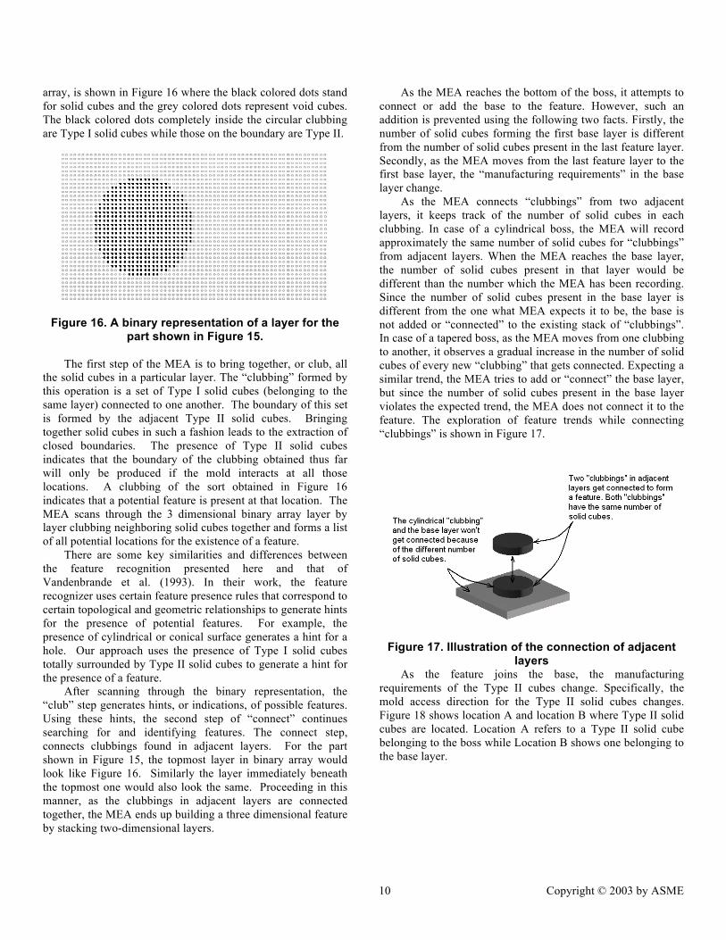
array, is shown in Figure 16 where the black colored dots stand for solid cubes and the grey colored dots represent void cubes. The black colored dots completely inside the circular clubbing are Type I solid cubes while those on the boundary are Type II.
Figure 16. A binary representation of a layer for the part shown in Figure 15.
The first step of the MEA is to bring together, or club, all
the solid cubes in a particular layer. The “clubbing” formed by this operation is a set of Type I solid cubes (belonging to the same layer) connected to one another. The boundary of this set is formed by the adjacent Type II solid cubes. Bringing together solid cubes in such a fashion leads to the extraction of closed boundaries. The presence of Type II solid cubes indicates that the boundary of the clubbing obtained thus far will only be produced if the mold interacts at all those locations. A clubbing of the sort obtained in Figure 16 indicates that a potential feature is present at that location. The MEA scans through the 3 dimensional binary array layer by layer clubbing neighboring solid cubes together and forms a list of all potential locations for the existence of a feature.
There are some key similarities and differences between the feature recognition presented here and that of Vandenbrande et al. (1993). In their work, the feature recognizer uses certain feature presence rules that correspond to certain topological and geometric relationships to generate hints for the presence of potential features. For example, the presence of cylindrical or conical surface generates a hint for a hole. Our approach uses the presence of Type I solid cubes totally surrounded by Type II solid cubes to generate a hint for the presence of a feature.
After scanning through the binary representation, the “club” step generates hints, or indications, of possible features. Using these hints, the second step of “connect” continues searching for and identifying features. The connect step, connects clubbings found in adjacent layers. For the part shown in Figure 15, the topmost layer in binary array would look like Figure 16. Similarly the layer immediately beneath the topmost one would also look the same. Proceeding in this manner, as the clubbings in adjacent layers are connected together, the MEA ends up building a three dimensional feature by stacking two-dimensional layers.
As the MEA reaches the bottom of the boss, it attempts to connect or add the base to the feature. However, such an addition is prevented using the following two facts. Firstly, the number of solid cubes forming the first base layer is different from the number of solid cubes present in the last feature layer. Secondly, as the MEA moves from the last feature layer to the first base layer, the “manufacturing requirements” in the base layer change.
As the MEA connects “clubbings” from two adjacent layers, it keeps track of the number of solid cubes in each clubbing. In case of a cylindrical boss, the MEA will record approximately the same number of solid cubes for “clubbings” from adjacent layers. When the MEA reaches the base layer, the number of solid cubes present in that layer would be different than the number which the MEA has been recording. Since the number of solid cubes present in the base layer is different from the one what MEA expects it to be, the base is not added or “connected” to the existing stack of “clubbings”. In case of a tapered boss, as the MEA moves from one clubbing to another, it observes a gradual increase in the number of solid cubes of every new “clubbing” that gets connected. Expecting a similar trend, the MEA tries to add or “connect” the base layer, but since the number of solid cubes present in the base layer violates the expected trend, the MEA does not connect it to the feature. The exploration of feature trends while connecting “clubbings” is shown in Figure 17.
Figure 17. Illustration of the connection of adjacent layers
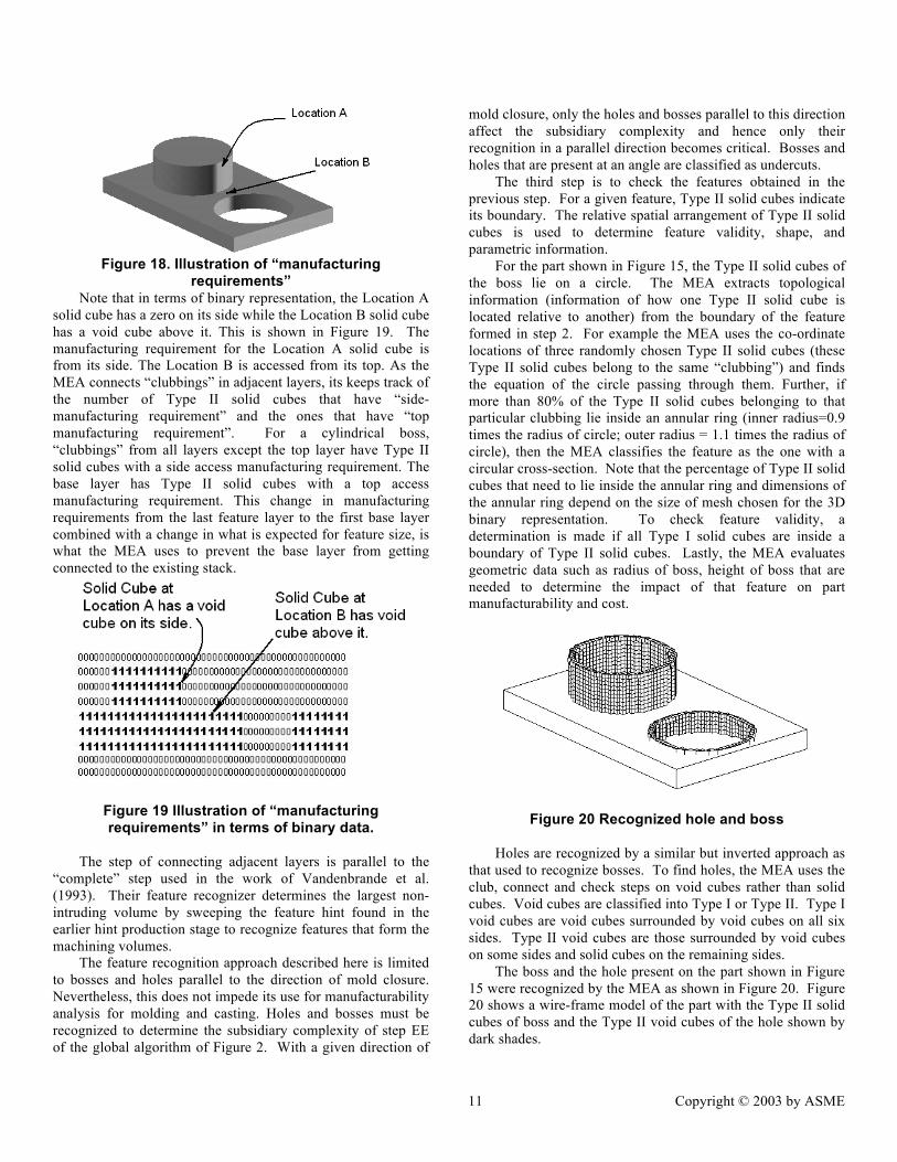
As the feature joins the base, the manufacturing requirements of the Type II cubes change. Specifically, the mold access direction for the Type II solid cubes changes. Figure 18 shows location A and location B where Type II solid cubes are located. Location A refers to a Type II solid cube belonging to the boss while Location B shows one belonging to the base layer.
11 Copyright © 2003 by ASME
Figure 18. Illustration of “manufacturing
requirements” Note that in terms of binary representation, the Location A
solid cube has a zero on its side while the Location B solid cube has a void cube above it. This is shown in Figure 19. The manufacturing requirement for the Location A solid cube is from its side. The Location B is accessed from its top. As the MEA connects “clubbings” in adjacent layers, its keeps track of the number of Type II solid cubes that have “side-manufacturing requirement” and the ones that have “top manufacturing requirement”. For a cylindrical boss, “clubbings” from all layers except the top layer have Type II solid cubes with a side access manufacturing requirement. The base layer has Type II solid cubes with a top access manufacturing requirement. This change in manufacturing requirements from the last feature layer to the first base layer combined with a change in what is expected for feature size, is what the MEA uses to prevent the base layer from getting connected to the existing stack.
Figure 19 Illustration of “manufacturing requirements” in terms of binary data.
The step of connecting adjacent layers is parallel to the
“complete” step used in the work of Vandenbrande et al. (1993). Their feature recognizer determines the largest non-intruding volume by sweeping the feature hint found in the earlier hint production stage to recognize features that form the machining volumes.
The feature recognition approach described here is limited to bosses and holes parallel to the direction of mold closure. Nevertheless, this does not impede its use for manufacturability analysis for molding and casting. Holes and bosses must be recognized to determine the subsidiary complexity of step EE of the global algorithm of Figure 2. With a given direction of
mold closure, only the holes and bosses parallel to this direction affect the subsidiary complexity and hence only their recognition in a parallel direction becomes critical. Bosses and holes that are present at an angle are classified as undercuts.
The third step is to check the features obtained in the previous step. For a given feature, Type II solid cubes indicate its boundary. The relative spatial arrangement of Type II solid cubes is used to determine feature validity, shape, and parametric information.
For the part shown in Figure 15, the Type II solid cubes of the boss lie on a circle. The MEA extracts topological information (information of how one Type II solid cube is located relative to another) from the boundary of the feature formed in step 2. For example the MEA uses the co-ordinate locations of three randomly chosen Type II solid cubes (these Type II solid cubes belong to the same “clubbing”) and finds the equation of the circle passing through them. Further, if more than 80% of the Type II solid cubes belonging to that particular clubbing lie inside an annular ring (inner radius=0.9 times the radius of circle; outer radius = 1.1 times the radius of circle), then the MEA classifies the feature as the one with a circular cross-section. Note that the percentage of Type II solid cubes that need to lie inside the annular ring and dimensions of the annular ring depend on the size of mesh chosen for the 3D binary representation. To check feature validity, a determination is made if all Type I solid cubes are inside a boundary of Type II solid cubes. Lastly, the MEA evaluates geometric data such as radius of boss, height of boss that are needed to determine the impact of that feature on part manufacturability and cost.
Figure 20 Recognized hole and boss
Holes are recognized by a similar but inverted approach as that used to recognize bosses. To find holes, the MEA uses the club, connect and check steps on void cubes rather than solid cubes. Void cubes are classified into Type I or Type II. Type I void cubes are void cubes surrounded by void cubes on all six sides. Type II void cubes are those surrounded by void cubes on some sides and solid cubes on the remaining sides.
The boss and the hole present on the part shown in Figure 15 were recognized by the MEA as shown in Figure 20. Figure 20 shows a wire-frame model of the part with the Type II solid cubes of boss and the Type II void cubes of the hole shown by dark shades.

12 Copyright © 2003 by ASME
Figure 21. A simple part with a hole.
The approach developed here for hole and boss recognition has some similarity with the alternating sum of volumes approach (Woo, 1982). The differences are briefly compared here. The comparison between our approach and the alternating sum of volumes approach is done with help of the part shown in Figure 21.
The alternating sum of volumes approach consists of computing the convex hull of the part and then subtracting the part from its convex hull to obtain the feature present. Carrying out such an operation on the part shown in Figure 21 gives the part shown in Figure 22 which is nothing but the hole recognized from the part.
Figure 22 Recognized hole
Our approach represents the part shown in Figure 21 by a 3-dimensional binary array. The uppermost layer of this binary array is the same as that shown in Figure 16. Here, the black colored dots stand for void cubes and the grey colored dots for solid cubes. The MEA clubs the void cubes to form five such layers and then connects them to form a feature that would be recognized as a cylindrical hole. This process is depicted in Figure 23.
Figure 23. A Graphical comparison between MEA and ASV approach
If the alternating sum of volumes (ASV) approach were
applied to one layer at a time for each of the five layers, it would produce a recognized hole as output. What the ASV approach achieves by subtraction of the part from its convex hull is achieved by the MEA by first representing the part in a binary form and then clubbing together adjacent zeros. In this context, the MEA could be viewed as a layer-by-layer application of the alternating sum of volumes approach. The use of binary representation for extracting features in MEA has specific advantages when applied to molding or casting operations because the binary representation allows simple procedures to determine the parting surface and the overall manufacturability of a part based on access to Type II solid cubes.
An important issue that needs to be addressed at this point is the size of the cube or binary mesh that was used to digitize the solid model. The finer the digitizing mesh, the better the results of the MEA. In order to recognize a boss with a radius of 10 mm, the digitizing mesh should at least be 1mm x 1mm x 1mm. As the mesh size becomes larger, the probability of missing a feature increases. The mesh size needed by the MEA depends on the size of manufacturing capabilities and the size of the smallest feature that needs to be recognized. For example due to manufacturing constraints, it may not be possible to die-cast a part with wall thickness less than 12.5 mm. Using this information, the mesh size of the MEA can be set to ensure recognition of valid features.
Summary Example A brief discussion on how the MEA performs automated
manufacturability analysis of injection-molded and die-cast parts is given next. This discussion is done for the simple part shown in Figure 15.
This part has a circular boss, a circular hole, and no undercuts. To determine manufacturability of this part, the following part features and characteristics need to be recognized. First, the circular hole and boss add to the die-cavity detail and hence increase the tooling cost of the part. Furthermore the parting surface of the part is non-planar and the part does not lie in one half of the mold. Lastly, the number of external and internal undercuts on the part is zero.
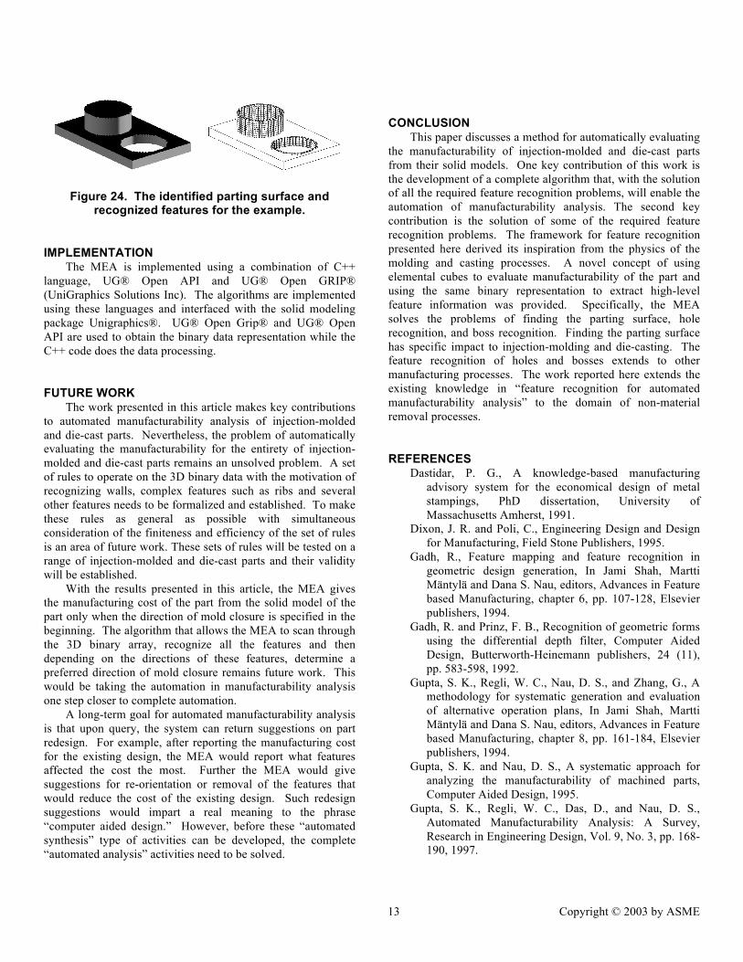
The left portion of Figure 24 shows the mold parting surface of the part as recognized by the MEA. The right portion of Figure 24 shows the hole and boss being recognized by the MEA. Thus given the solid model and direction of mold closure, the MEA recognizes the relevant features of the part in Figure 15. With this information, the questions in the global algorithm in Figure 2 can be answered and the cost of the part can be determined.
13 Copyright © 2003 by ASME
Figure 24. The identified parting surface and recognized features for the example.
IMPLEMENTATION The MEA is implemented using a combination of C++
language, UG® Open API and UG® Open GRIP® (UniGraphics Solutions Inc). The algorithms are implemented using these languages and interfaced with the solid modeling package Unigraphics®. UG® Open Grip® and UG® Open API are used to obtain the binary data representation while the C++ code does the data processing.
FUTURE WORK The work presented in this article makes key contributions
to automated manufacturability analysis of injection-molded and die-cast parts. Nevertheless, the problem of automatically evaluating the manufacturability for the entirety of injection-molded and die-cast parts remains an unsolved problem. A set of rules to operate on the 3D binary data with the motivation of recognizing walls, complex features such as ribs and several other features needs to be formalized and established. To make these rules as general as possible with simultaneous consideration of the finiteness and efficiency of the set of rules is an area of future work. These sets of rules will be tested on a range of injection-molded and die-cast parts and their validity will be established.
With the results presented in this article, the MEA gives the manufacturing cost of the part from the solid model of the part only when the direction of mold closure is specified in the beginning. The algorithm that allows the MEA to scan through the 3D binary array, recognize all the features and then depending on the directions of these features, determine a preferred direction of mold closure remains future work. This would be taking the automation in manufacturability analysis one step closer to complete automation.
A long-term goal for automated manufacturability analysis is that upon query, the system can return suggestions on part redesign. For example, after reporting the manufacturing cost for the existing design, the MEA would report what features affected the cost the most. Further the MEA would give suggestions for re-orientation or removal of the features that would reduce the cost of the existing design. Such redesign suggestions would impart a real meaning to the phrase “computer aided design.” However, before these “automated synthesis” type of activities can be developed, the complete “automated analysis” activities need to be solved.
CONCLUSION This paper discusses a method for automatically evaluating
the manufacturability of injection-molded and die-cast parts from their solid models. One key contribution of this work is the development of a complete algorithm that, with the solution of all the required feature recognition problems, will enable the automation of manufacturability analysis. The second key contribution is the solution of some of the required feature recognition problems. The framework for feature recognition presented here derived its inspiration from the physics of the molding and casting processes. A novel concept of using elemental cubes to evaluate manufacturability of the part and using the same binary representation to extract high-level feature information was provided. Specifically, the MEA solves the problems of finding the parting surface, hole recognition, and boss recognition. Finding the parting surface has specific impact to injection-molding and die-casting. The feature recognition of holes and bosses extends to other manufacturing processes. The work reported here extends the existing knowledge in “feature recognition for automated manufacturability analysis” to the domain of non-material removal processes.
REFERENCES Dastidar, P. G., A knowledge-based manufacturing
advisory system for the economical design of metal stampings, PhD dissertation, University of Massachusetts Amherst, 1991.
Dixon, J. R. and Poli, C., Engineering Design and Design for Manufacturing, Field Stone Publishers, 1995.
Gadh, R., Feature mapping and feature recognition in geometric design generation, In Jami Shah, Martti Mäntylä and Dana S. Nau, editors, Advances in Feature based Manufacturing, chapter 6, pp. 107-128, Elsevier publishers, 1994.
Gadh, R. and Prinz, F. B., Recognition of geometric forms using the differential depth filter, Computer Aided Design, Butterworth-Heinemann publishers, 24 (11), pp. 583-598, 1992.
Gupta, S. K., Regli, W. C., Nau, D. S., and Zhang, G., A methodology for systematic generation and evaluation of alternative operation plans, In Jami Shah, Martti Mäntylä and Dana S. Nau, editors, Advances in Feature based Manufacturing, chapter 8, pp. 161-184, Elsevier publishers, 1994.
Gupta, S. K. and Nau, D. S., A systematic approach for analyzing the manufacturability of machined parts, Computer Aided Design, 1995.
Gupta, S. K., Regli, W. C., Das, D., and Nau, D. S., Automated Manufacturability Analysis: A Survey, Research in Engineering Design, Vol. 9, No. 3, pp. 168-190, 1997.

14 Copyright © 2003 by ASME
Henderson, M. R., Extraction of feature information from three-dimensional CAD data, PhD dissertation, Purdue University, 1984.
Henderson, M. R., Srinath, G., Stage, R., Walker, K. and Regli, W., Boundary Representation-based Feature Identification, In Jami Shah, Martti Mäntylä and Dana S. Nau, editors, Advances in Feature based Manufacturing, chapter 2, pp. 15-38, Elsevier publishers, 1994.
Joshi, S. and Chang, T. C., Graph based heuristics for recognition of machined features from a 3D solid model, Computer Aided Design, 20 (2), pp. 58-66, 1988.
J. W. Van Vliet C. A. Van Luttervelt and H. J. J. Kals, State Of the Art report on Design for Manufacturing. In Design Engineering Technical Conference, ASME, 1999. INCLUDE PAPER NUMBER
Kramer, T. R., Nau, D. S., Gupta, S. K., Regli, W. and Zhang, G., Development of Machining Alternatives, Based on MRSEVs, Proc. of the ASME Computers in Engineering Conference, 1993.
Kyprianou, L., Shape classification in Computer Aided Design, PhD dissertation, Cambridge, UK, 1980.
Lei, S. and Qamhiyah, A., Wavelet-based surface analysis for form feature extraction, Proc. of Design for Manufacturing Conf. ASME, 2000. INCLUDE PAPER NUMBER
Mill, F.G., Naish, J.C. and Salmon, J.C., Design for machining with a simultaneous-engineering workstation, Computer Aided Design, pp. 521-527, 1994.
Mortenson, M., Geometric modeling, Wiley, 1985. Poli, C., Escudero, J. and Fernandez, R., How Part Design
Affects Injection Molding Tool Costs, Machine Design, 1988.
Poli, C., Fredette, L. and Sunderland, J. E., Trimming the cost of die-castings, Machine Design, 1990.
Poli, C., Design for Manufacturing: A Structured Approach, Butterworth Heinemann, Boston, 2001.
Prabhakar, S., An experiment on the use of neural nets in form feature recognition, Master’s thesis, Arizona State University, 1990.
Priest, J. W. and Sanchez, J. M., An empirical methodology for measuring producibility early in product development., International Journal of Computer Integrated Manufacturing, 4(2),pp. 114--120, 1991.
Regli, W. and Nau, D. S., Building a general approach to feature recognition of material removal shape element volumes (MRSEVs), Second Symposium on Solid Modeling Foundations and CAD/CAM Applications, 1993.
Regli, W., Gupta, S. K. and Nau, D. S., Feature recognition for manufacturability analysis, ASME Computers in Engineering Conference, pp. 93-104,1994.
Regli, W., Geometric Algorithms for the Recognition of Features from Solid Models, Ph.D. dissertation, University of Maryland, 1995.
Requicha, A. A. G. and Han, J., Feature recognition from CAD models, IEEE Computer Graphics, 1998.
Sakurai, H. and Gossard, D. C., Shape Feature Recognition from 3D solid models, ASME Computers in Engineering, 1988.
Shah, J., Mäntylä, M. and Nau, D. S., editors, Advances in Feature based Manufacturing, chapter 1, pp. 1-11, Elsevier publishers, 1994.
Shah, J. and Mäntylä, M., Parametric and Feature-Based CAD/CAM: Concepts, techniques and applications, Wiley–Interscience Publication, 1995.
Trucks, H. E., Designing for Economical Production, Society of Manufacturing Engineers, MI, 1987.
UniGraphics Solutions Inc., V18.0 UniGraphics Help, 2001.
Vandenbrande, J., Automatic recognition of machinable features in solid models, PhD dissertation, University of Southern California, 1990.
Vandenbrande, J. H. and Requicha, A. A. G., Spatial reasoning for the automatic recognition of machinable features in solid models, IEEE Pattern Analysis and Machine Intelligence, vol. 15, no. 12, pp. 1269-1285, 1993.
Woo, T., Feature recognition by volume decomposition, Proc. of Conference CAD/CAM technology in Mechanical Engineering, Cambridge, MA, 1982.
Yong Se Kim, Volumetric feature recognition using convex decomposition, In Jami Shah, Martti Mäntylä and Dana S. Nau, editors, Advances in Feature based Manufacturing, chapter 3, pp. 39-63, Elsevier publishers, 1994.
Zeid, I., CAD/CAM Theory and Practice, McGraw-Hill, 1991.

15 Copyright © 2003 by ASME
APPENDIX Start
Whether part is flat
or Box shaped? AA
16 Copyright © 2003 by ASME
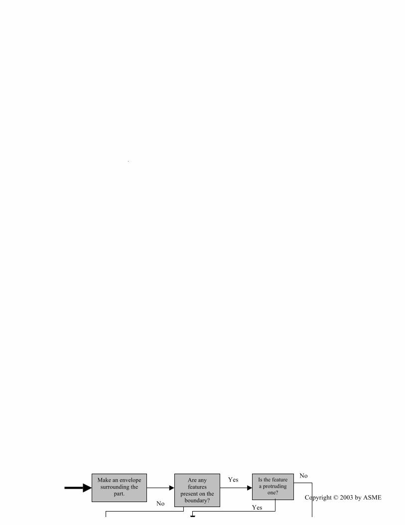
Make an envelope surrounding the
part.
Are any features
present on the boundary?
Is the feature a protruding
one?
Mark the feature as a potential
Yes
Yes
No
No

17 Copyright © 2003 by ASME
Enclose the part in its Basic Envelope
Recognize features
Is it an insert?
Direction of mold closure is in the
direction of insert Yes

18 Copyright © 2003 by ASME
Recognize features
Set count = number of recognized
features

19 Copyright © 2003 by ASME
List of undercuts
Set Count = Number of undercuts
Is the undercut ext. or internal?
Is Count > 0?
20 Copyright © 2003 by ASME
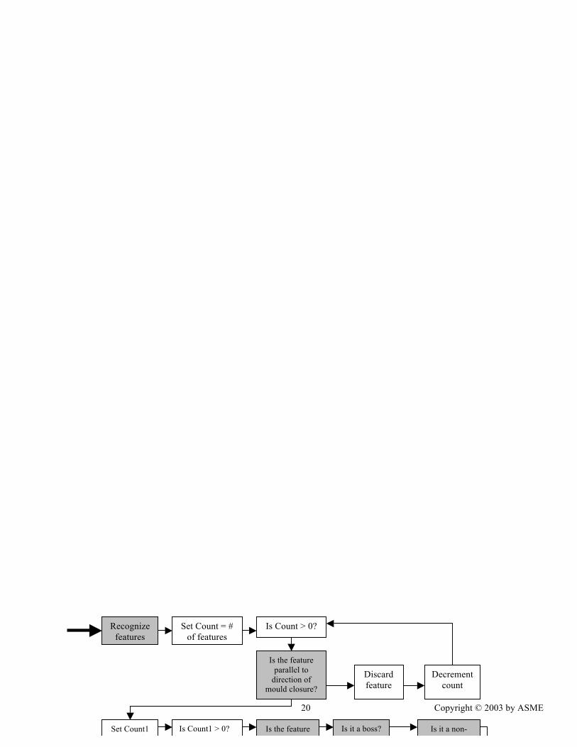
Set Count1 = No of features.
Is Count1 > 0? Is the feature a hole?
Recognize features
Set Count = # of features
Is Count > 0?
Is the feature parallel to
direction of mould closure?
Discard feature
Decrement count
Is it a boss? Is it a non-peripheral rib and/or wall?

![การหา potassium ในสารตัวอย่าง โดยใช้เทคนิค flow injection ... · [1] เทคนิค Flow injection analysis หรือ](https://img.pdfslide.us/doc/110x75/5b48a14c7f8b9a3a058cf6f9/-potassium-.jpg)


![Flow Injection Analysis (FIA) Sequential Injection Analysis …€¦ · · 2013-11-06Flow Injection Analysis (FIA) Sequential Injection Analysis (SIA) ... [mM] • Sensitive (ppt/nM)](https://img.pdfslide.us/doc/110x75/5ad649697f8b9a1a028e3577/flow-injection-analysis-fia-sequential-injection-analysis-2013-11-06flow.jpg)