Embed Size (px)
Citation preview

1
®
WA-72B (2 ton) WA-73B (4 ton) WA-75B (10 ton)
WA-85 (20 ton)
Weaver Jack
Seal Kit Ins tructions
WA-72B 2 Ton Model WA-75B 10 Ton Model
WA-73B 4 Ton Model WA-85 20 Ton Model
• Seal Kit Identification
• Seal Kit Components
• In stallion Instructions

2
How Can I Identify My Jack?
Using the following Dimension Chart, -
Compare Features and Measurements
MODEL CAP.
(tons)
FRONT
WHEELS
SADDLE STYLE
AND SIZE
FRAME
LENGTH
JACK
WEIGHT
WA-72B 2 Two - 4"
Diameter
Triangular or
Round
5"' to 6"
51" 136 lbs
WA-73B 4 Two - 5"
Diameter
Triangular or
Round
5" to 6"
58" 212 lbs
WA-75B 10 Two - 7"
Diameter
Round
9"
66" 356 lbs
WA-85 20 Three- 7"
Diameter
Square
7"
69" 531 lbs
Typical Seal Kit Components for Weaver
2, 4, 10 & 20 Ton Service Jacks

3
How Can I Identify The
Jack Model Number?
Using the following Description Chart, -
Determine Whether You Have an A or B Model
MODEL CAP.
TONS CYLINDER DESCRIPTION KIT #
WA-72A 2 Head of cylinder is held down
by TWO Cotter Keys KJ-106
WA-72B 2 Head of cylinder is held down
by Metal Tabs KJ-106
WA-73A 4 Head of cylinder is held down
by TWO Cotter Keys KJ-107
WA-73B 4 Head of cylinder is held down
by Metal Tabs KJ-107
WA-75A 10 Head of cylinder is held down
by A Large Pin Through The Frame KJ-108
WA-75B 10 Head of cylinder is held down
by TWO Bolts Inside Frame KJ-108
WA-85 20 Head of cylinder is held down
by TWO Bolts Inside Frame KJ-109

4
INSTALLATION INSTRUCTIONS FOR WEAVER SEAL KITS
These Jack Cylinder Service Kits are for minor cylinder repairs only, if additional servicing is required have
repairs performed by a qualified hydraulic jack repair center.
Use Safety Solvent or Mineral Spirits to clean parts—blow dry with compressed air.
Do not use Gasoline, lacquer thinner or any other solvents as these will damage the seals.
Use AW-32 Light Hydraulic Oil (or oil that meets MIL•F•17111 011 specifications)

5
To Remove The Cylinder:
1. Remove the cotter pin (pins) or bolts in the cross head.
2. Remove the cotter and pin in the pump.
3. Remove the cotter and pin in the release yoke.
4. Place cotter key in while depressing foot pedal.
This allows for easy removal and reassembly if spring is left on return rod.
5. Raise the lifting arm by means of the saddle bracket, and place a block of wood between the arm and frame
to hold up the arm.
6. This releases the cylinder at the forward end, so that it may be removed as a complete unit, for service.
Piston and Pump Assembly Derail for Weaver Jack Cylinders
6
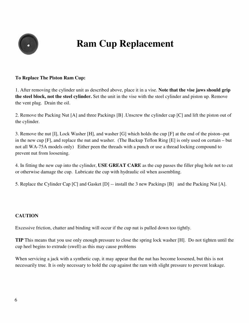
Ram Cup Replacement
To Replace The Piston Ram Cup:
1. After removing the cylinder unit as described above, place it in a vise. Note that the vise jaws should grip
the steel block, not the steel cylinder. Set the unit in the vise with the steel cylinder and piston up. Remove
the vent plug. Drain the oil.
2. Remove the Packing Nut [A] and three Packings [B] .Unscrew the cylinder cap [C] and lift the piston out of
the cylinder.
3. Remove the nut [I], Lock Washer [H], and washer [G] which holds the cup [F] at the end of the piston--put
in the new cup [F], and replace the nut and washer. (The Backup Teflon Ring [E] is only used on certain – but
not all WA-75A models only) Either peen the threads with a punch or use a thread locking compound to
prevent nut from loosening.
4. In fitting the new cup into the cylinder, USE GREAT CARE as the cup passes the filler plug hole not to cut
or otherwise damage the cup. Lubricate the cup with hydraulic oil when assembling.
5. Replace the Cylinder Cap [C] and Gasket [D] -- install the 3 new Packings [B] and the Packing Nut [A].
CAUTION
Excessive friction, chatter and binding will occur if the cup nut is pulled down too tightly.
TIP This means that you use only enough pressure to close the spring lock washer [H]. Do not tighten until the
cup heel begins to extrude (swell) as this may cause problems
When servicing a jack with a synthetic cup, it may appear that the nut has become loosened, but this is not
necessarily true. It is only necessary to hold the cup against the ram with slight pressure to prevent leakage.

7
Pump Cup Replacement
To Replace The Pump Cup (small cup):
1. Turn the cylinder unit pump end upward in the vise.
2. Unscrew the packing nut [M] - Remove three Packings [L] and pull out the pump plunger. Remove the Nut
[J] that holds Cup [K] to the end of plunger; insert new cup, new packings and replace the nut and washers.
3. Lubricate the cup with hydraulic oil when reassembling. Either peen the threads with a punch or use a thread
locking compound to prevent the nut from loosening.
Release Valve Group and Ball Valve Assembly Derail

8
Ball Valve Replacement
Ball Valve Replacement:
1. Remove the Ball Chamber Plug [V]. Remove the Two Balls [X&Z] and the Ball weight [Y].
2. Reassemble with the two new Balls [X&Z], New Plug Gasket [W] and Ball Weight [Y] (reuse the existing
Ball weight). Ball Weight is installed between the two balls.
IMPORTANT: Whenever it is necessary to loosen or remove the Ball Chamber Plug, the Gasket [W] should
be replaced with a new one. Oil leakage at this point is usually caused by trying to reuse an old gasket over
again.
Release Valve Packing Housing "O"-Ring Replacement
Release Group Needle Valve Packing “O” Rings Replacement:
1. Measure accurately the distance from the Bracket [O] to the first Nut [P] on the compression spring. Write
this measurement down. (This is approximately 2 inches)
2. Loosen the Packing Nut [R]. Remove Nuts [P] & [Q], the Spring, the Valve Rod [N] , the Valve Guide
[OO] and the Packing Nut [R]. It is not necessary to remove the rod clevis.
3. Remove the Packing Housing [S] and replace the two “O” rings [T&U]. Now reinsert the Packing Housing
[S]. Reassemble the Needle Valve and parts with the Packing Nut [R] tightly secured.
4. Tighten the adjusting nut [P] to the original dimension that you wrote down and lock this nut with Nut [Q].

9
Release Valve Group (upper ) - Pump Assembly (lower)
Release Group - Needle Valve Adjustment
Release Group Needle Valve Adjustment:
In the release group assembly, the spring governs the load that the Jack will lift. When the pressure within the
cylinder overcomes the spring tension then the release valve floats off the seat. It is Imperative that the release
valve floats freely in the release group assembly. To check- use your forefinger and thumb to grasp the release
valve where the release clevis pin passes thru, and wiggle from side to side. There should be a minimum of
.002 to.004 clearance in the Release Vale Guide [OO]. If no movement is noted, follow these steps:
Refer to above Diagram
Measure accurately the distance from the Bracket [O] to the first Nut [P] on the compression spring. Write this
measurement down. (This is approximately 2 inches)
Remove Nuts [P] & [Q], the Spring, the Valve Rod [N] and the Valve Guide [OO]. It is not necessary to
loosen the Packing Nut.
Next, insert the Valve Rod [N] thru the Bracket’s [O] opening, slide the Release Valve Guide [OO] onto the
rod, but not seated in the hole, and insert the rod [N] into the Packing Nut’s [R] opening.
Gently Tap the end of the release rod [N] with a hammer until it stays firmly seated in the internal needle seat.

10
Slide the Release Valve Guide [OO] towards the Bracket [O] (normally it will smoothly fit into the bracket
hole) and then noting where the center alignment of the rod in the bracket hole is off -- Tap the welded bracket
accordingly with a hammer to gently bend the bracket and correct the misalignment. It is in alignment when
you can smoothly slide the Valve Guide into the Bracket’s hole.
Reassemble the Release Valve and parts. Tighten the adjusting nut [P] to the original dimension that you
wrote down and lock this nut with Nut [Q] and then test the Jack for proper operation.
Troubleshooting
SYMPTOMS CORRECTIVE ACTION
1. Jack will not raise saddle. 1. Check the oil level.
2. Perform the Ball Valve Test
2. Oil spurts out the vent hole. 1. The jack is overfilled with oil.
3. Jack will only lift part way up. 1. It may be low on oil. Check and refill.
4. Jack will not lift a load. 1. Check for proper oil level.
2. If pumping falls to raise the rated load, the
lower ball valve may be leaking, and it should
be inspected for dirt or other obstructions.
5. If the load rises on the down
stroke of the handle and then
immediately settles back down
while forcing the jack handle up.
This means that the upper ball valve may be
leaking, and it should be inspected for dirt or
other obstructions.
6. Jack bleeds down while under
load.
1. The Release Handle may not be closed
2. The Release Valve may be leaking. Replace
the release valve packing housing “O” Rings.
3. The Release Needle Valve may need to be
adjusted.
7. Jack only rises on half-stroke,
and then settles back down while
forcing the handle up.
This means that the jack may be Air Bound.
11
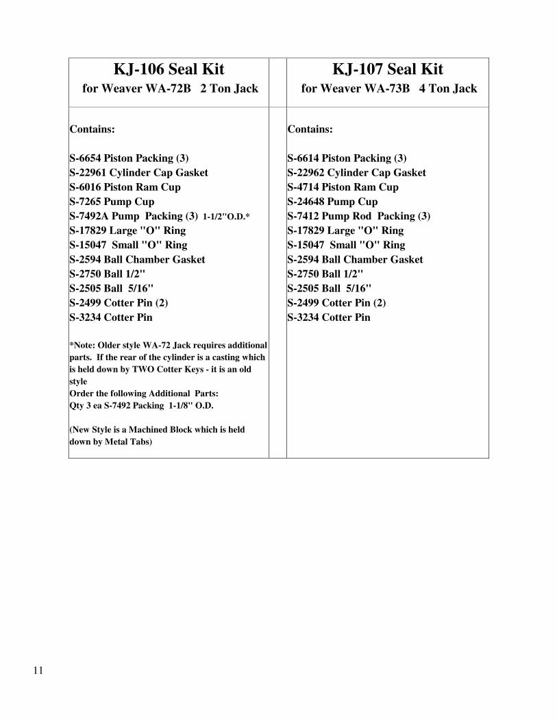
KJ-106 Seal Kit
for Weaver WA-72B 2 Ton Jack
KJ-107 Seal Kit
for Weaver WA-73B 4 Ton Jack
Contains:
S-6654 Piston Packing (3)
S-22961 Cylinder Cap Gasket
S-6016 Piston Ram Cup
S-7265 Pump Cup
S-7492A Pump Packing (3) 1-1/2"O.D.*
S-17829 Large "O" Ring
S-15047 Small "O" Ring
S-2594 Ball Chamber Gasket
S-2750 Ball 1/2"
S-2505 Ball 5/16"
S-2499 Cotter Pin (2)
S-3234 Cotter Pin
*Note: Older style WA-72 Jack requires additional
parts. If the rear of the cylinder is a casting which
is held down by TWO Cotter Keys - it is an old
style
Order the following Additional Parts:
Qty 3 ea S-7492 Packing 1-1/8" O.D.
(New Style is a Machined Block which is held
down by Metal Tabs)
Contains:
S-6614 Piston Packing (3)
S-22962 Cylinder Cap Gasket
S-4714 Piston Ram Cup
S-24648 Pump Cup
S-7412 Pump Rod Packing (3)
S-17829 Large "O" Ring
S-15047 Small "O" Ring
S-2594 Ball Chamber Gasket
S-2750 Ball 1/2"
S-2505 Ball 5/16"
S-2499 Cotter Pin (2)
S-3234 Cotter Pin

12
KJ-108 Seal Kit
for Weaver WA-75B 10 Ton Jack
KJ-109 Seal Kit
for Weaver WA-85 20 Ton Jack
Contains:
S-6615 Piston Rod Packing (3)
S-22963 Cylinder Cap Gasket
S-24649 Piston Ram Cup
S-24648 Pump Cup
S-7412 Pump Rod Packing (3)
S-17829 Large "O" Ring
S-15047 Small "O" Ring
S-5125 Ball Chamber Gasket
S-5122 Ball 5/8"
S-3282 Ball 3/8"
S-3083 Cotter Pin
S-24703 Teflon Ring
Contains:
S-16022 Piston Rod Packing (3)
S-22964 Cylinder Cap Gasket
S-16023 Piston Ram Cup
S-24648 Pump Cup
S-7412 Pump Rod Packing (3)
S-17829 Large "O" Ring
S-15047 Small "O" Ring
S-5125 Ball Chamber Gasket
S-5122 Ball 5/8"
S-3282 Ball 3/8"
S-3083 Cotter Pin