Embed Size (px)
Citation preview
Weathering Steel for Highway Structures
DN-STR-03002 December 2002
Design Standards DN
TRANSPORT INFRASTRUCTURE IRELAND (TII) PUBLICATIONS
About TII Transport Infrastructure Ireland (TII) is responsible for managing and improving the country’s national road and light rail networks. About TII Publications TII maintains an online suite of technical publications, which is managed through the TII Publications website. The contents of TII Publications is clearly split into ‘Standards’ and ‘Technical’ documentation. All documentation for implementation on TII schemes is collectively referred to as TII Publications (Standards), and all other documentation within the system is collectively referred to as TII Publications (Technical). This system replaces the NRA Design Manual for Roads and Bridges (NRA DMRB) and the NRA Manual of Contract Documents for Road Works (NRA MCDRW). Document Attributes Each document within TII Publications has a range of attributes associated with it, which allows for efficient access and retrieval of the document from the website. These attributes are also contained on the inside cover of each current document, for reference. For migration of documents from the NRA and RPA to the new system, each current document was assigned with new outer front and rear covers. Apart from the covers, and inside cover pages, the documents contain the same information as previously within the NRA or RPA systems, including historical references such as those contained within NRA DMRB and NRA MCDRW. Document Attributes
TII Publication Title Weathering Steel for Highway Structures TII Publication Number
DN-STR-03002
Activity Design (DN) Document Set Standards
Stream Structures (STR) Publication Date December 2002
Document Number
03002 Historical Reference
BD 7
NRA DMRB and MCDRW References For all documents that existed within the NRA DMRB or the NRA MCDRW prior to the launch of TII Publications, the NRA document reference used previously is listed above under ‘historical reference’. The TII Publication Number also shown above now supersedes this historical reference. All historical references within this document are deemed to be replaced by the TII Publication Number. For the equivalent TII Publication Number for all other historical references contained within this document, please refer to the TII Publications website.
National Roads Authority Volume 2 Section 3 Design Manual for Roads and Bridges Part 8 BD 7/01 Addendum
December 2002 1
NRA ADDENDUM TO
BD 7/01
WEATHERING STEEL FOR HIGHWAY STRUCTURES
December 2002
This Addendum supersedes the NRA Addendum dated December 2000 to Standard BD 7/81. The revisions
have arisen due to the publication of Standard BD 7/01 dated November 2001, which supersedes BD 7/81.
Standard BD 7/01 - Weathering Steel for Highway Structures - is applicable in Ireland with the following
amendments:
GENERAL
1. The Standard provides specification requirements for use in public purchasing contracts. It does not
lay down legislation requirements for products and materials used in road construction in Ireland.
2. At several locations:
For: “Overseeing Organisation”
Read: “National Roads Authority”;
For: “BS EN”
Read: “IS EN”;
For: “highway”
Read: “road”.
National Roads Authority Volume 2 Section 3 Design Manual for Roads and Bridges Part 8 BD 7/01 Addendum
December 2002 2
SPECIFIC
1. Page 1/1, Paragraph 1.2(a):
Delete Paragraph 1.2(a) and replace with:
“(a) (Not used)”.
2. Page 1/1, Paragraph 1.4:
Delete Paragraph 1.4 and replace with:
“1.4 This Standard should be used forthwith
for all schemes for the construction and/or
improvement of national roads. The Standard
should be applied to the design of schemes
already being prepared unless, in the opinion of
the National Roads Authority, application
would result in significant additional expense or
delay progress. In such cases, Design
Organisations should confirm the application of
this Standard to particular schemes with the
National Roads Authority.”
3. Page 2/1, Paragraph 2.2(b), line 3:
For: “steel. Surfaces”
Read: “steel surfaces”.
4. Page 2/1, Paragraph 2.2:
Insert new Paragraph 2.2(h) at the end of Paragraph 2.2:
“(h) for bridges over roads subjected to de-
icing salt spray where the headroom for
the road below the structure is less than
7.5m.”
5. Page 2/1, Paragraph 2.3, line 4:
Delete the second and third sentences “For new works,…Volume 5, Section 2.” and replace with:
“For new works, the protective treatment shall
be in accordance with the NRA Specification
for Road Works, Series 1900.”
6. Page 4/1, Paragraph 4.6, line 1:
Delete: “, in accordance with BA 42 (which is mandatory in Scotland)”.
7. Page 5/1, Paragraph 5.1, line 8:
Delete the last sentence “Specification for…Clause 1803.” and replace with:
“Specifications for welding consumables are
defined in the NRA Specification for Road
Works, Series 1800.”
National Roads Authority Volume 2 Section 3 Design Manual for Roads and Bridges Part 8 BD 7/01 Addendum
December 2002 3
8. Page 6/1, Paragraph 6.1, line 2:
For: “General Inspections.”
Read: “Principal Inspections.”
9. Page 6/1, Paragraph 6.4, line 1:
For: “General Inspections in accordance with BD 63 (DMRB 3.1.4)”
Read: “Principal Inspections”.
10. Page 6/1, Paragraph 6.6, line 5:
For: “at each General Inspection or at intervals not exceeding 2 years.”
Read: “at each Principal Inspection.”
11. Page 6/1, Paragraph 6.9, line 7:
For: “Principal Inspections specified in BD 63 (DMRB 3.1.4) possibly at 6 year intervals.”
Read: “Principal Inspections.”
12. Page 6/2, Paragraph 6.14, line 4:
For: “Principal Inspection (DMRB 3.1.4 BD 63),”
Read: “Principal Inspection,”.
13. Page 7/1, Paragraph 7.3, line 3:
For: “the same maintenance paint systems recommended in the MCHW Volume 5, Section 2.”
Read: “an appropriate maintenance paint system.”
14. Page 8/1, Section 8.1, Title:
For “8.1 British Standards Institution”
Read: “8.1 Irish and British Standards”.
15. Page 8/1, Sections 8.3 and 8.4:
Delete Sections 8.3 and 8.4 and replace with:
“8.3 NRA Documents
NRA Manual of Contract Documents for Road
Works, Volume 1: Specification for Road
Works.
8.4 (Not used)”
National Roads Authority Volume 2 Section 3 Design Manual for Roads and Bridges Part 8 BD 7/01 Addendum
December 2002 4
16. Page 9/1, Chapter 9:
Delete text and replace with:
“9.1 All technical enquiries or comments on this Standard should be sent in writing to:
Head of Project Management and Engineering
National Roads Authority
St Martin’s House
Waterloo Road
Dublin 4”
…………………………………………
E O’CONNOR
Head of Project Management and
Engineering
November 2001
DESIGN MANUAL FOR ROADS AND BRIDGES
VOLUME 2 HIGHWAY STRUCTURES:DESIGN(SUBSTRUCTURES ANDSPECIAL STRUCTURES)
SECTION 3 MATERIALS ANDCOMPONENTS
PART 8
BD 7/01
WEATHERING STEEL FOR HIGHWAYSTRUCTURES
SUMMARY
This Standard replaces BD 7/81. The requirementsspecified here cover design, construction and in-servicemaintenance aspects. It shall be used in conjunctionwith relevant parts of BS 5400 as implemented byoverseeing organizations, except where otherwiseindicated.
INSTRUCTIONS FOR USE
This revised Standard is to be incorporated in theManual.
1. This document supersedes BD 7/81, which isnow withdrawn.
2. Remove existing contents page for Volume 2 andinsert new contents page dated for Volume 2November 2001.
3. Remove BD 7/81, which is superseded byBD 7/01 and archive as appropriate.
4. Insert BD 7/01 in Volume 2, Section 3, Part 8.
5. Archive this sheet as appropriate.
Note: A quarterly index with a full set of VolumeContents Pages is available separately from TheStationery Office Ltd.
BD 7/01
Weathering Steel forHighway Structures
Summary: This Standard replaces BD 7/81. The requirements specified here cover design,construction and in-service maintenance aspects. It shall be used in conjunctionwith relevant parts of BS 5400 as implemented by overseeing organizations,except where otherwise indicated.
DESIGN MANUAL FOR ROADS AND BRIDGES
THE HIGHWAYS AGENCY
SCOTTISH EXECUTIVE DEVELOPMENT DEPARTMENT
THE NATIONAL ASSEMBLY FOR WALESCYNULLIAD CENEDLAETHOL CYMRU
THE DEPARTMENT FOR REGIONAL DEVELOPMENTNORTHERN IRELAND
Volume 2 Section 3Part 8 BD 7/01
November 2001
REGISTRATION OF AMENDMENTS
Amend Page No Signature & Date of Amend Page No Signature & Date ofNo incorporation of No incorporation of
amendments amendments
Registration of Amendments
Volume 2 Section 3Part 8 BD 7/01
November 2001
REGISTRATION OF AMENDMENTS
Amend Page No Signature & Date of Amend Page No Signature & Date ofNo incorporation of No incorporation of
amendments amendments
Registration of Amendments
VOLUME 2 HIGHWAY STRUCTURES:DESIGN(SUBSTRUCTURES ANDSPECIAL STRUCTURES)
SECTION 3 MATERIALS ANDCOMPONENTS
PART 8
BD 7/01
WEATHERING STEEL FOR HIGHWAYSTRUCTURES
Contents
Chapter
1. Introduction
2. Limitations on Use
3. Design - Corrosion Allowances
4. Design - General Considerations
5. Construction
6. Inspection and Monitoring
7. Maintenance
8. References
9. Enquiries
Appendix A Environmental Classification withRespect to the Use of Weathering Steel
Appendix B Residual Steel Thickness MeasurementUsing Ultrasonic Gauges
DESIGN MANUAL FOR ROADS AND BRIDGES
November 2001
Volume 2 Section 3Part 8 BD 7/01
November 2001 1/1
Chapter 1Introduction
1. INTRODUCTION
Mandatory Sections
1.1 Sections of this document which form partof the standards of the Overseeing Organisationsare highlighted by being contained in boxes. Theseare the sections with which the DesignOrganisations shall comply, or shall have agreed asuitable departure from standard with the relevantOverseeing Organisation. The remainder of thedocument contains advice and enlargement whichis commended to Design Organisations for theirconsideration.
Major changes in this version of the Standard
1.2 The present version of the Standard incorporatesthe outcome of the research into the corrosivity of theenvironment under bridge decks and in-serviceperformance of weathering steel used in bridges. Alsoinformation gathered from the use of weathering steelsin highway construction in other countries. Majorchanges to BD 7/81 include:
(a) removal of the 7.5 metres headroom limitationfor bridges over roads subjected to de-icing saltsprays. Such bridges are now allowed to bedesigned at standard headroom requirements
(b) introduction of a minimum headroomrequirement of 2.5 metres for crossings overwater
(c) reduction in thickness allowances
(d) options for appropriate welding consumables
(e) additional information on inspections, monitoringand maintenance
(f) updated references including InternationalStandards (ISOs) for classification ofenvironments.
1.3 This Standard replaces BD 7/81. It shall beused in conjunction with relevant Parts ofBS 5400, as implemented by the OverseeingOrganisations, except where otherwise indicated.
Implementation
1.4 This Standard shall be used forthwith on allschemes for the construction and improvement oftrunk roads, including motorways currently beingprepared, provided that, in the opinion of theOverseeing Organisation, this would not result insignificant additional expense or delay. DesignOrganisations shall confirm its application toparticular schemes with the OverseeingOrganisation. In Northern Ireland this standardapplies to all roads so designated by theOverseeing Organisation.
Definitions
1.5 Weathering steel (or weather resistant steel)shall be taken to mean structural steels withimproved atmospheric corrosion resistance,supplied in accordance with BS EN 10155, and hotfinished structural hollow sections in weatherresistant steels, supplied in accordance withBS 7668.
Scope
1.6 This Standard specifies requirements for theuse of weathering steel for the construction ofhighway structures. The requirements coverdesign, construction and in-service maintenance.
1.7 Weathering Steels are a class of low alloy steelscontaining about 2% of specific alloying elements suchas copper, chromium, silicon and in some casesphosphorus.
1.8 Structural steels to BS EN 10155 are available ingrades S235 and S355; grade S235 is unlikely to beused in bridgework. Structural steels to BS 7668 areavailable in grade S345.
Volume 2 Section 3Part 8 BD 7/01
November 20011/2
Chapter 1Introduction
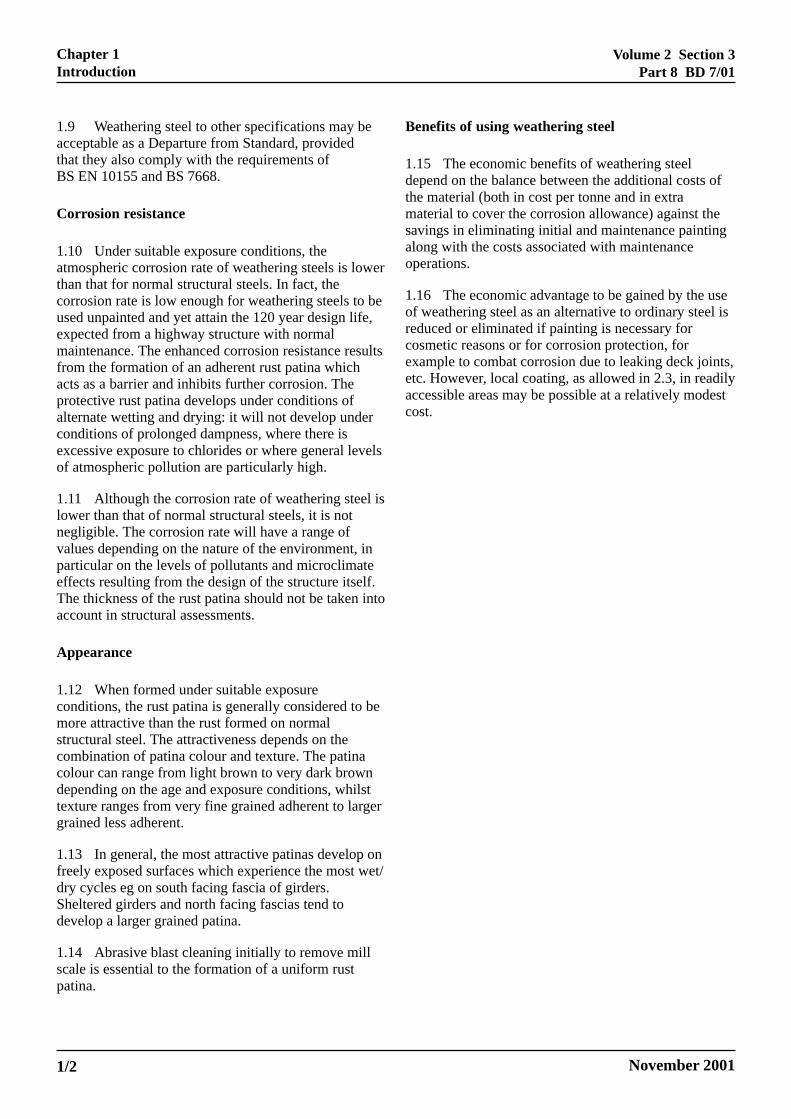
1.9 Weathering steel to other specifications may beacceptable as a Departure from Standard, providedthat they also comply with the requirements ofBS EN 10155 and BS 7668.
Corrosion resistance
1.10 Under suitable exposure conditions, theatmospheric corrosion rate of weathering steels is lowerthan that for normal structural steels. In fact, thecorrosion rate is low enough for weathering steels to beused unpainted and yet attain the 120 year design life,expected from a highway structure with normalmaintenance. The enhanced corrosion resistance resultsfrom the formation of an adherent rust patina whichacts as a barrier and inhibits further corrosion. Theprotective rust patina develops under conditions ofalternate wetting and drying: it will not develop underconditions of prolonged dampness, where there isexcessive exposure to chlorides or where general levelsof atmospheric pollution are particularly high.
1.11 Although the corrosion rate of weathering steel islower than that of normal structural steels, it is notnegligible. The corrosion rate will have a range ofvalues depending on the nature of the environment, inparticular on the levels of pollutants and microclimateeffects resulting from the design of the structure itself.The thickness of the rust patina should not be taken intoaccount in structural assessments.
Appearance
1.12 When formed under suitable exposureconditions, the rust patina is generally considered to bemore attractive than the rust formed on normalstructural steel. The attractiveness depends on thecombination of patina colour and texture. The patinacolour can range from light brown to very dark browndepending on the age and exposure conditions, whilsttexture ranges from very fine grained adherent to largergrained less adherent.
1.13 In general, the most attractive patinas develop onfreely exposed surfaces which experience the most wet/dry cycles eg on south facing fascia of girders.Sheltered girders and north facing fascias tend todevelop a larger grained patina.
1.14 Abrasive blast cleaning initially to remove millscale is essential to the formation of a uniform rustpatina.
Benefits of using weathering steel
1.15 The economic benefits of weathering steeldepend on the balance between the additional costs ofthe material (both in cost per tonne and in extramaterial to cover the corrosion allowance) against thesavings in eliminating initial and maintenance paintingalong with the costs associated with maintenanceoperations.
1.16 The economic advantage to be gained by the useof weathering steel as an alternative to ordinary steel isreduced or eliminated if painting is necessary forcosmetic reasons or for corrosion protection, forexample to combat corrosion due to leaking deck joints,etc. However, local coating, as allowed in 2.3, in readilyaccessible areas may be possible at a relatively modestcost.
Volume 2 Section 3Part 8 BD 7/01
November 2001 2/1
Chapter 2Limitations on Use
2. LIMITATIONS ON USE
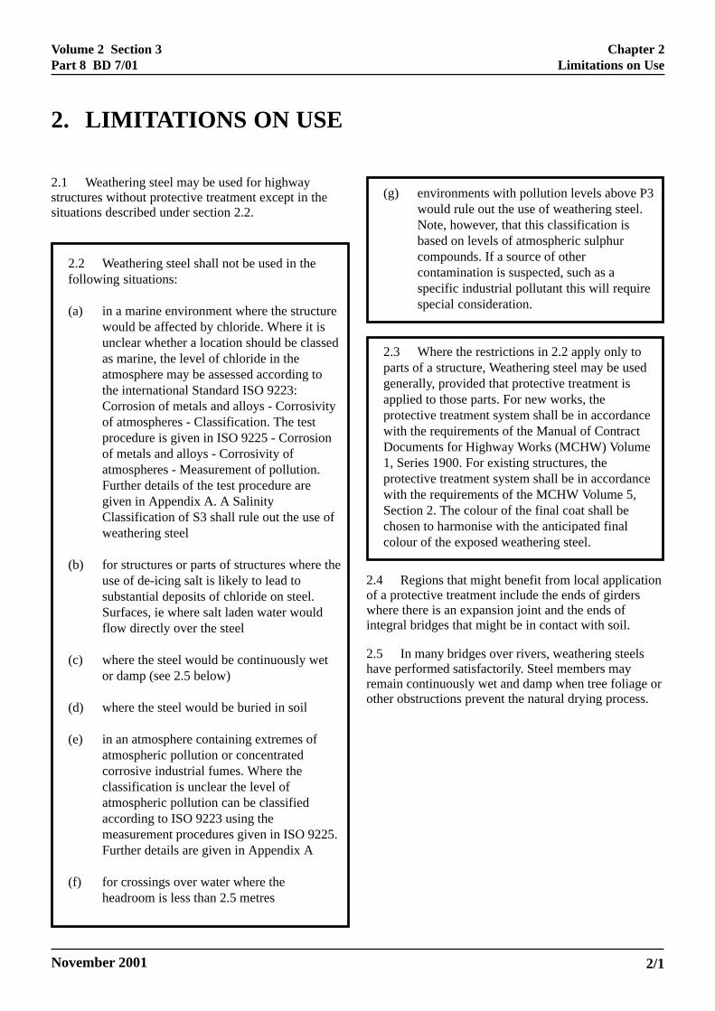
2.1 Weathering steel may be used for highwaystructures without protective treatment except in thesituations described under section 2.2.
2.2 Weathering steel shall not be used in thefollowing situations:
(a) in a marine environment where the structurewould be affected by chloride. Where it isunclear whether a location should be classedas marine, the level of chloride in theatmosphere may be assessed according tothe international Standard ISO 9223:Corrosion of metals and alloys - Corrosivityof atmospheres - Classification. The testprocedure is given in ISO 9225 - Corrosionof metals and alloys - Corrosivity ofatmospheres - Measurement of pollution.Further details of the test procedure aregiven in Appendix A. A SalinityClassification of S3 shall rule out the use ofweathering steel
(b) for structures or parts of structures where theuse of de-icing salt is likely to lead tosubstantial deposits of chloride on steel.Surfaces, ie where salt laden water wouldflow directly over the steel
(c) where the steel would be continuously wetor damp (see 2.5 below)
(d) where the steel would be buried in soil
(e) in an atmosphere containing extremes ofatmospheric pollution or concentratedcorrosive industrial fumes. Where theclassification is unclear the level ofatmospheric pollution can be classifiedaccording to ISO 9223 using themeasurement procedures given in ISO 9225.Further details are given in Appendix A
(f) for crossings over water where theheadroom is less than 2.5 metres
(g) environments with pollution levels above P3would rule out the use of weathering steel.Note, however, that this classification isbased on levels of atmospheric sulphurcompounds. If a source of othercontamination is suspected, such as aspecific industrial pollutant this will requirespecial consideration.
2.3 Where the restrictions in 2.2 apply only toparts of a structure, Weathering steel may be usedgenerally, provided that protective treatment isapplied to those parts. For new works, theprotective treatment system shall be in accordancewith the requirements of the Manual of ContractDocuments for Highway Works (MCHW) Volume1, Series 1900. For existing structures, theprotective treatment system shall be in accordancewith the requirements of the MCHW Volume 5,Section 2. The colour of the final coat shall bechosen to harmonise with the anticipated finalcolour of the exposed weathering steel.
2.4 Regions that might benefit from local applicationof a protective treatment include the ends of girderswhere there is an expansion joint and the ends ofintegral bridges that might be in contact with soil.
2.5 In many bridges over rivers, weathering steelshave performed satisfactorily. Steel members mayremain continuously wet and damp when tree foliage orother obstructions prevent the natural drying process.
Volume 2 Section 3Part 8 BD 7/01
November 2001 3/1
Chapter 3Design - Corrosion Allowances
3. DESIGN - CORROSION ALLOWANCES
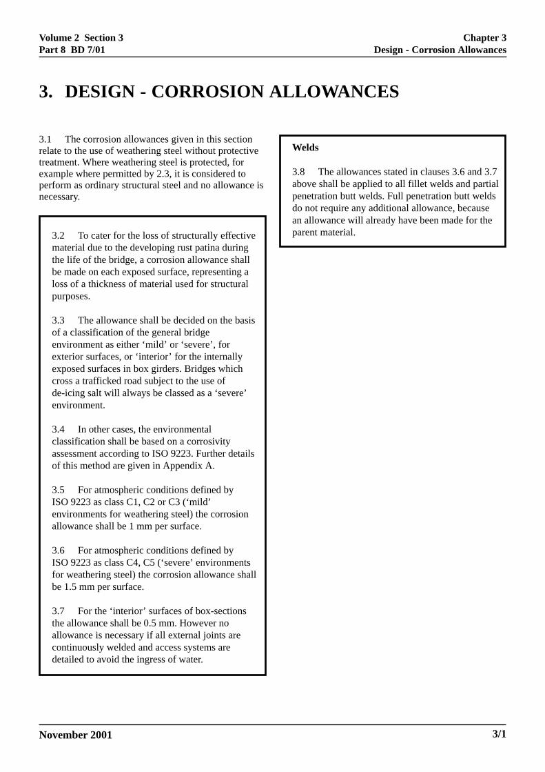
3.1 The corrosion allowances given in this sectionrelate to the use of weathering steel without protectivetreatment. Where weathering steel is protected, forexample where permitted by 2.3, it is considered toperform as ordinary structural steel and no allowance isnecessary.
3.2 To cater for the loss of structurally effectivematerial due to the developing rust patina duringthe life of the bridge, a corrosion allowance shallbe made on each exposed surface, representing aloss of a thickness of material used for structuralpurposes.
3.3 The allowance shall be decided on the basisof a classification of the general bridgeenvironment as either ‘mild’ or ‘severe’, forexterior surfaces, or ‘interior’ for the internallyexposed surfaces in box girders. Bridges whichcross a trafficked road subject to the use ofde-icing salt will always be classed as a ‘severe’environment.
3.4 In other cases, the environmentalclassification shall be based on a corrosivityassessment according to ISO 9223. Further detailsof this method are given in Appendix A.
3.5 For atmospheric conditions defined byISO 9223 as class C1, C2 or C3 (‘mild’environments for weathering steel) the corrosionallowance shall be 1 mm per surface.
3.6 For atmospheric conditions defined byISO 9223 as class C4, C5 (‘severe’ environmentsfor weathering steel) the corrosion allowance shallbe 1.5 mm per surface.
3.7 For the ‘interior’ surfaces of box-sectionsthe allowance shall be 0.5 mm. However noallowance is necessary if all external joints arecontinuously welded and access systems aredetailed to avoid the ingress of water.
Welds
3.8 The allowances stated in clauses 3.6 and 3.7above shall be applied to all fillet welds and partialpenetration butt welds. Full penetration butt weldsdo not require any additional allowance, becausean allowance will already have been made for theparent material.
Volume 2 Section 3Part 8 BD 7/01
November 2001
Chapter 4Design - General Considerations
4/1
4. DESIGN - GENERAL CONSIDERATIONS
Design Standards
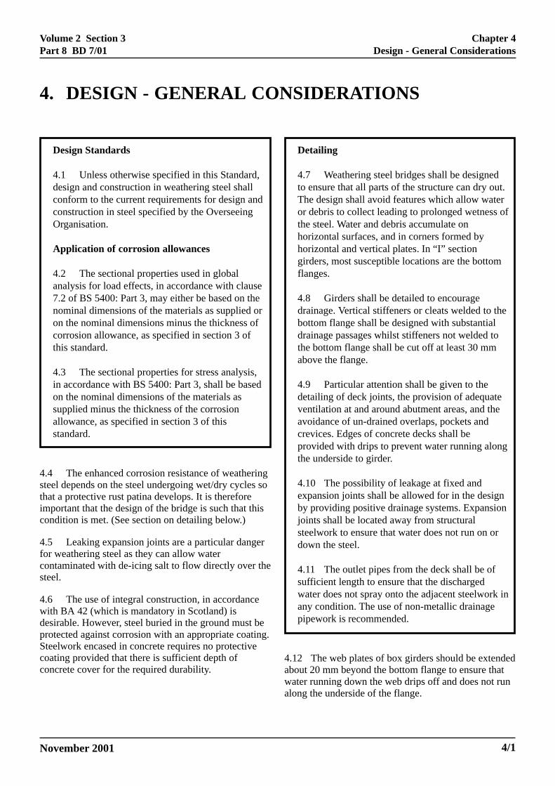
4.1 Unless otherwise specified in this Standard,design and construction in weathering steel shallconform to the current requirements for design andconstruction in steel specified by the OverseeingOrganisation.
Application of corrosion allowances
4.2 The sectional properties used in globalanalysis for load effects, in accordance with clause7.2 of BS 5400: Part 3, may either be based on thenominal dimensions of the materials as supplied oron the nominal dimensions minus the thickness ofcorrosion allowance, as specified in section 3 ofthis standard.
4.3 The sectional properties for stress analysis,in accordance with BS 5400: Part 3, shall be basedon the nominal dimensions of the materials assupplied minus the thickness of the corrosionallowance, as specified in section 3 of thisstandard.
4.4 The enhanced corrosion resistance of weatheringsteel depends on the steel undergoing wet/dry cycles sothat a protective rust patina develops. It is thereforeimportant that the design of the bridge is such that thiscondition is met. (See section on detailing below.)
4.5 Leaking expansion joints are a particular dangerfor weathering steel as they can allow watercontaminated with de-icing salt to flow directly over thesteel.
4.6 The use of integral construction, in accordancewith BA 42 (which is mandatory in Scotland) isdesirable. However, steel buried in the ground must beprotected against corrosion with an appropriate coating.Steelwork encased in concrete requires no protectivecoating provided that there is sufficient depth ofconcrete cover for the required durability.
Detailing
4.7 Weathering steel bridges shall be designedto ensure that all parts of the structure can dry out.The design shall avoid features which allow wateror debris to collect leading to prolonged wetness ofthe steel. Water and debris accumulate onhorizontal surfaces, and in corners formed byhorizontal and vertical plates. In “I” sectiongirders, most susceptible locations are the bottomflanges.
4.8 Girders shall be detailed to encouragedrainage. Vertical stiffeners or cleats welded to thebottom flange shall be designed with substantialdrainage passages whilst stiffeners not welded tothe bottom flange shall be cut off at least 30 mmabove the flange.
4.9 Particular attention shall be given to thedetailing of deck joints, the provision of adequateventilation at and around abutment areas, and theavoidance of un-drained overlaps, pockets andcrevices. Edges of concrete decks shall beprovided with drips to prevent water running alongthe underside to girder.
4.10 The possibility of leakage at fixed andexpansion joints shall be allowed for in the designby providing positive drainage systems. Expansionjoints shall be located away from structuralsteelwork to ensure that water does not run on ordown the steel.
4.11 The outlet pipes from the deck shall be ofsufficient length to ensure that the dischargedwater does not spray onto the adjacent steelwork inany condition. The use of non-metallic drainagepipework is recommended.
4.12 The web plates of box girders should be extendedabout 20 mm beyond the bottom flange to ensure thatwater running down the web drips off and does not runalong the underside of the flange.
Volume 2 Section 3Part 8 BD 7/01
November 20014/2
Chapter 4Design - General Considerations
4.13 A sealant should be provided along the edge ofany interface between weathering steel and concrete.Such locations include the edges of the top flange andthe profile of a beam that is cast into an end wall of anintegral bridge.
4.14 Bi-metallic joints may promote corrosion in localareas when there are significant areas of dissimilarmetals directly coupled to weathering steel structures.However, provided that small components arecompatible or are of ‘more noble’ metal (such asstainless steel bolts in a weathering steel girder) this isnot likely to be a problem.
4.15 Removal of graffiti from weathering steel isdifficult, because the rust patina is somewhat absorbent.Blast cleaning provides a solution, but is costly. Anyother method is unlikely to be visually satisfactory.Consequently, suitable provision should be made in thedesign to prevent or reduce such incidence as far aspossible eg by the use of barriers to prevent access tothe girders.
Volume 2 Section 3Part 8 BD 7/01
November 2001
Welded Connections
5.1 The alloys in weathering steel increase itshardness and this has to be taken into account inselecting the welding procedure. As with any structuralsteel, weld procedures should be formulated either forthe maximum carbon equivalent that could beencountered or with knowledge of the actual carbonequivalents of the materials that are to be used.Specification for welding consumables are defined inManual of Contract Documents for Highway Works,Volume 1 (MCHW1) Specification for Highway Works- Series 1800 Clause 1803.
Bolted connections
5.2 There is a danger of moisture being drawn intocrevices or between steel surfaces in joints of boltedconnections. Any corrosion products which form willhave a greater volume than the original steel and canlead to ‘packout’. It is therefore important that jointsare of adequate tightness and rigidity. This can beensured by keeping within the recommended boltspacing and edge distance requirements in 5.3 below.
5.3 It is recommended that inter-bolt spacings inlines adjacent to plate/section edges should not exceed14 times the thickness of the thinnest component and inany event should not exceed 180 mm. The distancefrom the centre of any bolt to the nearest free edge of aplate should not exceed 8 times the thickness of thethinnest component and in any event should not exceed130 mm.
5.4 In joints where bolt spacings are wider thanrecommended above, or where there are any featuresthought to be at risk from water intake, the joints shouldbe protected by suitable sealants.
5.5 The chemical composition of bolts, nuts andwashers including high strength friction grip bolts,for use with weathering steel structures shallcomply with ASTM A325 Type 3 Grade A orequivalent.
5.6 Load indicating washers are notmanufactured in weathering steel qualities andshall not be used. Alternative means of tightening,such as the half turn method, or bolts torqued to anappropriate design value shall be used.
Surface Treatment
5.7 Where steelwork is marked on its surface foridentification, the marking material shall be suchthat it can be easily and completely removed afterfabrication.
5.8 Surface contamination from concrete,mortar, asphalt, paint, oil and grease shall beprevented, as these have an adverse effect on theformation of a uniform rust patina.
5.9 After fabrication, all exposed surfaces shallbe abrasive blast cleaned to a minimum standard ofSa 2 to ISO 8501-1 (BS 7079 Part A1) to achieve auniform surface. After completion of erection anysurfaces marked or contaminated duringconstruction shall be cleaned to a similar standard.
5.10 Adequate protection shall be providedduring construction against staining of the piersand abutments. This is particularly important incomposite construction before and during theconstruction of the deck slab. During this stageprotective sheeting or equivalent can be used toprotect piers and abutments.
5.11 Wax or grease markers should not be used,because they are difficult to remove and can interferewith the weathering process.
5.12 Blast cleaning is often carried out at thefabrication works, but a final cleaning after site erectionwould assist the formation of a uniform rust patina.
5. CONSTRUCTION
Chapter 5Construction
5/1
Volume 2 Section 3Part 8 BD 7/01
November 2001
Visual Inspection
6.1 Visual examination of the structure forms animportant part of General Inspections.
6.2 For weathering steels, the type and appearance ofthe rust patina provides a useful indication of thecorrosion performance of the weathering steel. Rustpatinas can range from a fine adherent granular type toswelling laminations. In general, an adherent finegrained rust patina is a sign that corrosion isprogressing satisfactorily whilst coarse laminated rustlayers and flakes suggest an unacceptable performance.
6.3 When the appearance is unsatisfactory the visualinspection should be followed by an examination with amagnifying lens to check for flaking or swelling andtaking steel thickness measurements with an ultrasonicinstrument at positions identified at the constructionstage. However, as currently available instruments readonly to the nearest 100 µm meaningful results ofthickness measurements will not be available until thestructure is at least 6 years old.
6.4 General Inspections in accordance withBD 63 (DMRB 3.1.4) shall report the appearanceof the rust patina in terms of adherence and type.Photographs of typical areas will assist inassessing any change in appearance with time.
6.5 The appearance of swelling of the rustpatina indicates that there is a severe localisedcorrosion problem, and in such a case, immediateattention shall be given to identify the cause andtake corrective action.
6.6 Inspections of the weathering steel in criticalareas, particularly in the vicinity of ‘fixed’ and‘expansion’ joints, bolted joints and sealants alongconcrete/weathering steel interfaces shall becarried out at each General Inspection or atintervals not exceeding 2 years.
6.7 Any indication of deck surface waterleakage or wet patches on the weathering steel dueto causes such as faulty drainage or leakingexpansion joints shall be investigated andremedied.
6.8 The accumulation of dirt and debris willencourage corrosion and shall be removed by lowpressure water washing where practical or othermethod approved by the Overseeing Organization.
Corrosion monitoring
6.9 The additional steel thickness specified to allowfor corrosion during the life of the structure is only anestimate. It is important that the actual corrosion rate ofthe structure is monitored to verify that the corrosionallowance will remain adequate. The most appropriatemethod of doing this is to carry out measurements atPrincipal Inspections specified in BD 63 (DMRB 3.1.4)possibly at 6 year intervals. Such inspections shallmeasure residual steel thickness at previously identifiedpoints on the structure. From these measurements, anestimate of the corrosion rate of the steel in thestructure can be made.
6.10 It should be appreciated that corrosion rates varywith time. During the initial period of exposure, thecorrosion rate is governed by the availability of oxygenand water to the steel surface. As the protective patinadevelops and stabilises, the corrosion rate is reduced.The time for the rust patina to become effective incontrolling corrosion depends upon the specificenvironmental conditions.
6.11 A satisfactory method of operating a corrosionmonitoring programme requires the identification ofexact locations for residual thickness measurements atspecified locations critical for strength, or vulnerabilityto joint leakage or condensation.
6.12 Corrosion rates should also be determined afterthe weathering steel has fully developed its protectiverust patina. The rates are expected to be less than 10 µmper year in a ‘mild’ exposed environment in the periodfollowing first few years of exposure.
6. INSPECTION AND MONITORING
Chapter 6Inspection and Monitoring
6/1
Volume 2 Section 3Part 8 BD 7/01
November 2001
6.13 Monitoring locations shall be established atsuitable locations on the bridge steelwork andinitial measurements of residual thickness ofmaterial shall be made at the end of theconstruction period. The initial measurements, atfinal completion of the structure, would indicateactual steel thicknesses, which should be withinthe rolling tolerances from the nominal thickness.These shall be recorded in the MaintenanceManual. Corrosion rates shall be calculated usingsubsequent measurements from the same locations.The position of the monitoring locations shall berecorded in the Maintenance Manual for thestructure with sufficient accuracy so thatsubsequent measurements can be taken at the samelocations.
6.14 The measurements shall be carried out usinga modern digital ultrasonic thickness gauge.Suitable instruments for the purpose are describedin Appendix B. At the Principal Inspection(DMRB 3.1.4 BD 63), measurements of theresidual thicknesses at the monitoring locationsshall be taken and recorded in the MaintenanceManual.
6.15 If projections from a series of measurementstaken after the initial weathering period indicatethat the likely total loss of thickness over thedesign life of the structure would be more than theallowances provided in the design, thenconsideration shall be given to providing a suitableprotective system for the steel at an appropriatetime.
Chapter 6Inspection and Monitoring
6/2
Volume 2 Section 3Part 8 BD 7/01
November 2001
7.1 If in practice it is found that chlorides areadversely affecting the stability of the rust patina andcausing corrosion of the substrate then this can bealleviated by annual cleaning with low-pressure waterwashing at the end of the de-icing period.
7.2 If a weathering steel structure is not performingsatisfactorily, for whatever reason, which may bechanges in the environment or poor design, provision ofadditional corrosion protection will need to beconsidered.
7.3 If painting is deemed necessary either for thewhole structure or only in specific problem areasweathering steels can be protected with the samemaintenance paint systems recommended in theMCHW Volume 5, Section 2.
7.4 The surface preparation necessary will depend onthe protective system to be used and the lifetimerequired.
7.5 To ensure that the paint coating has a long life, itwill be necessary to clean off all existing rust andcontaminants.
7.6 Corrosion on weathering steel can lead to a pittedsurface particularly in the presence of chlorides. Toclean out such pits, wet abrasive blasting isrecommended.
7. MAINTENANCE
Chapter 7Maintenance
7/1
Volume 2 Section 3Part 8 BD 7/01
November 2001
Chapter 8References
8/1
8. REFERENCES
8.1 British Standards Institution
BS EN 10155: 1993 - Structural steels with improvedatmospheric corrosion resistance.
BS EN 10025: 1993 - Hot rolled products of non-alloystructural steels.
BS 7668 - Specification for weldable steels. Hotfinished structural hollow sections in weather resistantsteels.
BS 5400 - Steel, Concrete and Composite Bridges
BS 7079 Part A1 (ISO 8501-1) - Specification for rustgrades and preparation grades of uncoated steelsubstrates and of steel after overall removal of previouscoatings.
8.2 International Standards Organisation
ISO 9223: 1992 (E). Corrosion of metals and alloys -Corrosivity of atmospheres - Classification.
ISO 9224: 1992 (E). Corrosion of metals and alloys -Corrosivity of atmospheres - Guiding values for thecorrosivity categories.
ISO 9225: 1992 (E). Corrosion of metals and alloys -Corrosivity of atmospheres - Measurement of pollution
ISO 9226: 1992 (E). Corrosion of metals and alloys -Corrosivity of atmospheres - Determination ofcorrosion rate of standard specimens for the evaluationof corrosivity.
8.3 Highways Agency Design Manual for Roadsand Bridges (DMRB)
Volume 1 Section 3 General Design
Part 12 - BA 42 - The Design of Integral Bridges.
Volume 3 Section 1 Inspection
Part 4 - BD 63 - Inspection of Highway Structures.
8.4 Highways Agency Manual of ContractDocuments for Highway Works (MCHW)
Volume 1: Specification for Highway Works(MCHW 1) 1900 Series.
Volume 5: Section 2: Maintenance Painting of SteelHighway Structures (MCHW 5).
8.5 Other Publications
Further information on the performance and use ofweathering steel is given in the following documents:
Albrecht P, Coburn SK, Wattar FM, Tinklenberg GLand Gallagher WP (1989) ‘Guidelines for the use ofweathering steel in bridges’ NCHRP Report No 314,Transportation Research Board, National ResearchCouncil, Washington DC, USA.
Albrecht P and Naeemi A H (1984) - Guidelines for theuse of Weathering Steel in Bridges – NCRPR 314 USTransportation Research Board National ResearchCouncil, Washington DC, USA.
British Steel (1996) ‘Weather Resistant Steel: Use andapplications’ British Steel, SP & CS, PO Box 30,Motherwell, Lanarkshire, ML1 1AA.
Brown C W (ISBN 92-9147-000-64) ‘The use ofweathering steel in Bridges’ - Report No 81, EuropeanConvention for Constructional Steelwork.
Halden D (1991) ‘Design and performance ofweathering steel bridges on Scottish trunk roads’ Paper9689, Proceedings, Institution of Civil. Engineers,Part 1, 1991, 90 Apr., 447-462.
Mathay WL (1993) ‘Uncoated weathering steel bridges’Highway structures Design Handbook, Vol. 1, Chapter9, American Institute of Steel Construction, AISCMarketing, 650 Smithfield Street/Suite 750, Pittsburgh,PA 15222-3907, USA.
McKenzie M (1996) ‘The performance of in-situweathering steel in bridges’ - Bridge ManagementForum, Proceedings of the conference, University ofSurrey, Guildford, Surrey, April 2000.
Volume 2 Section 3Part 8 BD 7/01
November 20018/2
Chapter 8References
McKenzie M (1990) ‘The corrosion of weathering steelunder real and simulated bridge decks’ TRRL ResearchReport 233, TRL, Crowthorne Berkshire.
McKenzie M (1978) ‘The corrosion performance ofweathering steel in Highway Bridges’ TRRLLaboratory Report 857, TRRL Crowthorne Berkshire.
ASTM A325 High Strength bolts for Structural SteelJoints.
Volume 2 Section 3Part 8 BD 7/01
November 2001 9/1
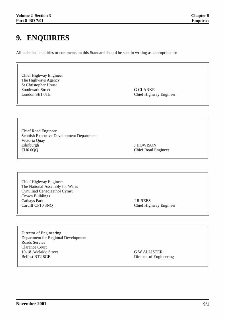
9. ENQUIRIES
All technical enquiries or comments on this Standard should be sent in writing as appropriate to:
Chief Highway EngineerThe Highways AgencySt Christopher HouseSouthwark Street G CLARKELondon SE1 0TE Chief Highway Engineer
Chief Road EngineerScottish Executive Development DepartmentVictoria QuayEdinburgh J HOWISONEH6 6QQ Chief Road Engineer
Chief Highway EngineerThe National Assembly for WalesCynulliad Cenedlaethol CymruCrown BuildingsCathays Park J R REESCardiff CF10 3NQ Chief Highway Engineer
Director of EngineeringDepartment for Regional DevelopmentRoads ServiceClarence Court10-18 Adelaide Street G W ALLISTERBelfast BT2 8GB Director of Engineering
Chapter 9Enquiries
Volume 2 Section 3Part 8 BD 7/01
November 2001
The International Standards Organisation gives amethod for classifying the atmospheric corrosivity withrespect to the main metals used in construction (ISO9223). This adopts two routes to classification - onebased on environmental data and the second oncorrosion tests using test coupons of specific metals.
Classification based on environmentalmeasurements
The following environmental measurements are used:
Yearly time of Wetness (estimated from Time that RH >80% AND temperature is > 0 oC) - categories T1 to T5
Pollution in terms of atmospheric sulphur dioxide levels- categories P0 to P3
The level of sulphur dioxide can be measured usingeither a deposition method or direct volumetricmeasurements of airborne concentration. In thedeposition method, airborne sulphur dioxide reacts withan exposed surface of lead dioxide to form leadsulphate. The quantity is determined by chemicalanalysis. Specimens are usually exposed for a onemonth period, and the testing carried out for a year togive a representative average value.
Pollution in terms of airborne salinity - categories S0 toS3
This is determined by the deposition of airbornechlorides on a specific area of damp muslin exposedunder a specific design of shelter. This device is knownas a ‘wet candle.’ The quantity deposited in a givenperiod, usually one month is determined by chemicalanalysis. Testing is carried out for a year to give arepresentative average value.
The combination of these wetness and pollutionclassifications is used to determine the overallcorrosivity classification - C1 to C5 - for particularmetals. The documents also give guiding values for theexpected corrosion rates within each corrosivitycategory for carbon steel, weathering steel, zinc, copperand aluminium.
Classification based on corrosion rate measurementsof standard specimens
This uses the results of the corrosion rates for standardmetals exposed for a year in a specified manner toclassify the corrosivity.
APPENDIX A - ENVIRONMENTAL CLASSIFICATIONWITH RESPECT TO THE USE OF WEATHERINGSTEEL
A/1
Appendix AEnvironmental Classification with Respect to the Use of Weathering Steel
Volume 2 Section 3Part 8 BD 7/01
November 2001
Traditional ultrasonic thickness gauges measure thetransit time of an ultrasonic signal originating at a probehead placed on one surface of the steel, then reflectedfrom the steel air interface on the other side of thesection back to the probe head. Surface coatings orlayers of rust on the steel will increase the transit timeand give an increased apparent steel thickness. As thesignal speed through the coating or rust is not the sameas through the steel, it is not straightforward to allowfor this. To obtain the steel thickness alone, the surfacecoating or corrosion must be removed prior tomeasurement. The use of such gauges on weatheringsteel structures to monitor residual thickness has thefollowing disadvantages:
(a) The rust layer must be removed withoutremoving any of the underlying steel.
(b) The rust layer has now been removed at thatpoint so will subsequently corrode in a differentmanner from the remainder of the steel. Toestimate ongoing corrosion, furthermeasurements need to be made at a differentposition.
(c) The procedure leads to unsightly blemishes onthe steel surface.
These problems can be overcome by utilising a specialtype of thickness gauge which provides an accuratemeasurement of the residual steel thickness without theneed to remove the rust coating. Instead of measuringthe probe back to probe transit time, the instrumentmeasures the time between echoes within the steelsection. Typical instruments are small, light in weight,battery operated and have a digital display. A couplantmaterial is needed to transmit the signal from the probehead through the rust into the steel. Water or a lighteasily removable material such as glycerol are effectivein doing this.
Such instruments are accurate to +/- 0.1 mm. This isadequate for absolute residual steel thicknessmeasurements for structural calculations. However thislimited accuracy combined with the low corrosion ratesof weathering steels - typically 5 to 15 µm per year -means that estimating corrosion rates from thedifference in thickness readings at different times canonly be done over long time periods.
Because the rust coating does not need to be removed,steel thickness can be measured at exactly the sameposition at different times.
APPENDIX B - RESIDUAL STEEL THICKNESSMEASUREMENT USING ULTRASONIC GAUGES
B/1
Appendix BResidual Steel Thickness Measurement Using Ultrasonic Gauges


Ionad Ghnó Gheata na
Páirce,
Stráid Gheata na Páirce, Baile Átha Cliath 8, Éire
www.tii.ie
+353 (01) 646 3600
Parkgate Business Centre,
Parkgate Street,
Dublin 8, Ireland
+353 (01) 646 3601