Embed Size (px)
Citation preview
VTE/03/2002
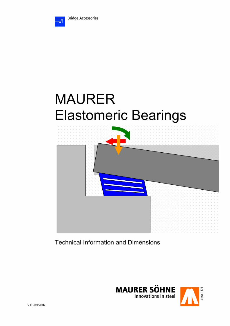
MAURER Elastomeric Bearings
Technical Information and Dimensions

Structure Reinforced elastomeric bearings are an often used type of bridge bearings and already been installed in many kinds of structures all over the world. Depending on the area of application and country requirements MAURER elastomeric bearings can be supplied in accordance with various standards, e.g. EN1337-3, DIN 4141-14, BS5400, AASHTO, SETRA etc. (see annex 15 for specification of standards). The reinforced elastomeric bearings, so called laminated bearings, are built of different layers, i.e. a layer of synthetic chloroprene rubber (CR) or natural rubber (NR) resp. and a steel re-inforcing sheet follows the next. These laminated material layers will merge by vulcanising to a single pad. The rubber bonds to the steel reinforcing plates. This connection is resistant to tension, compression and shear while load is applied onto the bearing. Basically there are three different reinforced types of elastomeric bearings: �� type 1:
The bearing is totally covered with rubber.
�� type 2:
The bearing can be secured against horizontal sliding by means of shear dowels for example. For this an anchor plate will be vulcanised onto the bearing upper and lower surface.
�� type 5:
Checkered steel sheets are vulcanised onto the upper and lower pad surface. The layer structure corresponds to the type 2 bearing.
The elastomeric bearings are available in rectangular, square and circular shape. Mixed types like type 1/2 are also possible. On the annex 1.1 to 1.4 the DIN bearing types and sizes are summarized. On annex 2 the standard pad sizes according to EN-1337-3 are shown. On request MAURER can supply any other sizes also. Structural movements or rotations within certain limits are transmitted by shear strain of the rubber, which however results in restoring forces or moments.
Function The usual load range lies between 100 kN and 18,000 kN. MAURER elastomeric bearings can be fitted with additional steel plates and restraints. In general three different types are used: �� V2 (annex 3):
The elastomeric bearings of type 1 and 2 are set between steel plates. The type 1 bearing is not anchored, the type 2 bearing is anchored by a shear disc to the plates (see sketch on the left) to prevent horizontal sliding. Both steel plates can be fitted with four cast in concrete shear studs as well. The V2 is free-deforming in all directions.
�� V1 (annex 4):
In order to block horizontal structural movements steel restraints are welded to the steel plates of the above mentioned V2. The V1 is deforming in one direction and is transmitting horizontal forces in the other direction.
�� V (annex 5):
Similar to the V1, restraints are blocking the horizontal movements, but in any horizontal direction now. The V is transmitting horizontal forces in any direction.
The above elastomeric bearings V2 and V1 are supplied with an additional sliding plate, if the horizontal structural movements exceed the rubber design limits. The sketch on the left lower edge shows a VE2 bearing, sliding in one direction and deforming in the other. In addition to the MAURER standard elastomeric bearings, also special bearings like for seismic isolation and damping respectively (annex 6) can be supplied. To fulfil approval requirements MAURER has implemented several supervision tools and can also conduct load + shear testing of the elastomeric bearings (annex 7). All MAURER reinforced elastomeric bearing types and steel parts are custom-made. From there it´s possible to supply any special shape and size on request.
Type 2: Like type 1 but with vulcanised anchor steel plates
Type 1: Unanchored reinforced elastomeric bearing
Type 5: Like type 2 but with checkered steel plates
VE2: Type V2 bearing & uni-directional sliding plate on top
V2: Type 1 or 2 bearing between additional anchor plates

ANNEX 1.1 MAURER - Laminated Elastomeric Bearings in accordance with German Standard DIN 4141, section 14
Minimum Pressure
� 3 N/mm² Minimum Pressure
< 3 N/mm²
Type 1 Type 2 Type 1/2 Type 5
Vert
ical
Loa
d
Dim
ensi
on
Elas
tom
eric
Lay
ers
Dis
plac
emen
t ±
Bea
ring
Thic
knes
s
Rub
ber T
hick
ness
Dis
plac
emen
t ±
Bea
ring
Thic
knes
s
Rub
ber T
hick
ness
Dis
plac
emen
t ±
Bea
ring
Thic
knes
s
Rub
ber T
hick
ness
Dis
plac
emen
t ±
Bea
ring
Thic
knes
s
Rub
ber T
hick
ness
rota
tion �
rota
tion
Ø
MN mm nos. mm mm mm mm
1/1000 1/1000
1 7,0 14 10 – – – – – – – – – 4 –
0,10 100 x 100 2 10,5 21 15 7,0 42 10 8,8 31,5 12,5 7,0 32 10 8 – 0,15 100 x 150 3 14,0 28 20 10,5 49 15 12,3 38,5 17,5 10,5 39 15 12 – 0,20 100 x 200 4 16,3 35 25 14,0 56 20 15,2 45,5 22,5 14,0 46 20 16 –
5 18,0 42 30 16,3 63 25 17,2 52,5 27,5 16,3 53 25 20 – 6 – – – 18,0 70 30 – – – 18,0 60 30 24 – 1 7,0 14 10 – – – – – – – – – 3 –
2 10,5 21 15 7,0 42 10 8,8 31,5 12,5 7,0 32 10 6 – 3 14,0 28 20 10,5 49 15 12,3 38,5 17,5 10,5 39 15 9 –
4 17,5 35 25 14,0 56 20 15,8 45,5 22,5 14,0 46 20 12 – 0,30 150 x 200 5 21,0 42 30 17,5 63 25 19,3 52,5 27,5 17,5 53 25 15 –
6 23,3 49 35 21,0 70 30 22,2 59,5 32,5 21,0 60 30 18 – 7 25,3 56 40 23,3 77 35 24,4 66,5 37,5 23,3 67 35 21 – 8 27,0 63 45 25,3 84 40 26,2 73,5 42,5 25,3 74 40 24 – 9 28,3 70 50 27,0 91 45 27,7 80,5 47,5 27,0 81 45 27 – 10 – – – 28,3 98 50 – – – 28,3 88 50 30 –
Dimensions of plan area (intermediate dimensions and over-sizes available)
Permissible vertical load onto the bearing
Permissible rotation: - rectangular bearing => around parallel axis to longer edge in plan - round bearing => around any horizontal axis
Number of elastomeric layers
Permissible shear displacement between the super- and substructure
Thickness of unloaded bearing
Minimum pressure for safety against slipping
Type 1 Type 2 Type 1/2 Type 5
Reinforcing steel sheets are totally covered with rubber. The bearing is not anchored neither to super- nor to substructure.
Upper and lower bearing surface can be anchored by dowels, bolts, etc. to super- or to substructure.
Upper or lower bearing surface can be anchored by dowels, bolts, etc. to super- or to substructure. One contact surface is unanchored.
Upper and lower bearing surface are fitted with checkered steel sheets for surface anchorage to super- and to substructure.
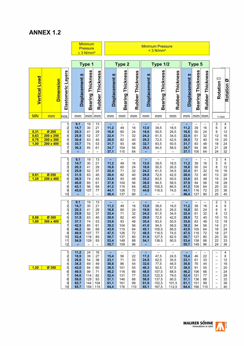
ANNEX 1.2
Minimum Pressure � 3 N/mm²
Minimum Pressure < 3 N/mm²
Type 1 Type 2 Type 1/2 Type 5
Vert
ical
Loa
d
Dim
ensi
on
Elas
tom
eric
Lay
ers
Dis
plac
emen
t ±
Bea
ring
Thic
knes
s
Rub
ber T
hick
ness
Dis
plac
emen
t ±
Bea
ring
Thic
knes
s
Rub
ber T
hick
ness
Dis
plac
emen
t ±
Bea
ring
Thic
knes
s
Rub
ber T
hick
ness
Dis
plac
emen
t ±
Bea
ring
Thic
knes
s
Rub
ber T
hick
ness
R
otat
ion �
Rot
atio
n Ø
MN mm nos. mm mm mm mm mm mm mm mm mm mm mm mm 1/1000
1 9,1 19 13 – – – – – – – – – 3 4 2 14,7 30 21 11,2 49 16 13,0 39,5 18,5 11,2 39 16 6 8
0,31 Ø 200 3 20,3 41 29 16,8 60 24 18,6 50,5 26,5 16,8 50 24 9 12 0,63 200 x 250 4 25,9 52 37 22,4 71 32 24,2 61,5 34,5 22,4 61 32 12 16 0,75 200 x 300 5 30,4 63 45 28,0 82 40 29,2 72,5 42,5 28,0 72 40 15 20 1,00 200 x 400 6 33,7 74 53 31,7 93 48 32,7 83,5 50,5 31,7 83 48 18 24
7 36,3 85 61 34,7 104 56 35,5 94,5 58,5 34,7 94 56 21 28 8 – – – 37,1 115 64 – – – 37,1 105 64 24 32 1 9,1 19 13 – – – – – – – – – 3 4
2 14,7 30 21 11,2 49 16 13,0 39,5 18,5 11,2 39 16 5 8 3 20,3 41 29 16,8 60 24 18,6 50,5 26,5 16,8 50 24 8 12 4 25,9 52 37 22,4 71 32 24,2 61,5 34,5 22,4 61 32 10 16
0,61 Ø 250 5 31,5 63 45 28,0 82 40 29,8 72,5 42,5 28,0 72 40 13 20 1,25 250 x 400 6 36,5 74 53 33,6 93 48 35,2 83,5 50,5 33,6 83 48 15 24
7 40,0 85 61 37,9 104 56 39,0 94,5 58,5 37,9 94 56 18 28 8 43,1 96 69 41,2 115 64 42,2 105,5 66,5 41,2 105 64 20 32 9 45,6 107 77 44,1 126 72 44,8 116,5 74,5 44,1 116 72 23 36 10 – – – 46,4 137 80 – – – 46,4 127 80 25 40 1 9,1 19 13 – – – – – – – – – 2 3
2 14,7 30 21 11,2 49 16 13,0 39,5 18,5 11,2 39 16 4 6 3 20,3 41 29 16,8 60 24 18,6 50,5 26,5 16,8 50 24 6 9 4 25,9 52 37 22,4 71 32 24,2 61,5 34,5 22,4 61 32 8 12
0,88 Ø 300 5 31,5 63 45 28,0 82 40 29,8 72,5 42,5 28,0 72 40 10 15 1,80 300 x 400 6 37,1 74 53 33,6 93 48 35,4 83,5 50,5 33,6 83 48 12 18
7 42,5 85 61 39,2 104 56 41,0 94,5 58,5 39,2 94 56 14 21 8 46,2 96 69 43,9 115 64 45,1 105,5 66,5 43,9 105 64 16 24 9 49,5 107 77 47,5 126 72 48,5 116,5 74,5 47,5 116 72 18 27 10 52,4 118 85 50,7 137 80 51,6 127,5 82,5 50,7 127 80 20 30 11 54,9 129 93 53,4 148 88 54,1 138,5 90,5 53,4 138 88 22 33 12 – – – 55,7 159 96 – – – 55,7 149 96 24 36 1 11,2 24 16 – – – – – – – – – – 4
2 18,9 39 27 15,4 56 22 17,2 47,5 24,5 15,4 46 22 – 8 3 26,6 54 38 23,1 71 33 24,9 62,5 35,5 23,1 61 33 – 12 4 34,3 69 49 30,8 86 44 32,6 77,5 46,5 30,8 76 44 – 16
1,20 Ø 350 5 42,0 84 60 38,5 101 55 40,3 92,5 57,5 38,5 91 55 – 20 6 49,5 99 71 46,2 116 66 48,0 107,5 68,5 46,2 106 66 – 24 7 54,6 114 82 52,4 131 77 53,5 122,5 79,5 52,4 121 77 – 28
8 59,0 129 93 57,1 146 88 58,0 137,5 90,5 57,1 136 88 – 32 9 62,7 144 104 61,1 161 99 61,9 152,5 101,5 61,1 151 99 – 36 10 65,7 159 115 64,4 176 110 65,1 167,5 112,5 64,4 166 110 – 40
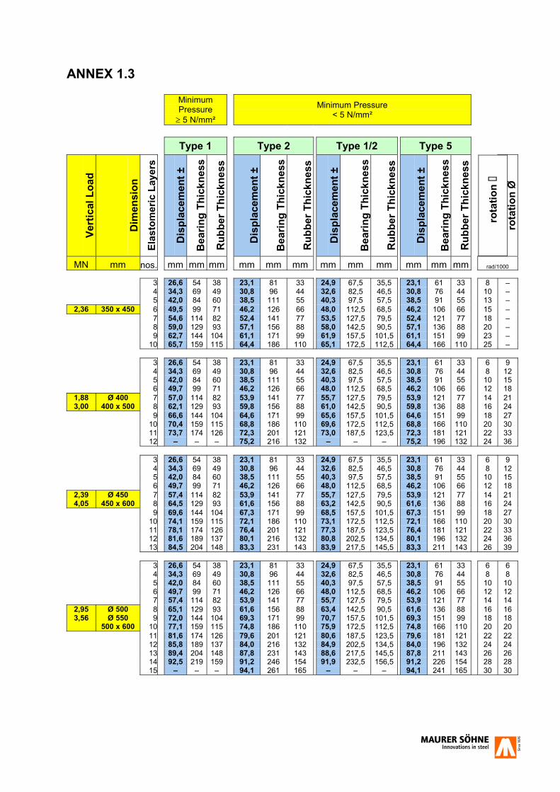
ANNEX 1.3
Minimum Pressure � 5 N/mm²
Minimum Pressure < 5 N/mm²
Type 1 Type 2 Type 1/2 Type 5
Vert
ical
Loa
d
Dim
ensi
on
Elas
tom
eric
Lay
ers
Dis
plac
emen
t ±
Bea
ring
Thic
knes
s
Rub
ber T
hick
ness
Dis
plac
emen
t ±
Bea
ring
Thic
knes
s
Rub
ber T
hick
ness
Dis
plac
emen
t ±
Bea
ring
Thic
knes
s
Rub
ber T
hick
ness
Dis
plac
emen
t ±
Bea
ring
Thic
knes
s
Rub
ber T
hick
ness
ro
tatio
n �
rota
tion
Ø
MN mm nos. mm mm mm mm mm mm mm mm mm mm mm mm rad/1000
3 26,6 54 38 23,1 81 33 24,9 67,5 35,5 23,1 61 33 8 – 4 34,3 69 49 30,8 96 44 32,6 82,5 46,5 30,8 76 44 10 – 5 42,0 84 60 38,5 111 55 40,3 97,5 57,5 38,5 91 55 13 –
2,36 350 x 450 6 49,5 99 71 46,2 126 66 48,0 112,5 68,5 46,2 106 66 15 – 7 54,6 114 82 52,4 141 77 53,5 127,5 79,5 52,4 121 77 18 – 8 59,0 129 93 57,1 156 88 58,0 142,5 90,5 57,1 136 88 20 – 9 62,7 144 104 61,1 171 99 61,9 157,5 101,5 61,1 151 99 23 –
10 65,7 159 115 64,4 186 110 65,1 172,5 112,5 64,4 166 110 25 – 3 26,6 54 38 23,1 81 33 24,9 67,5 35,5 23,1 61 33 6 9
4 34,3 69 49 30,8 96 44 32,6 82,5 46,5 30,8 76 44 8 12 5 42,0 84 60 38,5 111 55 40,3 97,5 57,5 38,5 91 55 10 15 6 49,7 99 71 46,2 126 66 48,0 112,5 68,5 46,2 106 66 12 18
1,88 Ø 400 7 57,0 114 82 53,9 141 77 55,7 127,5 79,5 53,9 121 77 14 21 3,00 400 x 500 8 62,1 129 93 59,8 156 88 61,0 142,5 90,5 59,8 136 88 16 24
9 66,6 144 104 64,6 171 99 65,6 157,5 101,5 64,6 151 99 18 27 10 70,4 159 115 68,8 186 110 69,6 172,5 112,5 68,8 166 110 20 30 11 73,7 174 126 72,3 201 121 73,0 187,5 123,5 72,3 181 121 22 33 12 – – – 75,2 216 132 – – – 75,2 196 132 24 36 3 26,6 54 38 23,1 81 33 24,9 67,5 35,5 23,1 61 33 6 9
4 34,3 69 49 30,8 96 44 32,6 82,5 46,5 30,8 76 44 8 12 5 42,0 84 60 38,5 111 55 40,3 97,5 57,5 38,5 91 55 10 15 6 49,7 99 71 46,2 126 66 48,0 112,5 68,5 46,2 106 66 12 18
2,39 Ø 450 7 57,4 114 82 53,9 141 77 55,7 127,5 79,5 53,9 121 77 14 21 4,05 450 x 600 8 64,5 129 93 61,6 156 88 63,2 142,5 90,5 61,6 136 88 16 24
9 69,6 144 104 67,3 171 99 68,5 157,5 101,5 67,3 151 99 18 27 10 74,1 159 115 72,1 186 110 73,1 172,5 112,5 72,1 166 110 20 30 11 78,1 174 126 76,4 201 121 77,3 187,5 123,5 76,4 181 121 22 33 12 81,6 189 137 80,1 216 132 80,8 202,5 134,5 80,1 196 132 24 36 13 84,5 204 148 83,3 231 143 83,9 217,5 145,5 83,3 211 143 26 39 3 26,6 54 38 23,1 81 33 24,9 67,5 35,5 23,1 61 33 6 6
4 34,3 69 49 30,8 96 44 32,6 82,5 46,5 30,8 76 44 8 8 5 42,0 84 60 38,5 111 55 40,3 97,5 57,5 38,5 91 55 10 10 6 49,7 99 71 46,2 126 66 48,0 112,5 68,5 46,2 106 66 12 12 7 57,4 114 82 53,9 141 77 55,7 127,5 79,5 53,9 121 77 14 14
2,95 Ø 500 8 65,1 129 93 61,6 156 88 63,4 142,5 90,5 61,6 136 88 16 16 3,56 Ø 550 9 72,0 144 104 69,3 171 99 70,7 157,5 101,5 69,3 151 99 18 18
500 x 600 10 77,1 159 115 74,8 186 110 75,9 172,5 112,5 74,8 166 110 20 20 11 81,6 174 126 79,6 201 121 80,6 187,5 123,5 79,6 181 121 22 22 12 85,8 189 137 84,0 216 132 84,9 202,5 134,5 84,0 196 132 24 24 13 89,4 204 148 87,8 231 143 88,6 217,5 145,5 87,8 211 143 26 26 14 92,5 219 159 91,2 246 154 91,9 232,5 156,5 91,2 226 154 28 28 15 – – – 94,1 261 165 – – – 94,1 241 165 30 30
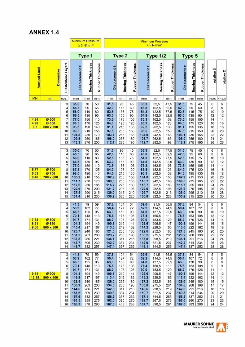
ANNEX 1.4
Minimum Pressure
� 5 N/mm² Minimum Pressure
< 5 N/mm²
Type 1 Type 2 Type 1/2 Type 5
Vert
ical
Loa
d
Dim
ensi
on
Elas
tom
eric
Lay
ers
Dis
plac
emen
t ±
Bea
ring
Thic
knes
s
Rub
ber T
hick
ness
Dis
plac
emen
t ±
Bea
ring
Thic
knes
s
Rub
ber T
hick
ness
Dis
plac
emen
t ±
Bea
ring
Thic
knes
s
Rub
ber T
hick
ness
Dis
plac
emen
t ±
Bea
ring
Thic
knes
s
Rub
ber T
hick
ness
ro
tatio
n �
rota
tion
Ø
MN mm nos. mm mm mm mm mm mm mm mm mm mm mm mm 1/1000 1/1000
3 35,0 70 50 31,5 95 45 33,3 82,5 47,5 31,5 75 45 6 6 4 45,5 90 65 42,0 115 60 43,8 102,5 62,5 42,0 95 60 8 8 5 56,0 110 80 52,5 135 75 54,3 122,5 77,5 52,5 115 75 10 10 6 66,5 130 95 63,0 155 90 64,8 142,5 92,5 63,0 135 90 12 12
4,24 Ø 600 7 77,0 150 110 73,5 175 105 75,3 162,5 108 73,5 155 105 14 14 4,98 Ø 650 8 86,5 170 125 84,0 195 120 85,2 182,5 123 84,0 175 120 16 16 6,3 600 x 700 9 93,3 190 140 91,1 215 135 92,2 202,5 138 91,1 195 135 18 18
10 99,5 210 155 97,5 235 150 98,5 222,5 153 97,5 215 150 20 20 11 104,8 230 170 103,1 255 165 104,0 242,5 168 103,1 235 165 22 22 12 109,5 250 185 108,0 275 180 108,7 262,5 183 108,0 255 180 24 24
13 113,3 270 200 112,1 295 195 112,7 282,5 198 112,1 275 195 26 26 3 35,0 70 50 31,5 95 45 33,3 82,5 47,5 31,5 75 45 6 6
4 45,5 90 65 42,0 115 60 43,8 102,5 62,5 42,0 95 60 8 8 5 56,0 110 80 52,5 135 75 54,3 122,5 77,5 52,5 115 75 10 10 6 66,5 130 95 63,0 155 90 64,8 142,5 92,5 63,0 135 90 12 12 7 77,0 150 110 73,5 175 105 75,3 162,5 108 73,5 155 105 14 14
5,77 Ø 700 8 87,5 170 125 84,0 195 120 85,8 182,5 123 84,0 175 120 16 16 6,63 Ø 750 9 98,0 190 140 94,5 215 135 96,3 202,5 138 94,5 195 135 18 18 8,40 700 x 800 10 105,2 210 155 102,9 235 150 104,0 222,5 153 102,9 215 150 20 20
11 111,7 230 170 109,6 255 165 110,7 242,5 168 109,6 235 165 22 22 12 117,6 250 185 115,7 275 180 116,7 262,5 183 115,7 255 180 24 24 13 122,9 270 200 121,2 295 195 122,0 282,5 198 121,2 275 195 26 26 14 127,5 290 215 126,0 315 210 126,7 302,5 213 126,0 295 210 28 28 15 131,4 310 230 130,2 335 225 130,8 322,5 228 130,2 315 225 30 30 3 41,3 79 59 37,8 104 54 39,6 91,5 56,5 37,8 84 54 6 6
4 53,9 102 77 50,4 127 72 52,2 114,5 74,5 50,4 107 72 8 8 5 66,5 125 95 63,0 150 90 64,8 137,5 92,5 63,0 130 90 10 10 6 79,1 148 113 75,6 173 108 77,4 160,5 111 75,6 153 108 12 12
7,54 Ø 800 7 91,7 171 131 88,2 196 126 90,0 183,5 129 88,2 176 126 14 14 8,51 Ø 850 8 104,3 194 149 100,8 219 144 102,6 206,5 147 100,8 199 144 16 16 9,60 800 x 800 9 115,4 217 167 113,0 242 162 114,2 229,5 165 113,0 222 162 18 18
10 123,7 240 185 121,5 265 180 122,6 252,5 183 121,5 245 180 20 20 11 131,2 263 203 129,2 288 198 130,2 275,5 201 129,2 268 198 22 22 12 137,8 286 221 136,1 311 216 137,0 298,5 219 136,1 291 216 24 24 13 143,7 309 239 142,2 334 234 142,9 321,5 237 142,2 314 234 26 26 14 148,7 332 257 147,4 357 252 148,1 344,5 255 147,4 337 252 28 28 3 41,3 79 59 37,8 104 54 39,6 91,5 56,5 37,8 84 54 5 5
4 53,9 102 77 50,4 127 72 52,2 114,5 74,5 50,4 107 72 6 6 5 66,5 125 95 63,0 150 90 64,8 137,5 92,5 63,0 130 90 8 8 6 79,1 148 113 75,6 173 108 77,4 160,5 111 75,6 153 108 9 9 7 91,7 171 131 88,2 196 126 90,0 183,5 129 88,2 176 126 11 11
9,54 Ø 900 8 104,3 194 149 100,8 219 144 102,6 206,5 147 100,8 199 144 12 12 12,15 900 x 900 9 116,9 217 167 113,4 242 162 115,2 229,5 165 113,4 222 162 14 14
10 128,5 240 185 126,0 265 180 127,2 252,5 183 126,0 245 180 15 15 11 136,9 263 203 134,6 288 198 135,8 275,5 201 134,6 268 198 17 17 12 144,6 286 221 142,6 311 216 143,6 298,5 219 142,6 291 216 18 18 13 151,6 309 239 149,8 334 234 150,7 321,5 237 149,8 314 234 20 20 14 157,9 332 257 156,2 357 252 157,1 344,5 255 156,2 337 252 21 21 15 163,5 355 275 162,0 380 270 162,7 367,5 273 162,0 360 270 23 23 16 168,3 378 293 167,0 403 288 167,7 390,5 291 167,0 383 288 24 24
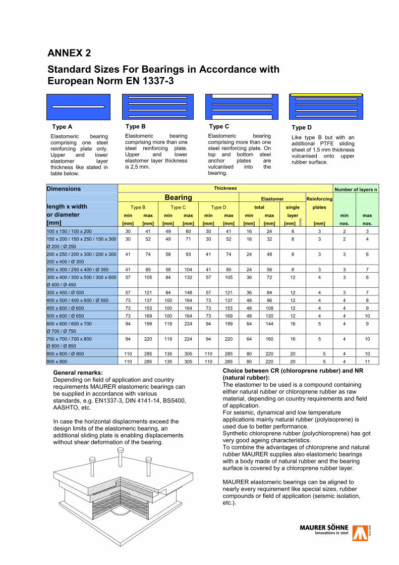
ANNEX 2
Standard Sizes For Bearings in Accordance with European Norm EN 1337-3
Dimensions Thickness Number of layers n
Bearing Elastomer Reinforcing length x width Type B Type C Type D total single plates or diameter min max min max min max min max layer min max [mm] [mm] [mm] [mm] [mm] [mm] [mm] [mm] [mm] [mm] [mm] nos. nos. 100 x 150 / 100 x 200 30 41 49 60 30 41 16 24 8 3 2 3 150 x 200 / 150 x 250 / 150 x 300 30 52 49 71 30 52 16 32 8 3 2 4 Ø 200 / Ø 250 200 x 250 / 200 x 300 / 200 x 300 41 74 58 93 41 74 24 48 8 3 3 6 200 x 400 / Ø 300 250 x 300 / 250 x 400 / Ø 350 41 85 58 104 41 85 24 56 8 3 3 7 300 x 400 / 300 x 500 / 300 x 600 57 105 84 132 57 105 36 72 12 4 3 6 Ø 400 / Ø 450 350 x 450 / Ø 500 57 121 84 148 57 121 36 84 12 4 3 7 400 x 500 / 400 x 600 / Ø 550 73 137 100 164 73 137 48 96 12 4 4 8 450 x 600 / Ø 600 73 153 100 164 73 153 48 108 12 4 4 9 500 x 600 / Ø 650 73 169 100 164 73 169 48 120 12 4 4 10 600 x 600 / 600 x 700 94 199 119 224 94 199 64 144 16 5 4 9 Ø 700 / Ø 750 700 x 700 / 700 x 800 94 220 119 224 94 220 64 160 16 5 4 10 Ø 800 / Ø 850 800 x 800 / Ø 900 110 285 135 305 110 285 80 220 20 5 4 10 900 x 900 110 285 135 305 110 285 80 220 20 5 4 11
Type B Type C Type D Type A Elastomeric bearing comprising one steel reinforcing plate only. Upper and lower elastomer layer thickness like stated in table below.
Elastomeric bearingcomprising more than one steel reinforcing plate.Upper and lowerelastomer layer thicknessis 2,5 mm.
Elastomeric bearing comprising more than one steel reinforcing plate. On top and bottom steel anchor plates are vulcanised into the bearing.
Like type B but with an additional PTFE sliding sheet of 1,5 mm thickness vulcanised onto upper rubber surface.
General remarks: Depending on field of application and country requirements MAURER elastomeric bearings can be supplied in accordance with various standards, e.g. EN1337-3, DIN 4141-14, BS5400, AASHTO, etc. In case the horizontal displacments exceed the design limits of the elastomeric bearing, an additional sliding plate is enabling displacements without shear deformation of the bearing.
Choice between CR (chloroprene rubber) and NR (natural rubber): The elastomer to be used is a compound containing either natural rubber or chloroprene rubber as raw material, depending on country requirements and field of application. For seismic, dynamical and low temperature applications mainly natural rubber (polyisoprene) is used due to better performance. Synthetic chloroprene rubber (polychloroprene) has got very good ageing characteristics. To combine the advantages of chloroprene and natural rubber MAURER supplies also elastomeric bearings with a body made of natural rubber and the bearing surface is covered by a chloroprene rubber layer. MAURER elastomeric bearings can be aligned to nearly every requirement like special sizes, rubber compounds or field of application (seismic isolation, etc.).
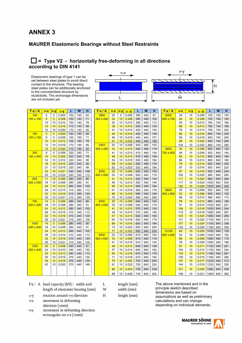
ANNEX 3 MAURER Elastomeric Bearings without Steel Restraints = Type V2 - horizontally free-deforming in all directions according to DIN 4141 F-z / A v-x v-y �-y L W H F-z / A v-x v-y � -y L W H F-z / A v-x v-y � -y L W H
100 5 5 0,004 150 140 64 1800 20 5 0,006 390 440 91 6300 34 10 0,006 720 740 120 100 x 100 9 5 0,008 150 140 71 300 x 400 24 10 0,008 390 440 102 600 x 700 44 10 0,008 720 740 140
10 10 0,012 150 140 78 30 10 0,010 390 440 113 55 10 0,010 780 740 160 13 10 0,016 170 140 85 36 10 0,012 420 440 124 66 10 0,012 780 740 180 15 10 0,020 170 140 92 41 10 0,014 420 440 135 76 10 0,014 780 740 200
150 5 5 0,004 150 190 64 45 10 0,016 420 440 146 86 10 0,016 840 740 220 100 x 150 9 5 0,008 150 190 71 49 10 0,018 440 440 157 93 10 0,018 840 740 240
10 10 0,012 150 190 78 51 10 0,020 440 440 168 99 10 0,020 840 740 260 13 10 0,016 170 190 85 2363 25 10 0,008 440 490 104 104 10 0,022 860 740 280 15 10 0,020 170 190 92 350 x 450 33 10 0,010 440 490 119 8400 34 10 0,006 820 840 120
300 9 5 0,006 220 240 71 41 10 0,013 470 490 134 700 x 800 44 10 0,008 820 840 140 150 x 200 10 10 0,009 220 240 78 48 10 0,015 470 490 149 55 10 0,010 860 840 160
14 10 0,012 220 240 85 54 10 0,018 520 490 164 66 10 0,012 860 840 180 18 10 0,015 220 240 92 58 10 0,020 520 490 179 76 10 0,014 920 840 200 21 10 0,018 220 240 99 62 10 0,023 520 490 194 87 10 0,016 920 840 220 23 10 0,021 240 240 106 3000 25 10 0,006 520 540 104 97 10 0,018 920 840 240 25 10 0,024 240 240 113 400 x 500 33 10 0,008 520 540 119 105 10 0,020 960 840 260
625 11 10 0,006 280 290 80 41 10 0,010 520 540 134 111 10 0,022 960 840 280 200 x 250 18 10 0,009 280 290 91 49 10 0,012 520 540 149 117 10 0,024 1000 840 300
24 10 0,012 280 290 102 56 10 0,014 560 540 164 122 10 0,026 1000 840 320 29 10 0,015 310 290 113 61 10 0,016 560 540 179 9600 40 10 0,006 930 840 129 32 10 0,018 310 290 124 66 10 0,018 590 540 194 800 x 800 53 10 0,008 930 840 152 35 10 0,021 310 290 135 70 10 0,020 590 540 209 66 10 0,010 980 840 175
750 14 5 0,006 280 340 80 4050 25 10 0,006 540 640 104 78 10 0,012 980 840 198 200 x 300 18 10 0,009 280 340 91 450 x 600 33 10 0,008 540 640 119 91 10 0,014 1030 840 221
24 10 0,012 280 340 102 41 10 0,010 570 640 134 104 10 0,016 1030 840 244 29 10 0,015 310 340 113 49 10 0,012 570 640 149 115 10 0,018 1080 840 267 32 10 0,018 310 340 124 57 10 0,014 620 640 164 123 10 0,020 1080 840 290 35 10 0,021 310 340 135 64 10 0,016 620 640 179 131 10 0,022 1130 840 313
1000 14 5 0,006 280 440 80 69 10 0,018 620 640 194 137 10 0,024 1130 840 336 200 x 400 18 10 0,009 280 440 91 73 10 0,020 650 640 209 143 10 0,026 1160 840 359
24 10 0,012 280 440 102 77 10 0,022 650 640 224 12150 40 10 0,005 1030 940 129 29 10 0,015 310 440 113 4500 25 10 0,006 610 640 104 900 x 900 53 10 0,006 1030 940 152 32 10 0,018 310 440 124 500 x 600 33 10 0,008 610 640 119 66 10 0,008 1080 940 175 35 10 0,021 310 440 135 41 10 0,010 610 640 134 78 10 0,009 1080 940 198
1250 20 5 0,008 340 440 91 49 10 0,012 640 640 149 91 10 0,011 1130 940 221 250 x 400 24 10 0,010 340 440 102 57 10 0,014 640 640 164 104 10 0,012 1130 940 244
30 10 0,013 340 440 113 64 10 0,016 670 640 179 116 10 0,014 1180 940 267 35 10 0,015 370 440 124 71 10 0,018 670 640 194 128 10 0,015 1180 940 290 39 10 0,018 370 440 135 76 10 0,020 700 640 209 137 10 0,017 1230 940 313 42 10 0,020 370 440 146 81 10 0,022 700 640 224 144 10 0,018 1230 940 336
85 10 0,024 730 640 239 151 10 0,020 1280 940 359 89 10 0,026 730 640 254 158 10 0,021 1280 940 382
F-z / A load capacity [kN] / width and L length [mm] length of elastomer bearing [mm] W width [mm]
�-y rotation around v-y direction H height [mm]v-x movement in deforming
direction [±mm]
v-y movement in deforming direction rectangular on v-x [±mm]
Elastomeric bearings of type 1 can be set between steel plates to avoid direct contact to the structure. The bearing steel plates can be additionally anchored to the concrete/steel structure by studs/bolts. The anchorage dimensions are not included yet.
H
W
v-y
L
v-x
The above mentioned and in the principle sketch described dimensions are based on assumptions as well as preliminary calculations and can change depending on individual demands.

ANNEX 4 MAURER Elastomeric Bearings with Steel Restraints = Type V1 - horizontally deforming in one direction and fixed in the other direction according to DIN 4141 F-z / A F-y v-x �-y LT LB WT WB H F-z / A F-y v-x �-y LT LB WT WB H F-z / A F-y v-x �-y LT LB WT WB H
100 20 7 0,004 360 210 140 240 64 1800 180 20 0,006 600 450 440 540 91 6300 630 35 0,006 980 850 740 870 145100 x 100 20 11 0,008 360 210 140 240 71 300 x 400 180 26 0,008 600 450 440 540 102 600 x 700 630 46 0,008 980 850 740 870 165
20 14 0,012 360 210 140 240 78 180 32 0,010 600 450 440 540 113 630 56 0,010 980 900 740 870 185 20 16 0,016 360 210 140 240 85 180 37 0,012 600 500 440 540 124 630 67 0,012 1060 900 740 870 205 20 18 0,020 360 210 140 240 92 180 42 0,014 600 500 440 540 140 630 77 0,014 1060 940 740 870 225
150 25 7 0,004 360 210 190 290 64 180 46 0,016 600 500 440 540 151 630 86 0,016 1140 940 740 870 245100 x 150 25 11 0,008 360 210 190 290 71 180 50 0,018 620 500 440 540 162 630 93 0,018 1140 990 740 870 270
25 14 0,012 360 210 190 290 78 180 52 0,020 640 510 440 540 173 630 99 0,020 1200 990 740 870 295 25 16 0,016 360 210 190 290 85 2363 240 27 0,008 640 520 490 620 109 630 105 0,022 1200 1010 740 870 320 25 18 0,020 360 210 190 290 92 350 x 450 240 34 0,010 640 520 490 620 124 8400 840 35 0,006 1100 970 840 970 155
300 40 11 0,006 410 280 240 340 71 240 42 0,013 640 520 490 620 139 700 x 800 840 46 0,008 1100 970 840 970 175150 x 200 40 14 0,009 410 280 240 340 78 240 49 0,015 640 560 490 620 154 840 56 0,010 1100 1020 840 970 200
40 18 0,012 410 280 240 340 85 240 55 0,018 720 560 490 620 169 840 67 0,012 1180 1020 840 970 220 40 21 0,015 410 280 240 340 92 240 59 0,020 720 590 490 620 184 840 77 0,014 1180 1060 840 970 245 40 23 0,018 410 280 240 340 99 240 63 0,023 720 590 490 620 199 840 88 0,016 1270 1060 840 970 270 40 25 0,021 430 280 240 340 106 3000 300 27 0,006 730 590 540 670 109 840 98 0,018 1270 1110 840 970 290 40 27 0,024 430 280 240 340 113 400 x 500 300 34 0,008 730 590 540 670 124 840 105 0,020 1340 1110 840 970 315
625 65 15 0,006 470 360 290 390 80 300 42 0,010 730 590 540 670 139 840 112 0,022 1340 1160 840 970 335200 x 250 65 20 0,009 470 360 290 390 91 300 50 0,012 730 650 540 670 164 840 118 0,024 1400 1160 840 970 355
65 26 0,012 470 360 290 390 102 300 57 0,014 730 650 540 670 179 840 123 0,026 1400 1180 840 970 380 65 30 0,015 500 360 290 390 113 300 62 0,016 790 650 540 670 194 9600 960 41 0,006 1190 1090 840 970 174 65 34 0,018 500 360 290 390 124 300 67 0,018 790 680 540 670 209 800 x 800 960 54 0,008 1190 1090 840 970 197 65 36 0,021 500 360 290 390 135 300 70 0,020 820 680 540 670 224 960 67 0,010 1290 1150 840 970 225
750 75 15 0,006 470 330 340 440 80 4050 410 27 0,006 810 670 640 770 119 960 79 0,012 1290 1150 840 970 248200 x 300 75 20 0,009 470 330 340 440 91 450 x 600 410 34 0,008 810 670 640 770 134 960 92 0,014 1390 1200 840 970 276
75 26 0,012 470 330 340 440 102 410 42 0,010 810 670 640 770 149 960 104 0,016 1390 1200 840 970 299 75 30 0,015 500 330 340 440 113 410 50 0,012 810 700 640 770 164 960 115 0,018 1480 1260 840 970 327 75 34 0,018 500 360 340 440 124 410 57 0,014 810 700 640 770 179 960 124 0,020 1480 1260 840 970 355 75 36 0,021 500 360 340 440 135 410 64 0,016 840 730 640 770 194 960 131 0,022 1600 1320 840 970 378
1000 100 15 0,006 490 350 440 540 80 410 70 0,018 920 730 640 770 209 960 138 0,024 1600 1320 840 970 411200 x 400 100 20 0,009 490 350 440 540 91 410 74 0,020 920 770 640 770 229 960 144 0,026 1600 1350 840 970 434
100 26 0,012 490 350 440 540 102 410 78 0,022 920 770 640 770 244 12150 1220 41 0,005 1330 1230 940 1070 199 100 30 0,015 520 350 440 540 113 4500 450 27 0,006 870 730 640 770 124 900 x 900 1220 54 0,006 1330 1230 940 1070 222 100 34 0,018 520 380 440 540 124 500 x 600 450 34 0,008 870 730 640 770 139 1220 67 0,008 1430 1290 940 1070 245 100 36 0,021 520 380 440 540 135 450 42 0,010 870 730 640 770 154 1220 79 0,009 1430 1290 940 1070 273
1250 125 20 0,008 550 420 440 540 91 450 50 0,012 870 770 640 770 169 1220 92 0,011 1530 1340 940 1070 296250 x 400 125 26 0,010 550 420 440 540 102 450 57 0,014 920 770 640 770 184 1220 104 0,012 1530 1340 940 1070 324
125 32 0,013 550 420 440 540 113 450 65 0,016 920 800 640 770 199 1220 117 0,014 1630 1400 940 1070 347 125 36 0,015 580 420 440 540 124 450 72 0,018 970 800 640 770 219 1220 128 0,015 1630 1400 940 1070 370 125 40 0,018 580 440 440 540 135 450 77 0,020 970 840 640 770 234 1220 137 0,017 1710 1460 940 1070 393 125 43 0,020 580 440 440 540 146 450 82 0,022 1020 840 640 770 249 1220 145 0,018 1710 1460 940 1070 416
450 86 0,024 1020 870 640 770 264 1220 152 0,020 1790 1510 940 1070 439 450 89 0,026 1040 870 640 770 279 1220 158 0,021 1790 1510 940 1070 462
F-z / A load capacity [kN] / width and LT length top plate [mm] length of elastomer bearing [mm] LB length bottom plate [mm]
F-y horizontal force in fixed direction [kN] WT width top plate [mm]
v-x movement in deforming direction [±mm]
WB H
width bottom plate [mm] height [mm]
�-y rotation around F-y direction
In order to block horizontal structural movements steel restraints are welded to the steel plates of the V2-Type. The V1 is deforming in one direction and is transmitting horizontal forces in the other direction. The bearing steel plates can be additionally anchored to the concrete/steel structure by studs/bolts. The anchorage dimensions are not included yet.
v-x v-x
H
LB
LT
WB
F-y
WT
The above mentioned and in the principle sketch described dimensions are based on assumptions as well as preliminary calculations and can change depending on individual demands.
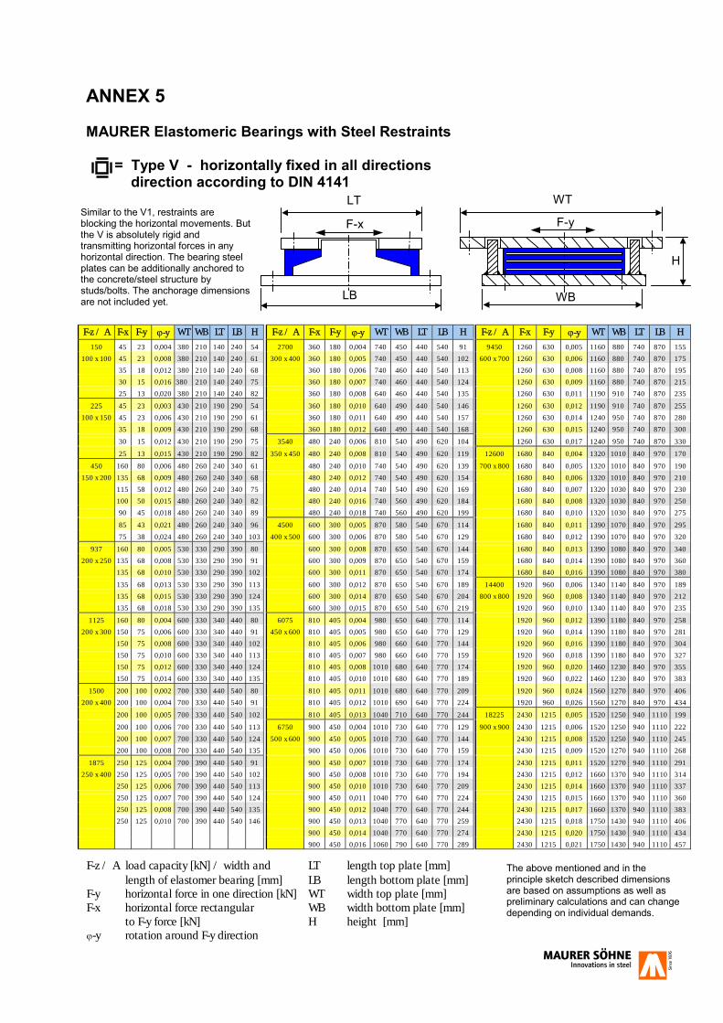
ANNEX 5 MAURER Elastomeric Bearings with Steel Restraints = Type V - horizontally fixed in all directions direction according to DIN 4141
F-z / A F-x F-y �-y WT WB LT LB H F-z / A F-x F-y �-y WT WB LT LB H F-z / A F-x F-y �-y WT WB LT LB H
150 45 23 0,004 380 210 140 240 54 2700 360 180 0,004 740 450 440 540 91 9450 1260 630 0,005 1160 880 740 870 155
100 x 100 45 23 0,008 380 210 140 240 61 300 x 400 360 180 0,005 740 450 440 540 102 600 x 700 1260 630 0,006 1160 880 740 870 175
35 18 0,012 380 210 140 240 68 360 180 0,006 740 460 440 540 113 1260 630 0,008 1160 880 740 870 195
30 15 0,016 380 210 140 240 75 360 180 0,007 740 460 440 540 124 1260 630 0,009 1160 880 740 870 215
25 13 0,020 380 210 140 240 82 360 180 0,008 640 460 440 540 135 1260 630 0,011 1190 910 740 870 235
225 45 23 0,003 430 210 190 290 54 360 180 0,010 640 490 440 540 146 1260 630 0,012 1190 910 740 870 255
100 x 150 45 23 0,006 430 210 190 290 61 360 180 0,011 640 490 440 540 157 1260 630 0,014 1240 950 740 870 280
35 18 0,009 430 210 190 290 68 360 180 0,012 640 490 440 540 168 1260 630 0,015 1240 950 740 870 300
30 15 0,012 430 210 190 290 75 3540 480 240 0,006 810 540 490 620 104 1260 630 0,017 1240 950 740 870 330
25 13 0,015 430 210 190 290 82 350 x 450 480 240 0,008 810 540 490 620 119 12600 1680 840 0,004 1320 1010 840 970 170
450 160 80 0,006 480 260 240 340 61 480 240 0,010 740 540 490 620 139 700 x 800 1680 840 0,005 1320 1010 840 970 190
150 x 200 135 68 0,009 480 260 240 340 68 480 240 0,012 740 540 490 620 154 1680 840 0,006 1320 1010 840 970 210
115 58 0,012 480 260 240 340 75 480 240 0,014 740 540 490 620 169 1680 840 0,007 1320 1030 840 970 230
100 50 0,015 480 260 240 340 82 480 240 0,016 740 560 490 620 184 1680 840 0,008 1320 1030 840 970 250
90 45 0,018 480 260 240 340 89 480 240 0,018 740 560 490 620 199 1680 840 0,010 1320 1030 840 970 275
85 43 0,021 480 260 240 340 96 4500 600 300 0,005 870 580 540 670 114 1680 840 0,011 1390 1070 840 970 295
75 38 0,024 480 260 240 340 103 400 x 500 600 300 0,006 870 580 540 670 129 1680 840 0,012 1390 1070 840 970 320
937 160 80 0,005 530 330 290 390 80 600 300 0,008 870 650 540 670 144 1680 840 0,013 1390 1080 840 970 340
200 x 250 135 68 0,008 530 330 290 390 91 600 300 0,009 870 650 540 670 159 1680 840 0,014 1390 1080 840 970 360
135 68 0,010 530 330 290 390 102 600 300 0,011 870 650 540 670 174 1680 840 0,016 1390 1080 840 970 380
135 68 0,013 530 330 290 390 113 600 300 0,012 870 650 540 670 189 14400 1920 960 0,006 1340 1140 840 970 189
135 68 0,015 530 330 290 390 124 600 300 0,014 870 650 540 670 204 800 x 800 1920 960 0,008 1340 1140 840 970 212
135 68 0,018 530 330 290 390 135 600 300 0,015 870 650 540 670 219 1920 960 0,010 1340 1140 840 970 235
1125 160 80 0,004 600 330 340 440 80 6075 810 405 0,004 980 650 640 770 114 1920 960 0,012 1390 1180 840 970 258
200 x 300 150 75 0,006 600 330 340 440 91 450 x 600 810 405 0,005 980 650 640 770 129 1920 960 0,014 1390 1180 840 970 281
150 75 0,008 600 330 340 440 102 810 405 0,006 980 660 640 770 144 1920 960 0,016 1390 1180 840 970 304
150 75 0,010 600 330 340 440 113 810 405 0,007 980 660 640 770 159 1920 960 0,018 1390 1180 840 970 327
150 75 0,012 600 330 340 440 124 810 405 0,008 1010 680 640 770 174 1920 960 0,020 1460 1230 840 970 355
150 75 0,014 600 330 340 440 135 810 405 0,010 1010 680 640 770 189 1920 960 0,022 1460 1230 840 970 383
1500 200 100 0,002 700 330 440 540 80 810 405 0,011 1010 680 640 770 209 1920 960 0,024 1560 1270 840 970 406
200 x 400 200 100 0,004 700 330 440 540 91 810 405 0,012 1010 690 640 770 224 1920 960 0,026 1560 1270 840 970 434
200 100 0,005 700 330 440 540 102 810 405 0,013 1040 710 640 770 244 18225 2430 1215 0,005 1520 1250 940 1110 199
200 100 0,006 700 330 440 540 113 6750 900 450 0,004 1010 730 640 770 129 900 x 900 2430 1215 0,006 1520 1250 940 1110 222
200 100 0,007 700 330 440 540 124 500 x 600 900 450 0,005 1010 730 640 770 144 2430 1215 0,008 1520 1250 940 1110 245
200 100 0,008 700 330 440 540 135 900 450 0,006 1010 730 640 770 159 2430 1215 0,009 1520 1270 940 1110 268
1875 250 125 0,004 700 390 440 540 91 900 450 0,007 1010 730 640 770 174 2430 1215 0,011 1520 1270 940 1110 291
250 x 400 250 125 0,005 700 390 440 540 102 900 450 0,008 1010 730 640 770 194 2430 1215 0,012 1660 1370 940 1110 314
250 125 0,006 700 390 440 540 113 900 450 0,010 1010 730 640 770 209 2430 1215 0,014 1660 1370 940 1110 337
250 125 0,007 700 390 440 540 124 900 450 0,011 1040 770 640 770 224 2430 1215 0,015 1660 1370 940 1110 360
250 125 0,008 700 390 440 540 135 900 450 0,012 1040 770 640 770 244 2430 1215 0,017 1660 1370 940 1110 383
250 125 0,010 700 390 440 540 146 900 450 0,013 1040 770 640 770 259 2430 1215 0,018 1750 1430 940 1110 406
900 450 0,014 1040 770 640 770 274 2430 1215 0,020 1750 1430 940 1110 434
900 450 0,016 1060 790 640 770 289 2430 1215 0,021 1750 1430 940 1110 457
F-z / A load capacity [kN] / width and LT length top plate [mm] length of elastomer bearing [mm] LB length bottom plate [mm] F-y horizontal force in one direction [kN] WT width top plate [mm]
F-x horizontal force rectangular WB width bottom plate [mm]
to F-y force [kN] H height [mm]
�-y rotation around F-y direction
LB
F-x
LT
H
WB
WT
F-y Similar to the V1, restraints are blocking the horizontal movements. But the V is absolutely rigid and transmitting horizontal forces in any horizontal direction. The bearing steel plates can be additionally anchored to the concrete/steel structure by studs/bolts. The anchorage dimensions are not included yet.
The above mentioned and in the principle sketch described dimensions are based on assumptions as well as preliminary calculations and can change depending on individual demands.

Annex 6 MAURER Seismic Isolators Due to new design strategies that tend to mitigate the effects of earthquakes instead of resisting the same by massive structural strengthening, elastomeric devices have found an important new field of application. Seismic mitigation basically consists in minimizing the amount of mechanical energy that an earthquake imparts to a structure. This is achieved by applying the important instruments of energy dissipation and base isolation. The most effective devices to dissipate energy are viscous dampers (see also catalogue „MAURER Seismic Protection Systems“), whilst elastomeric pads, which in this functional application are referred to as Seismic Isolators, guarantee base isolation. Besides transmitting vertical loads and rotations, the Seismic Isolator also grants horizontal flexibility and re-centring capability - both achieved through shear deformation. In order to fulfil the high performance requirement for Seismic Isolators, MAURER has perfected a special manufacturing technique that satisfies the requirements of prime seismic norms such as the CEN-EUROCODE 8 or AASHTO. The elastomeric bearings of MAURER seismic isolators correspond to the European Norm EN 1337-3 regarding layer structure and material. For seismic demands natural rubber is used for manufacture in order to exploit the elevated mechanical characteristics of said elastomer as well as its additional energy dissipation capability. To improve resistance to atmospheric influences such as ozone and UV rays, the body of the Seismic Isolator is protected by a poly-chloroprene cover layer (see sketch of type V2S). There are two main types of MAURER seismic isolators. The type V2S is fixed, deforming horizontally in all directions. The VE2S is additionally sliding in longitudinal direction to accommodate thermal excursions of the structure, but deforming in the other direction. MAURER technical personnel place their many years of experience in the most suitable conception and design of the individual Seismic Isolation System at the disposal of design engineers as well as the execution of step-by-step non-linear structural analysis.
Type V2S: Isolating seismic elastomeric bearing with anchor plates and cast in concrete anchors
Viaduct Locica/Slovenia where types V2S and VE2S are installed for seismic application, means seismic isolation
Type VE2S: Isolating seismic elastomeric bearing uni-directional sliding and unidirectional deforming in the other direction
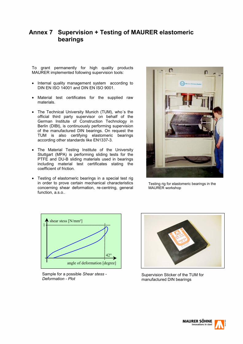
Annex 7 Supervision + Testing of MAURER elastomeric bearings
To grant permanently for high quality products MAURER implemented following supervision tools:
�� Internal quality management system according to
DIN EN ISO 14001 and DIN EN ISO 9001. �� Material test certificates for the supplied raw
materials. �� The Technical University Munich (TUM), who´s the
official third party supervisor on behalf of the German Institute of Construction Technology in Berlin (DIBt), is continuously performing supervision of the manufactured DIN bearings. On request the TUM is also certifying elastomeric bearings according other standards like EN1337-3.
�� The Material Testing Institute of the University
Stuttgart (MPA) is performing sliding tests for the PTFE and DU-B sliding materials used in bearings including material test certificates stating the coefficient of friction.
�� Testing of elastomeric bearings in a special test rig
in order to prove certain mechanical characteristics concerning shear deformation, re-centring, general function, a.s.o..
angle of deformation [degree]
shear stess [N/mm²]
42°
1
Supervision Sticker of the TUM for manufactured DIN bearings
Testing rig for elastomeric bearings in the MAURER workshop
Sample for a possible Shear stess - Deformation - Plot
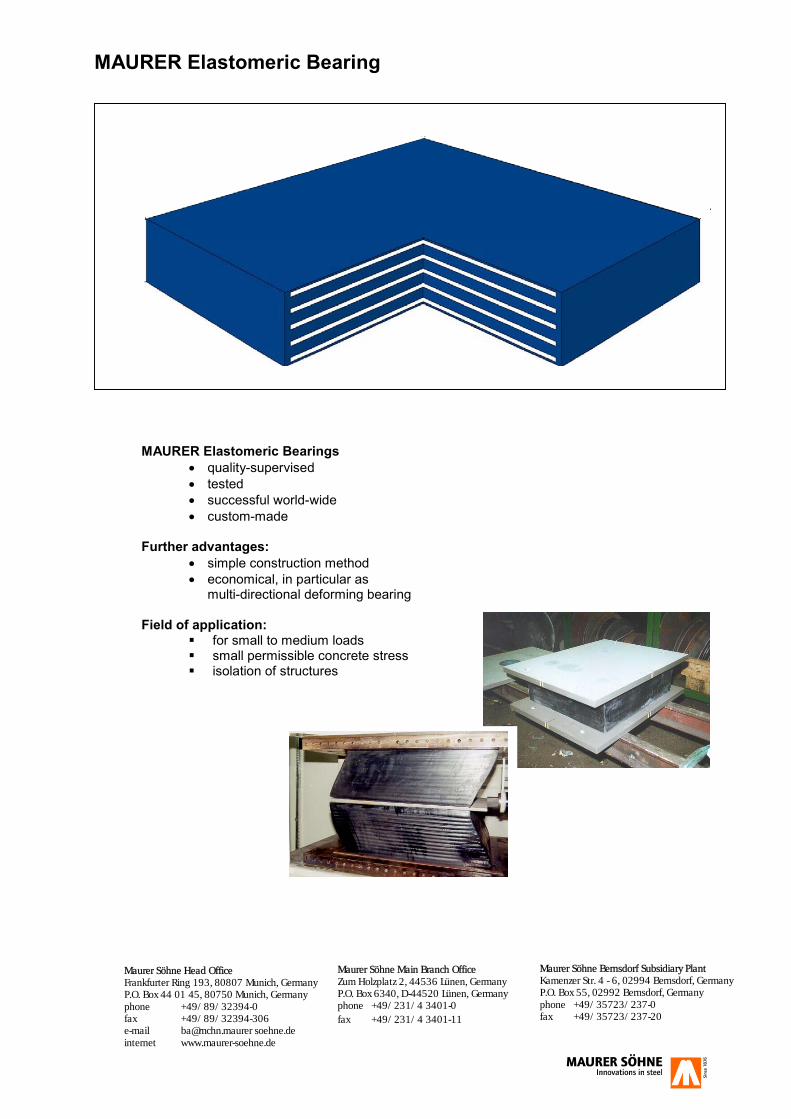
MAURER Elastomeric Bearing
MAURER Elastomeric Bearings
�� quality-supervised �� tested �� successful world-wide �� custom-made
Further advantages: �� simple construction method �� economical, in particular as
multi-directional deforming bearing
Field of application: �� for small to medium loads �� small permissible concrete stress �� isolation of structures
Maurer Söhne Bernsdorf Subsidiary Plant Kamenzer Str. 4 - 6, 02994 Bernsdorf, Germany P.O. Box 55, 02992 Bernsdorf, Germany phone +49/35723/237-0 fax +49/35723/237-20
Maurer Söhne Main Branch Office Zum Holzplatz 2, 44536 Lünen, Germany P.O. Box 6340, D-44520 Lünen, Germany phone +49/231/4 3401-0 fax +49/231/4 3401-11
Maurer Söhne Head OfficeFrankfurter Ring 193, 80807 Munich, Germany P.O. Box 44 01 45, 80750 Munich, Germany phone +49/89/32394-0 fax +49/89/32394-306 e-mail [email protected] soehne.de internet www.maurer-soehne.de