Embed Size (px)
Citation preview
Martian Weather Station Network
Team Odin
Anthony Scott, Nathan McNeal, and Kent LarsonColorado School of Mines
Golden, Colorado80401
Abstract
Martian weather patterns are even less understood then the often-unpredictable weather on earth. In 2002, EPICS 151 teams at the Colorado School of Mines designed modules for a Martian Weather Station Network. The design by team Ares was selected to represent the Colorado School of Mines at the RASC-AL forum a NASA sponsored conference in Florida . In the fall semester of 2004, Team Odin was tasked to evaluate the Team Ares design and to create prototype weather station network to operate in the surface of Mars capable of gathering meteorological data and relaying it back to Earth. The purpose of this weather station network is to gain a deeper understanding of the Martian climate and insight into its weather patterns. The weather station will be durable enough to survive an orbital drop from a passing satellite at an altitude of no less then 1,000 ft, cost less than $10,000, and collect sensor data every minute. It will be able to measure meteorological data such as temperature, pressure, wind speed, wind direction, particle concentration and solar radiation. The weather station will then store the data, send it to a communications module, and then the communications module will relay the data to Earth. All instrumentation will be space qualified, or protected by space-qualified materials to prevent damage to the instrumentation from solar radiation
Introduction:
Martian weather patterns are even less understood then the often-unpredictable weather on earth. In 2002, EPICS 151 teams at the Colorado School of Mines designed modules for a Martian Weather Station Network. The design by team Ares was selected to represent the Colorado School of Mines at the RASC-AL forum a NASA sponsored conference in Florida . In the fall semester of 2004, Team Odin was tasked to evaluate the Team Ares design and to create prototype weather station network to operate in the surface of Mars capable of gathering meteorological data and relaying it back to Earth. The purpose of this weather station network is to gain a deeper understanding of the Martian climate and insight into its weather patterns. The weather station will be durable enough to survive an orbital drop from a passing satellite at an altitude of no less then 1,000 ft, cost less than $10,000, and collect sensor data every minute. It will be able to measure meteorological data such as temperature, pressure, wind speed, wind direction, particle concentration and solar radiation. The weather station will then store the data, send it to a communications module, and then the communications module will relay the data to Earth. All instrumentation will be space qualified, or protected by space-qualified materials to prevent damage to the instrumentation from solar radiation.
The project consists of four subsystems:
Structure and Warm Box Sensors Communications and Information Processing Power
The structure and warm box will protect the electronics from the harshness of the Martian atmosphere which has temperatures ranging from -143°C at the Polar Regions up to 27°C near the Martian equator [1]. The sensors will collect atmospheric data and the communications and information-processing unit will store the data and then transmit the data to Earth. The power to run all of the electronics will come from solar cells on the outside of the structure. Before beginning our research for the modules, operating conditions for the modules had to be determined.
Structure and Warm Box:
Team Ares designed the original structure proposed for the modules in 2002. Their structure has several flaws stemming from the fact that it was designed on a “best case scenario.” The team believes that for their structure to function correctly, a perfect sequence of events from liftoff to touchdown will have to be achieved. Team Ares uses a sectioned shell design that has and axial cylinder for rotation, which “pops” open upon impact [2]. This design is difficult to keep heated as instruments are in different octants. A structure with a single heated section would be more efficient because all of the electronics and the battery together consume one cubic foot of space. The warm box protects the weather station’s heat sensitive instrumentation and electronics from the extreme weather of Mars. Elements of the module that will be stored inside of the warm
box are the battery, brainstems, and radio modems. A heating element made by Elmwood Sensors and powered by the battery will keep the warm box at a constant temperature, which will allow the weather station to gather and store data with accuracy and efficiency.
Technical specifications of Warm Box
Fiberglass will be the main component of the outside and inside or our warm box. Advantages of fiberglass include its availability, low weight, workability, and low cost. If sealed correctly with 3M’s SMC/Fiberglass Panel Adhesive, aerospace qualified fiberglass provides good thermal and radiation insulation. Overall, the warm box will consist of three layers of insulation: a fiberglass outer layer, Aerogel inner layer, and another fiberglass inn layer. The warm box will be one cubic foot. JPL utilized an Aerogel in the Martian Pathfinder. Aerogel is comprised of 99.8% air and provides 39 times more insulation than the best fiberglass insulation. Aerogel has a coefficient of heat transfer of 0.08 W/m*K [4] and Aerogel insulation costs $1.00 per cubic centimeter [3].
Technical Specifications of Heating Element
The warm box will be insulated and contain the battery and electronics. The heating element will be a molded-to-shape design, which will encompass the key elements of the warm box [5]. The team is still in the process of determining the complete specifications for the heater. Elmwood Sensors has provided two equations to determine the power consumption of the heaters inside the warm box [5]. The first equation will calculate the initial power output it will take to raise the temperature of the warm box from the ambient temperature to an operating temperature of 0°C. The second equation calculates the power it will take to maintain an operating temperature of 0°C within the warm box [5]. The exact details of the heater will be known after the determination of values for
Surface Area of Insulation Temperature Difference Aerogel Insulation Availability
The team’s initial estimate of power consumption in 6.62 W to keep the weather station at 0°C in NASA’s Aerogel insulation is used (Appendix A). The heating element will be controlled by a thermistor monitoring the temperature inside the warm box and insulation.
Sensors:
Temperature
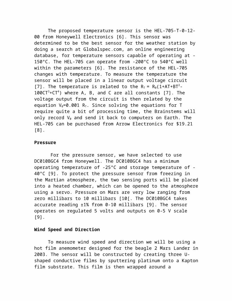
The proposed temperature sensor is the HEL-705-T-0-12-00 from Honeywell Electronics [6]. This sensor was determined to be the best sensor for the weather station by doing a search at Globalspec.com, an online engineering database, for temperature
sensors capable of operating at -150°C. The HEL-705 can operate from -200°C to 540°C well within the parameters [6]. The resistance of the HEL-705 changes with temperature. To measure the temperature the sensor will be placed in a linear output voltage circuit [7]. The temperature is related to the RT = R0(1+AT+BT2-100CT3+CT4) where A, B, and C are all constants [7]. The voltage output from the circuit is then related by the equation V0=0.001 RT. Since solving the equations for T require quite a bit of processing time, the Brainstems will only record V0 and send it back to computers on Earth. The HEL-705 can be purchased from Arrow Electronics for $19.21 [8].
Pressure
For the pressure sensor, we have selected to use DC010BGC4 from Honeywell. The DC010BGC4 has a minimum operating temperature of -25°C and storage temperature of -40°C [9]. To protect the pressure sensor from freezing in the Martian atmosphere, the two sensing ports will be placed into a heated chamber, which can be opened to the atmosphere using a servo. Pressure on Mars are very low ranging from zero millibars to 10 millibars [10[. The DC010BGC4 takes accurate reading ±1% from 0-10 millibars [9]. The sensor operates on regulated 5 volts and outputs on 0-5 V scale [9].
Wind Speed and Direction
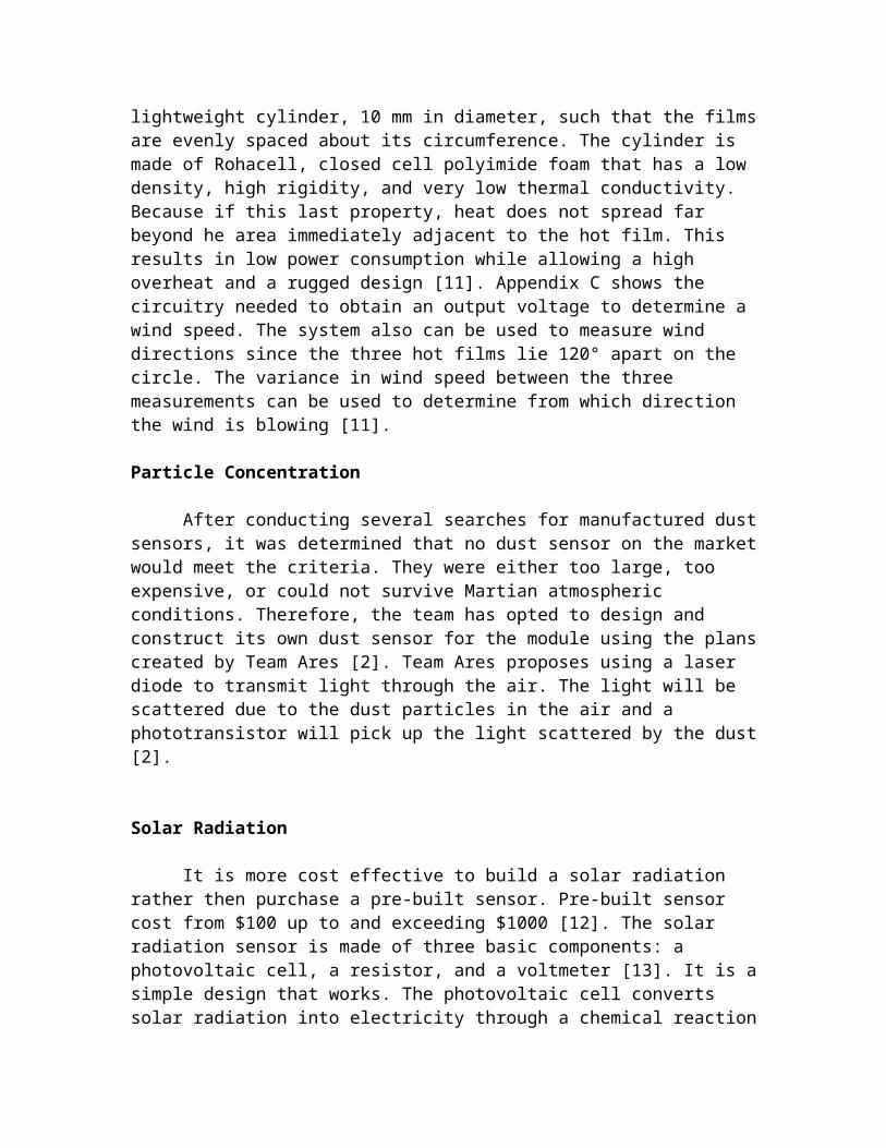
To measure wind speed and direction we will be using a hot film anemometer designed for the beagle 2 Mars Lander in 2003. The sensor will be constructed by creating three U-shaped conductive films by sputtering platinum onto a Kapton film substrate. This film is then wrapped around a lightweight cylinder, 10 mm in diameter, such that the films are evenly spaced about its circumference. The cylinder is made of Rohacell, closed cell polyimide foam that has a low density, high rigidity, and very low thermal conductivity. Because if this last property, heat does not spread far beyond he area immediately adjacent to the hot film. This results in low power consumption while allowing a high overheat and a rugged design [11]. Appendix C shows the circuitry needed to obtain an output voltage to determine a wind speed. The system also can be used to measure wind directions since the three hot films lie 120° apart on the circle. The variance in wind speed between the three measurements can be used to determine from which direction the wind is blowing [11].
Particle Concentration
After conducting several searches for manufactured dust sensors, it was determined that no dust sensor on the market would meet the criteria. They were either too large, too expensive, or could not survive Martian atmospheric conditions. Therefore, the team has opted to design and construct its own dust sensor for the module using the plans created by Team Ares [2]. Team Ares proposes using a laser diode to transmit light through the air. The light will be scattered due to the dust particles in the air and a phototransistor will pick up the light scattered by the dust [2].
Solar Radiation
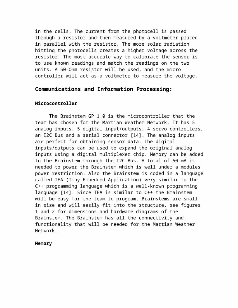
It is more cost effective to build a solar radiation rather then purchase a pre-built sensor. Pre-built sensor cost from $100 up to and exceeding $1000 [12]. The solar radiation sensor is made of three basic components: a photovoltaic cell, a resistor, and a voltmeter [13]. It is a simple design that works. The photovoltaic cell converts solar radiation into electricity through a chemical reaction in the cells. The current from the photocell is passed through a resistor and then measured by a voltmeter placed in parallel with the resistor. The more solar radiation hitting the photocells creates a higher voltage across the resistor. The most accurate way to calibrate the sensor is to use known readings and match the readings on the two units. A 50-Ohm resistor will be used, and the micro controller will act as a voltmeter to measure the voltage.
Communications and Information Processing:
Microcontroller
The Brainstem GP 1.0 is the microcontroller that the team has chosen for the Martian Weather Network. It has 5 analog inputs, 5 digital input/outputs, 4 servo controllers, an I2C Bus and a serial connector [14]. The analog inputs are perfect for obtaining sensor data. The digital inputs/outputs can be used to expand the original analog inputs using a digital multiplexer chip. Memory can be added to the Brainstem through the I2C Bus. A total of 60 mA is needed to power the Brainstem which is well under a modules power restriction. Also the Brainstem is coded in a language called TEA (Tiny Embedded Application) very similar to the C++ programming language which is a well-known programming language [14]. Since TEA is similar to C++ the Brainstem will be easy for the team to program. Brainstems are small in size and will easily fit into the structure, see figures 1 and 2 for dimensions and hardware diagrams of the Brainstem. The Brainstem has all the connectivity and functionality that will be needed for the Martian Weather Network.
Memory
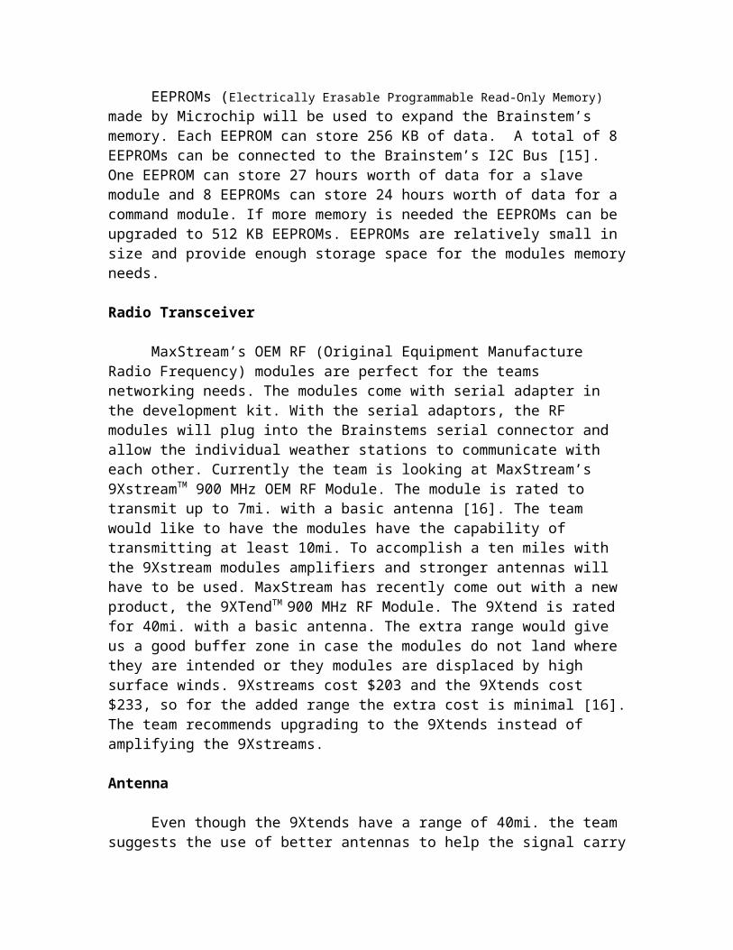
EEPROMs (Electrically Erasable Programmable Read-Only Memory) made by Microchip will be used to expand the Brainstem’s memory. Each EEPROM can store 256 KB of data. A total of 8 EEPROMs can be connected to the Brainstem’s I2C Bus [15]. One EEPROM can store 27 hours worth of data for a slave module and 8 EEPROMs can store 24 hours worth of data for a command module. If more memory is needed the EEPROMs can be upgraded to 512 KB EEPROMs. EEPROMs are relatively small in size and provide enough storage space for the modules memory needs.
Radio Transceiver
MaxStream’s OEM RF (Original Equipment Manufacture Radio Frequency) modules are perfect for the teams networking needs. The modules come with serial adapter in the development kit. With the serial adaptors, the RF modules will plug into
the Brainstems serial connector and allow the individual weather stations to communicate with each other. Currently the team is looking at MaxStream’s 9XstreamTM 900 MHz OEM RF Module. The module is rated to transmit up to 7mi. with a basic antenna [16]. The team would like to have the modules have the capability of transmitting at least 10mi. To accomplish a ten miles with the 9Xstream modules amplifiers and stronger antennas will have to be used. MaxStream has recently come out with a new product, the 9XTendTM 900 MHz RF Module. The 9Xtend is rated for 40mi. with a basic antenna. The extra range would give us a good buffer zone in case the modules do not land where they are intended or they modules are displaced by high surface winds. 9Xstreams cost $203 and the 9Xtends cost $233, so for the added range the extra cost is minimal [16]. The team recommends upgrading to the 9Xtends instead of amplifying the 9Xstreams.
Antenna
Even though the 9Xtends have a range of 40mi. the team suggests the use of better antennas to help the signal carry in the right direction. MaxStream’s 25-inch Fiberglass Base Station Antenna (Part Number: A09-F5NF-M at $174) is recommended for module-to-module communication. MaxStream’s 25-inch Yagi 6 element antenna (Part Number: A09-Y11NF at $70) is recommended for module-to-satellite communication [16]. The added directionality of a modules signal will increase the stability of the weather station network.
Meeting Requirements
The Networking and Control subsystem will ensure that the weather station network meets the requirements of being able to collect climatic data, being able to transmit data to a satellite and being able to provide data from 100 mi2, to uplink to a satellite. The Martian weather network will meet all of these requirements.
Assembly and Operation
The Brainstem will be the main unit in a weather station. Memory is connected through the I2C Bus of the Brainstem. The RF modules are connected to the serial connection of the Brainstem and the antenna is connected to the RF module. The sensors can be connected through the analog or digital pins. Power will be connected through the power inputs on both the Brainstem and RF modules. Finally, the structure and heating will encompass the electronics keeping them safe from the harsh Martian environment.
The Brainstem is the heart of every module. It makes the network possible. Through the use of four programs running simultaneously on each weather station a network of stations is created. The most efficient design for the layout of the network can be seen [GP18]. Three command modules will be used to keep the network running even if one or two command modules should fail. Only one command module will be active, as command and the other two will act, as slaves until the command module fails and then one of the other modules will be activated to run the network. Each module will take sensor data every minute and a time stamp will be issued to each reading to keep the
readings in order. Every four hours the command module will contact the individual slave modules and gather their sensor data. If the RF modules are working at 20% efficiency and assuming the satellite passes every 12 hours, it will take 9 minutes for a command module to send all of its senor data to the satellite. When the sensor data is passed to the satellite, it will then be sent back to earth and the sensor data will then be translate into climatic data. These are just the basics how the Martian weather network will operate. As the code is perfected, the operation of the network can be listed in greater detail.
Power:
Solar Panel Technical Specifications
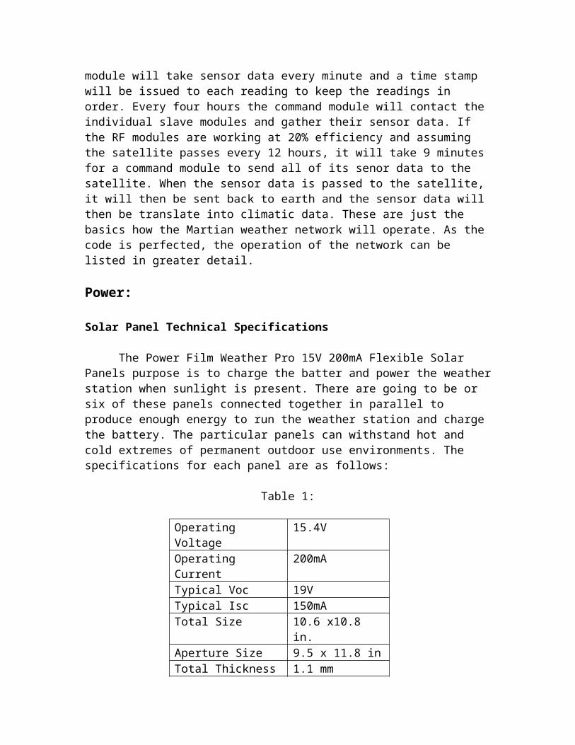
The Power Film Weather Pro 15V 200mA Flexible Solar Panels purpose is to charge the batter and power the weather station when sunlight is present. There are going to be or six of these panels connected together in parallel to produce enough energy to run the weather station and charge the battery. The particular panels can withstand hot and cold extremes of permanent outdoor use environments. The specifications for each panel are as follows:
Table 1:
Operating Voltage 15.4VOperating Current 200mATypical Voc 19VTypical Isc 150mATotal Size 10.6 x10.8 in.Aperture Size 9.5 x 11.8 inTotal Thickness 1.1 mmWeight 94.5 g (3.3 oz)
We plan to use five or six of panel connected in parallel to give us an operating current of 1A. Connecting the panels in series would have give us additional voltage, but however, we do not need the additional voltage as the operating voltage of our battery is 12V/ We chose the Power Film because of it durability and ease of storage while in flight. It is UV-stabilized surface, which ensures the panel’s safety from solar radiation. It also has an extra edge seal to protect the solar panel from weather extremes. Last of all, it has tin-coated connectors to ensure a quality connection [17].
The cost of each individual solar panel is $94.95 from dealer Sundance Solar, who is based in New Hampshire. The manufacture of the solar panel is Iowa Thin Films Company [17].
Battery Technical Specifications
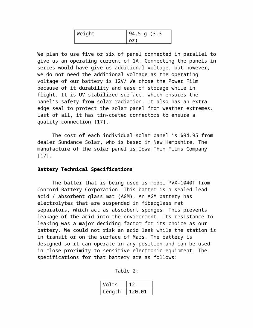
The batter that is being used is model PVX-1040T from Concord Battery Corporation. This batter is a sealed lead acid / absorbent glass mat (AGM). An AGM
battery has electrolytes that are suspended in fiberglass mat separators, which act as absorbent sponges. This prevents leakage of the acid into the environment. Its resistance to leaking was a major deciding factor for its choice as our battery. We could not risk an acid leak while the station is in transit or on the surface of Mars. The battery is designed so it can operate in any position and can be used in close proximity to sensitive electronic equipment. The specifications for that battery are as follows:
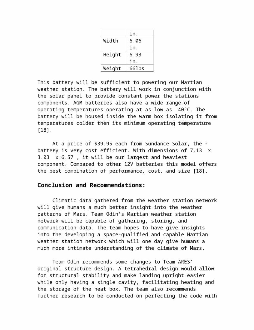
Table 2:
Volts 12Length 120.01 in.Width 6.06 in.Height 6.93 in.Weight 66lbs
This battery will be sufficient to powering our Martian weather station. The battery will work in conjunction with the solar panel to provide constant power the stations components. AGM batteries also have a wide range of operating temperatures operating at as low as -40ºC. The battery will be housed inside the warm box isolating it from temperatures colder then its minimum operating temperature [18].
At a price of $39.95 each from Sundance Solar, the battery is very cost efficient. With dimensions of 7.13” x 3.03” x 6.57”, it will be our largest and heaviest component. Compared to other 12V batteries this model offers the best combination of performance, cost, and size [18].
Conclusion and Recommendations:
Climatic data gathered from the weather station network will give humans a much better insight into the weather patterns of Mars. Team Odin’s Martian weather station network will be capable of gathering, storing, and communication data. The team hopes to have give insights into the developing a space-qualified and capable Martian weather station network which will one day give humans a much more intimate understanding of the climate of Mars.
Team Odin recommends some changes to Team ARES’ original structure design. A tetrahedral design would allow for structural stability and make landing upright easier while only having a single cavity, facilitating heating and the storage of the heat box. The team also recommends further research to be conducted on perfecting the code with the weather stations programs. Gallium Arsenide solar panels, which NASA uses on its satellites, would provide better performance than the silicon panels, which the team has selected. They are currently commercially unavailable or extremely difficult to find. In the sensing subsystem, the particle concentration sensor needs further research to design the most efficient and accurate means to measuring particle concentration in the atmosphere.
Team Odin has recently started the discussion with several groups on the implementation of prototypes across the state of Colorado to begin field-testing of the modules. The Compass Montessori Middle School in Jefferson County Colorado has recently contacted our advisor Dr. Robert Knecht on monitoring weather patterns across the schools 5-acre farm. The school should provide valuable information for initial testing and its close proximity to the Colorado School of Mines allows for quick fixes and upgrades should problems arise in the network. Future plans for testing in Colorado include placements of small testing networks in some of Colorado’s most extreme environments such as the Great Sand Dunes national park to monitor dust concentration and another possible location being trail ridge road in the Rocky Mountain national park which has some of the coldest temperatures ever recorded in Colorado
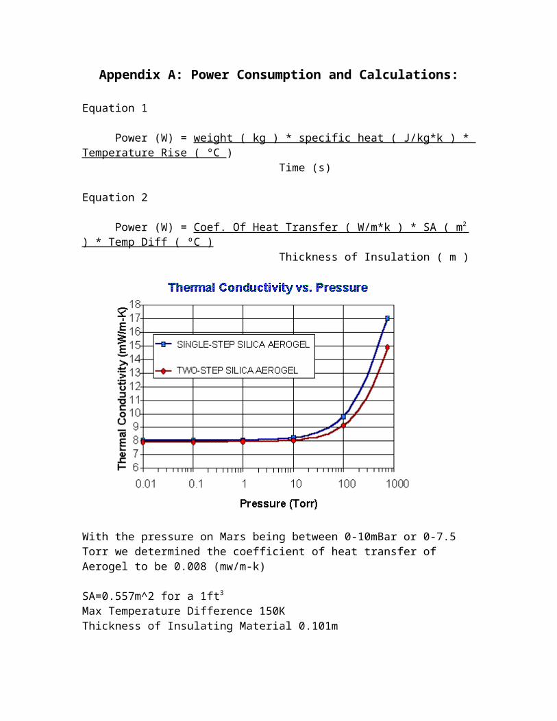
Appendix A: Power Consumption and Calculations:
Equation 1
Power (W) = weight ( kg ) * specific heat ( J/kg*k ) * Temperature Rise ( ºC )Time (s)
Equation 2
Power (W) = Coef. Of Heat Transfer ( W/m*k ) * SA ( m 2 ) * Temp Diff ( ºC ) Thickness of Insulation ( m )
With the pressure on Mars being between 0-10mBar or 0-7.5 Torr we determined the coefficient of heat transfer of Aerogel to be 0.008 (mw/m-k)
SA=0.557m^2 for a 1ft3
Max Temperature Difference 150KThickness of Insulating Material 0.101m
Power Consumption is then 6.62 W
Elmwood Sensors, “Flexible Heater Solutions,” Invensys Sensor Control
Accessed 11/07/2004, posted 2004
http://eande.lbl.gov/ECS/aerogels/satcond.htm
Appendix B: Temperature Equation Coefficients
http://content.honeywell.com/sensing/prodinfo/temperature/catalog/c15_85.pdf
Appendix C: Hot Film Anemometer Circuitry
http://www.atm.ox.ac.uk/user/wilson/B2WS/

Reference:
[1] Mars: Temperature Overview, James E. Tillman. <http://www-k12.atmos.washington.edu/k12/resources/mars_data-information/temperature_overview.html. accessed November 8>, 2004.
[2] Team ARES, “Martian Weather Station,” Colorado School of Mines, Accessed 11/07/2004, posted January 13, 2004.
[3] “Aerogel Capabilities.” http://stardust.jpl.nasa.gov/tech/aerogel.html. Accessed 11/07/2004, posted January 13, 2004.
[4] M. Ayers, “Thermal Properties of Silica Aerogels,” Ernest Orlando Lawrence, <http://eande.lbl.gov/ECS/aerogels/satoc.htm. accessed 11/07/2004>, posted 2004.
[5] Elmwood sensors, “Flexible Heater Solutions.” Invensys Sensor Control, <http://content.honeywell.com/sensing/prodinfo/heaters/customflexibleheaters.asp. accessed 11/07/2004>, posted 2004.
[6] Temperature Sensors, Honeywell, http://content.honeywell.com/sensing/prodinfo/temperature/. Accessed November 8, 2004.
[7] Temperature Sensors: Product Guide and Technical Specifications http://content.honeywell.com/sensing/prodinfo/temperature/catalog/c15_85.pdf . Accessed November 8, 2004.
[8] Arrow Electronics www.arrow.com. Accessed November 8, 2004.
[9] Pressure Sensors: Product Guide and Technical Specifications for DC010BGC4&F, http://content.sensing.honeywell.com/datasheet.asp?PN=DC010FBGC4&FAM=Pressure&P=10824,3329 . Accessed November 8, 2004.
[10] Weather Reports from Mars. http://mars.jpl.nasa.gov/MPF/science/weather.html . Accessed November 8 , 2004.
[11] The Beagle 2 Lander: Wind Sensor, C.F. Wilson and S.B. Calcutt http://www.atm.ox.ac.uk/user/wilson/B2WS/. Accessed November 8, 2004.
[12] Daystar Inc., <http://www.zianet.com/daystar./solar_meters.html. Accessed April 19>, 2004.
[13] Measuring Solar radiation, Chuck Wright. <http://chuck-wright.com/projects/pvmeasure.html. Accessed April 19>, 2004.
[14] Brainstem Documentation. <http://www.acroname.com/brainstem/ref/ref.html. accessed November 8>, 2004.
[15] 256K I2C CMOS Serial EEPROM. <http://ww1.microchip.com/downloads/en/DeviceDoc/21203M.pdf. accessed November 8>, 2004.
[16] MaxStream. http://www.maxstream.net/. accessed November 8 , 2004.
[17] “PT15-300,” PowerFilm. <http://www.iowathinfilm.com/products/powerfilm/modspecs/PT15300.htm. Accessed November 1>, 2004.
[18] “Sun-Extender® Battery Design Features,” Concord. <http://www.concordebattery.com/products/psb_eleclspeifications.cfm. accessed November 1>, 2004.