Embed Size (px)
Citation preview
A
lfordslcs©
K
1
htiCiapgttftRsi
0d
Available online at www.sciencedirect.com
Wear 264 (2008) 679–684
Wear behavior in turning high hardness alloy steel by CBN tool
H.M. Lin a, Y.S. Liao b,∗, C.C. Wei b
a Department of Mechanical Engineering, Nan Kai Institute of Technology, Nantou 542, Taiwanb Department of Mechanical Engineering, National Taiwan University, Taipei 106, Taiwan
Received 13 March 2006; received in revised form 10 April 2007; accepted 6 June 2007Available online 19 July 2007
bstract
Tool wear mechanisms in turning of high hardness alloy steels by CBN tools under various speeds are investigated by experimental studies. Inow speed cutting, the binder of the hard particles of the cutting tool is found to be removed from the substrate due to a high cutting force, resultingrom low cutting temperature, and abrasion dominates tool wear. When the cutting speed is increased, a protective layer resulting from the diffusionf the bond material of the cutting tool starts to form on the chip-tool interface. This layer works as a diffusion barrier. Hence, tool wear rate iseduced and the usable life of the CBN tool is prolonged. However, when the cutting speed is further increased, cutting temperature becomes theominant factor instead of the cutting force. The high cutting speed causes inhomogeneous shear strain, and a transition from continuous chip toaw-tooth chip occurs. The friction force is found to increase because of the very irregular chip-tool contact. This would remove the protective
ayer. In addition, the bond between tool particles is weakened due to serious diffusion between the work material and the cutting tool under highutting temperature. Subsequently, hard particles are detached, and tool life is reduced. Hence, it is concluded that there exists an optimal cuttingpeed of CBN tool in turning of high hardness alloy steels.2007 Elsevier B.V. All rights reserved.
BtaotfoiriHia
2
eywords: CBN; Tool life; Tool wear mechanism; High hardness alloy steel
. Introduction
CBN tool material has been applied widely in the cutting ofardened steels, tool steels, difficult-to-cut materials, etc. dueo its high temperature stability, hot hardness and low affin-ty to iron. In cutting hardened steels of different hardness byBN tool, it was found that tool wear reduced first with the
ncrease of the hardness of work material until a hardness ofbout HRc 50 where the wear started to increase abruptly. Thishenomenon had been studied and unveiled by several investi-ators [1–4]. In cutting hardened steels, it was also noted thathe life of CBN tools showed an increasing and then decreasingrend with increasing cutting speed [5–7]. This is quite differentrom that described by the traditional Taylor’s tool life equa-ion where tool life is inversely proportional to cutting speed.
egarding CBN tool wear mechanism, Zimmermann et al. [8]howed that wear of the tool in the crater region was primar-ly tribochemical, and most likely chemical in the flank region.
∗ Corresponding author. Tel.: +886 2 2362 6431; fax: +886 2 2363 1755.E-mail address: [email protected] (Y.S. Liao).
tnbT−
043-1648/$ – see front matter © 2007 Elsevier B.V. All rights reserved.oi:10.1016/j.wear.2007.06.006
arry and ByrneT also suggested that the chemical wear washe dominant mechanism of CBN tools [9]. The works by Chound Evans [10] and Poulachon et al. [11] indicated that the Tsizef carbide particles of the workpiece had significant effects onool wear. TChou et al. noted that there was a transferred layerormed on the flank wear land, and it would lead to adhesive wearf the cutting tool [12]. All these studies provide more insightnto CBN tool wear in cutting hardened steels. Nevertheless, theeal mechanism governing the aforementioned peculiar increas-ng then decreasing tool life characteristic has not been clarified.ence, the purposes of this paper are to study the cutting behav-
ors and tool wear mechanisms in the turning of high hardnesslloy steels by CBN tools under various cutting speeds.
. Experiments
Experiments were conducted on a lathe. The insert used inhe turning experiments had a land of 0.2 mm width and 20◦
egative rake angle. It contains 50% and 45% of CBN, and TiC-ased binder, respectively, and a small amount of Al (about 5%).he lathe-tool nomenclature denoted by the German system was6, −6, 6, 6, 30, 0, 0.8. Work material was AISI 4340 alloy steel,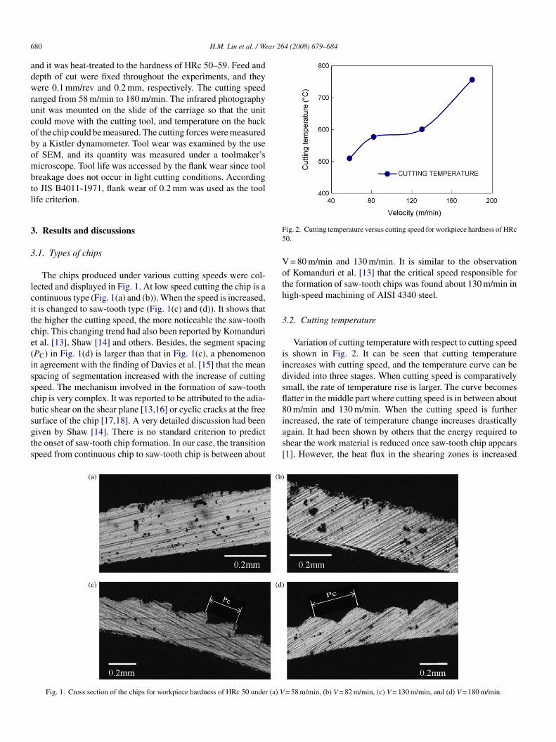
6 ar 264 (2008) 679–684
adwrucobombtl
3
3
lcitce(isscbsgts
F5
Voth
3
iidsfl8
80 H.M. Lin et al. / We
nd it was heat-treated to the hardness of HRc 50–59. Feed andepth of cut were fixed throughout the experiments, and theyere 0.1 mm/rev and 0.2 mm, respectively. The cutting speed
anged from 58 m/min to 180 m/min. The infrared photographynit was mounted on the slide of the carriage so that the unitould move with the cutting tool, and temperature on the backf the chip could be measured. The cutting forces were measuredy a Kistler dynamometer. Tool wear was examined by the usef SEM, and its quantity was measured under a toolmaker’sicroscope. Tool life was accessed by the flank wear since tool
reakage does not occur in light cutting conditions. Accordingo JIS B4011-1971, flank wear of 0.2 mm was used as the toolife criterion.
. Results and discussions
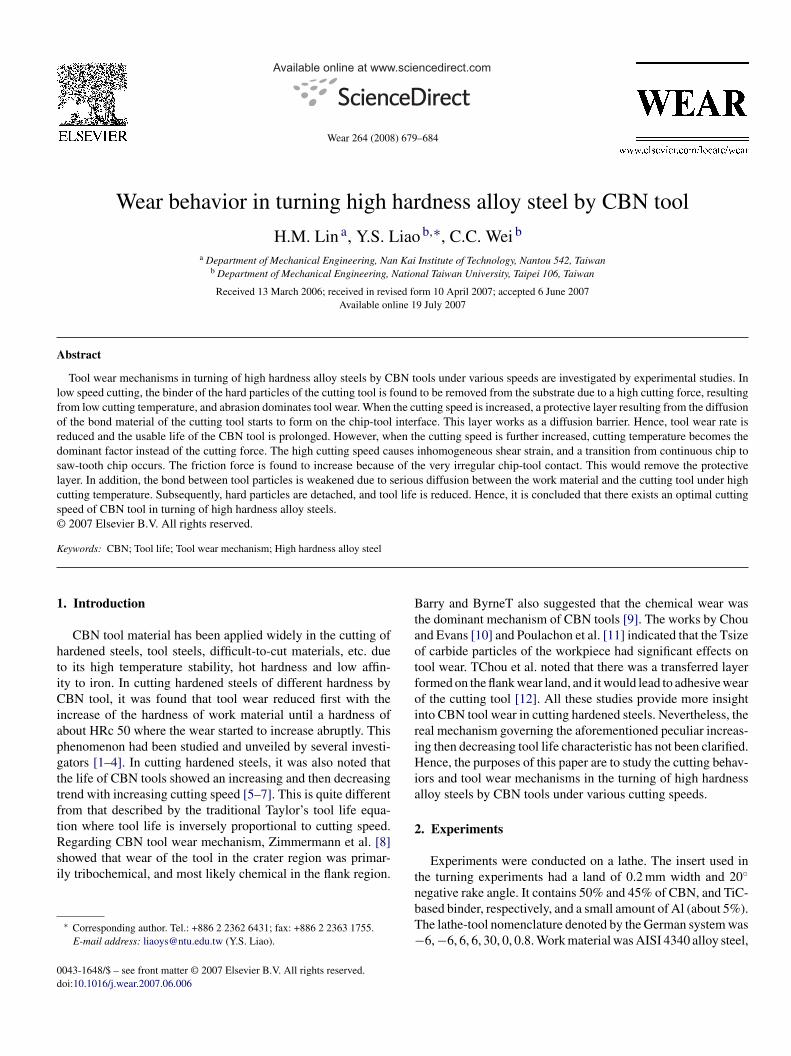
.1. Types of chips
The chips produced under various cutting speeds were col-ected and displayed in Fig. 1. At low speed cutting the chip is aontinuous type (Fig. 1(a) and (b)). When the speed is increased,t is changed to saw-tooth type (Fig. 1(c) and (d)). It shows thathe higher the cutting speed, the more noticeable the saw-toothhip. This changing trend had also been reported by Komandurit al. [13], Shaw [14] and others. Besides, the segment spacingPC) in Fig. 1(d) is larger than that in Fig. 1(c), a phenomenonn agreement with the finding of Davies et al. [15] that the meanpacing of segmentation increased with the increase of cuttingpeed. The mechanism involved in the formation of saw-toothhip is very complex. It was reported to be attributed to the adia-atic shear on the shear plane [13,16] or cyclic cracks at the free
urface of the chip [17,18]. A very detailed discussion had beeniven by Shaw [14]. There is no standard criterion to predicthe onset of saw-tooth chip formation. In our case, the transitionpeed from continuous chip to saw-tooth chip is between aboutias[
Fig. 1. Cross section of the chips for workpiece hardness of HRc 50 under (a) V
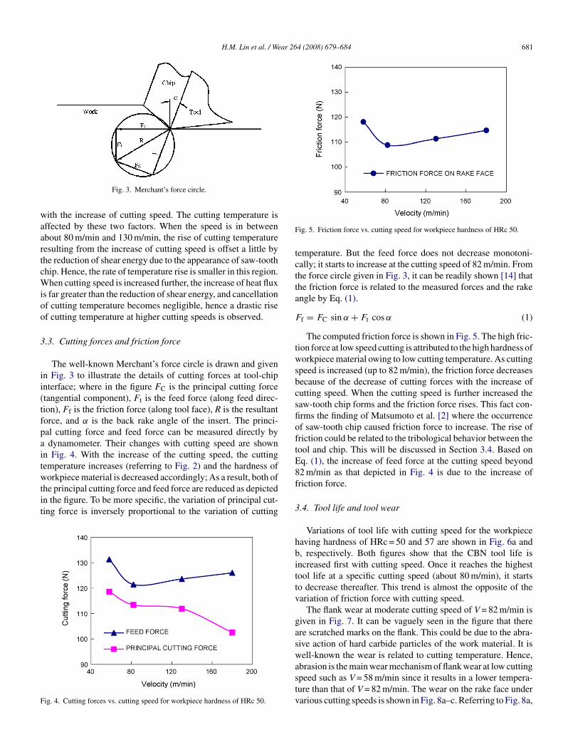
ig. 2. Cutting temperature versus cutting speed for workpiece hardness of HRc0.
= 80 m/min and 130 m/min. It is similar to the observationf Komanduri et al. [13] that the critical speed responsible forhe formation of saw-tooth chips was found about 130 m/min inigh-speed machining of AISI 4340 steel.
.2. Cutting temperature
Variation of cutting temperature with respect to cutting speeds shown in Fig. 2. It can be seen that cutting temperaturencreases with cutting speed, and the temperature curve can beivided into three stages. When cutting speed is comparativelymall, the rate of temperature rise is larger. The curve becomesatter in the middle part where cutting speed is in between about0 m/min and 130 m/min. When the cutting speed is further
ncreased, the rate of temperature change increases drasticallygain. It had been shown by others that the energy required tohear the work material is reduced once saw-tooth chip appears1]. However, the heat flux in the shearing zones is increased= 58 m/min, (b) V = 82 m/min, (c) V = 130 m/min, and (d) V = 180 m/min.
H.M. Lin et al. / Wear 264 (2008) 679–684 681
waartcWioo
3
ii(tfpaitwtit
F
F
tctta
F
twsbcsfioftE8
Fig. 3. Merchant’s force circle.
ith the increase of cutting speed. The cutting temperature isffected by these two factors. When the speed is in betweenbout 80 m/min and 130 m/min, the rise of cutting temperatureesulting from the increase of cutting speed is offset a little byhe reduction of shear energy due to the appearance of saw-toothhip. Hence, the rate of temperature rise is smaller in this region.
hen cutting speed is increased further, the increase of heat fluxs far greater than the reduction of shear energy, and cancellationf cutting temperature becomes negligible, hence a drastic risef cutting temperature at higher cutting speeds is observed.
.3. Cutting forces and friction force
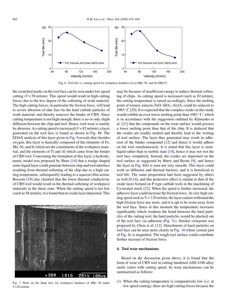
The well-known Merchant’s force circle is drawn and givenn Fig. 3 to illustrate the details of cutting forces at tool-chipnterface; where in the figure FC is the principal cutting forcetangential component), Ft is the feed force (along feed direc-ion), Ff is the friction force (along tool face), R is the resultantorce, and α is the back rake angle of the insert. The princi-al cutting force and feed force can be measured directly bydynamometer. Their changes with cutting speed are shown
n Fig. 4. With the increase of the cutting speed, the cuttingemperature increases (referring to Fig. 2) and the hardness of
orkpiece material is decreased accordingly; As a result, both ofhe principal cutting force and feed force are reduced as depictedn the figure. To be more specific, the variation of principal cut-ing force is inversely proportional to the variation of cutting
ig. 4. Cutting forces vs. cutting speed for workpiece hardness of HRc 50.
f
3
hbittv
gaswastv
ig. 5. Friction force vs. cutting speed for workpiece hardness of HRc 50.
emperature. But the feed force does not decrease monotoni-ally; it starts to increase at the cutting speed of 82 m/min. Fromhe force circle given in Fig. 3, it can be readily shown [14] thathe friction force is related to the measured forces and the rakengle by Eq. (1).
f = FC sin α + Ft cos α (1)
The computed friction force is shown in Fig. 5. The high fric-ion force at low speed cutting is attributed to the high hardness oforkpiece material owing to low cutting temperature. As cutting
peed is increased (up to 82 m/min), the friction force decreasesecause of the decrease of cutting forces with the increase ofutting speed. When the cutting speed is further increased theaw-tooth chip forms and the friction force rises. This fact con-rms the finding of Matsumoto et al. [2] where the occurrencef saw-tooth chip caused friction force to increase. The rise ofriction could be related to the tribological behavior between theool and chip. This will be discussed in Section 3.4. Based onq. (1), the increase of feed force at the cutting speed beyond2 m/min as that depicted in Fig. 4 is due to the increase ofriction force.
.4. Tool life and tool wear
Variations of tool life with cutting speed for the workpieceaving hardness of HRc = 50 and 57 are shown in Fig. 6a and, respectively. Both figures show that the CBN tool life isncreased first with cutting speed. Once it reaches the highestool life at a specific cutting speed (about 80 m/min), it startso decrease thereafter. This trend is almost the opposite of theariation of friction force with cutting speed.
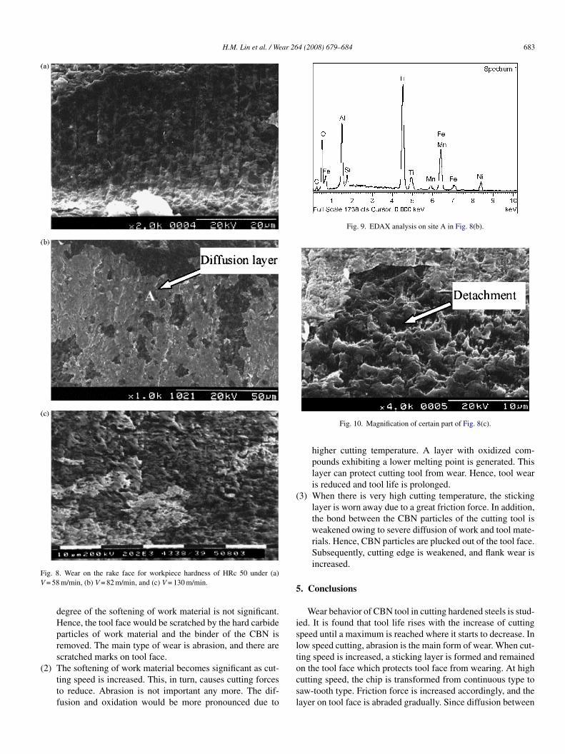
The flank wear at moderate cutting speed of V = 82 m/min isiven in Fig. 7. It can be vaguely seen in the figure that therere scratched marks on the flank. This could be due to the abra-ive action of hard carbide particles of the work material. It isell-known the wear is related to cutting temperature. Hence,
brasion is the main wear mechanism of flank wear at low cuttingpeed such as V = 58 m/min since it results in a lower tempera-ure than that of V = 82 m/min. The wear on the rake face underarious cutting speeds is shown in Fig. 8a–c. Referring to Fig. 8a,
682 H.M. Lin et al. / Wear 264 (2008) 679–684
piece
tcfTtwcdbgEoMronsrtBom(
FV
mitp1wiaatosoltttwta
Fig. 6. Tool life vs. cutting speed for work
he scratched marks on the tool face can be seen under low speedutting (V = 58 m/min). This speed would result in high cuttingorces due to the less degree of the softening of work material.he high cutting forces, in particular the friction force, will lead
o severe abrasion of rake face by the hard carbide particles ofork material; and thereby removes the binder of CBN. Since
utting temperature is not high enough, there is no or only slightiffusion between the chip and tool. Hence, tool wear is mainlyy abrasion. As cutting speed is increased (V = 82 m/min), a layerenerated on the tool face is found as shown in Fig. 8b. TheDAX analysis of this layer given in Fig. 9 reveals that, besidesxygen, this layer is basically composed of the elements of Fe,n, Ni, and Si which are the constituents of the workpiece mate-
ial, and the elements of Ti and Al which came from the binderf CBN tool. Concerning the formation of this layer, a hydrody-amic model was proposed by Shaw [14] that a wedge-shapedemi-liquid layer could generate between chip and tool interfaceesulting from thermal softening of the chip due to a high cut-ing temperature, subsequently leading to a squeeze-film action.ossom [19] also clarified that the lower thermal conductivity
f CBN tool would result in the thermal softening of workpieceaterials in the shear zone. When the cutting speed is too lowsuch as 58 m/min), it is found that no oxide layer deposited. This
ig. 7. Wear on the flank face for workpiece hardness of HRc 50 under= 82 m/min.
oCathtscoptof
4
fss
(
hardness of (a) HRc 50, and (b) HRc57.
ay be because of insufficient energy to induce thermal soften-ng of chips. As cutting speed is increased (such as 82 m/min),he cutting temperature is raised accordingly. Since the meltingoint of ternary eutectic FeO–SiO2–Al2O3 could be reduced to083 ◦C [20]. It is expected that the complex oxides in this studyould exhibit an even lower melting point than 1083 ◦C, which
s in accordance with the suggestion outlined by Klimenko etl. [21] that the compounds on the wear surface would possesslower melting point than that of the chip. It is deduced that
he oxides are readily melted and thereby lead to the wettingf tool surface. The layer thus generated may result in adhe-ion of the binder compound [12] and hence it would adheren the tool simultaneously. It is noted that this layer is semi-iquid rather than in mobile state [14], hence it may not wet theool face completely. Instead, the oxides are deposited on theool surface as suggested by Barry and Byrne [9], and hencehe layer in Fig. 8(b) is seen not very smooth. This layer couldork as diffusion and thermal barriers, and it is beneficial to
ool life. The same proposition had been suggested by otherss well [9,14], and this protective effect is similar to that of thexide layer formed on P-type carbide tools in the machining ofa-treated steels [22]. When the speed is further increased, thedhesive layer could increase the friction force. At very high cut-ing speed such as V = 130 m/min, the layer cannot withstand theigh friction force any more, and it is apt to be worn away fromhe tool face. Since at this moment the temperature increasesignificantly which weakens the bond between the hard parti-les of the cutting tool, the hard particles would be plucked outf the tool face via adhesion (Fig. 7c). Similar viewpoint wasroposed by Chou et al. [12]. Detachment of hard particles onool face can be seen more clearly in Fig. 10 where certain partf Fig. 8c is magnified. The rough tool surface could contributeurther increase of friction force.
. Tool wear mechanisms
Based on the discussion given above, it is found that theorm of wear of CBN tool in cutting hardened AISI 4340 alloyteels varies with cutting speed. Its wear mechanisms can be
ummarized as follows:1) When the cutting temperature is comparatively low (i.e. atlow speed cutting), there are high cutting forces because the
H.M. Lin et al. / Wear 264 (2008) 679–684 683
FV
(
Fig. 9. EDAX analysis on site A in Fig. 8(b).
(
5
islt
ig. 8. Wear on the rake face for workpiece hardness of HRc 50 under (a)= 58 m/min, (b) V = 82 m/min, and (c) V = 130 m/min.
degree of the softening of work material is not significant.Hence, the tool face would be scratched by the hard carbideparticles of work material and the binder of the CBN isremoved. The main type of wear is abrasion, and there arescratched marks on tool face.
2) The softening of work material becomes significant as cut-ting speed is increased. This, in turn, causes cutting forcesto reduce. Abrasion is not important any more. The dif-fusion and oxidation would be more pronounced due to
ocsl
Fig. 10. Magnification of certain part of Fig. 8(c).
higher cutting temperature. A layer with oxidized com-pounds exhibiting a lower melting point is generated. Thislayer can protect cutting tool from wear. Hence, tool wearis reduced and tool life is prolonged.
3) When there is very high cutting temperature, the stickinglayer is worn away due to a great friction force. In addition,the bond between the CBN particles of the cutting tool isweakened owing to severe diffusion of work and tool mate-rials. Hence, CBN particles are plucked out of the tool face.Subsequently, cutting edge is weakened, and flank wear isincreased.
. Conclusions
Wear behavior of CBN tool in cutting hardened steels is stud-ed. It is found that tool life rises with the increase of cuttingpeed until a maximum is reached where it starts to decrease. Inow speed cutting, abrasion is the main form of wear. When cut-ing speed is increased, a sticking layer is formed and remained
n the tool face which protects tool face from wearing. At highutting speed, the chip is transformed from continuous type toaw-tooth type. Friction force is increased accordingly, and theayer on tool face is abraded gradually. Since diffusion between
6 ar 26
wswi
R
[
[
[
[
[[
[
[
[
[
[
84 H.M. Lin et al. / We
ork and tool materials becomes more severe at high cuttingpeed, the bond between the hard particles is weakened, andear on the rake face is increased drastically. Together with the
ncrease of crater wear, flank wear is increased.
eferences
[1] N. Narutaki, Y. Yamane, Tool wear and cutting temperature of CBN toolin machining of hardened steels, Ann. CIRP 28 (1) (1979) 23–28.
[2] Y. Matsumoto, M.M. Barash, C.R. Liu, Cutting mechanism during machin-ing of hardened steel, Mater. Sci. Technol. 3 (1987) 299–305.
[3] T. Ohtani, H. Yokogawa, The effects of workpiece hardness on tool wearcharacteristics, Bull. Jpn. Soc. Prec. Eng. 22 (1988) 229–231.
[4] S.Y. Luo, Y.S. Liao, Y.Y. Tsai, Wear characteristics in turning high hardnessalloy steel by ceramic and CBN tools, J. Mater. Process. Technol. 88 (1999)114–121.
[5] K. Weinert, Relation between process energy and tool wear when turninghardfacing alloys, Ann. CIRP 43 (1) (1994) 97–100.
[6] K. Shintani, H. Kato, T. Maeda, Y. Fujimura, A. Yamamoto, Cutting per-formance of CBN tools in machining of nickel based superalloy, JSPE 58(1992) 1685–1690 (in Japanese).
[7] A.G. Mamalis, J. Kundrak, M. Horvath, Wear and tool life of CBN cuttingtools, Int. J. Adv. Manuf. Technol. 20 (2002) 475–479.
[8] M. Zimmermann, M. Lahres, D.V. Viens, B.L. Laube, Investigations of thewear of cubic boron nitride cutting tools using Auger electron spectroscopyand X-ray analysis by EPMA, Wear 209 (1997) 241–246.
[9] J. Barry, G. Byrne, Cutting tool wear in the machining of hardened steels.Part II. Cubic boron nitride cutting tool wear, Wear 247 (2001) 152–160.
[
[
4 (2008) 679–684
10] Y.K. Chou, C.J. Evans, Tool wear mechanism in continuous cutting ofhardened tool steels, Wear 212 (1997) 59–65.
11] G. Poulachon, B.P. Bandyopadhyay, I.S. Jawahir, S. Pheulpin, E. Seguin,Wear behavior of CBN tools while turning various hardened steels, Wear256 (2004) 302–310.
12] Y.K. Chou, C.J. Evans, M.M. Barash, Experimental investigation on CBNturning of hardened AISI 52100 steel, J. Mater. Process. Technol. 124(2002) 274–283.
13] R. Komanduri, T. Schroeder, J. Hazra, B.F. von Turkovich, D.G. Flom, Onthe catastrophic shear instability in high-speed machining of AISI 4340steel, Transactions of the ASME, J. Eng. Ind. 104 (1982) 121–131.
14] M.C. Shaw, Metal Cutting Principles, second ed., Oxford, New York, 2005.15] M.A. Davies, Y. Chou, C.J. Evans, On chip morphology, tool wear and
cutting mechanics in finish hard turning, Ann. CIRP 45 (1) (1996) 77–82.16] R.F. Recht, Catastrophic thermoplastic shear, Transactions of the ASME,
J. Appl. Mech. 31 (1964) 189–193.17] M.A. Elbestawi, A.K. Srivastava, T.I. El-Wardany, A model for chip for-
mation during machining of hardened steel, CIRP 45 (1) (1996) 71–76.18] M.C. Shaw, A. Vyas, Mechanics of saw-tooth chip formation in metal
cutting, J. Manuf. Sci. Eng. 121 (1999) 163–172.19] P.K. Bossom, Finish machining of hard ferrous workpieces, Ind. Diamond
Rev. 50 (540) (1990) 228–232.20] E.M. Levin, C.R. Robbins, H.F. McMurdie, Phase Diagrams for Ceramists,
The American Ceramic Society, Ohio, 1964.
21] S.A. Klimenko, Y.A. Mukovoz, V.A. Lyashko, V.V. Ogorodnik, On the wearmechanism of cubic boron nitride base cutting tools, Wear 157 (1992) 1–7.22] Y. Yamane, H. Usuki, B. Yan, N. Narutaki, The formation of a protective
oxide layer in machining resulphurized free-cutting steels and cast irons,Wear 139 (1990) 195–208.