Embed Size (px)
Citation preview
AD 702 238
EVAL.UATION OF DUAL-HARDNESS TITANIUM ALLOYARMOR
Roger A. Perkins, et al
Lockheed Missiles and Space CompanyPalo Alto, California
January 1970
:0.
-I*
-0 I
Distributed ... to foster, serveand promote the nation's
economic developmentand technological
advancement.!
@00: 000.0
Thsdcmn asbe prvdfo ucrlae anae
l~AD1
4/?CH C --
AMMRC CR 70-3
EVALUATION OF DUAL-HARDNESSTITANIUM ALLOY ARMOR
January 1970
ROGER A. PERKINS and ELLIOTT H. RENNHACKLockheed Palo Alto Research LaboratoryLockheed Missiles & Space CompanyPalo Alto, California 94304
Final Report-Contract DAAG46-69-C-0047
This document has been approved fc,. public release and sale; its distribution is unlimited.
Prepared for
ARMY MATERIALS AND MECHANICS RESEARCH CENTERWatertown, Massachusetts 02172
DDC
)M ,AR G 1970
C.
-I
The findings in this report are not to be construe,: asan official Department of the Army position, unless sodesignated by other authorized documents.
Mention of any trade names or manufacturers in this reportP'all not be construed as advertising nor as an officialidorsement or approval of such products or companies by
the United States Government.
DISPOSIT!ON iNSTRUCTIONS
Destroy tbis report when it is no longer needed.Do not return it to the orletnator.
AMMRC Cl ' -3
EVALUATION OF DUAL-HARDNESS TITANIUM ALLOY ARMOR
Roger A. Perkins and Elliott H. Rennhack
Lockheed Palo Alto Research LaboratoryLockheed Missiles & Space CompanyPalo Alto, California 94304
January 1970
KI
Final Report Contract DAAG46-69-C-0047
D/A Project 21X2040 96A 7022AMCMS Code 5025.11.294Dual Hardness Titanium Alloy Armor StudyArmy Accession Number DA-0B4754
This document has been approved for public release ad Sale; its distributioi, is unlimited.
Prepared for
ARMY MATERIALS AND MECHANICS RESEARICH CENTERWatertown, Massachusetts 02172
1
FOREWORD
This report covers the work performed under Contract No.DAAG 46-69-C-0047, D/A Project 21X2040 96A 702, AMCMSCode 5025.11.294. The work was administered by the ArmyMaterials and Mechanics Research Center, Watertown,Massachusetts 02172, with Mr. D. Papetti as Project Officer.
The report was prepared by Roger A. Perkins and Elliott H.Rennhack of the Materials Sciences Laboratcry of the LockheedPalo Alto Research Laboratory, Lockheed Missiles & SpaceCompany, Palo Alto, California.
4
ii
-- 4
.A
ABSTRACT
studies to optimize the coinpositior. an~d heat-treatment schedules for the bard alloys
are resnte. 1-e aproch o mecin a . fbrictio of25-b inotsof hes
alosi icse.Fcosifunigte eeto fasial akfc lo
are eviwed an metodsforprearig dul-brdnss ompsitetes pltesfro
th opiu aeil'r eald eut fblitctsswt .3-ad0 0cal~~~~~~~~~~~~~~~~~~~ APM rjcieAt M r rsnedadcreae it h ealri
ca tutr n rpriso h opoie.A seseto h ehia
fesblt of prdcn nefcieda-adesttnu ro ae nti
CONTENTS
Section Page
FOREWORD iii
ABSTRACT v
CONTENTS viiILLUSTRATIONS ix
TABLES xi
1 INTRODUCTION
1. 1 Background 1
1.2 Objective and Scope 3
2 MATERIALS AND PROCESS DEVELOPMENT 4
2.1 Hard-Face Alloys 42.1.1 Technical Background 4
2.1.2 Alloy Selection 6
2.1.3 Melting 10
2.1.4 Fabrication 14
2.1.5 Heat Treatment 16
2.2 Back-Face Alloys 22
2.2.1 Alloy Selection 22
2.2.2 Composite Preparation 25
2.3 Composite Evaluation 28
3 MATERIALS PREPARATION 36
3.1 Ha;,- &'ace Alloys 36
3.1, 1 Melting 36
3.1.2 Forging 41
3.2 Back-Face Alloys 42
3.3 Dual-Hardness Test Plates 42
.1 3.3.1 Diffusion Bonding 42
vii
Sectioi.Page
3-3.2 Forging and Rolling 42
3.3.3 Heit Tre~trnent. 46
4 RESULTS 50 I4.1 BallistL,- Tests 50
4.2 Metallurgical Evaluation 571
5 DISCUSSION OF RESULTS 69
6 CONCLUSIONS AND RECOMMENDATIONS 73
~1 Conclusions 73
6. '- Recommendations 74
7 REFERENCES 75
Viii
I'I
ILLUSTRATIONS
Figure Page
1 Effect of Composition on the Heat Treatment Response ofCandidate Hard-Face Alloys 9
2 Consumable Electrode Arc Melted Ingot of a Ti-3Ge-2Si-3Mn-0. 5NAlloy, Heat OMC 4484. (Left: Ingot Top, as-cast.Right: Conditioned Ingot.) 15
3 Forged and Rolled Plate of a Ti-3Ge-2Si-3Mn-0. 5N Alloy,As-Rolled 1
4 Heat-Treatment Response on Hard-Face Alloys as a Function of IGe and N Content 18
5 Hardness Profiles in Ti-3Ge-3Mo-2Si-0. 5N Alloy Plate (HeatOMC 4484) as a Function of Section Thickness and Cooling Rate 21
6 Results of Bond Integrity and Backface Alloy Ballistic Tests,Alpha and Near-Alpha Backface Alloys 29
7 Results of Bond Integrity and Backface Alloy Ballistic Tests,Near-Alpha and Alpha-Beta Backface Alloys 30
8 Results of Bond Integrity and Backface Alloy Ballistic Tests,Near-Alpha and Alpha-Beta Backface Alloys 31 I
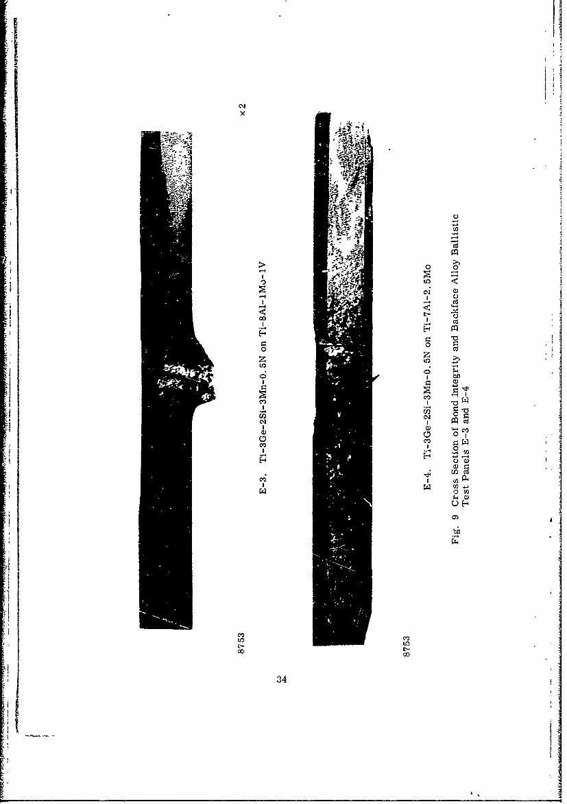
9 Cross Section of Bond Integrity and Backface Alloy BallisticTest Panels E-3 and E-4 34
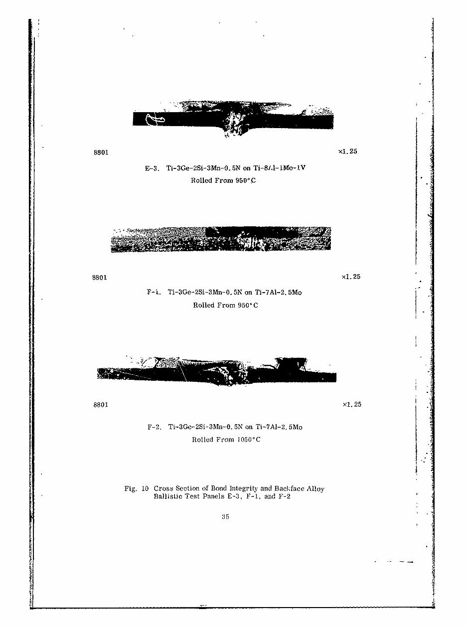
10 Cross Section of Bond Integrity and Backface Alloy BallisticTest Panels E-3, F-i, and F-2 35
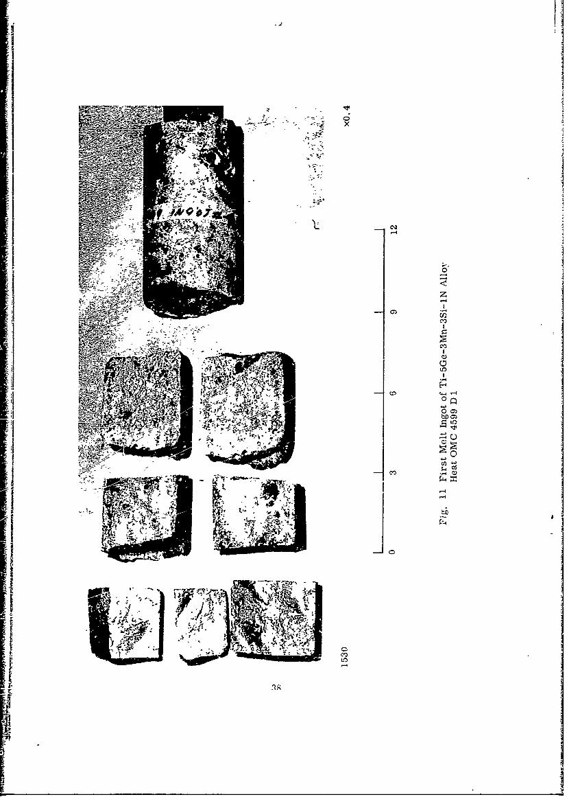
11 First Melt Ingot of Ti-5Ge-3Mn-3Si-1N Alloy, HeatOMC 4599 D1 38
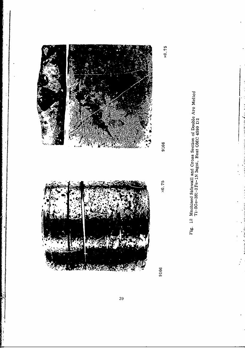
12 Machined Sidewall and Cross Section of Double Arc MeltedTi-5Ge-3Si-3Fe-1N Ingot, Heat OMC 4599 D2 39
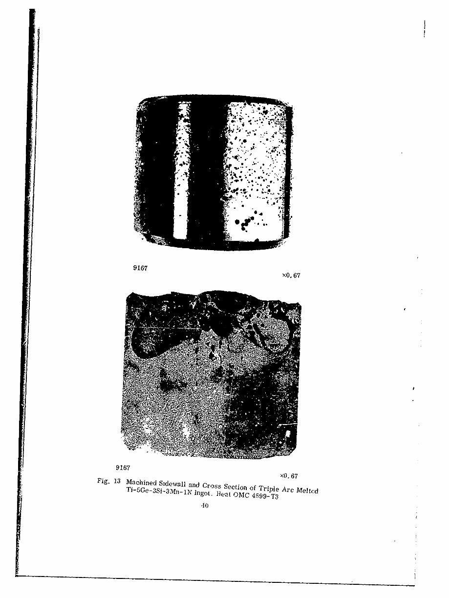
13 Machined Sidewall and Cross Section of Triple Arc Melted1 Ti-5Ge-3Si-3Mn-1N Ingot, Heat OMC 4599-T3 40
14 Appearance of Ballistic Test Plates, As-Diffusion Bonded
and As-Rolled 44
15 Effect of Heat Treatment on the Hardness and Toughness ofTi-7A1 -2. Mo 0.4-in. -Thick Plate 48
ix
I ~ -i
Figure Page
16 Appearance of 50-cal AP Test Plate TP-5 Hit at 1,740(Center) and 1,585 (Lower Left) ft/sec. Hardness- IRc 56-57 51
17 Cross Section of 50-cal AP Test Plate TP-5 ThroughImpact Crater of Hit at 1,585 ft/sec 52
I18 Appearance of 50-ca AP Test Plates TP-1 and TP-7 5319 Appearance of 30-cal AP Test Plates TP-2 and TP-3 54 120 Appearance of 30-cal AP Test Plates TP-4 and TP-8 55
21 Appearance of 30-cal AP Test Plate TP-6 56
22 Hardness Profiles of Dual-Hardness Titanium Alloy BallisticTest Panels 59
23 Microstructure of Hard Face Alloys in Heat-Treated BallisticTest Plates 60
24 Microstructural Details of Hard Face Alloys in Heat-TreatedBallistic Test Plates 61
25 Microstructure of Ti-7A1-2. Mo Back Face Alloy in Heat-Treated Ballistic Test Plates 62
26 Microstructures at the Bond Line of Heat-Treated BallisticTest Plates 63
27 Microstructural Details of the Bond Line in Heat-TreatedBallistic Test Plates 64
28 Selective Cracking of the Alpha Phase Near the SurfaceAdjacent to a 50-cal AP Hit on Test Plate TP-5 65
xA
I.
TABLES
: Tale Page
I Effect of Ge:Si Ratio on Hardness 7
2 Effect of Composition on Ha Iness and Flardenability ofExperimental Hard-Face Alloys 8
3 Alloy Recovery in Melting of Hard-Face Alloys 13
4 Effect of Ge and N Content on the Heat-Treatment Responseof Experimental Hard-Face Alloys 19
5 Aging Response of Ti-3Ge-3Mn-2Si-1N Alloy 20
6 Heat-Treatanent ':esponse of a Ti-3Ge-3Mn--2Si-0. 5 Alloy 22
7 Candidate Alloys for Back Face 23
a Effect of Rolling Temperature and Heat Treatment onHardness and Toughness of Back-Face Alloys 24
9 Summary of 30-cal AP/M2 Ballistic Evaluation Studies 27
10 Evaluation Data for Ti-3Ge-3Mn-2Si-O. 5N/Ti-7AI-2.5MoDual-Hardness Composite Armor 33
11 Summary Processing Data of Dual-Hardness Titanium AlloyComposite Ballistic Test Panels 43
12 Results of 0. 50- and 0.30-Caliber AP/M2 Ballistic Tests onDual-Hardness Titanium Alloy Composite Armor Performedat AMMRC 47
13 Microhardness of Titanium Alloy Composite Ballistit: TestPanels 58
xi
I- - . * -
Section 1
INTRODUCTION
1.1 BACKGROUND
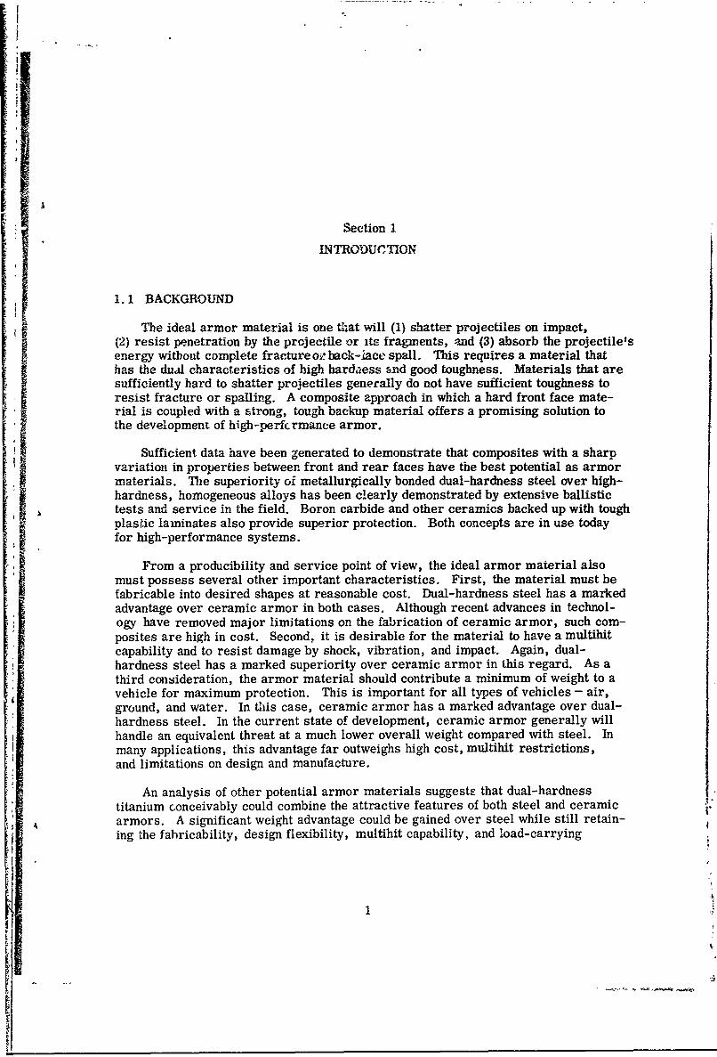
The ideal armor material is one that will (1) shatter projectiles on impact,(2) resist penetration by the projectile or its fragments, and (3) absorb the projectile'senergy without complete fractureozback-iace spall. This requires a material thathas the dual characteristics of high hardaess and good toughness. Materials that aresufficiently hard to shatter projectiles generally do not have sufficient toughness toresist fracture or spalling. A composite approach in which a hard front face mate-rial is coupled with a strong, tough backup material offers a promising solution tothe development of high-perfcrmance armor.
Sufficient data have been generated to demonstrate that composites with a sharp
variation in properties between front and rear faces have the best potential as armormaterials. Tie superiority oi metallurgically bonded dual-hardness steel over high-hardness, homogeneous alloys has been clearly demonstrated by extensive ballistictests and service in the field. Boron carbide and other ceramics backed up with toughplasic laminates also provide superior protection. Both concepts are in use today~for high-performance systems.
From a producibility and service point of view, the ideal armor material alsomust possess several other important characteristics. First, the material must befabricable into desired shapes at reasonable cost. Dual-hardness steel has a markedadvantage over ceramic armor in both cases. Although recent advances in technol-
ogy have removed major limitations on the fabrication of ceramic armor, such com-posites are high in cost. Second, it is desirable for the material to have a multihitcapability and to resist damage by shock, vibration, and impact. Again, dual-hardness steel has a marked superiority over ceramic armor in this regard. As athird consideration, the armor material should contribute a minimum of weight to avehicle for maximum protection. This is important for all types of vehicles - air,ground, and water. In this case, ceramic armor has a marked advantage over dual-hardness steel. In the current state of development, ceramic armor generally willhandle an equivalent threat at a much lower overall weight compared with steel. Inmany applications, this advantage far outweighs high cost, multihit restrictions,and limitations on design and manufacture.
An analysis of other potential armor materials suggests that dual-hardnesstitanium conceivably could combine the attractive features of both steel and ceramicarmors. A significant weight advantage could be gained over steel while still retain-
ing the fabricability, design flexibility, multihit capability, and load-carrying
-f 9
A 1E
ability of an all-metallic system. For equivalent armor thicknesses, titanium willhave about 60% the weight of steel, which gives a 40% weight savings in armoredsystems. Although somewhat heavier than ceramic armor at equivalent thicknesses,a titanium armor system conceivably could have less total weight since the ceramicarmor must be used as an overlay on a load-carrying structure. The metallic armor,on the other hand, can be used as the load-carrying member itself. Although moreexpensive than steel, titanium armor materials will be significantly less expensivethan ceramic armors. This will be particularly true when producibility, design, andmanufacturing requirements are taken into consideration.
Although considerable effort has been devoted to the development of titaniumalloys for armor, none of the materials disclosed to date have been capable of defeat-ing high-velocity projectiles by a fracture mechanism. Intermediate-hardness alloyshave been used to defeat projectiles by resisting penetration. Titanium alloys ofsufficiently high hardness to shatter projectiles have not been produced. Based onthe current theory of defeat mechanisms in dual-hardness steel and composite ceramicarmor, the hardness of the front face should approach the hardness of the steelpenetrator (i. e., Rc 65 - 70). The highest values reported for titanium alloys arein the range of Rc 50 - 55. In addition, alloy compositions that can be hardened tothis range tend to be very brittle and are subject to cracking as a result of high stress
generated from thermal gradients encountered in melting and fabrication. Theinability to produce titanium alloys at hardness levels above Rc 55 has precluded thedevelopment of an effective dual-hardness titanium armor.
In 1968, the Lockheed Palo Alto Research Laboratory undertook a study of newapproaches to the design of high-hardness titanium alloys suitable for dual-hardnessarmor. The result was the development of a new class of alloys containing Ge, Si,Mn, and N which were harder. d by a combination of mechanisms, including(1) solid solution alloying, (2) phase transformation, (3) formation of a hard-phasedispersion, and (4) intermetallic compound precipitation. The alloys could be solu-tion annealed to a semihard condition (Re 45 - 55) for fabrication and subsequentlyaged to full hardness (Rc 55 - 65). This is the highest level of hardness that has beenreported for a wrought, heat-treatable titanium-base alloy. A small plate of onealloy was diffusion bonded to commercial Ti-8A1-lMo-1V alloy plate and the com-posite hot rolled 70% into 0. 1-in. -thick plate with a 50:50 ratio of hard-to-soft facethicknesses. The hardness after heat treatment was Rc 62 - 64 for the front faceand Re 46 - 48 for the soft face. A good metallurgical bond was obtained with agradual change in hardness across the interface.
The discovery of this new class of alloys and their utilization in producing adual-hardness composite that approaches the hardness level of steel armor repre-sent potentially significant advances in titanium armor technology. It appears thatthe development of an effective dual-hardness titanium armor may now be feasible.An evaluation of the producibility of these alloys in ingot form and their ballisticperformance as composite test panels is required to define more clearly the poten-tial of this approach. The present investigation was designed to meet this need.
2
1.2 OBJECTIVE AND SCOPE
The objective of this program was to establish the technical feasibility of produc-ing an effective dual-hardness titanium armor utilizing a new class of high-hardnesstitanium alloys. Alloys in the system Ti, 3 - 5% Ge, 2 - 3% Si, 3 - 7% Mn (or Fe),and 0.5 - 1.25% N were screened with respect to hardness and heat treatmentresponse to permit selection of front face compositions that could be hardened tothree different Rc levels: 55 - 60, 60 - 65, and > 65. Methods for arc melting4- to 6-in. -diameter ingots weighing 18 t- 25 lb and for press forging and rollingthese ingots into plate were studied. The compatibility of working and heat-treatmentprocedures with commercial back-face alloys also was considered. Back-face alloycandidates were screened for similar compatibility characteristics as well as fortoughness and for ballistic performance. In addition, processing schedules for diffu-sion and roll bonding the hard- and soft-face alloys into composite plate wereestablished.
Materials and procedures selected on the basis of these studies were used toprepare eight ballistic test panels measuring 5 by 5 by 0.625 in. for testing andevaluation. The plates were subjected to ballistic tests using 0.30- and 0.50-calAP-M2 projectiles at the Army Materials and Mechanics Research Center, Watertown,Mass. Results were correlated with hardness, structure, and composition of boththe front and rear faces and the nature of the bond interface to serve as a guide forfuture development of these materials. The results of this program indicate goodtechnical feasibility for the manufacture of an effective dual-hardness titanium armor,and recommendations for further development of this concept are presented.
3
Section 2
MATERIALS AND PROCESS DEVELOPMENT
2.1 HARD-FACE ALLOYS
2.1.1 Technical Background
Significant hardening in titanium is developed by (1) interstitial alloying withC, 0, .and N, (2) the omega transition. phase, and (3) precipitati3n of coherent.intermetallic compound particles. In the first method, nitrogen is the most potenthardener. The degree of hardening achieved with this element increases proportion-ately with increasing nitrogen content and reaches a maximum at the saturation value.A saturated solid solution of nitrogen in alpha titanium has a hardness of Rc 66 to 68;the saturated solid solution of beta which transforms to alpha on cooling has a hard-ness of Rc 52- 55 (Ref. 1). Nitrogen also reduces the ductility of titanium andincreases the ductile-to-brittle transition temperature. In general, nitrogen harden-ing occurs only at low temperatures; high nitrogen alloys are soft and ductile atelevated temperatures. At sufficiently high nitrogen contents, the ductile-to-brittletransition temperature exceeds the normal range for hot working titanium, and thealloys cannot be fabricated. Studies at the Lockheed Palo Alto Research Laboratoryhave shown that up to 2.0 wt% nitrogen can be added to unalloyed titanium withoutcomplete loss of ductility. Such alloys have marginal hot workability. At a level of1.0 to 1.5 wt% N in titanium, the alloys have good ductility at high temperatures andcan be readily hot worked and formed. The base hardness of binary titanium-nitrogenalloys in the range of 1. 0 - 1. 5 wt% N is Rc 45 to 50.
The hardening of titanium by heat treatment depends primarily on the rate ofdecomposition of the beta phase (method 2). Control of this reaction is facilitated bythe addition of appropriate substitutional-type solute elements (beta stabilizers),which retard the 3 - a transformation. During this reaction, a hard transitionphase known as omega has been observed to form (i. e., 13 - w + a) in a number ofalloy systems including Ti-Fe, Ti-Cr, Ti-V, Ti-Mo, and Ti-Ni (Ref. 2). Hard-ness levels of alloys containing this phase have been reported in the literature toapproach 57 Rc (Ref. 3), the highest values being developed in the Ti-Fe system(Ref. 4). Alloys hardened by this mechanism also tend to be extremely brittle.This hardness is still well below the level of Rc 60 - 65 desired for a hard-facealloy.
Compound precipitation (method 3) has not been particularly effective in hardeningtitanium alloys. Studies have been made with both hypoeutectoid and hypereutectoidalloys in the Ti-Si, Ti-Ge, Ti-Ni, Ti-Cu, Ti-Co, and Ti--Cr systems. Workperformed at the Lockheed Palo Alto Research Laboratory has shown that hardnesslevels of 35 to 47 Re can be achieved in Ti-20 Cr, Ti-15 Co, and Ti-10 Ge alloys
't4
hen isothermally aged following solution treatment. Hardening in thi.s instance isderived from the development of a coherent, WidmanstitiZ distribution of Ti Cr 2and TiqCo platelets in a beta matrix and TisGe 3 precipitates in an alpha matrix.The latter alloy was particularly effective and hardened from Rc 31 to Re 47 onisothermal aging at 925°C.
Although none of the aforementioned methods by itself yields a hardness in thetarget range of Re 60 to 65, the potential for achieving such a goal through a combina-tion of methods appeared promising; such an approach in other alloy systems hasindicated that the effects derived from different hardening mechanismo are generallyadditive. To test this hypothesis, the additive effects of interstitial, omega, andprecipitation hardening were studied. Titanium-germanium alloys were selected asa base because of their good age-hardening response. Nitrogen was selected as theinterstitial hardener, and Mn, Fe, V, and Cr were evaluated as beta stabilizers.Alloys ranging in hardness from Rc 47 to 64 were produced. The aging response,however, was lower than desired, and the hardest allcys (high germanium) wereexcessively brittle.
In seeking to improve the balance between toughness and hardness and to increasethe response to aging, silicon was added as a replacement for part of the germanium.Of the many alloys studied, only two compositions (Ti-5Ge-2Fe-2Si-lN andTi-5Ge-3Mn-2Si-IN) exhibited the desired combination of hardness and resistanceto cracking. The hardness of these alloys ranged from Rc 56 - 59 in the solution-annealed condition (water quenched from 10000C) to Rc 60 - 64 in the fully agedcondition (2 hr at 4000 C ). The alloys were not sensitive to thermal shock anddemonstrated relatively good resistance to fracture on impact.
The microstructure of these alloys as quenched from 1000 - 11000C and aged at4000C consisted of nearly equal amounts of equiaxed alpha and alpha prime (marten-site). The latter is an extremely fine transformed beta structure which can beresolved at a magnification of 3000 x. Typical microstructures of these alloys are fshown in Figs. 23, 24, and 28. The average diameters of the alpha and prior betagrains were 10 - 2011. The ultrafine structure appeared to result from growthresistrictions imposed on these phases by intermetallic compound particles. A third
phase, most likely Ti 5 (Ge,Si)3 , with an average particle size of 411 was randomlydistributed in the prior beta grains and in the boundaries between the alpha and alphaprime (martensite) regions. It is believed that the fineness of the structure, coupledwith the fact that the hard and brittle compound phases do not form a continuousnetwork, accounts for the reasonably good toughness of the alloy.
As a result of these studies, a new and unique class of wrought titanium alloyshas been developed. For the first time, a wrought tit-anium alloy has been produced
with a hardness approaching that of steel armor piercing projectiles and dual-hardness steel armor plate. The materials also have reasonable toughness. Thebest alloys developed to date contain less than 10% total alloy contenlt with the com-positions Ti/3-5%Ge/1-2%Si/2-4%Mn or Fe, and 0.5-1. 5%N. Measured densities
5
are in the range of 5.0 to 5.1 gm/cc (0.18-0. 185 lb/in. 3). At a thickness of0. 3125-in. (1/2 of a 5/8-in. -thick dual-hardness plate), the alloy weighs 8.14 to8.28 lb/ft2 . If backed with an equivalent thickness of a tough titanium alloy such ascommercial Ti-8A-1Mo-IV, a dual-hardness armor plate, 5/8 in. thick wouldweigh 15.3 to 1545 lb/f; - . This is oely 3.5 to 4.75-% more than unalloyed titaniumand is 59 to 60% we weight of dual-hardness steel. Thus, if effective as an armormaterial, up to a 40% weight saving could be realized.
T-ese initial alloy development studies contacted by the Lockheed Palo AltoResearch Laboratory in 1968 were exploratory in nature and merely served to definea new class of alloys, potentially useful for dual-hardness armor. The range ofcompositions within which the desired combination of properties is produced and theoptimum processing procedures for melting, fabrication, and heat treatment werenot defined. T.he work required to optimize compositions and processirg variableswas conducted under the current contract and the results are presented in the follow-ing sections of this report.
2.1.2 Alloy Selection
The effect of compositional variations on the hardness and hardenability of thebasic Ti-5Ge--2Si-3Mn(Fe)-1N alloy was studied to aid in the selection of the candi-date hard-face alloys. The Ge:Si ratio was investigated first to determine theextent to which germanium could be replaced by silicon and to establish optimumratios. Six alloys were prepared with Ge:Si ratios (based on weight percent)ranging from zero to infinity. The total alloy content ranged from 4 to 10 wt%.Substitution was made on the basis of 1. 0 wt% Ge being equivalent to 2.5 wt% Si,which is the direct ratio of molecular weights of the two elements. Starting with aTi-lOGe-3Mn-1N base, silicon was subsrituted for Ge on the basis of this equiva-lence. The alloy at zero Ge:Si ratio was Ti-4Si-3Mn-IN. Samples of rolled0. 150-in. -thick plate were solution annealed 10 min at 11000 and/or 12000C andaged 2 hr at 4000C. The results of hardness tests are presented in Table 1.
Preliminary studies had indicated that at least 2 wt% Si was needed in aTi-SGe-3Mn-IN alloy for optimum aging response and high hardness. The datashown in Table 1 confirm these earliErr fin&ngs. Alloys containing only Ge or Sihad the lowest hardness and aging resioase. Maximum hardness on quenching from11000C occurred at a Ge:Si ratio of 2.5:1, and the maximum aging response occurredat this ratio when the alloys were quenched from 12000C. The data indicate that a1:1 Ge:Si ratio is capable of retaining acceptable properties in these alloys. Thegermanium content can be lowered to about 2. 5 wt% and the silicon increased to3.0 wt% without major detriment to the alloy. Better properties are achieved, how-ever, at a level of 5 wt% Ge and 2 wt% Si.
A complete substitution of Si for Ge does not appear to be desirable from thestandpoint of either producibility or hardness. The Ti-4Si-3Mn-IN alloy was verysusceptible to thermal shock cracking on rapid heating or cooling and was difficult to
6
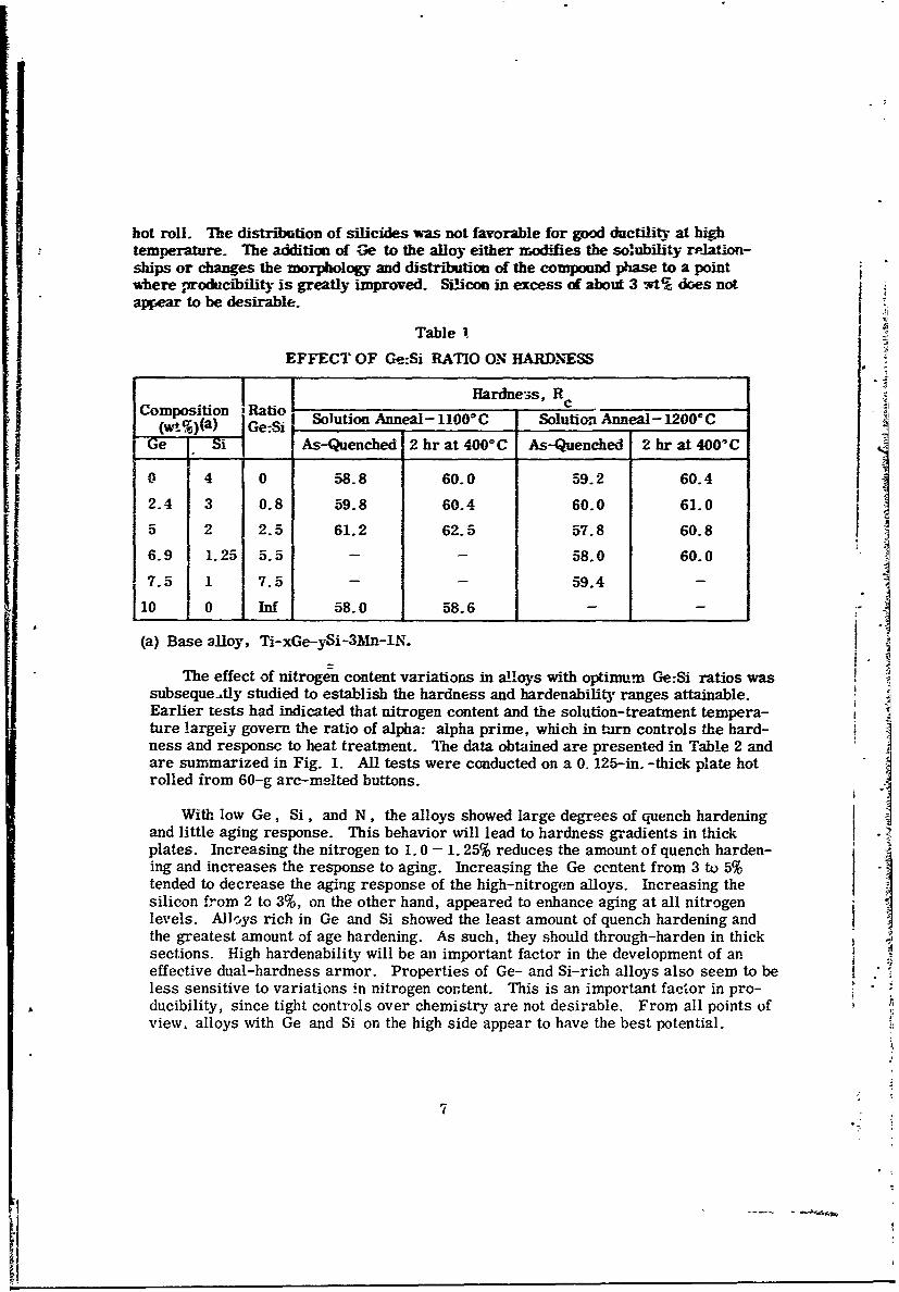
hot roll. The distribution of silicides was not favorable for good ductility at hightemperature. The addition of Ge to the alloy either modifies the solubility rplation-ships or changes the morphology and distribution of the commpound phase to a pointwhere ,roducibility is greatly improved. Silicon in excess of about 3 vt% does notappear to be desirable.
Table 1
EFFECT OF Ge:Si RATIO ON HARDNESS
Hardness, RComposition 1 c
w,%(ASolution Anneal- 1100 C Solutio Anneal - 1200* C
.Si As-Quenched 2 hr at 400'C As-Quenched 2 hr at 400'C
0 4 0 58-8 60.0 59.2 60.4
2-4 3 0.8 59.8 60.4 60.0 61.0
5 2 2.5 61.2 62.5 57.8 60.8
6.9 1.25 5.5 - - 58.0 60.07 5 1 7.5 - - 59.4
0 Inf 58.0 58.6 -
(a) Base alloy, Ti-xGe-ySi-3Mn-1N.
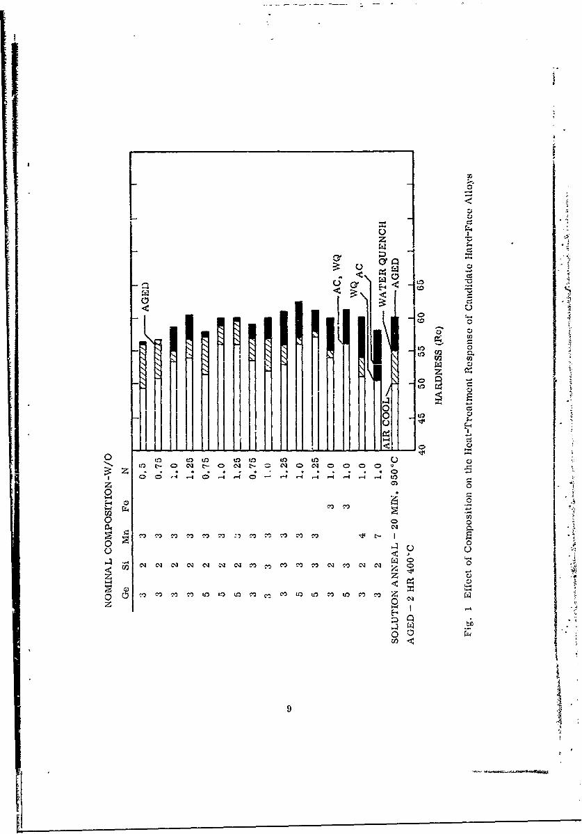
The effect of nitrogen content variations in alloys with optimum Ge:Si ratios wassubsequently studied to establish the hardness and hardenability ranges attainable.Earlier tests had indicated that nitrogen content and the solution-treatment tempera-ture largely govern the ratio of alpha: alpha prime, which in trn controls the hard-ness and responsc to heat treatment. The data obtained are presented in Table 2 andare summarized in Fig. 1. All tests were conducted on a 0. 125-in. -thick plate hotrolled from 60-g arc-melted buttons.
With low Ge, Si, and N, the alloys showed large degrees of quench hardeningand little aging response. This behavior will lead to hardness gradients in thickplates. Increasing the nitrogen to 1.0 - 1. 25% reduces the amount of quench harden-ing and increases the response to aging. Increasing the Ge content from 3 to 5%tended to decrease the aging response of the high-nitrogen alloys. Increasing thesilicon from 2 to 3%, on the other hand, appeared to enhance aging at all nitrogenlevels. Alloys rich in Ge and Si showed the least amount of quench hardening andthe greatest amount of age hardening. As such, they should through-harden in thicksections. High hardenability will be an important factor in the development of aneffective dual-hardness armor. Properties of Ge- and Si-rich alloys also seem to beless sensitive to variations in nitrogen content. This is an important factor in pro-
A ducibility, since tight controls over chemistry are not desirable. From all points ofview, alloys with Ge and Si on the high side appear to have the best potential.
I7
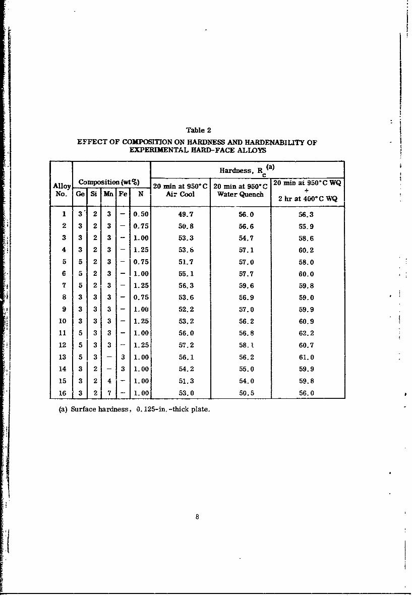
Table 2
EFFECT OF COMPOSITION ON HARDNESS AND HARDENABILITY OFEXPERIMENTAL HARD-FACE ALLOYS
Hardness, R (a)C
Copsto (wco 20I2ODat95OC 2C WatAlloy 20 min at 950C 20 in at 950Ci9 CWQNo. Ge Si IMn Fe N Air Cool Water Quench 2h t40CWNo. e Si2 hr at 400"C WQ
1 3' 2 3 - 0.50 49.7 56.0 56.3
2 3 2 3 - 0.75 50.8 56.6 55.9
3 3 2 3 - 1.00 53.3 54.7 58.6
4 3 2 3 - 1.25 53.6 57.1 60.2
5 5 2 3 - 10.75 51.7 57.0 58.0
6 5 2 3 - 1.00 55.1 57.7 60.0
7 5 2 3 - 1.25 56.3 59.6 59.8
8 3 3 3 - 0.75 53.6 56.9 59.0
9 3 3 3 - 1.00 52.2 57.0 59.9
10 3 3 3 - 1.25 53.2 56.2 60.9
11 5 3 3 - 1.00 56.0 56.8 62.2
12 5 3 3 -- 1.25 5-7.2 58.1 60.7
13 5 3 - 3 1.00 56.1 56.2 61.0
14 3 2 - 3 1.00 54.2 55.0 59.9
15 3 2 4j- 1.00 51.3 54.0 59.8
16 3 2 7 -- 1.00 53.0 50.5 56.0
(a) Surface hardness, 0. 125-in. -thick plate.
8
no°
L~LO
OL U° o
3 LO
,~I 0,_,0
z
-1 -4 -- 530 C
-4
0
riZ,
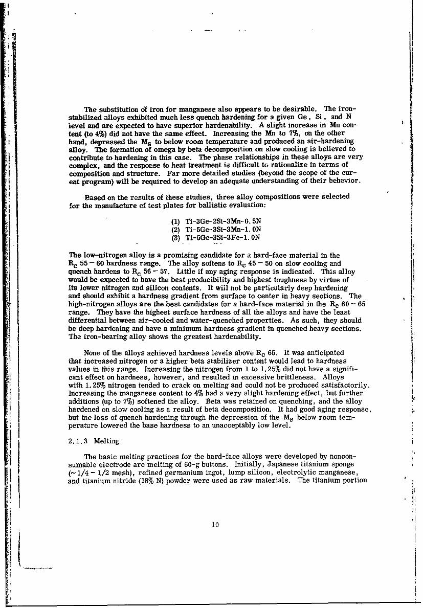
The substitution of iron for manganese also appears to be desirable. The iron-stabilized alloys exhibited much less quench hardening for a given Ge, Si, and Nlevel and are expected to have superior hardenability. A slight increase in Mn con-tent (to 4%) did not have the same effect. Increasing the Mn to 7%, on the otherhand, depressed the Ms to below room temperature and produced an air-hardeningalloy. The formation of omega by beta decomposition on slow cooling is believed tocontribute to hardening in this case. The phase relationships in these alloys are verycomplex, and the response to heat treatment is difficult to rationalize in terms ofcomposition and structure. Far more detailed studies (beyond the scope of the cur-ent program) will be required to develop an adequate understanding of their behavior.
Based on the results of these studies, three alloy compositions were selectedfor the manufacture of test plates for ballistic evaluation:
(1) Ti-3Ge-2Si-3Mn-O. 5N(2) Ti-5Ge-3Si-3Mn-1. ON(3) Ti-5Ge-3Si-3Fe-1. ON
The low-nitrogen alloy is a promising candidate for a hard-face material in theRe 55 - 60 hardness range. The alloy softens to Rc 45 - 50 on slow cooling andquench hardens to Rc 56 - 57. Little if any aging response is indicated. This alloywould be expected to have the best producibility and highest toughness by virtue ofits lower nitrogen and silicon contents. It will not be particularly deep hardeningand should exhibit a hardness gradient from surface to center in heavy sections. Thehigh-nitrogen alloys are the best candidates for a hard-face material in the Rc 60 - 65range. They have the highest surface hardness of all the alloys and have the leastdifferential between air-cooled and water-quenched properties. As such, they shouldbe deep hardening and have a minimum hardness gradient in quenched heavy sections.The iron-bearing alloy shows the greatest hardenability.
None of the alloys achieved hardness levels above Rc 65. It was anticipatedthat increased nitrogen or a higher beta stabilizer content would lead to hardnessvalues in this range. Increasing the nitrogen from 1 to 1.25% did not have a signifi-cant effect on hardness, however, and resulted in excessive brittleness. Alloyswith 1.25% nitrogen tended to crack on melting and could not be produced satisfactorily.Increasing the manganese content to 4% had a very slight hardening effect, but furtheradditions (up to 7%) softened the alloy. Beta was retained on quenching, and the alloyhardened on slow cooling as a result of beta decomposition. It had good aging response,but the loss of quench hardening through the depression of the Ms below room tem-perature lowered the base hardness to an unacceptably low level.
2.1.3 Melting
The basic melting practices for the hard-face alloys were developed by noncon-
sumable electrode arc melting of 60-g buttons. Initially, Japanese titanium sponge(- 1/4 - 1/2 mesh), refined germanium ingot, lump silicon, electrolytic manganese,and titanium nitride (18% N) powder were used as raw materials. The titanium portion
At 10
i-
of each charge was premelted into a button, sectioned in half, and each half drilled topermit incorporation of the fine TiN powder master alloy. This procedure wasnecessary to prevent the TiN from blowing away under the arc during melting. Allcharge components were then placed in the melting cavity of a water-cooled copperhearth and melted under helium at a pressure of about 0.75-0.8 atm. 1he buttonwas melted for 2 min on each side and was then cut in half, placed on end, andremelted. This process was repeated witil a button of uniform composition free ofcracks was produced.
Alloying with nitrogen proved to be a major problem. Titanium nitride wasdifficult to dissolve, and segregated regions rich in nitrogen were formed. Theseregions tended to crack on cooling or on remelting and had to be eliminated. Up toeight remelts with sectioning of the button between melts were required to producehomogeneous alloys free of cracks. It was apparent that sound ingots could not beproduced using this approach. Consideration was given to the preparation of a lowernitrogen content master alloy to solve this problem. However, preparation of ahomogeneous master alloy presented as many difficulties. As a result, other sourcesof nitrogen for alloying with titanium were considered.
The other ingredients of the alloy (Si, Ge, Mn, or Fe) form lower meltingalloys and/or compounds with nitrogen and were considered to be a better source forintroducing this element. Since silicon nitride (Si 3N4 ) is a commercial productavailable in a standard high-purity grade (39% N), it was selected for initial studies.Button melting tests similar to those described previously revealed that silicon nitridealloyed readily with titanium. Premelting of the titanium for alloying with the nitride,as previously discussed, was not required when Si 3N4 was used as the nitrogen addi-tion agent. In one test, no segregation was detected after the initial double melt(from two sides) of a 60-g charge of a Ti-5Ge-2Si-3Mn-IN alloy. Problems withingot cracking and the necessity of repeated melting for homogenization were elimi-nated. Silicon nitride, therefore, was selected as the addition agent for nitrogen inpreparing the alloys. No further problems with cracking as a result of nitrogensegregation were encountered in preparing 60-g buttons for the remainder of theprogram.
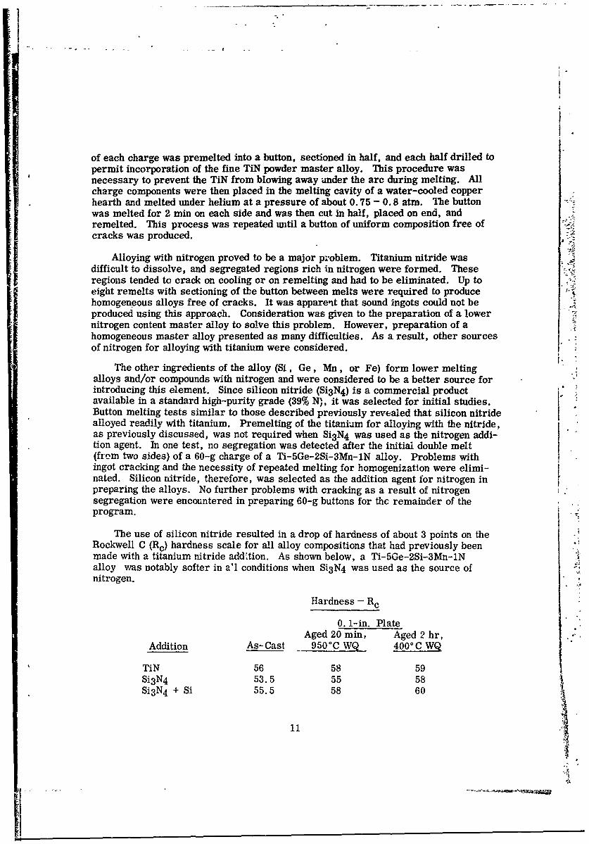
The use of silicon nitride resulted in a drop of hardness of about 3 points on theRockwell C (Rc) hardness scale for all alloy compositions that had previously been
made with a titanium nitride add',tion. As shown below, a Ti-5Ge-2Si-3Mn-INalloy vras notably softer in a'l conditions when Si 3 N4 was used as the source ofnitrogen.
Hardness - Rc
0.1-in. PlateAged 20 rin, Aged 2 hr,
Addition As-Cast 950°C WQ 4000 C WQ
TiN 56 58 59Si 3 N4 53.5 55 58Si 3 N4 + Si 55.5 58 60
11V
Since silicon is known to be an important hardener, it was postulated that a lowrecovery of silicon might be responsible for this effect. The charge calculation forsilicon was based on full recovery of all the silicon from the nitride. If the recoverywere low, the hardness wold drop as shown. In one test, 50% excess silicon was
added on the assumption that none of the silicon from the Si3 N4 would be recovered.As shown above, the hardness of this alloy was identical to that of earlier alloys pre-pared with a TiN addition.
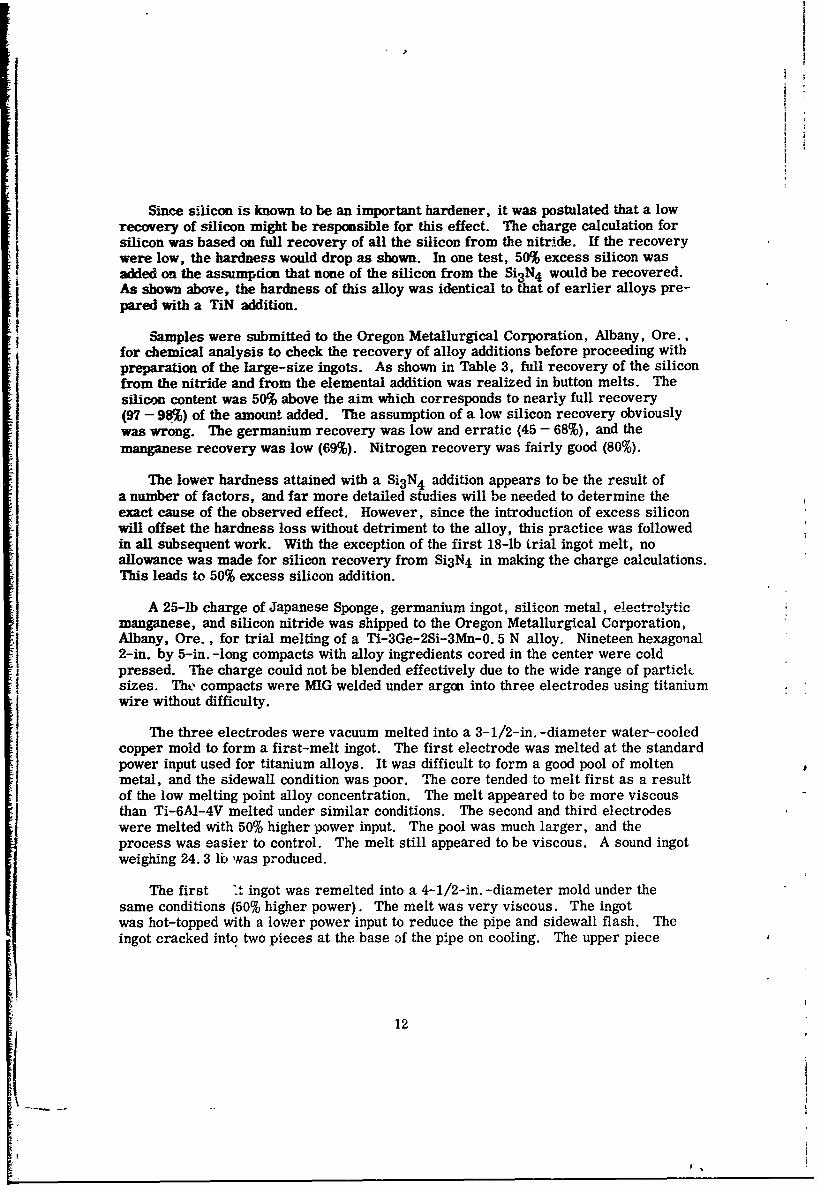
Samples were submitted to the Oregon Metallurgical Corporation, Albany, Ore.,for chemical analysis to check the recovery of alloy additions before proceeding withpreparation of the large-size ingots. As shown in Table 3, full recovery of the siliconfrom the nitride and from the elemental addition was realized in button melts. Thesilicon content was 50% above the aim which corresponds to nearly full recovery(97 - 98%) of the amount added. The assumption of a low silicon recovery obviouslywas wrong. The germanium recovery was low and erratic (45 - 68%), and themanganese recovery was low (69%). Nitrogen recovery was fairly good (80%).
The lower hardness attained with a Si 3N4 addition appears to be the result ofa number of factors, and far more detailed studies will be needed to determine theexact cause of the observed effect. However, since the introduction of excess siliconwill offset the hardness loss without detriment to the alloy, this practice was followedin all subsequent work. With the exception of the first 18-lb trial ingot melt, noallowance was made for silicon recovery from Si 3 N4 in making the charge calculations.This leads to 50% excess silicon addition.
A 25-lb charge of Japanese Sponge, germanium ingot, silicon metal, electrolyticmanganese, and silicon nitride was shipped to the Oregon Metallurgical Corporation,Albany, Ore., for trial melting of a Ti-3Ge-2Si-3Mn-0. 5 N alloy. Nineteen hexagonal2-in. by 5-in. -long compacts with alloy ingredients cored in the center were coldpressed. The charge could not be blended effectively due to the wide range of particlsizes. The compacts were MIG welded under argon into three electrodes using titaniumwire without difficulty.
The three electrodes were vacuum melted into a 3-1/2-in. -diameter water-cooledcopper mold to form a first-melt ingot. The first electrode was melted at the standardpower input used for titanium alloys. It was difficult to form a good pool of moltenmetal, and the sidewall condition was poor. The core tended to melt first as a resultof the low melting point alloy concentration. The melt appeared to be more viscousthan Ti-6AI-4V melted under similar conditions. The second and third electrodeswere melted with 50% higher power input. The pool was much larger, and theprocess was easier to control. The melt still appeared to be viscous. A sound ingotweighing 24.3 lb was produced.
The first :'. ingot was remelted into a 4-1/2-in. -diameter mold under thesame conditions (50% higher power). The melt was very viscous. The ingotwas hot-topped with a lower power input to reduce the pipe and sidewall flash. Theingot cracked into two pieces at the base of the pipe on cooling. The upper piece
12
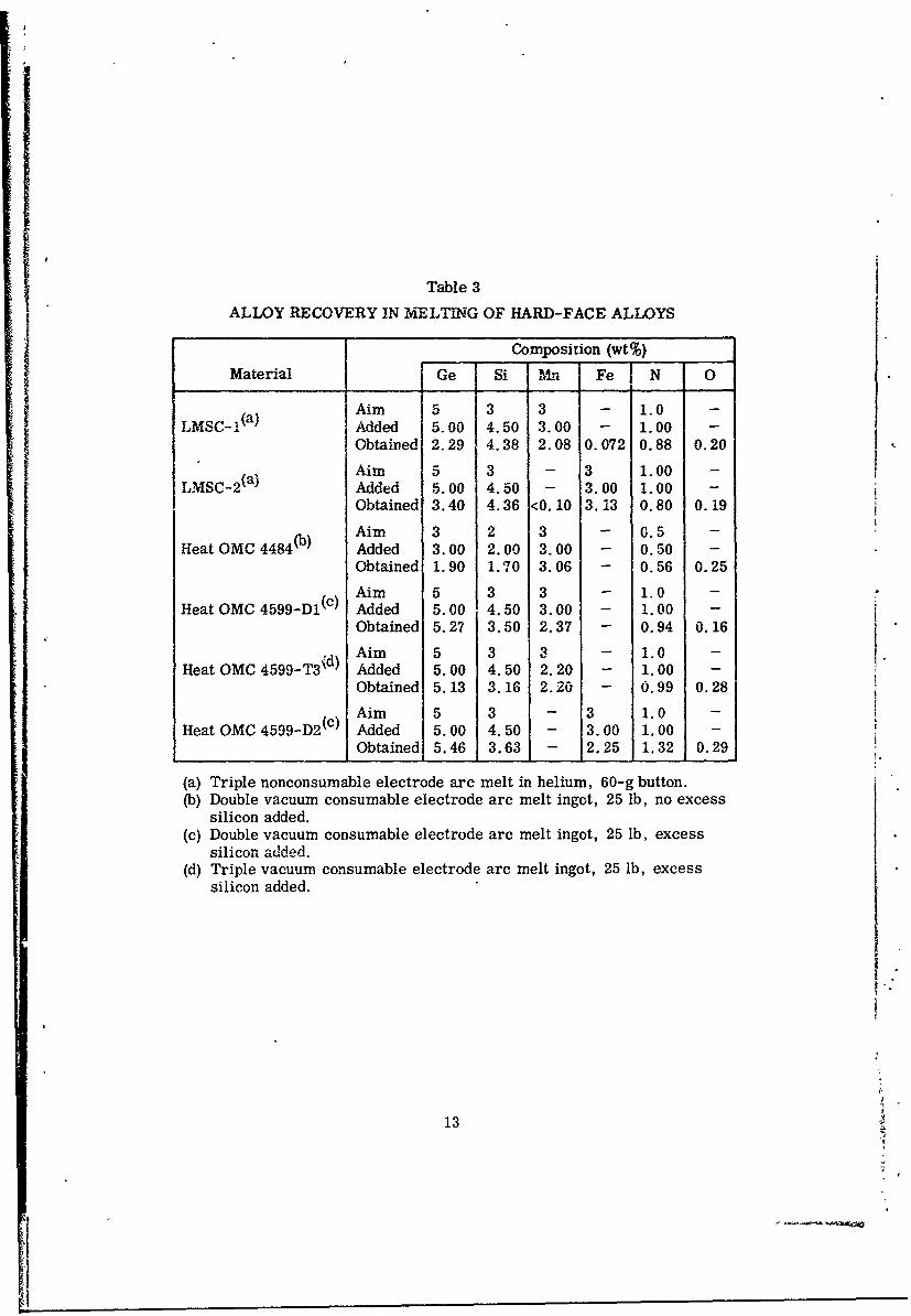
Table 3
ALLOY RECOVERY IN MELTIG OF HARD-FACE ALLOYS
Composition (wt%)
Material jGe Si Mn Fe N 0
Aim 5 3 3 - 1.0 -
LMSC-1(a ) Added 5.00 4.50 3.00 - 1.00 -
Obtained 2.29 4.38 2.08 0.072 0.88 0.20
Aim 5 3 - 3 1.00 -LMSC2 (a) Added 5.00 4.50 - 3.00 1.00 -
Obtained 3.40 4.36 <0.10 3.13 0.80 0.19
Aim 3 2 3 - G.5 -Heat OMC 4484 w j Added 3.00 2.00 3.00 - 0.50 -
Obtained 1.90 1.70 3.06 - 0.56 0.25
Aim 5 3 3 - 1.0 -Heat OMC 4599-D1(c) Added 5.00 4.50 3.00 - 1.00 -
Obtained 5.27 3.50 2.37 - 0.94 0.16
Aim 5 3 3 - 1.0 -.Heat OMC 4599-T3 \d) Added 5.00 4.50 2.20 - 1.00 -
Obtained 5.13 3.16 2.20 - 0.99 0.28
Aim 5 3 - 3 1.0 -
Heat OMC 4 59 9 -D2(c) Added 5.00 4.50 - 3.00 1. 00 -
Obtained 5.46 3.63 - 2.25 1.32 0.29
(a) Triple nonconsumable electrode arc melt in helium, 60-g button.(b) Double vacuum consumable electrode arc melt ingot, 25 lb, no excess
silicon added.(c) Double vacuum consumable electrode arc melt ingot, 25 lb, excess
silicon added.(d) Triple vacuum consumable electrode arc melt ingot, 25 lb, excess
silicon added.
13
I¢
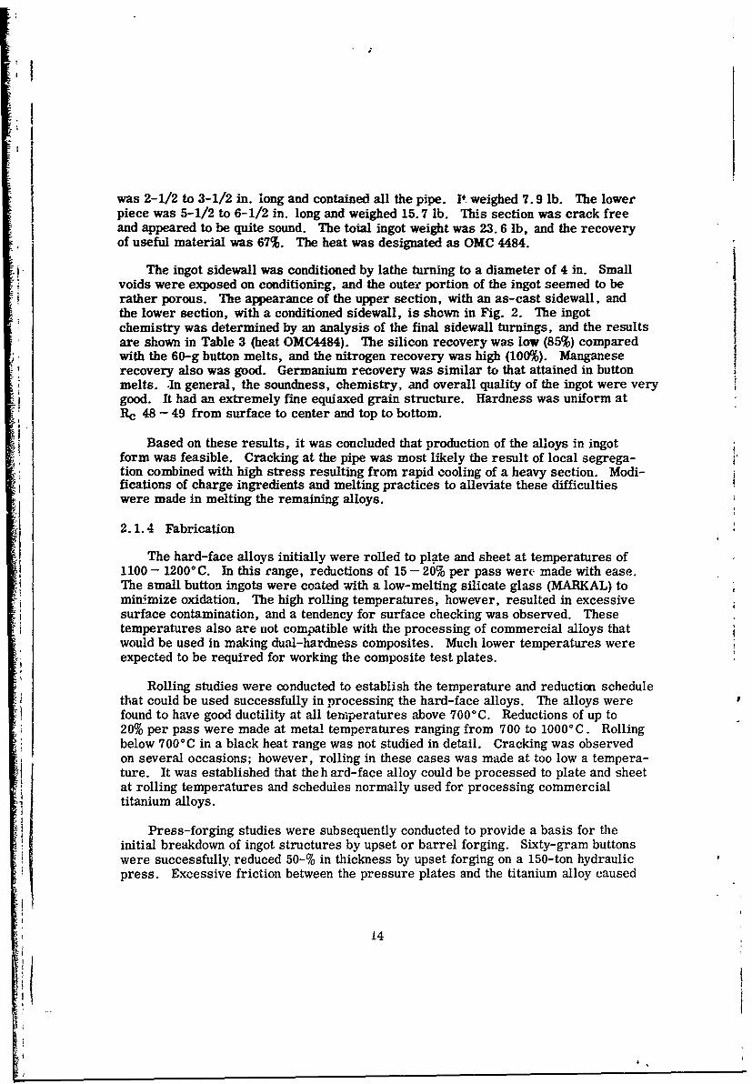
was 2-1/2 to 3-1/2 in. long and contained all the pipe. It weighed 7.9 lb. The lowerpiece was 5-1/2 to 6-1/2 in. long and weighed 15.7 lb. This section was crack freeand appeared to be quite sound. The total ingot weight was 23.6 lb, and the recoveryof useful material was 67%. The heat was designated as OMC 4484.
The ingot sidewall was conditioned by lathe turning to a diameter of 4 in. Smallvoids were exposed on conditioning, and the outer portion of the ingot seemed to berather porous. The appearance of the upper section, with an as-cast sidewall, andthe lower section, with a conditioned sidewall, is shown in Fig. 2. The ingotchemistry was determined by an analysis of the final sidewall turnings, and the resultsare shown in Table 3 (heat OMC4484). The silicon recovery was low (85%) compared
with the 60-g button melts, and the nitrogen recovery was high (100%). Manganeserecovery also was good. Germanium recovery was similar to that attained in buttonmelts. .In general, the soundness, chemistry, and overall quality of the ingot were verygood. It had an extremely fine equiaxed grain structure. Hardness was uniform atRc 48 - 49 from surface to center and top to bottom.
Based on these results, it was concluded that production of the alloys in ingotform was feasible. Cracking at the pipe was most likely the result of local segrega-tion combined with high stress resulting from rapid cooling of a heavy section. Modi-fications of charge ingredients and melting practices to alleviate these difficultieswere made in melting the remaining alloys.
2.1.4 Fabrication
The hard-face alloys initially were rolled to plate and sheet at temperatures of1100 - 12000 C. In this range, reductions of 15 - 20% per pass were made with ease.The small button ingots were coated with a low-melting silicate glass (MARKAL) tominimize oxidation. The high rolling temperatures, however, resulted in excessivesurface contamination, and a tendency for surface checking was observed. Thesetemperatures also are not compatible with the processing of commercial alloys thatwould be used in making dual-hardness composites. Much lower temperatures wereexpected to be required for working the composite test plates.
Rolling studies were conducted to establish the temperature and reduction schedulethat could be used successfully in processing the hard-face alloys. The alloys werefound to have good ductility at all temperatures above 7000C. Reductions of up to20% per pass were made at metal temperatures ranging from 700 to 10000 C. Rollingbelow 700°C in a black heat range was not studied in detail. Cracking was observedon several occasions; however, rolling in these cases was made at too low a tempera-ture. It was established that the h ard-face alloy could be processed to plate and sheetat rolling temperatures and schedules normally used for processing commercialtitanium alloys.
Press-forging studies were subsequently conducted to provide a basis for theinitial breakdown of ingot structures by upset or barrel forging. Sixty-gram buttonswere successfully, reduced 50-% in thickness by upset forging on a 150-ton hydraulicpress. Excessive friction between the pressure plates and the titanium alloy caused
14
00
cC
ooc
K:- - .
0
~to
Cd
-414
15
deep surface tears to form in all samples. This problem was solved by using fiber-glass cloth separation layers between the mating surfaces. The cloth served both toinsulate and to lubricate the composite surfaces from the pressure plates. A lowmelting (900°C) fiberglass cloth gave best results. Samples coated with fiberglasswere upset forged 50% at 1000 - l00°C without forming surface cracks or tears.The forged plates also were free of edge tears.
The use of fiberglass cloth for surface insulation and lubrication was extended torolling of the hard alloys. One layer of cloth placed on each side of a billet was fusedonto the surface in the first pass through the mill. The material remained on thesurface during all subsequent passes. Plates rolled by this practice had an excellentsurface finish. Contamination was greatly reduced, and surface tears again werevirtually eliminated.
Forging and rolling practices developed on the small button ingots were used inprocessing the large Ti-3Ge-2Si-3Mn-0. 5N alloy ingot (OMC 4484). The ingot wassectioned into two billets, each 4-in. diameter by 2-3/4-in. long. The billets were
* i coated with Markal soft glass and placed in a cold furnace. They were heated slowlyto a dull red heat (about 700'C), after which, they were transferred to a secondfurnace held at 11000 C. This procedure was used to minimize thermal gradientsthat might result in cracking. The billets were soaked one hour at 1100°C and thenpress forged to 1-3/16-in. thick plate at a load of 125 tons on a hydraulic press.Fiberglass cover sheets were used for surface insulation and lubrication. The billetswere barrel forged (axis parallel to the platens) with a total reduction of 70% inthickness. Forgeability was excellent and no edge or surface tearing occurred.
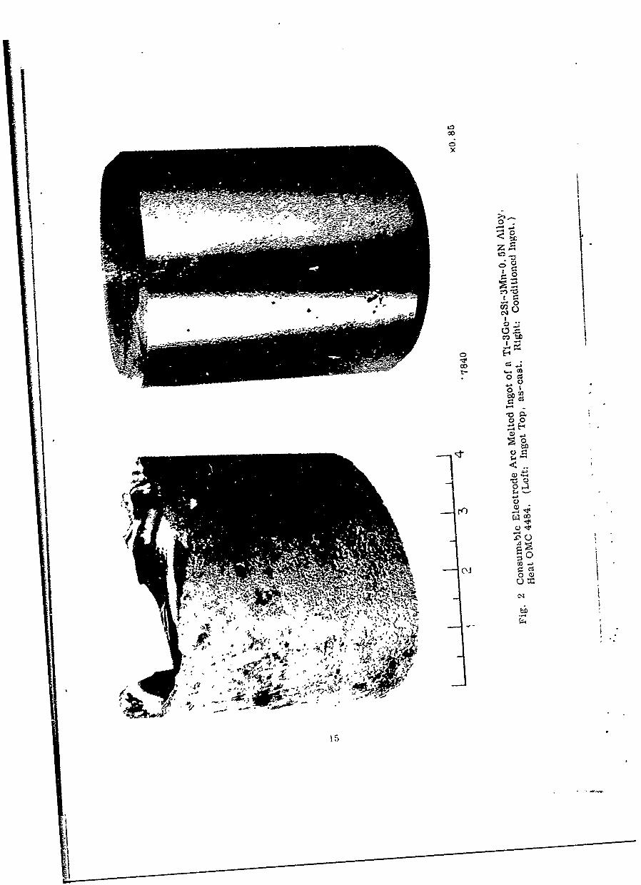
The forged plates were reheated to 1100°C and rolled to 0.83-in. thick plate ona 2-high Fenn rolling mill using reductions of 10- 15% per pass. The billets werereheated after each pass and fiberglass cover sheets were used for surface insulationand lubrication. The plates were unidirectionalty rolled to a finish size of 5 by 10 by0.83-in. After the last pass, they were reheated to 1100 0C and straightened bypressing between flat steel plates on a 125 ton hydraulic press. The finished plateswere cleaned by sand blasting. They had an excellent surface condition and werefree of edge and surface tears. The appearance of the as-roll-d plates is shown inFig. 3.
The results of these studies indicate that large ingots of the hard face alloys canbe processed to plate by forging and rolling using conventional equipment and proce-dures. The working temperature (11000C) is higher than that used in processingcommercial alloys but experience in rolling button ingots and the excellent responseof the large ingot indicate that lower temperatures most likely can be used.
2. 1. 5 Heat Treatment
Solution anneal and aging studies were conducted with sheet and plate of thecandidate hard face alloys to establish the optimum treatments. Materials preparedfrom both small button ingots and the large trial ingot (OMC 4484) were used in thesestudies. As previously mentioned, the hardness of these alloys is dependent largely on
16
0
4 0 .
vis0
C.0
t-0
17C
Ii
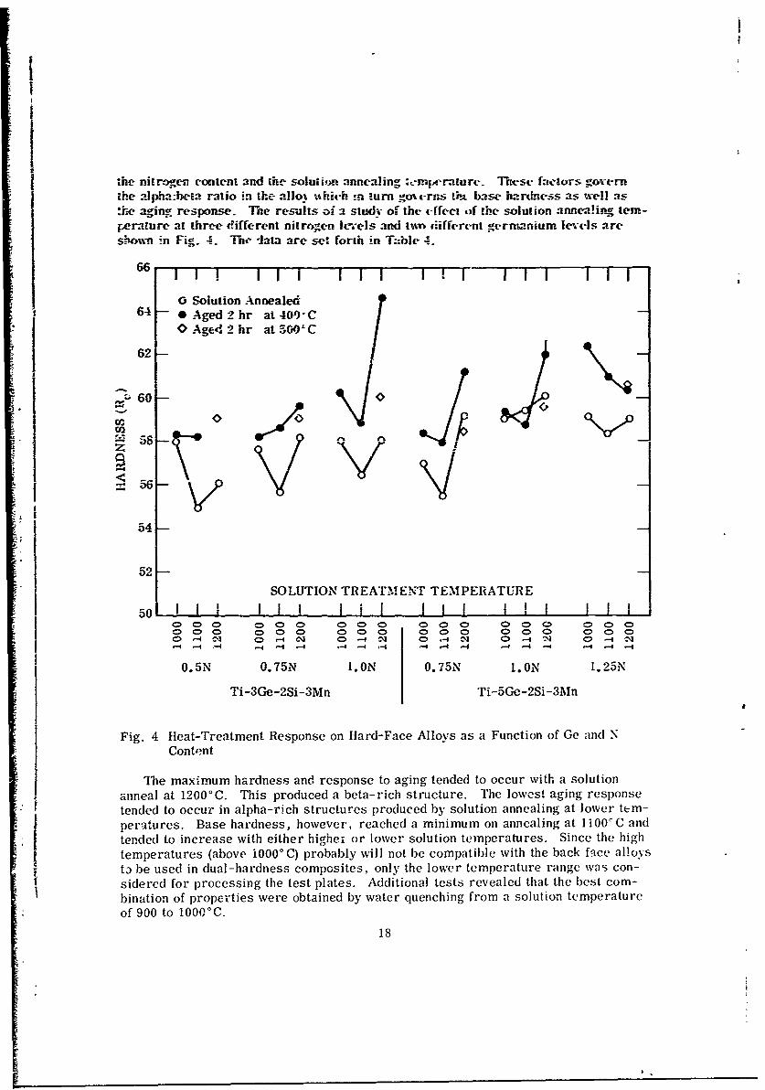
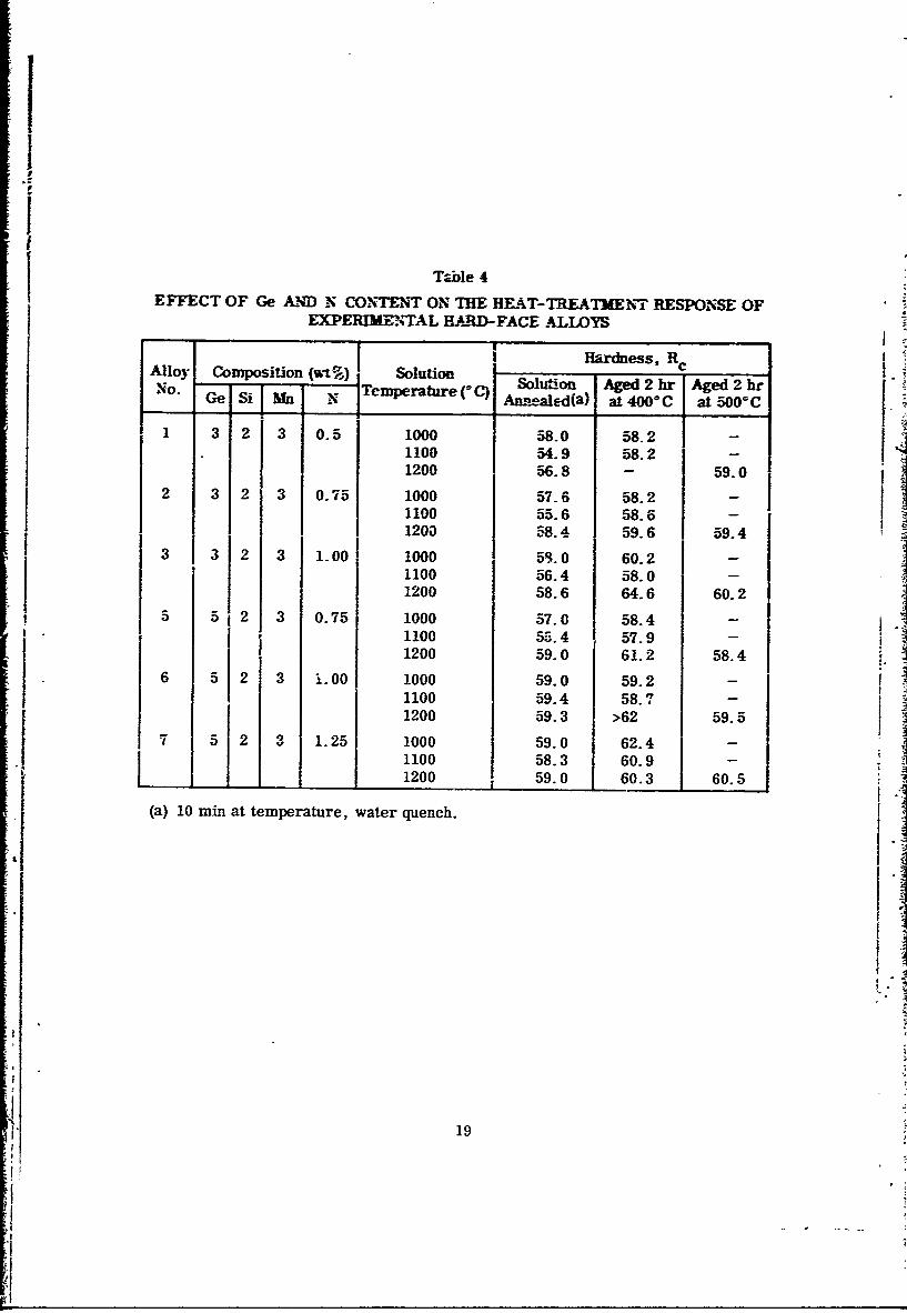
the nitrogen content and the soluaion annealing :en'mprature. TIK-se fators govern[he alpha:beta ratio in the allo. -hih n turn golt-ras lim base hardness as well as:he aging response. The results of a study of the ffec ,f the solution anne"!ing tem-perature at three different nitrogen levels and tivo diifferent gerntanium levels areshon in Fig. 4. The -lata are sef. forth in T:ble 4.
66 I1! II i II" II lIi
0 Solution Annealed64 - Aged2hr at40) -C
OAget'2hr at500'C
62-
° o"- Z 8 _V-
54
52SOLUTION TREATMENT TEMPERATURE
50 1 I I 1 1 1 1 1 1 1 1 1 1 100 0 00 0 0 000 0 0 0 00
00 000 0 0 0 0 00 0 0 0 0 00-4 ^-1 0-4 N C> 0-q W 0> -4 IN' C 0-4 3 0 -4 I-J
1-4 -4 1-4 ~ 4 -4 .- 4 .-d _4 '-f -4 ,-1 .4 -4 -4 -4 -4 -4 -4
0.5N 0.75N 1. ON 0.75N 1. ON 1. 25N
Ti-3Ge-2Si-3Mn Ti-5Ge-2Si-3Mn
Fig. 4 Heat-Treatment Response on Hard-Face Alloys as a Function of Ge and NContent
The maximum hardness and response to aging tended to occur with a solutionanneal at 12000C. This produced a beta-rich structure. The lowest aging responsetended to occur in alpha-rich structures produced by solution annealing at lower tem-peratures. Base hardness, however, reached a minimum on annealing at 1100CC andtended to increase with either higher or lower solution temperatures. Since the hightemperatures (above i000* C) probably will not be compatible with the back face alloys0 be used in dual-hardness composites, only the lower temperature range was con-
sidered for processing the test plates. Additional tests revealed that the best com-bination of properties were obtained by water quenching from a solution temperatureof 900 to 1000°C.
18
I
Table 4EFFECT OF Ge AND N CONTENT ON THE HEA-kT-TREATMEN!T RESPONSE OF
EXPERIENTAL HARD-FACE ALLOYS
Hardness, RcAlloy Composition (wt%) I SolutionA Aged 2hrNo. e S Temperature ( C) Solu~o) Aged2hr
Ge Si Mn N Annealed(a) at 400C at 50OC
1 3 2 3 0.5 1000 58.0 58.2 -
1100 54.9 58.2 -1200 56.8 - 59.0
2 3 2 3 0.75 1000 57.6 58.2 -1100 55.6 58.6 -1200 -8.4 59.6 59.4
3 3 2 3 1-00 1000 5R. 0 60.2 -
1100 56.4 58.0 -1200 58.6 64.6 60.2
5 5 2 3 0.75 1000 57.0 58.4 -
1100 55.4 57.9 -1200 59.0 61.2 58.4
6 5 2 3 IL. 00 1000 59.0 59.2 -
1100 59.4 58.71200 59.3 >62 59.5
7 5 2 3 1.25 1000 59.0 62.41100 58.3 60.9 - T
1200 59.0 60.3 60.5
(a) 10 rin at temperature, water quench.
19
II
The data shown in Fig. 4 indicate a complex interplay between composition andsolution treatment. Although the hardness changes are not l arge, the base solutionannealed hardness does increase both with increasing germanium and nitrogen content.Hardne after aging, however, largely depends on nitrogen content and the addedgm does not appear to be very effective. Detailed studies of the microstruc-Lure as influenced by compositionand heat treatment are needed to provide an under-standing of this behavior.
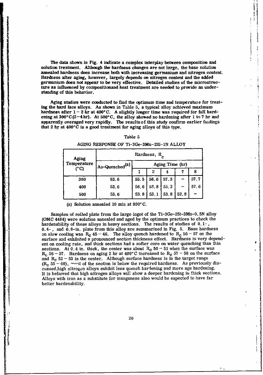
Aging studies were conducted to find the optimum time and temperature for treat-ing the hard face alloys. As shown in Table 5, a typical alloy achieved maximumhardness after 1-2 hr at 400 C. A slightly longer time was required for full hard-ening at 300*C(2-4hr). At 500 0 C, the alloy showed no hardening after 1 to 7 hr andapparently overaged very rapidly. The results of this study confirm earlier findingsthat 2 hr at 4000C is a good treatment for aging zlloys of this type.
Table 5
AGING RESPONSE OF Ti-3Ge-3Mn-2,i-1N ALLOY
Aging rHardness, RTemperature Aging Time (hr)
(CC) 1 2 4 7 8
300 53.6 55.5 56.6 57.3 - 57.7
400 53.6 56.6 5S.8 55.3 - 57.6
500 53.6 53.8 53.1 53.8 52.8 -
(a) Solution annealed 10 min at 900° C.
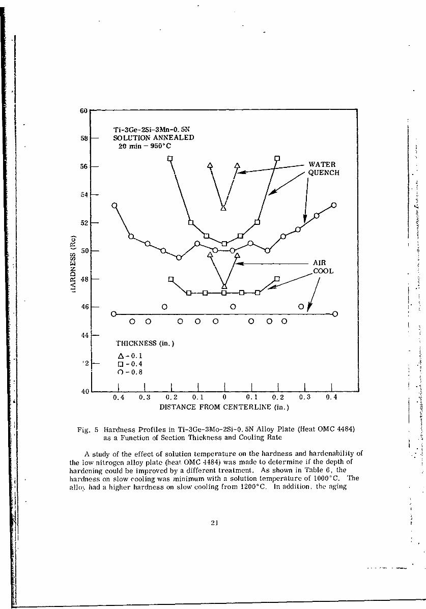
Samples of rolled plate from the large ingot of the Ti-3Ge-2Si-3Mn-0. 5N alloy(OMC 4484) were solution annealed and aged by the optimum practices to check thehardenability of these alloys in heavy sections. The results of studies of 0.1-,0.4-, and 0.8-in. plate from this alloy are summarized in Fig. 5. Base hardnesson slow cooling was Rc 45 - 46. The alloy quench hardened to Rc 56 - 57 on thesurface and exhibited a pronounced section thickness effect. Hardness is very depend-ent on cooling rate, and thick sections had a softer core on water quenching than thinsections. At 0.4 in. thick, the center was about Rc 50 - 51 when the surface wasRc 56 - 57. Hardness on aging 2 hr at 4000°C increased to Rc 57 - 58 on the surfaceand Rc 52 - 53 in the center. Although surface hardness is in the target range(Rc 55 - 60), -- ,t of the section is below the required hardness. As previously dis-cussed,high nitrogen alloys exhibit less quench hardening and more age hardening.It is believed that high nitrogen alloys will show a deeper hardening in thick sections.Alloys with iron as a substitute for manganese also woi.d be expected to have farbetter hardenability.
20
.1
I
60
Ti-3Ge- 2Si-3Mn-0.5N58- SOLUTION ANNEALED
20 min - 950'C
56 A- WATERQUENCH
52
50
4\ AIRCOOL
a 48
46 0 00 0
0 0 0 00 00 0
4 - THICKNESS (in.)
A--1f2 - [1- -0.4
0 -0.8
401 I II I I I I0.4 0.3 0.2 0.1 0 0.1 0.2 0.3 0.4
DISTANCE FROM CENTERLINE (in.)
Fig. 5 Hardness Profiles in Ti-3Ge-3Mo-2Si-O. 5N Alloy Plate (Heat OMC 4484)as a Function of Section Thickness and Cooling Rate
A study of the effect of solution temperature on the hardness and hardenability ofthe lov nitrogen alloy plate (heat OMC 4484) was made to determine if the depth ofhardening could be improved by a different treatment. As shown in Table 6, thehardness on slow cooling was minimum with a solution temperature of 1000°C. 'Me
allo% had a higher hardness on slow cooling from 12000C. In addition, the aging
21Id
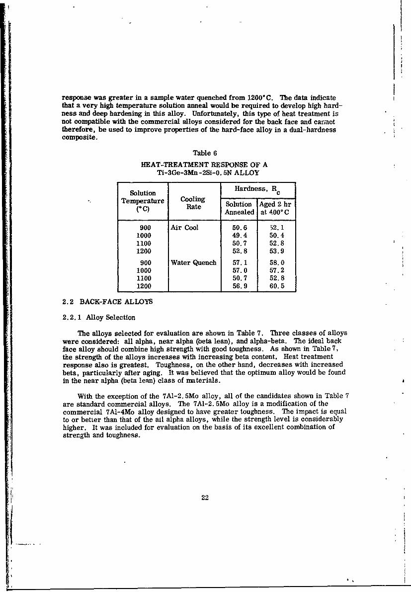
response was greater in a sample water quenched from 12000C. The data indicatethat a very high temperature solution anneal would be required to develop high hard-ness and deep hardening in this alloy. Unfortunately, this type of heat treatment isnot compatible with the commercial alloys considered for the back face and cannottherefore, be used to improve properties of the hard-face alloy in a dual-hardnesscomposite.
Table 6
HEAT-TREATMENT RESPONSE OF ATi-3Ge-3Mn-2Si-0. 5N ALLOY
Solution Hardness, RcTemperature Cooling
(C) RAnnealed at 400*C
900 Air Cool 50.6 32.11000 49.4 50.41100 50.7 52.81200 52.8 53.9
900 Water Quench 57.1 58.01000 57.0 57.21100 50.7 52.81200 56.9 60.5
2.2 BACK-FACE ALLOYS
2.2. 1 Alloy Selection
The alloys selected for evaluation are shown in Table 7. Three classes of alloyswere considered: all alpha, near alpha (beta lean), and alpha-beta. The ideal backface alloy should combine high strength with good toughness. As shown in Table 7,the strength of the alloys increases with increasing beta content. Heat treatmentresponse also is greatest. Toughness, on the other hand, decreases with increasedbeta, particularly after aging. It was believed that the optimum alloy would be foundin the near alpha (beta lean) class of materials.
With the exception of the 7A1-2. 5Mo alloy, all of the candidates shown in Table 7are standard commercial alloys. The 7A1-2. 5Mo alloy is a modification of thecommercial 7A1-4Mo alloy designed to have greater toughness. The impact is equalto or better than that of the aLl alpha alloys, while the strength level is considerablyhigher. It was included for evaluation on the basis of its excellent combination ofstrength and toughness.
22
I -
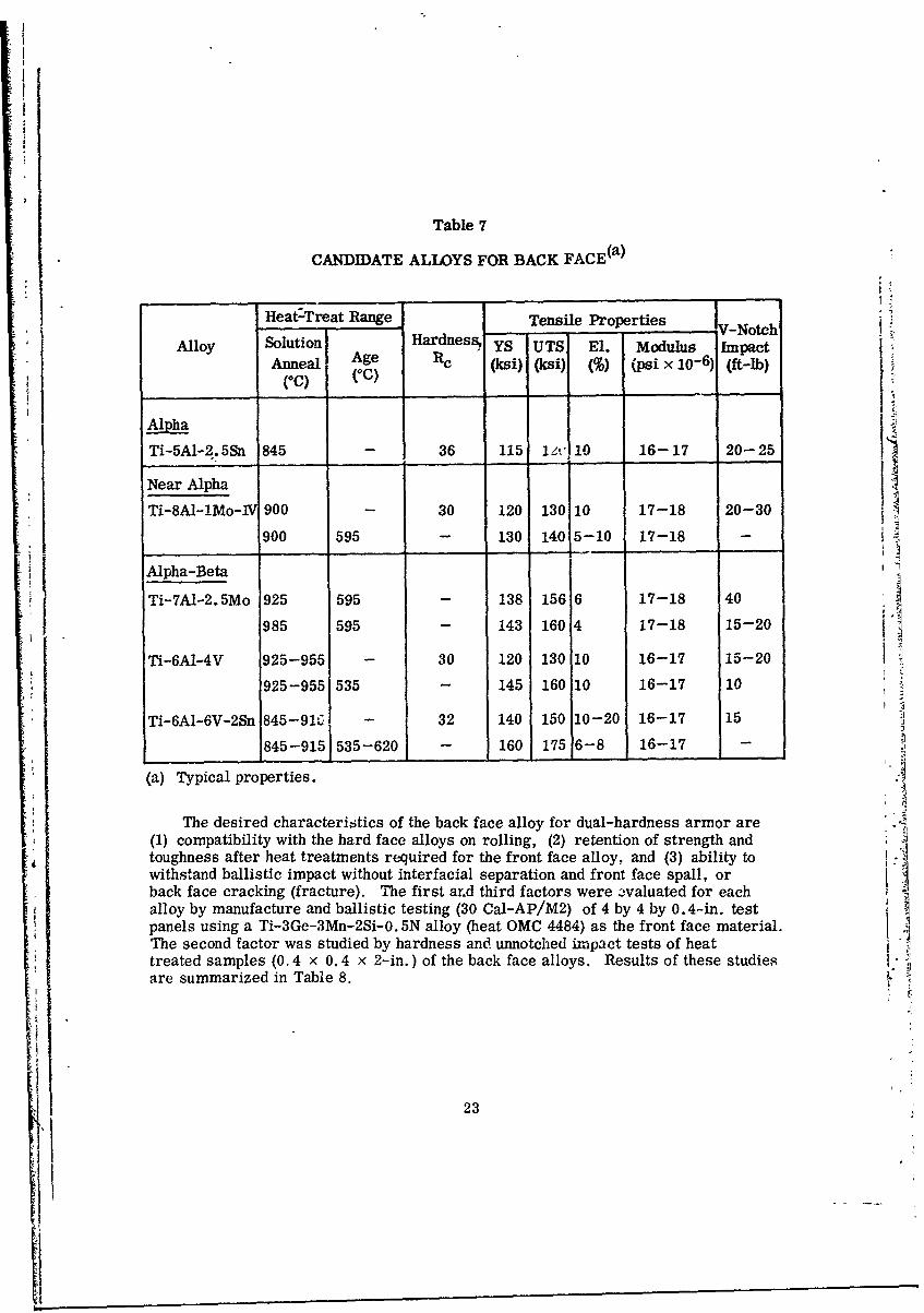
Table 7
CANDIDATE ALLOYS FOR BACK FACE(a)
Heat-Treat Range Tensile Properties V-Notch
Alloy Solutioni YS UTS El. Modulus ImpactAnneal Age Re (ksi) (ksi) (%) (psi x 10-6) (ft-lb)
(C)(C)
Ti-5A1-2.SSn 845 - 36 115 1', 110 16-17 20-25
Near Alpha
Ti-8A-lMo-IV 900 - 30 120 130 10 17-18 20-30
900 595 - 130 140 5-10 17-18 -
Alpha-Beta i-
Ti-7A1-2.5Mo 925 595 - 138 156 6 17-18 40
985 595 - 143 160 4 17-18 15-20
Ti-6A1-4V 925-955 - 30 120 130 10 16-17 15-20
925-955 535 - 145 160 10 16-17 10
Ti-6AI-6V-2Sn 845-91G - 32 140 150 10-20 16-17 15
845-915 535-620 160 175 6-8 16-17 -
(a) Typical properties.
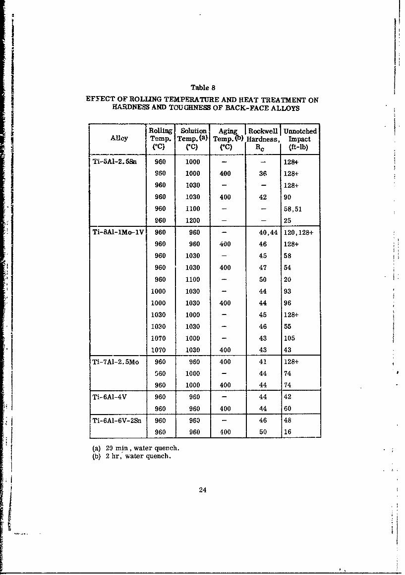
The desired characteristics of the back face alloy for dual-hardness armor are(1) compatibility with the hard face alloys on rolling, (2) retention of strength andtoughness after heat treatments required for the front face alloy, and (3) ability towithstand ballistic impact without interfacial separation and front face spall, orback face cracking (fracture). The first ar.d third factors were evaluated for eachalloy by manufacture and ballistic testing (30 Cal-AP/M2) of 4 by 4 by 0.4-in. testpanels using a Ti-3Ge-3Mn-2Si-0. 5N alloy (heat OMC 4484) as the front face material. AThe second factor was studied by hardness and unnotched impact tests of heattreated samples (0.4 x 0.4 x 2-in.) of the back face alloys. Results of these studies .are summarized in Table 8.
23
I Table 8
EFFECT OF ROLLING TEMPERATURE AND HEAT TREATMENT ONHARDNEFS AND TOUGHNESS OF BACK-FACE ALLOYS
Roling Solution IAgn Rockwell IUnnotchedI | . Temp. Temp. (a) Temp.0) Hardness, Impact
(oC) (0c) (oc) RC (ft-b)
Ti-5Al-2.5i 960 j 1000 - - 128+
960 1000 400 36 128+
960 1030 - - 128+
960 1030 400 42 90
960 1100 - - 58,51
960 1200 - - 25
Ti-8AI-lMo-IV 960 960 - 40,44 120,128+
960 960 400 46 128+
960 1030 - 45 58
960 1030 400 47 54
- 960 1100 - 50 201000 1030 - 44 93
1000 1030 400 44 96
1030 1000 - 45 128+
1 1030 1030 - 46 55
1070 1000 - 43 105
1070 1030 400 43 43
Ti-7AI-2.5Mo 960 960 400 41 128+
S60 1000 - 44 74
960 1000 400 44 74
I Ti-6A1-4V 960 960 - 44 42
960 960 400 44 60
* Ti-6A1-6V-2Sn 960 963 - 46 48
960 960 400 50 16
(a) 29 min, water quench.(b) 2 hr, water quench.
24
As anticipated, the all-alpha or beta-lean alloys had the best retention of tough-ness after solution annealing at 9600 - 10000C and aging at 4000 C. These treatmentsare designed to give optimum hardness in the front face alloy. The alpha-betaTi-7A1-2.5]Mo alloy also had-excellent toughness and was not embrittled by the 2 hrage at 4000C. The 6A1-6V-2Sn had significantly reduzed toughness after aging asa result of omega embrittlement. It can be seen from Table 8 that the solution annealtemperature is high and the aging temperature low in comparison to the normal treat-ments used for alpha-beta alloys. This can result in excessive beta formatior, graincoarsening, and beta embrittlement. The all alpha or beta lean alloys are far morecompatible with front face alloy heat treat schedules. With the exception of theTi-7A1-2. 5Mo alloy, the high strength, alpha-beta alloys lose toughness on annealingat 9600 C. The alpha or alpha-rich alloys, on the other hand, can be heated to 1030 0 Cbefore toughness begins to decrease. The higher beta transus temperature mostlikely accounts for this behavior. If these alloys are embrittled by heating to hightemperatures, toighne,.Q cannot be regained by reannealing at a lower temperature.As shown in Table 8, the Ti-8A1-1Mo-1V alloy did not regain toughness lost by heat-ing to 11000C on reheating to 960 0 C.
The results of these studies indicate that the Ti-8AI-IMo-1V and theTi-7A1-2. Mo alloys are the best candidates for the back face material. Although
j the Ti-5A1-2.5Sn alloy has good toughness and resists embrittlement, it will havea significantly lower strength for any given heat treatment. In addition to higherstrength, the other two alloys also have a higher modulus (Table 7) which is believedto be a critical factor in dual-hardness armor materials. These alloys appear tohave the best combination of strength, modulus, toughness, and latitude in processing j-for use as the back face. They can be rolled and annealed at temperatures to 1000 0Cwithout serious degradation and are most compatible with the working and annealingpractices established for the hard face alloys.
2.2.2 Composite Pr'eparation
The final selection of the back face alloy was based on an evaluation of compati-bility with the front face alloys in processing of a dual-hardness composite and onthe resistance to cracking and bond separation in ballistic impact tests. Ballistictest plates, 4 by 4 by 0.4 in., were prepared from Ti-3Ge-2Si-3Mn-0. 5N alloy plate(heat OMC 4484), and all of the candidate back face alloy plates (Table 7). The com-posites had a 50:50 ratio of hard to soft face alloys and were prepared from 0.75-in.-thick plates of each material. The plates were surface ground on each side to aid inthe formation of a uniform bond.
The initial bond between the hard and soft alloys was formed by pressure bonding -
in a vacuum hot press. Two pressure platens, each 6 in. in diameter, N'ere machinedfrom a billet of Inconel 718 alloy. The plates to be bonded were positioned between
the platens in a water-cooled stainless steel cylindrical tank that could be evacuatedto a pressure of less than 10- 5 Torr. A slurry of alumina powder in acetone wasapplied to the surface of each platen to preveiit bonding to the titanium alloy plates.
patehlb were attached to water-cooled stainless steel push rods which extended
25
Ii0
through the vacuum chamber in O-ring sealed sliding glands. A hydraulic press wasused to apply the load and a calibrated load cell was used to measure and regulatethe load.
.1 The two platens and alloy plates to be bonded were heated by induction using a10, 000 cps, 30 kW Tocco motor generator set. Temperature of the platens wasmeasured by an L&N optical pyrometer. A Pt/Pt-10 Rh thermocouple was used tomeasure the temperature of the titanium alloy plates. The couple was inserted intoa 0. 1-in.-diameter by 0. 25-in.-deep hole drilled in one side of the back-face alloy.
The bonding operation consisted of evacuating the chamber to 10- 5 Torr and heat-ing the pieces rapidly to the bonding temperature without an applied load. Normalheat up time was 30 min during which the system was thoroughly outgassed. Whenthe titanium pieces reached the desired temperature, the load was applied and steadystate conditions were held for one hour to produce the bond. The bonded pieces wereslow cooled to room temperature (about 3 hr) in a helium atmosphere before beingremoved from the chamber.
Previous work on diffusion bonding of titanium alloys at these laboratories hasshown that sound metallurgical bonds could be produced when held 1 hr at 7900 C undera load of 800 psi. Bond strength was equal to that of the base metal, and tensilecoupons containing a transverse bond failed outside the bond area. These parameterswere used in producing the dual-hardness composites. The plates were heated to760 - 7900 C and held in contact for 1 hr at a pressure of 600 - 1000 psi. The platensattained a temperature of 900 - 930* C as a result of better coupling with the inductioncoil. A sound metallurgical bond was attained as indicated by the fact that the diffu-sion bonded plates could be press forged and hot rolled in air to a total reduction inthickness of 73% without bond separation.
The pressure bonded composites were reduced 30% in thickness by press forgingfrom 10000C. The forged plates were immediately re-heated to 700, 960, or 1000'Cdepending on the back face alloy and were reduced an additional 62% in thickness byrolling. The best compatibility in forging and rolling was found for the Ti-6A1-4Valloy. There was no tendency for differential working and the finished plate retaineda 50:50 balance of hard and soft alloys. The Ti-6A1-6V-2Sn alloy was slightly weakerthan the hard face alloy during working but in general compatibility with this mate-rial also was excellent. The all alpha or alpha rich alloys were stiffer than the hardface alloy and tended to roll differentially. Lowering the working temperature to7000 C improved compatibility of the Ti-5A1-2. 5Sn alloy. The most undesirable com-patibility was found for the Ti-7A1-2.5Mo alloy rolled at 10000C. This material was
very stiff and resisted deformati.on relative to the hard alloy. The finished compositewas 29% hard face and 71% soft face as a result of the differential rolling. The datafor this study with respect to relative deformation characteristics are summarizedin Table 9.
~26
=1.0
2 -
0!. U
z 0 r.0
00p 07E
-l 04
cc -0~ 0~ 0j
cs~
--i cc .
o~~~c 0so0?0
co M
w
2 0 0
sos
to s
soo 0 0 a
50.04
cd mJ
-d I
4: < , jIr L
F- ~~F- I-F - _ _ F
27
The roll bonded composites (except E-2) were solution annealed by water quench-ing from 960 - 1000°C as sho* in Table 9. No cracking occurred. Front face hard-ness was 54 - 55 R0. The plates were aged 2 hr at 400° C, and hardness increased to56 - 57 Rc on the front face. Hardness at the interface was 52 Rc, and the back facehardness is given in Table 9. The Ti-6A1-6V-2Sn alloy was quenched from 960* Cinto iced brine (-2°C) in an effort to maximize back face toughness. The sample wasnot aged.
2.3 COMPOSITE EVALUATION
The six test plates were test fired with 30 cal AP/M2 projectiles at full load anda range of 30 ft at a Lockheed Missiles & Space Company rifle range. Velocity wasestimated to be about 2800 ft/sec. The plates were supported in a wood frame at theedges and were hit at the center with 0-deg obliquity. TLe results are summarizedin Table 9 and in Figs. 6- 8.
The worst performance was shown by composites with Ti-6AJ-4V, Ti-5A1-2.5Sn,and Ti-6Ai-6V-2Sn alloys as the back face. The first two had a bond separation onimpact and a complete front face spall. The back plates were excessively deformed.The composite with a Ti-6A1-6V-2Sn back face shattered on impact due to low tough-ness of the back face alloy. This plate, however, did fracture the projectile. Thecomposite with a Ti-8A1-lMo-IV alloy gave somewhat better results. A 2-in. -diameter arc around the impact point underwent bond separation and spalled. Thebackup plate was cracked in the plane of the sheet (delamination). The best perform-ance was exhibited by the plate with a Ti-7A1-2. 5Mo back-up, No interfacial separa-tion occurred and only a small 1-in. diameter chip spalled from the front face(Fig. 6). The back face was undeformed and no delamination in the plane of the platewas observed.
Impact bars (0.4 by 0.4 by 2) were cut from the test panels and broken by hittingthe hard face in a Manlabs compound pendulum machine. Results are summarizedin Table 9. The toughness of the composite was roughly half that of the back facealloy tested in the same manner. In all cases, cracks initiated in the hard face
alloy terminated at the bond line.
The results indicated the Ti-7A1-2.5Mo alloy to be the best backup material withthe Ti-8AI-lMo-IV alloy a second choice. The superiority of these materials isbelieved to be due to the large amount of differential working that occurs during pressforging and rolling. The bond integrity and ability to resist spall appears to increasein direct proportion to the amount of differential working that occurs. The highmodulus of these two alloys relative to other titanium alloys also may be a contribut-ing factor.
Two additional composite ballistic test panels containing a hard front face ofTi-3Ge-3Mn-2Si-0. 5N and a back face of Ti-7A1-2. 5Mo were fabricated to confirmthe results of these studies. Both composites were initially formed by diffusion bond-ing a 0. 7-in.-thick hard face plate to a 0. 6-in.-thick backup plate (54% hard) in
28
I: :
I -n
< s.
>
>-,
C,
CO
292
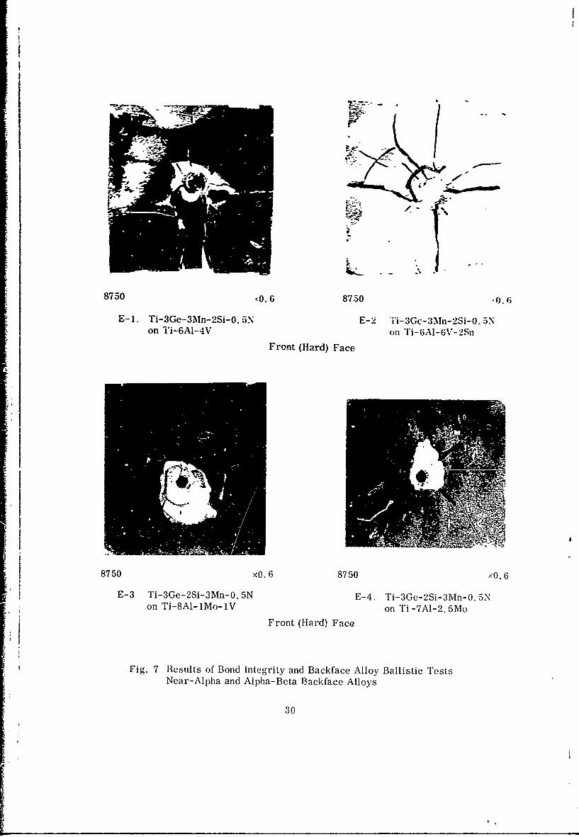
8750 -0.6 8750 06
E-1. Ti-3Ge-3M,%n-2Si-0. SN E -2 Ti-3Gc-3M_\n-2Si-O. 5\on i'i-6A1-4V on 1"i-6AI-G;V-2Sn
Front (Hard) Face
8750 xO. 6 8750 x0. 6
E-3 Ti-3Ge-2Si-3Mn-0. 5N E-4. Ti-3Ge-2S-3Mn-0. 5Non Ti-8Al1Mo-1V on Ti -7A1-2. 5Mo
.1 Front (Hard) Face
Fig. 7 Results of Bond Integrity and Backface Alloy Ballistic TrestsNear-Alpha and Alpha-Beta Backface Alloys
30
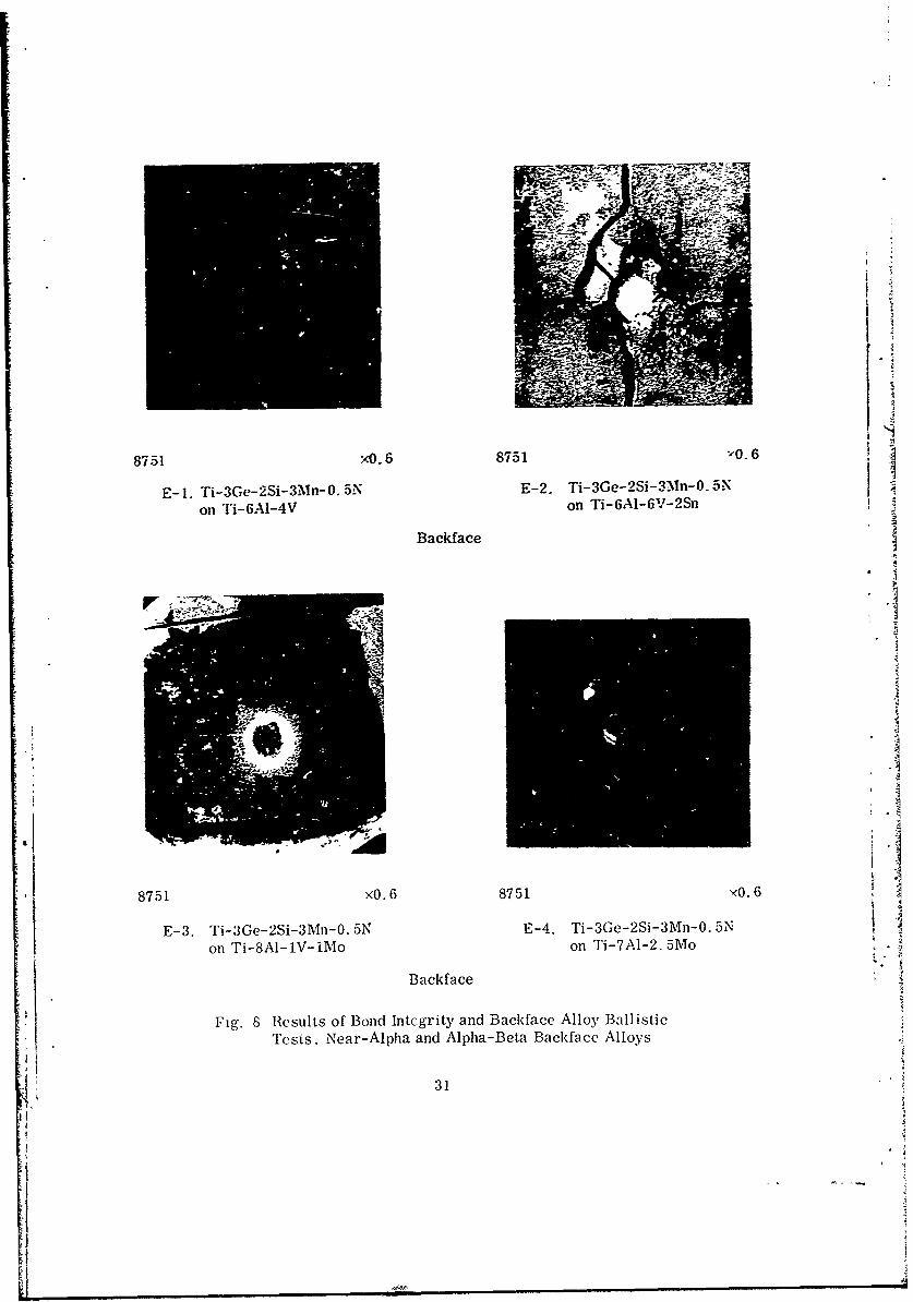
8751 X0. 6 8751 YO. 6
E-1. Ti-3G(!-2Si-3Mn-O.5N E-2. Ti-3Ge--2Si-3Mn-O. 5N
on T'i-6AI-4V on Ti-6A1-6V-2Sfl
Backf ace
8751 '.68751'06
E-3. Ti-3Ge-MS-3Mi-0. 5N E-4. Ti-3Ge-2S-3Mi-O. 5Non Tji-8A1- lV- iMo on Ti-7A1-2. SMo
Backf ace
Fig. 8 Results of Bond Intcgrity and Baekface Alloy Ballistic
Te'sts. Near-Alpha and Alpha-Beta Baekface Alloys
31
II
vacuum for 1 hr at 7800C under an applied pressure of 500 psi. Following bonding,one composite was press forged 30% at 950°C, while the other composite was pressforged a similar amount at 1050" C. Both composites were subsequently cross rolledapproramately 53% at the same temperature used for forging into 0.4-in. -thick plates.These plates were then surface conditioned to yield 4 by 4 by 0.4-in. ballistic testpanels. Based on thickness measurements, front to back face thickness ratios of0.73:1 and 1:1 were obtained in the plates rolled at 950" and 1050°C, respectively.The starting ratio was 1.17:1. The greatest anont of differential working occurredat 9500 C where the back face alloy is predominantly high strength alpha.
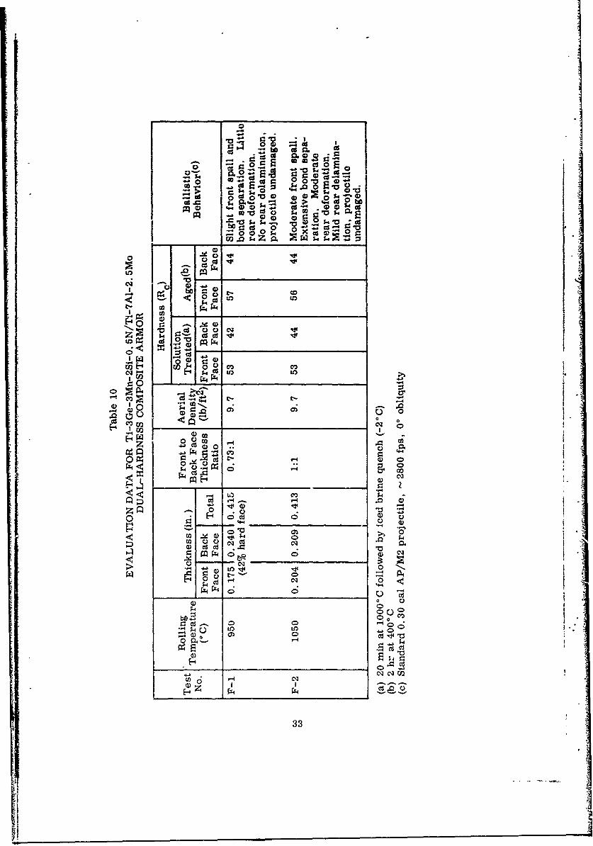
The composite panels were heat treated in accordance with practice used for thecomposite with a Ti-6A1-6V-2Sn back face to develop maximum hardness in the frontface. Heat treatment in this case consisted of solution treating 20 min at 10000C,quenching in C02 cooled brine at -2 0 C and aging 2 hr at 400°C. The front face,however, only hardened to Re 53 which is 3 - 4 points lower than expected. Theballistic tesis were conducted with the standard 0.30 cal AP/M2 projectile (i. e.,muzzle velocity of - 2800 ft/sec) at 0-deg obliquity and a range of 30 ft. Table 10summarizes the results of the rolling compatibility and ballistic evaluation studies, andcross sections of the ballistic test panels are presented in Fig. 9. For comparison, across section from a similar composite test panel containing a back face alloy ofTi-8A1-IMo-IV is also shown in Fig. 10.
The data and test panel cross sections indicate that the Ti-3Ge-3Mn-2Si-O. ZN/Ti-7A1-2. 5Mo composite which had the greatest differential working (i. e., compositeprocessed at 950°C) exhibited the best performance. The front face showed only aslight degree of spall and minor bond separation, while little or no deformation ordelamination was detected in the back face. In contrast to this behavior, the compositewith a 1:1 thickness ratio (worked from 10000C) sustained considerably more frontface spall and bond separation. Furthermore, the back face showed a slight tendencyto delaminate.
The ballistic performance of the Ti-7A1-2. 5Mo composite rolled from 9500 C alsowas superior to that for a differentially rolled composite fabricated previously with aTi-8A-lMo-IV back face alloy having the same ratio of front to rear face thickness(plate E-3). Here again, the former composite demonstrated less front face spalland bond separation and significantly less back face deformation and delamination(Fig. 10). Results of the rolling compatibility and ballistic evaluation studies con-firmed earlier findings which indicated that differential rolling enhanced bond integrityand spall resistance and that the Ti-7A1-2.5Mo back face alloy was ballisticallysuperior to the Ti-8A1-lMo-1V composition under equivalent processing and test con-ditions. No difficulty was foreseen for incorporating differential rolling into theprocessing schedule for manufacturing the final ballistic test panels. In this case,a front to back face thickness ratio of 1.5:1 was anticipated to yield a 1:1 ratio in a0. 625-in.-thick test panel following 75% reduction of the diffusion bonded compositeby forging and rolling.
32
CS C
o es 0 C
&00
4 .0 S4o 01 CIO~-
00 i.- o i '
0£
S.. r' - co
0 P0
C1
00 -4
cl0 04
0 C 0 0) 0
r- 0' * 0U24 00D~ 003
0u 0 0 4
_ _ _ _ _ _ c5 I.r.M i0 c
to .133
clH
C-
0
0
Z U)
U) o-
to io
0 O-
OD oo~ :
34 I
8801 xl. 25
E-3. Ti-3Ge-2Si-3Mn-0.5N on Ti-8L1-IMo-!V
Rolled From 950 0 C
8801 xl. 25
F-i. Ti-3Ge-2Si-3Mn-0. 5N on Ti-7AI-2, 5Mo
Rolled From 950cC
8801 xl. 25
F-2. Ti-3Ge-2Si-3Mn-0.5N on Ti-TAI-2.5Mo jRolled From 1050'C 1|
Fig. 10 Cross Section of Bond Integrity and Bachface AlloyBallistic Test Panels E-3, F-i, and F-2
35
i' 1i
I!I
Section 3
MATERIALS PREPARATION
3.1 ARD-FACE ALLOYS
Three different compositions were selected as front-face alloys ior ballistic testplates:
(1) Ti-3Ge-2Si-3Mn-O.5SN(2) Ti-5Ge-SSi-3Mn-1. ON(3> Ti-5Ge-3Si-3Fe-1. ON
* The first alloy is the composition prepared as the trial melt ingot (heat OMC 4484)for use in development studies of processing and properties. Sufficient 0.8-in.thick material remained from which to make one 6 by 6 by 0.625-in. test plate of a50:50 dual-hardness composite for final ballistic evaluation. The second and thirdalloys were selected as more promising compositions for the hard-face, and sufficientmaterial was prtepared for the manufacture of twelve 6 by 6 by 0. 625-in. ballistic testpanels.
It was planned to produce four test plates of alloy (2) in the solution annealed con-dition (Re 55 - 60) and four test plates in the fully aged condition (Rc 60 - 65). Fourtest panels also were to be produced from alloy (3) in the fully aged condition (Rc60 - 65). This material was expected to have the greatest depth of hardness.
The material selected for the back-face alloy in all 13 proposed test plates wasTi-7AI-2.5Mo. The work conducted in preparing these materials and in producingthe dual-hardness composites is described in this section of the report.
3.1.1 Melting
I The raw materials used in preparing three 25-lb ingots of the two additional hard-face alloys were sodium-reduced Ti sponge (Reactive Metals Company), electrolyt.manganese, silicon metal, Armco ingot iron, refined germanium ingot, and lumpsilicon ritri 'e. All the alloy additions were crushed to about 1/4-in. m-sh which wasthe approxir e size range of the titanium sponge. The charge weights were calcu-laid on lo, - -ecovery of all additions except for silicon from the silicon nitride.NJo allowanc- vas made for recovery of silicon from this source; consequently, eachmelt contained approximately 50 percent excess silicon.
The alloys were melted by the Oregon Metallurgical Corporation, Albany, Oregon.- The procedures used, basically, were those described in Section 2 for the prepara-
tion of the first 25-lb tr-al melt. Ai. improved hot-topping practice was employed,and the cooling waier to the cop--r mold was turned off on completion of the melt toreduce the cooling rate in an effuct to minimize ingot cracking.
36I
The first ingot to be melted was the Ti-5Ge-3Si-3Mn-1N alloy, heat OMC4599 D1. The pressed electrode was melted into a 3.5-in. diameter mold. Theingot cracked into Aght pieces on cooling. As shown in Fig. 11, the outer rim ofthe ingot was extremely porous and contained many large gas holes. Large piecesof unmelfted silicon nitride also were visible as inclusions in the ingot. The ingotpieces were subsequently tack welded together successfully and remelted in a 4. 5-in. -diameter copper mold. The second melt ingot appeared to be crack free. When the I
cutersurface was machined, however, the ingot sidewall was found to be extremely .porous.
An additional 1/2 in. was removed from the diameter by surface grinding; how-ever, the extensive porosity remained. It appeared that the porosity was very deepand that the ingot would not be suitable for processing. Consequently, the ingot wasU returned to Oregon Metallurgical Corporation for remelting.
The third melt of this ingot was made in a 6-in. --diameter mold. The ingot againcracked into several pieces on cooling. The pieces were tack welded together andremelted a fourth time in a 4. 5-in. mold. The ingot was carefully hot topped andcooled very slow vly to room temperature. it appeared to have far less porosity, andno cracks were exhibi ted on the external surfaces. The upper "piped" section wascropped off, and the remainder of the ingot was cut into two sections, each 4. 5 in.in diameter by 3 in. long. A large "center-burst" (crack) was found extending fromthe top to the bottom and from side to side in both halves. The rest of the ingotappeared to be crack free. Some porosity was still evident, but it was vory shallow(less than 0.25 in. deep). It was estimated that two to four test plates could be pre-pared from this ingot, depending upcn how the large "cenixr-burst" propagated inforging.
The second ingot io be melted was the Ti-5Ge-3Si-3Fe-1N alloy, heat OMC 4599 D2.The ingot was double vacuum arc melted using the procedures described in Section 2.During the second melt, the electrode broke and dropped into the molten pool shortlyafter the start of melting. More than a third of the ingot had to be scrapped. Theremaining sound material was side laced with unalloyed titanium for added strengthand was melted successfully into a 4. 5-in. -diameter ingot.
The surface of the ingot was found to be cracked and very porous when conditionedby 1_athe turning. The ingot was sectioned longitudinally into two halves to determinethe extent of the cracking and the porosity. Results are shown in Fig. 12. Theporosity extended to a depth of 0. 5 in. and a deep pipe extended to about one-third ofthe total ingot length. Cracks emanate transversely and diagonally from the '".-.'ped"area. Examination indicated that sufficient material might be salvaged for the manu-facture of two test plates from this alloy.
The third ingot to be melted was another heat of the Ti-5Ge-3Si-3Mn-1N alloy,heat OMC 4599 T3. The alloy was double vacuum arc melted into a 4.5-in. -diametermold by the basic practice previously described (Section 2). The second melt ingotwas found to be cracked, and a third melt was made in a 6-in. -diamneter mold. Thisingot had a deep pipe and a large centerline crack extending from top to bottom andside to side (Fig. 13). Shallow surface porosity also was in evidence.
37
Ii.
-. It 4
I A-l Al
I r 1-4
-LO
lip
'00
4-f
l)
aC)
iQ LO~C~C1
* ~ ~ S b
MI ~ -
39C).
9167
9167
Fig.13 achned ideallandxO. 67Fi.8Mined ieal n Cro)ss Section of Triple Are Mel tcdTi-Ge)Si3Mn.1N Ingot. 13eat OMIC 4,599-T3
40
The ingot was sectioned into two halves longitudinally along the centerline crack.Each half was found to be sound and free of secondary cracks. The porosity was veryshallow, and the lower two-thirds of the ingot was quite sound. The upper "piped"section was cropped off, and slifficient sound material remained for the preparation offour test plates.
The final chemical analysis of the three ingots is given in Table 3. It can be seenthat the germanium recovery was much higher than that observed in previous melts(100%), while the silicon recovery was-much lower. The actual silicon and germanium .° .residuals were very close to the desired nominal ccomposition. The residual german-ium content, however, appeared .t be much higher than that obtaiued in the buttoningots and in the first trial melt ingot. Some of these variations may be due toanalytical difficulties in determining the residual germanium. The nitrogen contentwas very close to nominal in the two manganese-bearing alloys (D1, T3) but wasabnormally high in the iron-containing alloy (D2). No explanation for this result canbe made at this time.
3.1.2 Forging
The sound pieces from each ingot were coated with Markal soft glass and heatedto 1050°C for press forging to plate. Fiberglass cloth cover sheets were used forsurface insulation and lubrication. The two pieces from heat DI (Ti-5Ge-3Si-3Mn-IN)containing the deep centerline crack were barrel forged with the crack in a verticalposition. This was done to prevent the crack from forming a flaw in the center of thefinished plate.
The upper half of the ingot which contained most of the crack, split badly on pressforging. No useful material could be salvaged for rolling to sheet. The lower haif ofthe ingot, which contained only a portion of the crack, forged well. The pieces werereduced to 2-in. -thick plate in one pressing (55% reduction). Two 3 by 3 by 2-in.pieces, which appeared suitable for further processing, were cut from the forgedplate. These pieces were used to form test plates TP-7 and TP-8.
The two halves of ingot T3 (Ti-5Ge-3Si-3Mn-1N) were barrel forged to 1. 75-in.thick plate (42% reduction). This material worked very well, and two plates of goodquality were produced. The plates were cut into four pieces, each 3 by 3 by 1.5 in.These sections were used in fabricating test plates TP-1 through TP-4.
The two ingot halves of heat T3 (Ti-5Ge-3Si-3Fe-IN) were upset forged to 1.75-in. -thick plate (45% reduction). The workability of this alloy was poor, and extensivecracking occurred. Two plates measuring 2 by 4 by 0.75 in. thick were all that couldbe gained from this heat for further processing. These plates were used to formtest plate TP-6.
The surfaces of all the forged test plates were conditioned by Blanchard grindingto remove all cracks and porosity. They were ground flat and parallel to prepare thepieces for diffusion bonding to the back-face alloy. An excellent finish was obtained
41
on all surfaces, and no problems were encountered in grinding the alloys. The edgesof all plates were conditioned by polishing on a water cooled, SiC abrasive belt.Deep cracks and porosity were conditioned locally by spot grinding. All visiblecracks and defects were removed before bonding the forged plates to the back-facealloy plates. The thicknesses of the front-face alloy pieces aftei conditioning areset forth in Table 11.
3.2 BAC'K-FACE ALLOYS
Hot-rolled plate from an experimental 1 ton heat of Ti-7A1-2. 5Mo produced forthe Lockheed Missiles & Space Company was used for the back-face alloy of each testplate. Eight pieces 4 by 4 by 1. 25 in. were cut for bonding to the hard-face alloyplates. The 4 by 4 surfaces were machined flat and parallel. The thickness of eachpiece was adjusted to the front-face alloy thickness in such a way as to provide anapproximate balance of 60% hard face and 40% soft face.
The exact thicknesses of the rear-face pieces and the front-to-rear thicknessratios are listed in Table 11. The 60:40 ratio was selected on the basis of anticipateddifferential rolling behavior of the two alloys at 950 - 1000 ° C, as discussed inSection 2. It was estimated that the hard-face alloy would deform more than thebackup alloy and that the final ratio would be 50:50 in the 0. 625 in. thick compositetest plates.
3.3 DUAL-HARDNESS TEST PLATES
3.3.1 Diffusion Bonding
The front- and rear-face alloy plates were pressure diffusion bonded using theequipment and procedures described in Section 2 of this report. The pieces werepressed between heated Inconel platens at pressures of 500 to 1000 ps'i for 1 hr attemperatures of 7500 to 8000C. The exact conditions used in bonding each compositeare summarized in Table 11. The appearance of an as-bonded alloy composite (TP-2)is shown in Fig. 14. All the pieces bonded well, and no lack of bonding at the edgeswas indicated. The back-face alloy was trimmed to conform exactly to the front-facealloy dimensions after bonding. This facilitated inspection of the bond line and pro-duced a material more suitable for forging and rolling.
The two pieces of the Ti-5Ge-3Si-3Fe-IN alloy (4599 D2) were not of sufficieixtthi-tkness to make two te.st p!ates. A double diffusion bond was made with these plaics.The two pieces were simultaneously pressure bonded to each other and to a Ti-7AI-2. 5Moback-face plate in one operLtion. The bonded composite (TP-6) contained two Dondlines, one of which was in the center of the hard-face alloy and appeared to be ofexcellent quality.
3. 3. 2 Forging and Rolling
With the exception of TP-5 (Ti-3Ge-2Si-3Mn-0. 5N), all diffusion-bonded compositeswere reduced about 40% in thickness by press forging from a temperature of 1050'C.
42

-IIC) -
S. ; a ;a
Cr to to w . w t
C; C-1- 0SnS
01
- cc C) OD C
n Q t- -
'.5 -N n n
0 P,. 0 0 0 C, -D
bel Lo OD 0- CO N 0)S
ca qcl 0 0. 0.4
En. 0- 0 Q
C12 CDSnC
V n m 0) 0 0l 0 m
r -r -' - v~' -I
EC I I I I I
0 C CE:. ~ Cs
Sn S nS
A- 7 7 7 I 43
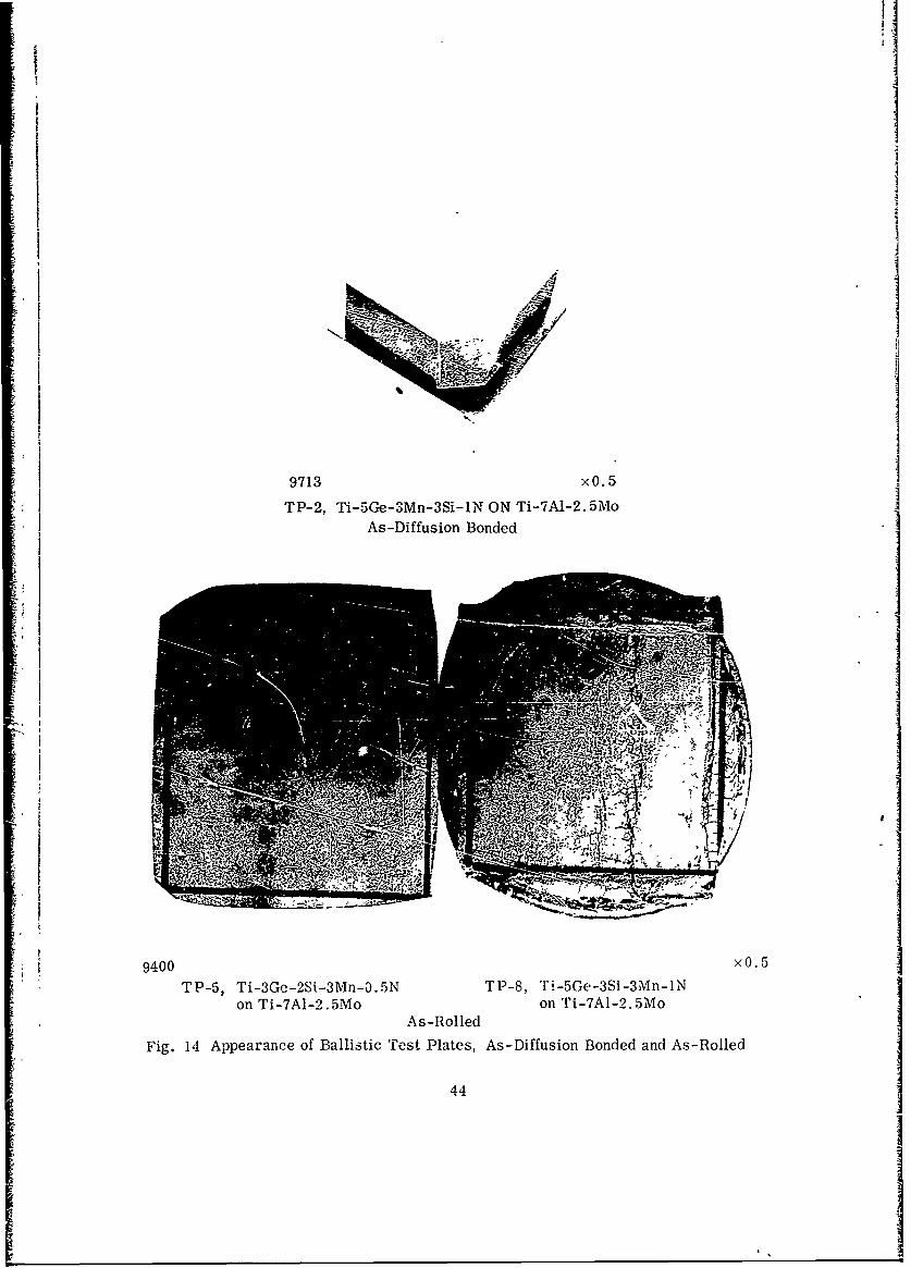
I.I
IjI
9400 xO.5
TP-5, Ti-3Ge-2Si-3Mn-0.5N TP-8, Ti-5GE-3Si-3Mn-1Non Ti-7A1-2.5Mo on Ti-7A-2.5Mo
As-Rolled
Fig. 14 Appearance of Ballistic 'rest Plates, As-Diffusion Bonded and As-Rolled
44
The final thickness of the composites and exact reductions are shown in Table 11.Composite TP-5 was not forged but was rolled directly to finished size. Fiberglasscover sheets were employed during forging for surface lubrication and heat insulationpurposes.
Composites TP-1 through TP-4 were forged between mild steel anvils. It wasfound that the anvils deformed and prevented lateral movement along the contactsurfaces. This caused rather deep surface tears to form in a square pattern thatoutlined the original shape before forging. This condition was eliminated in the threeremaining forgings (TP-6, 7,8) by the use of tungsten pressure plates. The tungstendid not deform, and the surface condition was vastly ,mproved.
In general, all the diffusion-bonded composites forged well, and no major crackingwas encountered. Composites TP-7 and 8 were found to have a poor bond along the iedges, and some bond separation occurred on deformation.
None of the alloys showed any tendency toward differential working on forging.Unlike earlier experience with the Ti-3Ge-2Si-3Mn-O. 5N alloy, the 5Ge-1N alloysused to produce these composite test plates appeared to deform to about the sameextent as the Ti-7A1-2. 5Mo backup alloy when press forged from 10500 C. As aresult, it was decided to roll from a lower temperature in order to obtain the df.er-ential working required to finish up with a 50:50 composite test plate.
All the forged composite plates were reduced 45 - 55% in thickness to 0. 650 to0. 675-in. -thick plate by rolling from 9500 C. The exact reductions and final thick-nesses are given in Table 11. Fiberglass cover sheets were again used for surfaceinsulation and lubrication during rolling. All plates were reduced to about 1. 0 in.thick by rolling in one direction, whereupon they were rotated 90 deg and finish rolledto a thickness of 0. 650 to 0. 6 15 in. The amount of cross-rolling was regulated toproduce a finished plate about 6 by 6 in. square. The plates were reheated to 9500 Cafter the last pass and straightened by pressing between steel pressure plates on a125-ton hydraulic press.
All the composite plates .end well, and no major problems were encountered.Plates TP-7 and 8 experienced further bond separation along one edge on rolling andexhibited the least desirable surface appearance of all the plates. Plate TP-5 rolledwithout the formation of any surface defects on either surface and had a surface quality Iequal to or better than that of commercial titanium alloys.
The appearance of this plate is shown in Fig. 14. The appearance of a typical Jhigh Ge, high N alloy test plate, TP-3, also is shown for comparison. Small surfacetears tended to form on the hard-face alloys during rolling. This was due to the factthat the fiberglass mats did not soften sufficiently at 950 C to provide adequate lubri-cation during rolling. Better surfaces were obtained with these alloys when a thincoating of viscous glass remained on the surface during rolling.
45II
! 4 iII
'1
Test plate TP-5 behaved exactly as expected during rolling with respect todifferential working. At 9500 C, the front-face alloy was weaker than the back-facealloy and rolled to a greater extent. As shown in Table 12 the Ainal ratio of hard tosoft alloys was 50:50 as predicted. None of the other hard-face alloys behaved inthis manner. The high Ge, high N alloys were found to have the same deformationbehavior as the back-face alloy at 9500 C. These materials either have a higher ratioof alpha to beta than the low Ge, N alloy or have a greater degree of solid solutionhardening at high temperatures. As a result, no differential rolling occurred, andthe final front to rear face ratios were about the same as the initial values (60:40).The exact values are given in Table 12.
All the test plates were cropped to 5 by 5-in. -square, and local defects wereremoved from the front and rear surfaces by belt grinding. Most of the grinding wasdone on the hard face to remove surface tears introduced in forging and rolling. Inaddition, sufficient material was remved to reduce the total thickness to 0.620 -0.635 in, (0. 625 nominal). The plates were slightly bowed in two directions andtended to be somewhat thicker in the cenvr than on the edges after grinding. The bowwas such that the hard face was slightly convex and the back face slightly concave.This is believed to be largely the result of residual stress from differential thermalexpansion of the front and rear face alloys.
3.3.3 Heat Treatment
All the test plates were solution annealed 20 min at 1000 ° C, quenched in icedbrine at -2° C, and aged 2 hr at 4000 C. The solution temperature was selected onthe basis of results of a heat-treatment study which established the optimum tempera-ture for developing the best combination of hardness and toughness in the rear facealloy (Section 2). This study was based on the use of a 0. 7-in. -thick Ti-7A1-2. 5Moback-face alloy. in fabricating the actual composite test plates, however, a differentlot of the back-face alloy measuring 1. 25 in. in thickness was employed. Consequently,before heat treating the composite test plates, sections of the thicker back-face alloywere rolled to a thickness of 0.4 in. according to the rolling schedule used in process-ing the test plates and heat treated to confirm the results of the earlier study.
As shown in Fig. 15, the unnotched impact value of the Ti-7A1-2.5Mo alloy platein die solution annealed and aged conditions did not drop significantly until the solu-tion temperature exceeded 10000 C. Hardness increased to Rc 44 - 45 in the agedcondition with a solution anneal at 1000 0C. This annealing temperature appeared toimpart the best combination of high strength (h'gh hardness) and toughness to theback-face alloy.
All the test plates were subsequently annealed succcssfully. No cracking or bondseparation occurred on quenching the large plates in iced brine from 10000C. Thebrine was cooled vrith dry ice and was agitated by CO2 bubbles. The samples werecoated with Markal glass for oxidation protection, and the quench medium had a largeanount of suspended scale and glass fragments. These fat, ork combined to producea low quenched hardness in the manganese-bearing hard-face ailoys. The hardnessvalues were 2 to 3 Rc points below anticipated values for these alloys based on priorwork. The back-face alloy hardness was exactly as expected. however.
46
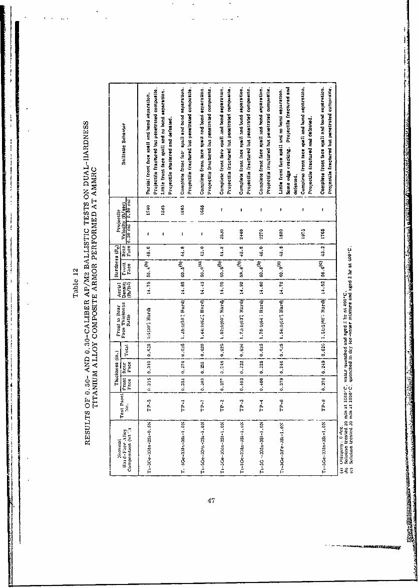
.50
0. !2 0. VE * .=[
f0
v20 - 4*0 C018
o E C5 0
00 V 0 0 0 0
to- - -0 C% -
C... - -
00
00 Z o
ID00.
V-4
00 In, 3 ~ l 0 5
P4 !S 4. z V4
Sn~~~~~ 0) 00 ) )
-n nO C") -I 3 C) "
-- 5-.~ 04 n C 0 0 0"
S .0 *' 55 0 . F'-
s.C~ ~ -, -~ ~ - -s -s471
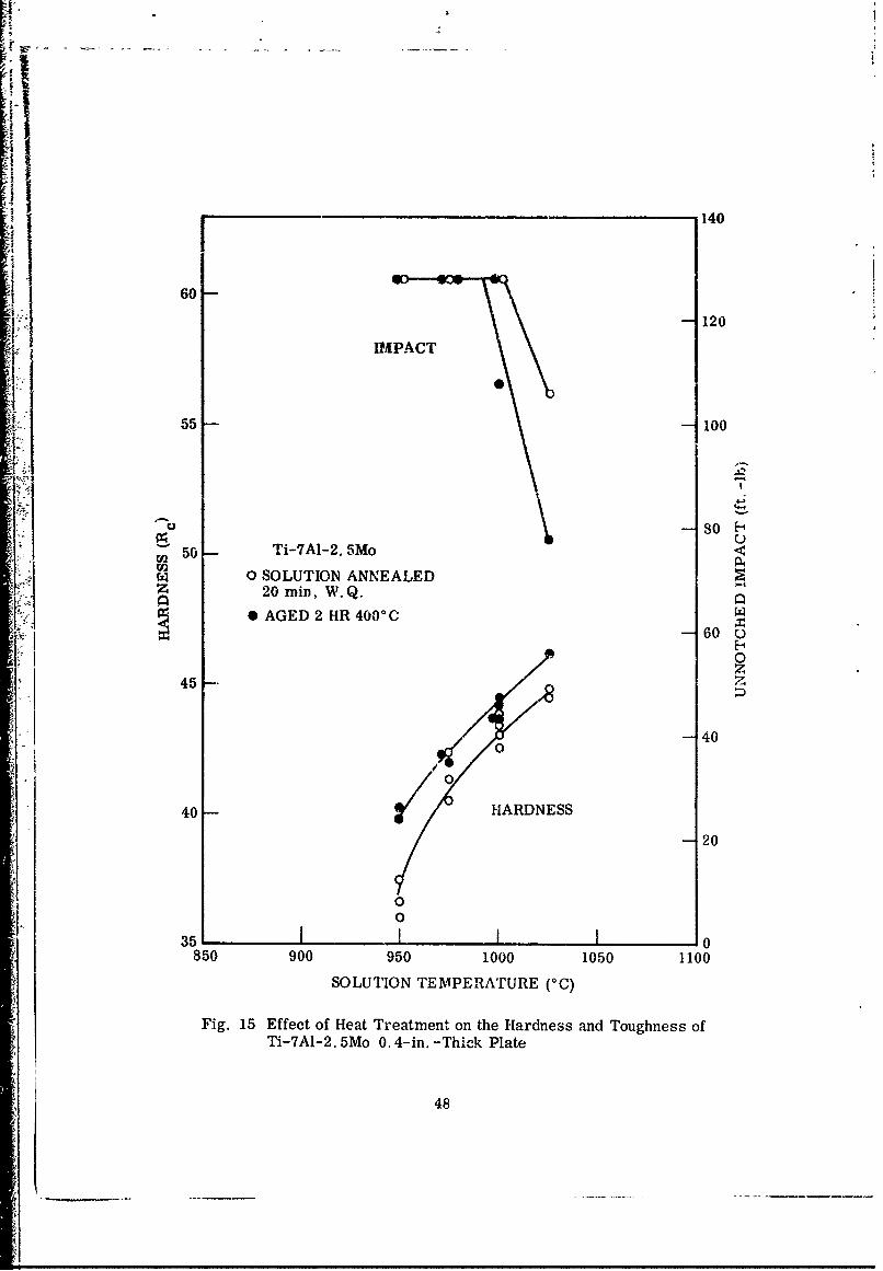
lII
r . -- o14
1 60
P 120IMPACT
55 100
soE50 - Ti-7AL-2. 5Mo
0 SOLUTION ANNEALEDz 20 min, W.Q.
*AGED 2 HR 4000 C60
/0 0z45 -.45
- -- 40
"40 - HARDNESS-- 20
/0
02
1-35 1 0850 900 950 1000 1050 1100
SOLUTION TEMPERATURE (00)
Fig. 15 Effect of Heat Treatment on the Hardness and Toughness ofTi-7A1-2. 5Mo 0. 4-in. -Thic-k Plate
48
It was postu'ated that dissolution of CO2 and suspended dirt in the quench wateras well as the Markal coat on the surface reduced the quench rate to a level consider-ably below that attained in the prior work. The iron modified alloy, TP-6, is lesssensitive to cooling rate and attained the e ,pected hardness (Rc 61) in this quenchmedium.
It was decided to reanneal the manganese-bearing alloy test plates and quenchin clean water maintained at ambient temperature. Hardness after aging (i. e., 2 hrat 400°C) increased to Rc 60 - 61 for the Ti-5G. -3Si-3Mn-1N alloys (TP-1 to 4) andto Rc 56 for the Ti-3Ge-2Si-3Mn-0. 5N alloy (TP-5). Plates TP-7 and TP-8 werenot reannealed because of the possibility that the relatively weak bond established atthe edges might have promoted complete separation on repeated thermal cycling andquenching. These plates were left at a hardness !evel of Rc 56 - 57. Their behaviorin ballistic tests, therefore, might be compared with that of a lower Ge-N alloy (TP-5)at the same hardness level. Plate TP-6 also was not reannealed, since it attainedthe expected hardness on the initial quench.
Hardness values for the front and rear faces of each test plate in the firishedcondition are presented in Table 12.
49
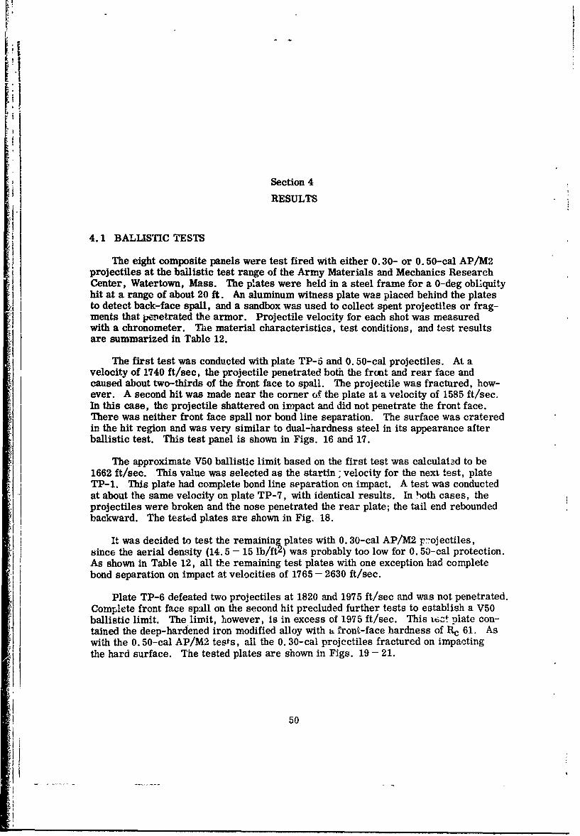
Section 4
RESULTS
4.1 BALLISTIC TESTS
The eight composite panels were test fired with either 0.30- or 0. 50-cal AP/M2projectiles at the ballistic test range of the Army Materials and Mechanics ResearchCenter, Watertown, Mass. The plates were held in a steel frame for a 0-deg obliquityhit at a range of about 20 ft. An aluminum witness plate was placed behind the platesto detect back-face spall, and a sandbox was used to collect spent projectiles or frag-ments that penetrated the armor. Projectile velocity for each shot was measuredwith a chronometer. The material characteristics, test conditions, and test resultsare summarized in Table 12.
The first test was conducted with plate TP-5 and 0.50-cal projectiles. At avelocity of 1740 ft/sec, the projectile penetrated both the front and rear face andcaused about two-thirds of the front face to spall. The projectile was fractured, how-ever. A second hit was made near the corner of the plate at a velocity of 1585 ft/sec.In this case, the projectile shattered on impact and did not penetrate the front face.There was neither front face spall nor bond line separation. The surface was crateredin the hit region and was very similar to dual-hardness steel in its appearance afterballistic test. This test panel is shown in Figs. 16 and 17.
The approximate VS0 ballistic limit based on the first test was calculatad to be1662 ft/sec. This value was selected as the startin; velocity for the next .est, plate
TP-1. This plate had complete bond line separation on impact. A test was conductedat about the same velocity on plate TP-7, with identical results. In both cases, theprojectiles were broken and the nose penetrated the rear plate; the tail end reboundedbackward. The tested plates are shown in Fig. 18.
It was decided to test the remaining plates with 0. 30-cal AP/M2 projectiles,since the aerial density (14. 5 - 15 lb/ftz) was probably too low for 0. 50-cal protection.
As shown in Table 12, all the remaining test plates with one exception had completebond separation on impact at velocities of 1765 - 2630 ft/sec.
Plate TP-6 defeated two projectiles at 1820 and 1975 ft/sec and was not penetrated.Complete front face spall on the second hit precluded further tests to establish a V50ballistic limit. The limit, however, is in excess of 1975 ft/sec. This ttz! plate con-tained the deep-hardened iron modified alloy with a front-face hardness of R 61. Aswith the 0.50-cal AP/M2 tests, all the 0. 30-cal projectiles fractured on impactingthe hard surface. The tested plates are shown in Figs. 19- 21.
50
*1
'I
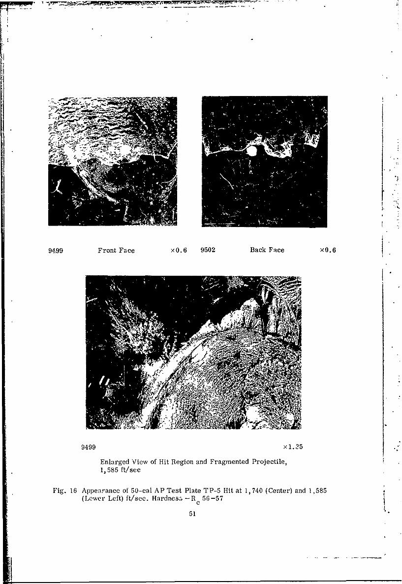
9499 Front Face xO.6 9502 Back Face xO.6
SRI.
9499 x1.35
Enlarged View of Hit Rlegion and Fragmented Projectile,
1, 585 ft/sec
Fig. 16 Appearance of 50-cal A P Test Plate T P-5 Hit at 1, 740 (Center) and 1, 585(Lower Left) ft/sec. Hardnes.- - R 56 -57
c
51
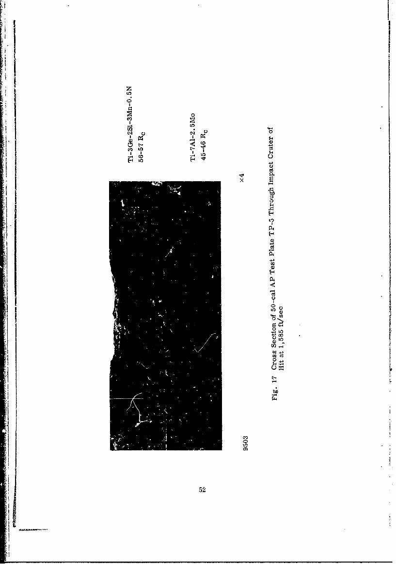
II
cli Qijto :r
-I -4
bfl0)
0 tv0
C. o
U)
D114
52
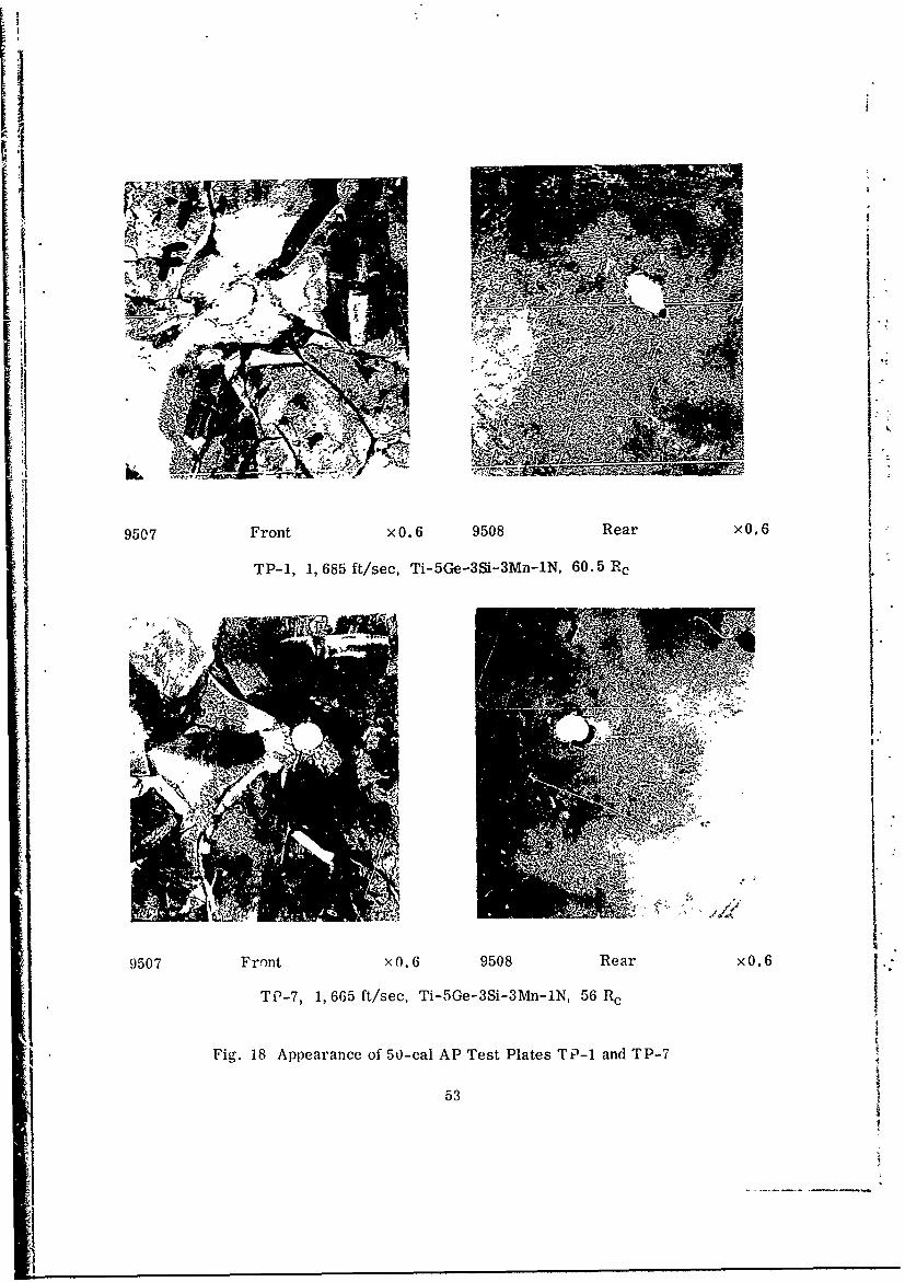
.IV
9507 Front xO. 6 9508 Rear xO. 6
TP-1, 1, 685 ft/see, Ti-5Ge-3Si-3Mn-1N, 60.5 Re
IWIM
9507 Front x0. 6 9508 Rear xO.6 VTP-7, 1, 665 ft/see, Ti-5Ge-3Si-3Mn-1N, 56 Re
Fig. 18 Appearance of 50-cal AP Test Plates TP-1 and TP-7
53
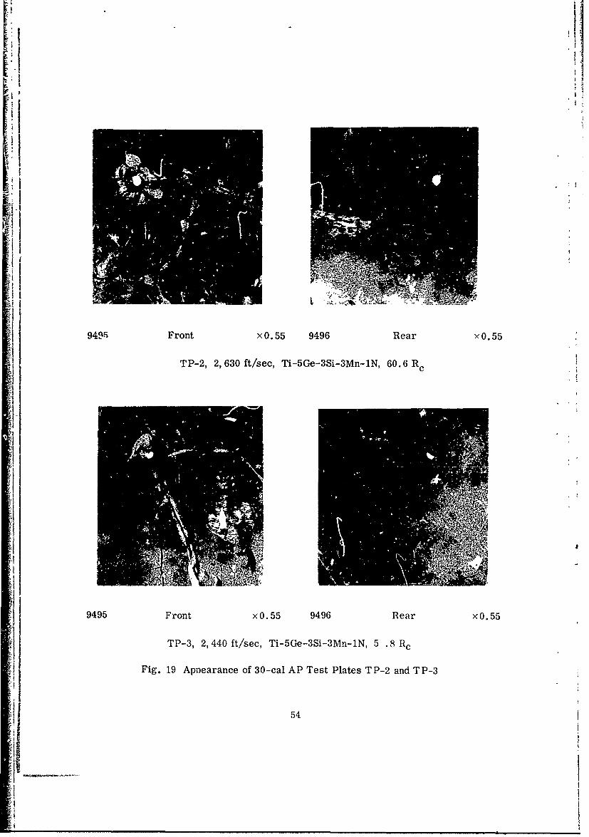
F.A,
90- Frn i. 5 99 ea .5
I9495 Front x0. 55 9496 Rear xO. 55
I TP-, 2, 60 ft/sec, Ti-5Ge-3-3Mn-MN 60.6R
Fi.111erneof3-a PTs lae P2adT-
il54
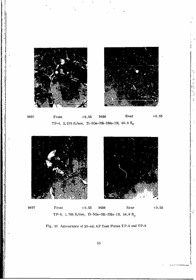
Eli
if9497 Front x0. 55 9498 Rear xO.55
TP-8, 1, 765 ft/see, Ti-5Ge-3S-3AMn-IN, 56.6 Re
iiFig. 20 Appearance of 30-cal AP Test Plates TP-4 and TP-8
551
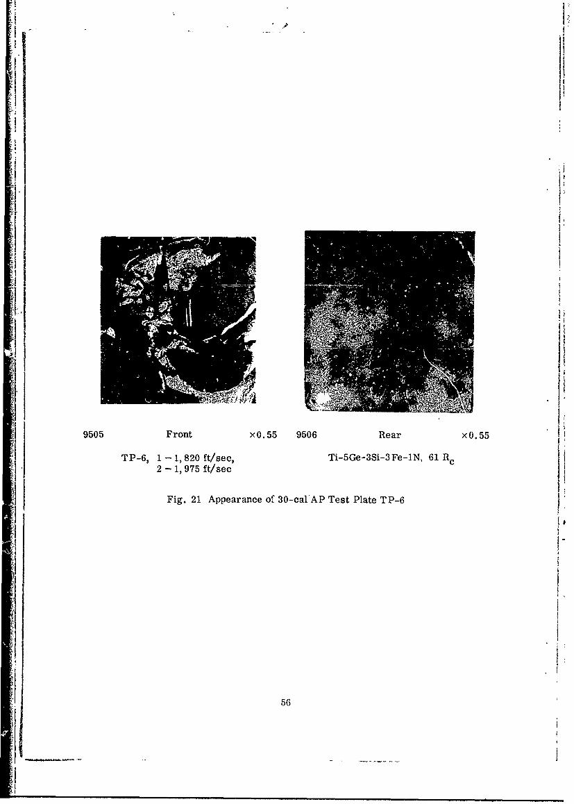
2 - 1 975 t/se
Fig 21Apaac1f!-alA etPaeT-
- 56
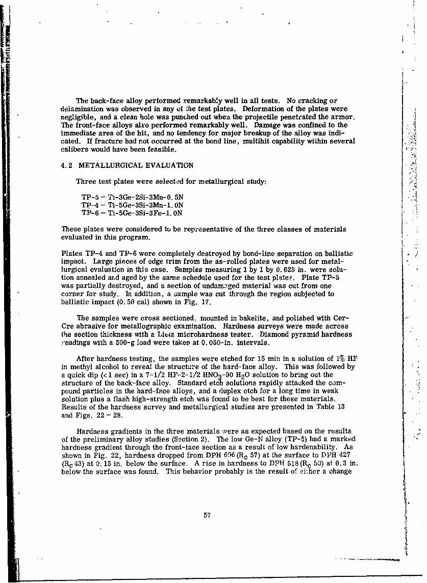
The back-face alloy performed remarkably well in all tests. No cracking ordelamination was observed in any f !he test plates. Deformation of the plates werenegligible, and a clean hole was punched out when the projectile penetrated the armor.The front-face alloys al.,:o performed remarkably well. Damage was confined to the
immediate area of the hit, and no tendency for major breakup of the alloy was indi-cated. If fracture had not occurred at the bond line, multihit capability within severalcalibers would have been feasible.
4.2 METALLURGICAL EVALUATION
Three test plates were selected for metallurgical study:
TP-5 - Ti-3Ge-2Si-3Mn-O. 5NTP-4 - Ti-5Ge-3Si-3Mn-1. ONTP-6 - Ti-5Ge-3Si-3Fe-1. ON
These plates were considered to be representative of the three classes of materials
evaluated in this program.
Plates TP-4 and TP-6 were completely destroyed by bond-line separation on ballisticimpact. Large pieces of edge trim from the as-rolled plates were used for metal- Klurgical evaluation in this case. Samples measuring 1 by 1 by 0. 625 in. were solu-tion annealed arid aged by the same schedule used for the test plate-. Plate TP-5was partially destroyed, and a section of undamaged material was cut from onecorner for study. In addition, a sample was cut through the region subjected toballistic impact (0. 50 cal) shown in Fig. 17.
The samples were cross sectioned, mounted in bakelite, and polished with Cer-Cre abrasive for metallographic examination. Hardness surveys were made acressthe section thickness with a Liecz microhardness tester. Diamond pyramid hardnessreadings with a 500-g load were takern at 0. 050-in. intervals.
After hardness testing, the samples were etched for 15 min in a solution of 1% HFin methyl alcohol to reveal the structure of the hard-face alloy. This was followed bya quick dip (< 1 see) in a 7-1/2 HF-2-1/2 HNO -90 H2 0 solution to bring out thestructure of the back-face alloy. Standard etch solutions rapidly attacked the com-pound particles in the hard-face alloys, and a duplex etch for a long time in weaksolution plus a flash high-strength etch was found to be best for these materials.Results of the hardness survey and metallurgical studies are presented in Table 13and Figs. 22 - 28.
Hardness gradients in the three materials were as expected based on the resultsof the preliminary alloy studies (Section 2). The low Ge-N alloy (TP-5) had a markedhardness gradient through the front-lace section as a result of low hardenability. Asshown in Fig. 22, hardness dropped from DPH 606 (Rc 57) at the surface to DPH 427(Rc 43) at 0.15 in. below the surface. A rise in hardness to DPH 518 (Rc 50) at 0.3 in.below the surface was found. This behavior probably is the result of ei.her a change
57
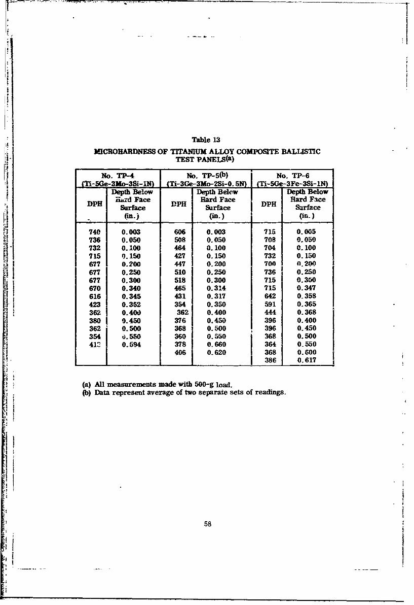
N N
j Table 13
I MCROHARDNESS OF TITAIUUM ALLOY COMPOSITE BALUiSTiCI - TESTr PANEIS(a)
No. TPX-4 No. TP-5(b) [ No. TP-6
TI-Ge-3Mo-3Si-, (-3e-3Mo-Si-0.5N) (Ti-SGe-3Fe-3Si-IN)Depth Below Depth Belew Depth BelowHd Face Hard Face Hard Face
DPI Surface DP Surface H Sface
(in.) (in.) (in.)
740 0.003 606 0.003 715 0.005736 0.050 508 0.050 708 0.050732 0.100 464 0.100 704 0.100715 0.150 427 0.150 732 0150677 0.200 447 0.200 700 0.200
1 677 0.250 510 0.250 736 0.250677 0.300 518 0.300 715 0.300670 0.340 465 0.314 715 0.347616 0.345 431 0.317 642 0.358423 0.352 354 0.350 591 0.36536 0.4O 36 0.400 444 0.368380 0.450 376 0.450 396 0.400
362 0. 500 368 0. 500 396 0.450: 354 f). 550 360 0. 550 368 0. 500
41C 0.594 378 0.660 364 0.550
406 0.620 368 0.600___386 0.617
(a) All measurements made with 500-g load.(b) Data represent average of two separate sets of readings.
I5i
I
*1I
58
:14'
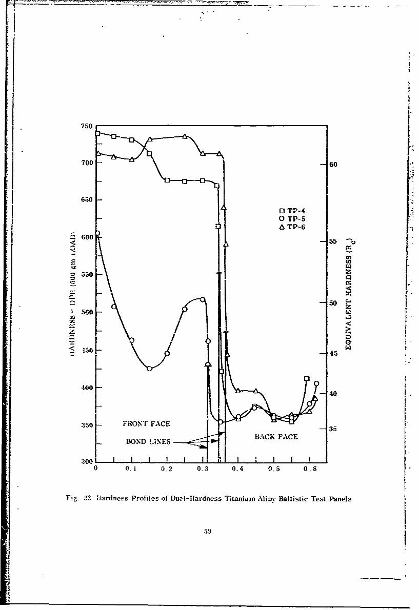
[%
750
700 0 60
650
0 TP-40 TP-5A TP-6
600 .< ~-55
00U,
550 z:
~ ~5050
45
40O0--40
- V
350 FRONT FACE 35
L1NES BACK FACE
300,
0 .1 0.2 0.3 0-4 0.5 0.6
Fig. 22 Hardness Profiles of Du2l-lardness Titanium Alioy Ballistic Test Panels
595
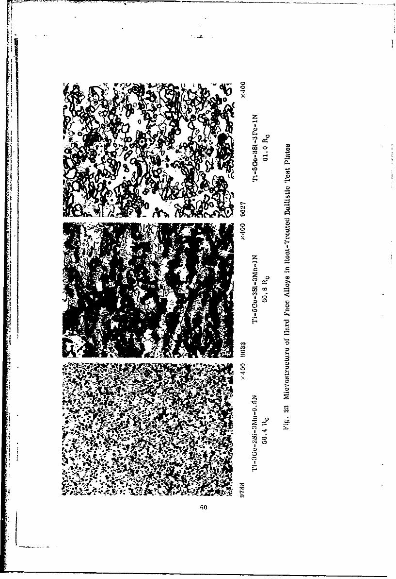
1II
-II
-IE
-fZ
-1o
-;IEli .)4inIEZe4
Ir -
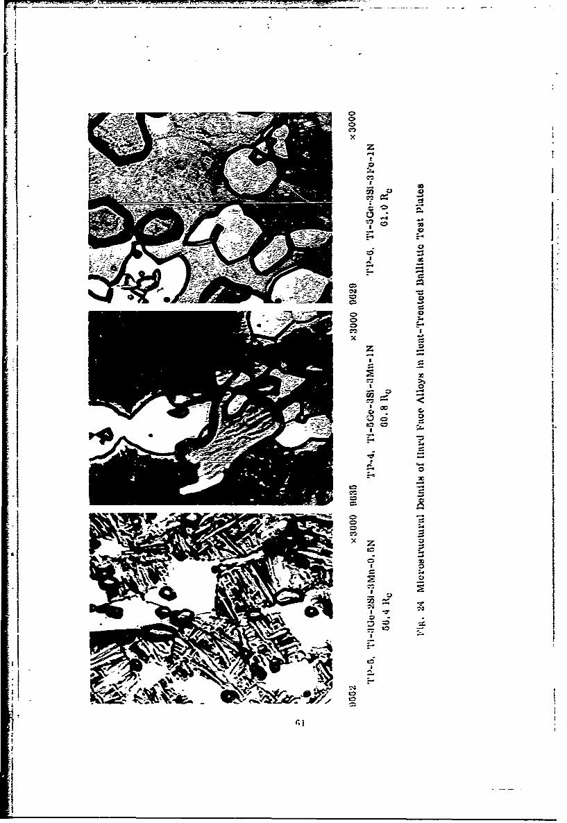
F -__ __
II
a I- a [
.1 I:0
I x -
I I.1 ~ I III
I-4
'I IIa
* 0
aI -
4
I
I
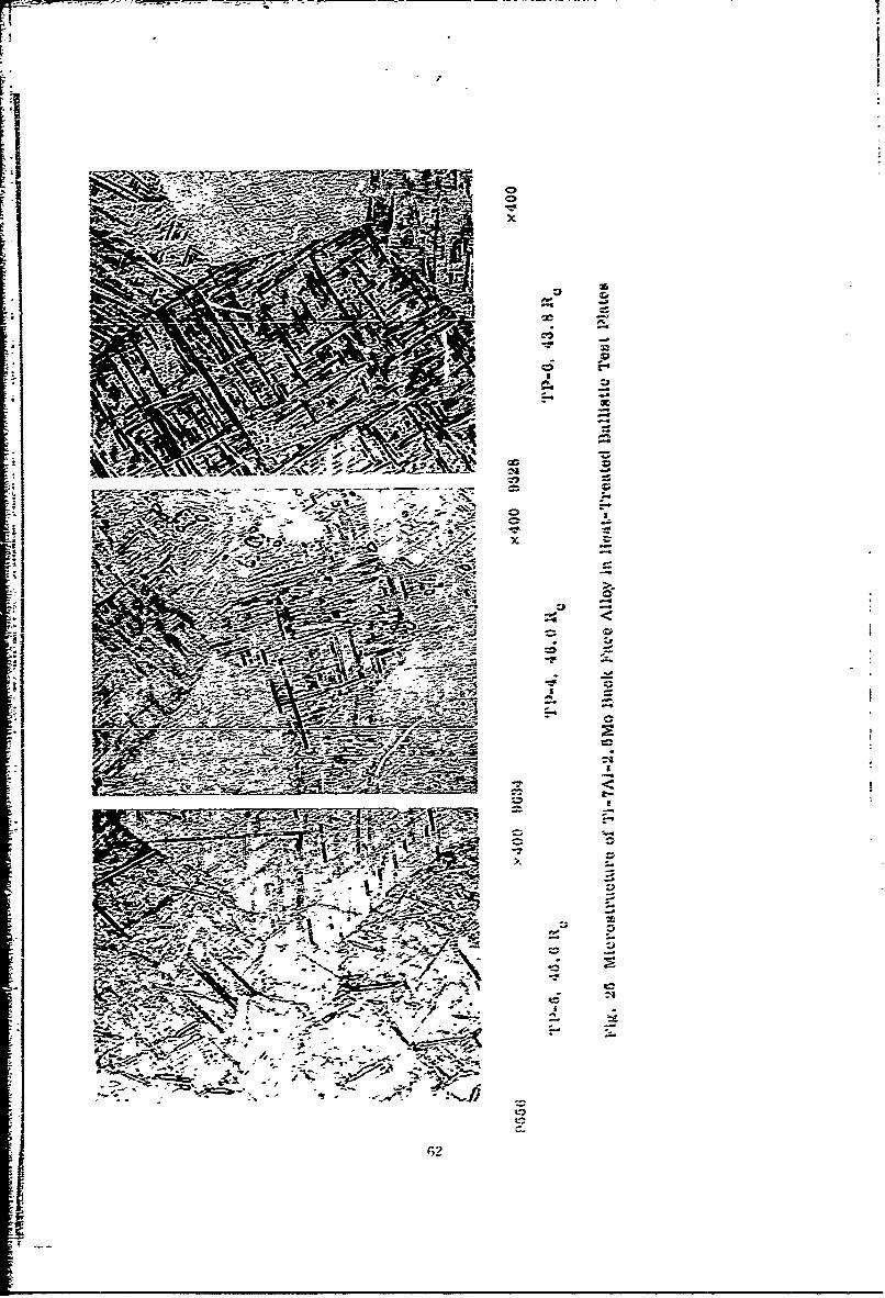
wr
Wiml'
~~;- -* A -
At
62D
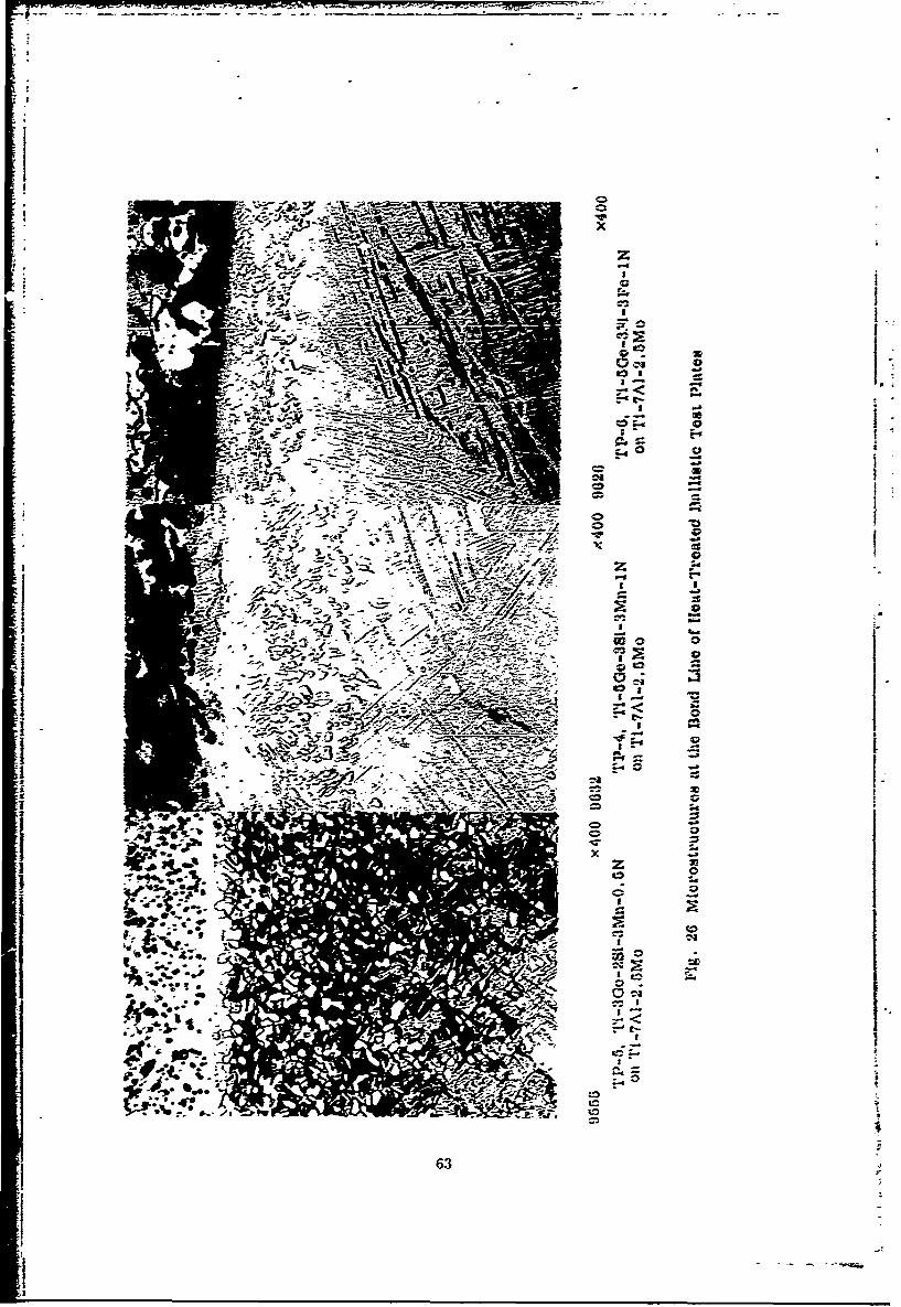
p.4
-0 C;
S .- -
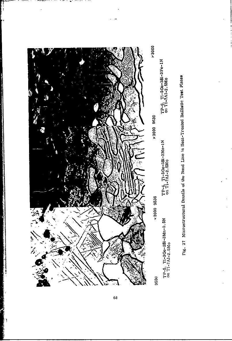
.1v
C-1~
IF-
V-3
9 1 to--' 0-
A6
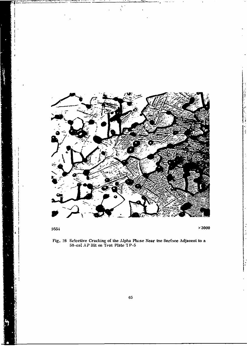
5 -c APHtoiettit -
-'--c i65
in alloy comr.osition due to the diffusion of nitrogen into the back-face alloy or theexistence of a cntical cooling rate with respect to hardening in this alloy. The exactcause of this unusual behavior was not established, however.
The two high Ge-N alloys had much better hardenability. The Mn-bearing alloy(TP-4) had a _lightdrop in hardness from DPH740 (Rc 62) at the surface to DPH 677(Rc 59) at 0. 2 in. below the surface. As expected, the Fe-bearing alloy (TP-6) hadthe best hardenability with virtually no hardness gradient from the surface to the bondline. Hardness through the front face varied from DPH 700to 736(R c CO-61). Themeasured DPH values for the front-face alloys correlated very well with measuredRc hardness values based on conversion tables derived for high-hardness steel.
A very pronounced drop in hardness occurred across the bond line for all testplates, ps shown in Fig. 22. This behavior is ideal for a dual -hardness armor. Theback-fa&e alloy hardness tended to be uniform. A slight increase in hardness wasobserved at the outer (back) surface. This may be a hardenability effect or may bethe result of interstitial contamination during processing. No major hardening as aresult of nitrogen diffusion across the interface from the hard-face alloy is indicated.The DPH measurements on the back-face alloy indicate a lower Re value from hard-ness coversion tables than the measured Rc values.
The general microstructure of the three front-face alloys is shown in Figs. 23and 24. The ailqys have about a 1:1 ratio of alpha Lnd alpha prime (martensite) asa fine grained, .Auiaxed structure. The martensite in the Fe-modified alloy (TP-6)is submicroscopic and x-ray diffraction studies revealed that none of the three alloyscontained retained beta. The third phase (dark etching) in all alloys is a Ti-Ge-Siconmound. It appears in a random distribution, with a tendency to occur at theboundaries between the alpha and alpla prime (martensite) grains. The presence ofthis phase is believed to be responsible for the fine grain size retainud in these alloysafter high-temperature working and annealing.
The most significant difference in structure between the three alloys is the ultra-fine grain size exhibited by plate TP-5. The compound particles are much smallerin this alloy as a result of its low Ge (3%) and Si (2%) contents. The alloys with5Ge-3Si contain large particles of the compound and have a much coarser grain struc-trge. These differences indieate that a lower total Ge-Si content may be preferablej for optimum refinemenn ,A *.e microstructure.
1! *1The most significant structural feature of all the alloys is the fact that none of
the three phases form a continuous hard, brittle network. The martensite phaseappears to be the matrix phase and has the greatest continuity. Previous workrevealed that this phase has a hardness of about 680 DPH in heat-treated alloys of thiscJass. The alpha phase, on the other hand, has a hardness of about 900 DPH. It isbelisved that the overall hardness and toughness is largely controlled by the proper-tics of the martensitic matrix phase.
I
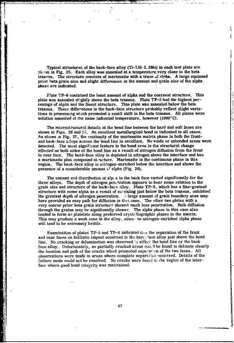
Typical structures of the back-face alloy (Ti-TAI-2. 5Mo) in each test plate aresh:E:'cn m Fig. 25. Each alloy was annealed at a temperature.very close to the betaransus. The structure consists of martensite with a trace of Rnha. A large equiaxed
prior beta grain size and slight differences in the amount and grain size of the alphapha&, are indicated.
Plate TP-6 contained the least amount of alpha and the coarsest structure. Thisplate was annealed slghtly above the beta transus. Plate TP-5 had the highest per-centage of alpha and the finest structure. This plate was annealed below the beta
transus. These differences in the back-face structure probably reflect slight varia-tions in processtng wI-ach promoted a small shift in the beta transus. All plates weresolution annealed at the same indicated temperature, however (10000C).
The microstructur.al details at the bond line between the hard and soft faces areshown in Figs. 26 and 2i. An excellent metallurgical bond is indicated in all cases.As shown in Fig. 27, the continuity of the martensite matrix phase in both the front-and back-face a2loys across the bond line is excellent. No voids or unbonded areas weredetected. The most significant feature in the bond area is the structural changeeffected on both sides of the bond line as a result of nitrogen diffusion from the frontto rear face. The hard-face alloy is depleted in nitrogen above the interface and hasa martensite plus compound st.'cture. Martensite is the continuous phase in thisregion. The back-face alloy is nitrogen-enriched below the interface and shows thepresence of a considerable amount fr alpha (Fig. 26).
The amount and distribution of alp. a in the back face varied significantly for thethree alloys. The depth of nitrogen peurtration appears to bear some relation to thegrain size and structure of the back-face alloy. Plate TP-5, which has a fine-grainedstructure with some alpha as a result of a,,ealing just below the beta transus, exhibitedthe greatest depth of nitrogen penetration. ,'% large amount of grain boundary area mayhave provided an easy path for diffusion in tbi case. The other two plates with avery coarse prior beta grain structure showed much less penetration. Bulk diffusionthrough the grains may be significantly slower. The alpha phase in this case alsotended to form as platelets along preferred cryst-Uographic planes in the matrix.This may produce a weak zone in the alloy, since '.he nitrogen-enriched alpha phasewill tend to be extremely brittle.
Examination of plates TP-5 and TP-6 indicated t k ,L the separation of the frontand rear faces on ballistic impact occurred in the, harc - ace alloy just above the bondline. No cracking or delamination was observed *,i eithe! the bond line or the backface alloy. Unfortumately, no partially cracked areas cov, I be found to delinate clearlythe location and path of the cracks which promoted sepa'-a 'on of the two faces. Allobservations were made in areas where complete separat occurred. Details of thefailure mode could net be resolved. No cracks were foui, it. ihe region of the inter-face where good bond integrity was maintained.
67
........
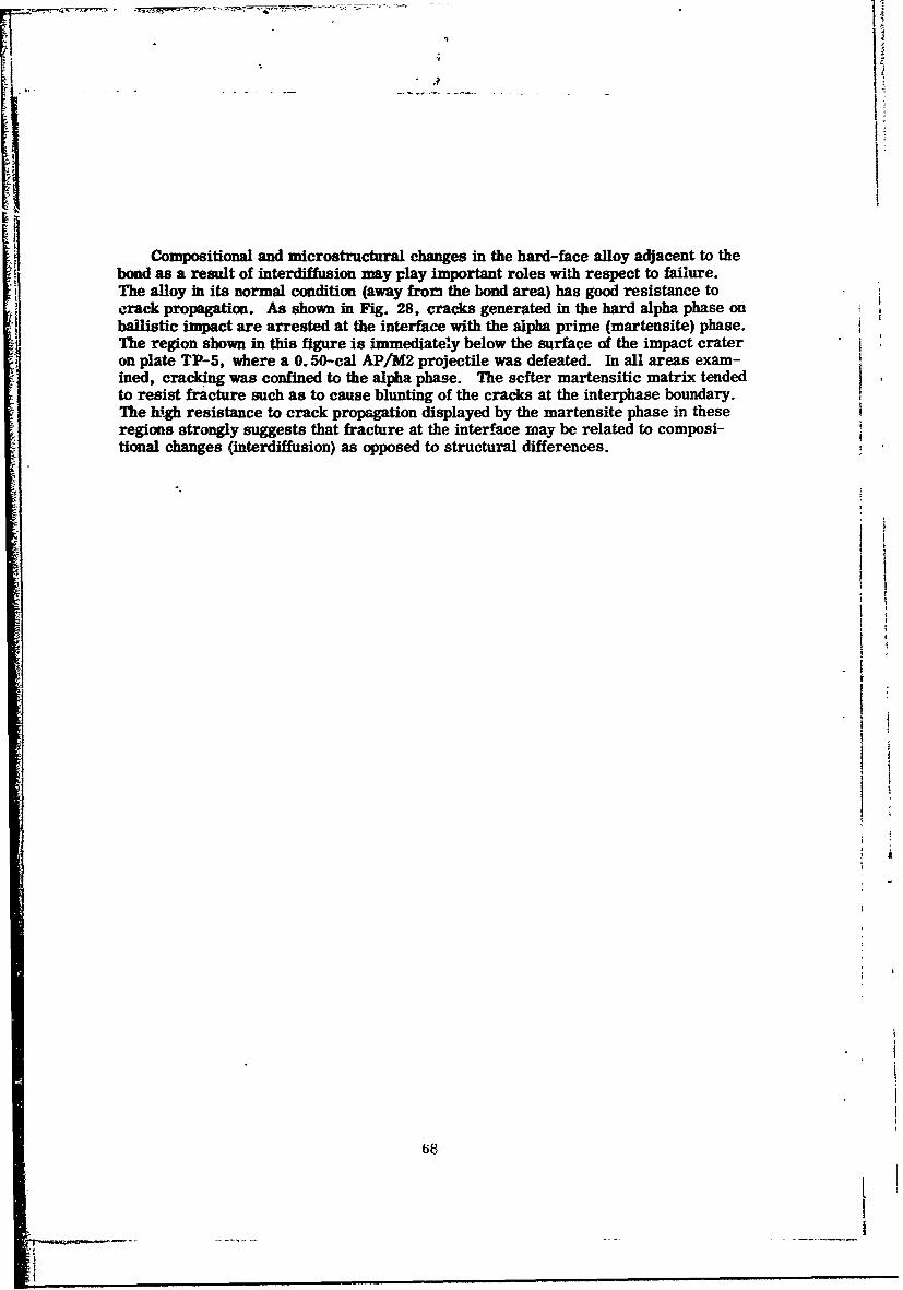
Compositional and microstructural changes in the hard-face alloy adjacent to thebond as a result of interdiffusion may play important roles with respect to failure.The alloy in its normal condition (away fron the bond area) has good resistance tocrack propagation. As shown in Fig. 28, cracks generated in the hard alpha phase onballistic impact are arrested at the interface with the alpha prime (martensite) phase.The region shown in this figure is immediately below the surface of the impact crateron plate TP-5, where a 0.50-cal AP/M2 projectile was defeated. In all areas exam-ined, cracking was confined to the alpha phase. The softer martensitic matrix tended Ito resist fracture such as to cause blunting of the cracks at the interphase boundary.The high resistance to crack propagation displayed by the martensite phase in theseregions strongly suggests that fracture at the interface may be related to composi-tional changes (interdiffusion) as opposed to structural differences.
o.1
68
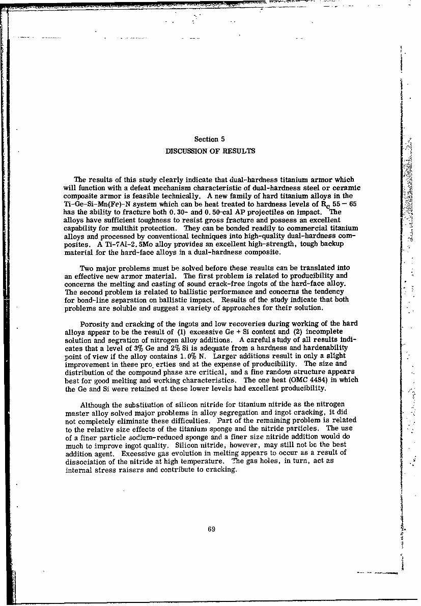
Section 5
DISCUSSION OF RESULTS
The results of this study clearly indicate that dual-hardness titanium armor whichwill function with a defeat mechanism characteristic of dual-hardness steel or ceramiccomposite armor is feasible technically. A new family of hard titanium alloys in theTi-Ge-Si-Mn(Fe)-N system which can be heat treated to hardness levels of R c 55 - 65has the ability to fracture both 0. 30- and 0. 50-cal AP projectiles on impact. Thealloys have sufficient toughness to resist gross fracture and possess an excellentcapability for multihit protection. They can be bonded readily to commercial titaniumalloys and processed by conventional techniques into high-quality dual-hardness com-posites. A Ti-7Al-2. 5Mo alloy provides an excellent high-strength, tough backupmaterial for the hard-face alloys in a dual-hardness composite.
Two major problems must be solved before these results can be translated intoan effective new armor material. The first problem is related to producibility andconcerns the melting and casting of sound crack-free ingots of the hard-face alloy.The second problem is related to ballistic performance and concerns the tendencyfor bond-line separation on ballistic impact. Results of the study indicate that bothproblems are soluble and suggest a variety of approaches for their solution.
Porosity and cracking of the ingots and low recoveries during working of the hardalloys appear to be the result of (1) excessive Ge + Si content and (2) incompletesolution and segration of nitrogen alloy additions. A careful s tudy of all results indi-cates that a level of 3% Ge and 2% Si is adequate from a hardness and hardenabilitypoint of view if the alloy contains 1. 0% N. Larger additions result in only a slightimprovement in these pro erties and at the expense of producibility. The size anddistribution of the compound phase are critical, and a fine random structure appearsbest for good melting and working characteristics. The one heat (OMC 4484) in whichthe Ge and Si were retained at these lower levels had excellent producibility.
Although the substitution of silicon nitride for titanium nitride as the nitrogen
master alloy solved major problems in alloy segregation and ingot cracking, it didnot completely eliminate these difficulties. Part of the remaining problem is relatedto the relative size effects of the titanium sponge and the nitride particles. The use
of a finer particle sodium-reduced sponge and a finer size nitride addition would do
much to improve ingot quality. Silicon nitride, however, may still not be the bestaddition agent. Excessive gas evolution in melting appears to occur as a result ofdissociation of the nitride at high temperature. The gas holes, in turn, act as
internal stress raisers and contribute to cracking.
69
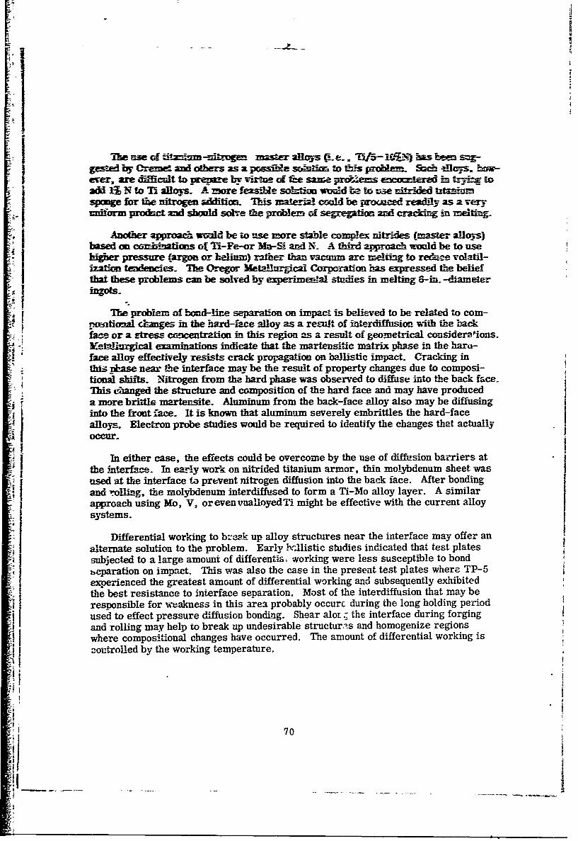
9'
Yhe use Gf dtim -mib-mgeti mister alIvys (C e. -1C 71 has been s-gested by Cremne and others as a prssmb&e soenioin to Cthis probem. Sach alloys. bvxw-ever, are diMcfilt to prepare by virtue of fne same prUems ewcoclered in trym toad 1 N to Ti alloys. A more feasibie soltkim wodd te to use mnitrled ti mspomge for Cme nitrogen additicon- 'Tis mir!1 coulid be prouaced £.ead-y as a vex~-=niform rodmc amd shwmW solve the problem of - and cracng m=tng
Another aproa& wvdd be to use more s!able com!ex nitrs-des (master alloys)based on corbinans of Ti-Fe-or Ma-Si and N. A thlid approach would be to useIigier pressure (argon or helium) rather than vacuum arc meltig to re&ee volatil-ization tedemces. The Oregor Metallurgical Corporation has expressed the beliefthat these problems can be solved by experimental studies in melting 6-in. -diameter
inos
The problem of boad-line separation on impact is believed to be related to com-pm,.- tional cmnges in the hard-face alloy as a re-ult of interdiffusion with the -backface or a Etress canctrion in this region as a result of geometrical consideralions.-etallargical examinations indicate that the martensitic matrix phase in the hard-face alloy effectively resists crack propagation on ballistic impact. Cracking inthis pase near the interface may be the result of property changes due to composi-tional shifts. Nitrogen from the hard phase was observed to diffidse into the back face.This c5unged the structure and composition of the hard face and may have produceda more brittle martensite. Aluminum from the back-face alloy also may be diffusinginto the front face. It is known that aluminum severely embrittles the hard-facealloys. Electron probe studies would be required to identify the changes that actuallyoccur.
In either case, the effects could be overcome by the use of diffusion barriers atthe interface. In early work on nitrided titanium armor, thin molybdenum sheet wasaused at the interface to prevent nitrogen diffusion into the back face. After bondingfand rolling, the molybdenum interdiffused to form a Ti-Mo alloy layer. A similar
approach using Mo, V, orevenvuaioyedTi might be effective with the current alloy7 systems.
Differential working to ba-2k up alloy structures near the interface may offer analternate solution to the problem. Early brIlistic studies indicated that test platessubjected to a large amount of differentis -working were less susceptible to bondbparation on impact. This was also the case in the present test plates where TP-5experienced the greatest amount of differential working and subsequently exhibitedthe best resistance to interface separation. Most of the interdiffusion that may beresponsible for weakness in this area probably occur. during the long holding periodused to effect pressure diffusion bonding. Shear alor; the interface during forgingand rolling may help to break up undesirable structur::.s and homogenize regionswhere compositional changes have occurred. The amount of differential working isJontroUed by the working temperature.
! 7i '70
co*sul of der w liey hrkisg besior
C-eometrical coisidraticpns offer still anolber solubwo to the jrobern ofbodlin separation- In all1 cases where the ftoat-ftce thicnd ess exceeded to eoiosite thickness, separati a1- !he bo d line appeared to occur more readily]is possible ta the back-face ao se in this case does not hare safficien s -paresist deformation (ewing) on ac-htr This would result in aVeY high tensilestress at the bond line. Increasing section tickrness shonld imrore bemavior inths rega-d- It is likely that the front-face thickness shnould be considerably lessthan 50 of the comnosite in order to achieve needed deformation resistance- Theoptimum thickness for dual-hardness steel is in the range of 35 to 50. With titan-i rm, however, it may be even less because of its lower strength and mwelus com-pared with steel- The seven dual-hardness titanium alloy test pates that had theleast resistance to separation adl had a 60:40 ratio alf front to r-ear face materqis.The one plate with the best performance, on the other hand, had a 50:50 ratio.I Studies of the effect of varyring thickness ratios are needed to determine theoptimum ratios for titanium. A slightly greater total section thickness also may beIrequired to provide needed stiffness. The test plates used in this study were 0. 625 in-thick, which is suitable for dual-hardness steel armor but may be somewhat on thelight side for titanium. A slightly higher aerial density than that used in these testsmay be desirable.
One of the critical components of the hard-face alloy is germanium. Additions
of 3 to 5% appear to be required to produce the desired combination of properties.A cursory survey was made of the germanium industry to determine if cost or avail-ability would preclude the use of this element as an alloy addition to titanium for use
in armor. Germanium is a byproduct of zinc smelting and is readily available aspurified metal suitable for alloying with titanium. The domestic supply is ample tomeet current demands for the next 10 years and can be increased significantly, if the
need arises,oy imports from central and South Africa. The largest processing plantin the world is in Belgium and has a capacity of 135,000 lb of oxide (65 wt% Ge)per year. Belgium is the major European producer. The major producer in theUnited States is Eagle Picher Company. Other U. S. producers include AmericanZinc Company, Sylvania Electric Products Company, and American Metal Climax.
Production and consumption figurE s are d-ifficult to find and have not been pub-lished in recent years. In 1963, U.S. industry consumed 20,000 lb of germanium.
Total prcduction amounted to 45,000 lb of primary metal and reprocessed scrap.Imports amounted to 30,748 lb of metal and oxide in 1961 but only 5,000 lb in 1963.At present, the metal is being stockpiled owing to a decline in demand. Engineer-ing economists at. Battelle Memorial institute have stated that up to 5000 lb per year
71
I
sug is a teqw b s-u a =*5- ;=n ef mse 3 mzoL
I Er. of ambs a-2Te'm ny-Ms=t=# - e~d
c~,is ma
72
0 55l-z "P p;eiT=9s bF L&~ ;ttawfaF f%=h s ir~lzs CE sud aid cm2= ca pose =nor isF2
39 02. Fe, --- 0.. 5 to I.. 0 FI N dvin pe Try t ecI w m Ptao AMtwRet abuorar- & c ~ ~ -a tb~rdeSS2BO fOr Th ftC~f fle Of 2 M2-dMS t =
Tb ~dallby can be r-mft e am' prcocess- d withmtan
flscaleap to arge t~gcts is - 2 to be fzIrrorle. Probems with=gtcrackmg drg w-iA are reLvve& to 211wir sge am m can beellmbmed _. imprm~ed comro-I of raw malerials and melfing feed stock..
(4 Te a ll- has ewceiemt c - - uii eomeriz liaf-strenth
AI2 n lean-beta. titanium alloys It bonds readily to these iiaterials
by the s'ibstitution of ironi for manganese-
(6) The hard alloy exhibits an excellent potential for multiliit capability. Thealloy de o z.fe nblitcipc n eae namne iia
(7) A Ti-MIl-2.W5o alloy is believed to have the best potential as a back-facealloy for dual-hardness titanium armor. The alloy has an exceptionallygood combination of strength and toughness and has a significantly higher[modulus than other high-strength alpha-beta alloys. The alloy does not
crdelaminate, or spall on ballistic impact.
73
~m st~ g EU! l Dfs btVsdd m6eS U cb ~ CI eCmre h * fe wo a &ft§nsw t&=iers ad * egb~h tle
GE IES~ S xdy. ffte cc~ a u&Zwsa zor is wacT-xSa Ile p ae l t i wtsa dr~
-ww of am :=~Frwd zweyIM Mc =urm a basd CMdM Czantt is
6-2 Z51O MMN
oft k---vi 0- O30- as 0-. W-cal AP ftr~as Es nquireO& Sruiz!!b f&Ewzg bcors sbd be e-M65dired ~~
(1) A stww o ogevimd2rdr ineeded to de~aestrate b4c1it of scu!d bgws cc Th Errd-fwe ailawIke s~w'!x simi be oomdeed en 6 to 8-f-- -&zrter imgais of 25 - 50 fr
Ge + S, e ~ *zd benffmg andSJ Of C2Yge
MA wyof gmamesinr& -riaes frthe m'1 imr~s opzstles i
arereuted. The study should :fclude the ys of dijsi m barriers :o
mn"imWz mopos-fio3a modi czions ci either side of The interface and
teueof rvfted rsamig gradtices to cc* rol srcture at theinefe.BaL-'!icic tests 'sithn both 0. Is- and 0-. 50-ca AP/M2 projectijes si!<xld be
I used to t:valuamat- bond iewegrity-
(3) A stzdy of ballistic: performance in 0-. 3G- 2nd 0.. 50- cal -AP/M2 tests isneeded to establish optimni total cornpcsite tbickness andi frocil-tc-rear
face thickness ratio-s for this type of material.(4) it is recomrae-Aad that a prcgram be conducted in three sequential tasks
inthe order ut~ind above-. Ihe results from each task should be care-fully evaluiatedi and assessed with respect to technical fleasibilit-y of the:1 overall concept before proceeding :o the neid task.
.el 74
IL E. EL 3aUlKmA; W. C. C m. EL A-. P "Ul Tes IN&%Slla al Ecsi3m - 7539. 76=m B ..o- AflEM VcL 242 Fab 1968.
2. A-. D- 3MxiQL-M mo M K.. 3gtQx~bU aca, A c Pre=s ftr.Ndw Tack, M~S. FP, W~3 - 1
3-. EL L Mca~fi, G-. W.. Baer3 amd L S.. Bw& 'tzs~ca1 Neu6arc- -BC21c Ttamm of ~ os TR~t an3sam TA-=b C4ip-
4- E W.. Wo=Ler, "-Bma Tmex~met ofIn m-RcM m-h Mcj~k~s,J-. mL Met- VL SO, M35- 52, 2M 2- 16
-5[
rill
- 7z
'm A C A C ; p f
~&. =-E f :
T. a,;= -
S -f-t-7
Z =.VZ C, 71-- it -
- :~--6.=- a = pZz5-
==
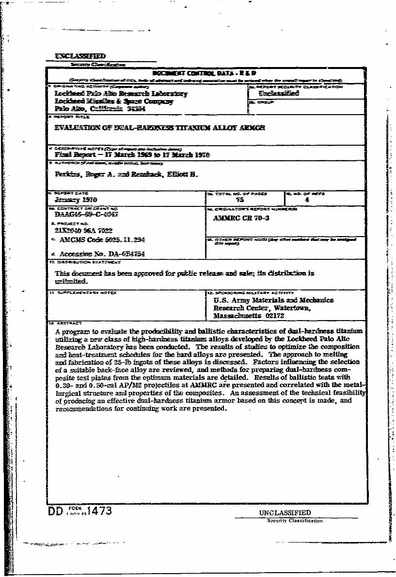
mIIOERTf CTMOL DATA - RI D
'U k~vdffatd P4b AIb Ue~a= Jabma j__ _ __ __
!Facbte Name" & quae -
DAAG -~47A3IMARC CE 70-3
U.S. Army Materials and MedmhicsI eerh etr Watertown,_____________________________ Mgsmhnsetts 02172
A erregram to evaluate the rociliyandi balfistic cactrstics of dual-l~ardoess ffftuinmuti-lizing a mez class of higb-bardmes-s titnitm alloys developed by the lockbeed Palo AltoReswarcn laartmyhas been coniltcted. The results of studies to optimize the compositionand beat-treatment schedales for the hard alloys are presented. The aproach to meltingandi 1koicatwn~ of 9-5-Rb ingots of these alloys is discussed. Factors influencing the selectionof a saltable back-face alloy are reviewed, and methods for preparing dual-hardness corn-posite testf plates &am the cntirnum nmterifals; are detailed. Results- of ballistic tests with-0. 30- and 0. 54-1cal AP/M2 Prqjectiles at -AXMC are presented and correlated with the metal-L-trgcal structurse and properties of the composites. An assessment of the technical feasibl
P- oroacin an effectivre dnal-hardness titanium armor based on this concept is made, and4 rec&mmenfations for continuing work are presented.L
DD ..,,J473 UNCLASSIFIED
Szcurity Classification
U - w
I
II
I i iliii
UIN SI FjecuiyCas~ct