Embed Size (px)
Citation preview

WBS LaserOperator’s Manual
IndustrIal FIber OptIcs
Model Numbers: IF UL08-635 IF UL30-635

*
Copyright © 2009Previous printings 2008, 2007, 2006, 2003, 2001, 1999
by Industrial Fiber OpticsRevision - I
Printed in the United States of America
* * *
All rights reserved. No part of this publication may be reproduced,stored in a retrieval system, or transmitted in any form or by any means
(electronic, mechanical, photocopying, recording, or otherwise)without prior written permission from Industrial Fiber Optics.
* * * * *

– i –
INtrOdUctIONThis manual provides information about Industrial Fiber Optics lasers model
numbers IF-UL08-635, and IF-UL30-635. It contains all the information you need to operate these lasers safely and knowledgeably, even if you are a novice to laser technology. Please read the manual carefully before operating the laser.
As soon as you receive this laser, inspect it and the shipping container for damage. If any damage is found, immediately refer to the section of this manual entitled ShIPmenT DAmAge ClAIm.
Industrial Fiber Optics makes every effort to incorporate state-of-the-art tech-nology, highest quality and dependability in its products. We constantly explore new ideas and products to best serve the rapidly expanding needs of industry and education. We encourage comments that you may have about our products, and we welcome the opportunity to discuss new ideas that may better serve your needs. For more information about our company and products refer to http//www.i-fiberoptics.com on the Internet.
Thank you for selecting this Industrial Fiber Optics product. We hope it meets your expectations and provides many hours of productive activity.
Sincerely,
the Industrial Fiber Optics team

– ii –

– iii –
TABLE OF CONTENTSIntroduction……………………….................…….....…………..…… iLASEr cLASSIFIcAtIONS............................................................ ivGENErAL…………................….............................……..…...…….. 1OPErAtIONAL INFOrMAtION…......................................………. 2
Electrical...................................................................................... 2Beam Controls............................................................................. 5Laser Specifications.................................................................... 6
SAFEtY….............................................…..............……..........……. 7Optical.......................................................................................... 7Electrical...................................................................................... 7
LASEr rEGULAtIONS…...................................................………. 8Certification/Identification............................................................ 8Classifications.............................................................................. 8Aperture Labels........................................................................... 9Additional References................................................................. 9
OPErAtING PrOcEdUrES.......................................................... 10Initial and Unmodulated Operation.............................................. 10Audio Modulation of the Laser Beam.......................................... 11RF Video Modulation of the Laser Beam.................................... 12Composite Video Modulation of the Laser Beam........................ 13
trOUBLESHOOtING…......................................................………. 14WArrANtY..................................................................................... 15SHIPMENt dAMAGE cLAIMS....................................................... 16SErVIcE ANd MAINtENANcE...................................................... 17

– iv –
LASEr cLASSIFIcAtIONS
All manufacturers of lasers used in the United States must conform to regulations admin-istered by the Center for Devices and Radiological Health (CDRH), a branch of the U.S. Department of Health and Human Services. CDRH categorizes lasers as follows:
Class Description
I A laser or laser system, which does not present a hazard to skin or eyes for any wavelength or exposure time. Exposure varies with wavelength. For ultraviolet, 2 to 4 µm exposures is less than from 8 nW to 8 µW. Visible light exposure varies from 4 µW to 200 µW, and for near-IR, the exposure is < 200 µW. Consult CDRH regula-tions for specific information.
II Any visible laser with an output less than 1 mW of power. Warning label requirements – yellow caution label stating maximum output of 1 mW. Generally used as classroom lab lasers, supermarket scanners and laser pointers
IIIa Any visible laser with an output over 1 mW of power with a maxi-mum output of 5 mW of power. Warning label requirements – red danger label stating maximum output of 5 mW. Also used as class-room lab lasers, in holography, laser pointers, leveling instruments, measuring devices and alignment equipment.
IIIb Any laser with an output over 5 mW of power with a maximum out-put of 500 mW of power and all invisible lasers with an output up to 400 mW. Warning label requirements – red danger label stating maximum output. These lasers also require a key switch for opera-tion and a 3.5-second delay when the laser is turned on. Used in many of the same applications as the Class IIIa when more power is required.
IV Any laser with an output over 500 mW of power. Warning label requirements – red danger label stating maximum output. These lasers are primarily used in industrial applications such as tooling, machining, cutting and welding. Most medical laser applications also require these high-powered lasers.

– 1 –
GENErAL
Industrial Fiber Optics’ family of diode lasers utilize the latest technology in miniature electronics and laser science. Applications of this technology include long-distance fiber optic communication networks, CD players and bar code scanners. A key element is the semiconductor diode laser, a tiny electronic microchip that operates as a laser.
Semiconductor diode lasers offer an important alternative to widely known and used helium-neon-gas (HeNe) lasers. Diode lasers are smaller, more efficient, and offer direct digital and analog modulation capabilities previously unavailable. Exceptional versatility makes this semiconductor technology an essential component of modern science, physics and industrial technology curriculums.
The Industrial Fiber Optics family of lasers vary primarily in their output power, wave-length, and modulation capability. They offer particular education value in their ability to increase and reinforce learning via fascination by being able to see all the internal elements. With these lasers, students will readily and enthusiastically learn about physical optics, fiber optics, light propagation, speed of light theory and measurement, laser communications, and much more!
Table 1. Metric prefixes and their meanings.
Prefix Symbol Multiple
tera T 1012 (trillion)
giga G 109 (billion)
mega M 106 (million)
kilo k 103 (thousand)
hecto h 102 (hundred)
deca da 101 (ten)
deci d 10-1 (tenth)
centi c 10-2 (hundredth)
milli m 10-3 (thousandth)
micro µ 10-6 (millionth)
nano n 10-9 (billionth)
pico p 10-12(trillionth)
femto f 10-15 (quadrillionth)

– 2 –
OPErAtIONAL INFOrMAtION
Electrical
All electrical controls are located at the rear of the laser chassis. A diagram of the rear view of the laser appears in Figure 1.
Figure 1. Rear view of laser showing electrical inputs and controls.
Following are descriptions of each item identified in Figure 1:
1. Power Jack (PWR)
All Industrial Fiber Optics lasers use a standard 2.1 mm DC power input jack to provide power to the laser. (An ON/OFF switch controls power from the jack to the electronic circuitry and lasing element.)
Power input to the laser must be applied from a low-voltage DC power source in the range of 10 to 15 volts, such as supplied with the laser. See Item 6 in this sec-tion for more information about the power adapter.
2. Switch (SW)
A push-button switch is located to the left of the 2.1 mm power jack. It controls power from the 2.1 mm power jack to the electronic circuitry and lasing element. When the Switch is closed (ON) it will be slightly depressed, and fully extended when is open (OFF).
– 3 –
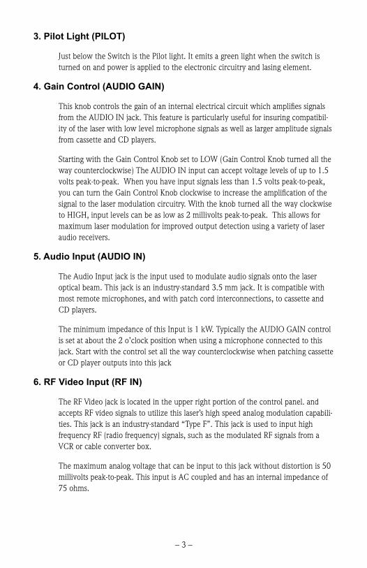
3. Pilot Light (PILOT)
Just below the Switch is the Pilot light. It emits a green light when the switch is turned on and power is applied to the electronic circuitry and lasing element.
4. Gain Control (AUDIO GAIN)
This knob controls the gain of an internal electrical circuit which amplifies signals from the AUDIO IN jack. This feature is particularly useful for insuring compatibil-ity of the laser with low level microphone signals as well as larger amplitude signals from cassette and CD players.
Starting with the Gain Control Knob set to LOW (Gain Control Knob turned all the way counterclockwise) The AUDIO IN input can accept voltage levels of up to 1.5 volts peak-to-peak. When you have input signals less than 1.5 volts peak-to-peak, you can turn the Gain Control Knob clockwise to increase the amplification of the signal to the laser modulation circuitry. With the knob turned all the way clockwise to HIGH, input levels can be as low as 2 millivolts peak-to-peak. This allows for maximum laser modulation for improved output detection using a variety of laser audio receivers.
5. Audio Input (AUDIO IN)
The Audio Input jack is the input used to modulate audio signals onto the laser optical beam. This jack is an industry-standard 3.5 mm jack. It is compatible with most remote microphones, and with patch cord interconnections, to cassette and CD players.
The minimum impedance of this Input is 1 kW. Typically the AUDIO GAIN control is set at about the 2 o’clock position when using a microphone connected to this jack. Start with the control set all the way counterclockwise when patching cassette or CD player outputs into this jack
6. RF Video Input (RF IN)
The RF Video jack is located in the upper right portion of the control panel. and accepts RF video signals to utilize this laser’s high speed analog modulation capabili-ties. This jack is an industry-standard “Type F”. This jack is used to input high frequency RF (radio frequency) signals, such as the modulated RF signals from a VCR or cable converter box.
The maximum analog voltage that can be input to this jack without distortion is 50 millivolts peak-to-peak. This input is AC coupled and has an internal impedance of 75 ohms.

– 4 –
7. Composite Video Input (COMP IN)
The Composite Video jack located belis the input used to modulate NTSC com-posite video signals onto the laser optical beam. This jack is an industry-standard yellow RCA jack. It will accept the composite video signal output by VCRs, DVD players and camcorders.
8. Power Adapter (not shown)
All Industrial Fiber Optics lasers sold in the United States come complete with a power adapter suitable for 60 Hz 110 VAC-to-VDC conversion. When shipped to in-ternational regions that are on a 50 Hz 220 VAC power grid, Industrial Fiber Optics will supply 220 VAC to 110 VAC step down transformers to be used in conjunction with the 110 VAC power adapters. It is strongly recommended that the power adapter furnished with the laser be the only supply used.
If you must use another power supply, it must be one with voltage output between 10 to 15 volts DC and minimum current capability of 150 milliamperes. Do not use a power supply which may generate spikes exceeding 36 volts.

– 5 –
Beam controls
1. Optics Mount
The Optics Mount is a nickel-plated aluminum cylinder with internal diameter of 3/4 inches and with 32 threads per inch. The threads facilitate the use of this laser in many optical experiments using mounted lenses, polarizers and spatial filters.
2. Beam Stop
The Beam Stop (also known as a beam attenuator) is required on lasers by federal regulations. When viewed from the rear of the laser, its handle protrudes from the right side of the optics mount. Its function is to mechanically block the laser beam when the handle is pushed downward. When the handle is pushed upward, the beam stop rotates and allows the laser beam to exit the lasing apparatus.
Figure 2. Front view of laser with Beam Stop blocking the laser beam.

– 6 –
LASEr SPEcIFIcAtIONS
Table 2. Laser specifications.
Parameter Value
OperatingInput voltage 10 to 15 Volts
Input current 60 to 125 milliamperes
Temperature 0° to 40° C
OpticalPolarization Linear
Wavelength 635 nm
Output power See label on underside of laser
Beam diameter 3.2 mm
Beam divergence, max. 2 milliradians
ElectricalRF modulation 100 Hz to 70 MHz
RF input, max. 50 mV peak-to-peak
Composite modulation 0 to 10 MHz
Composite input, max. 1 V peak-to-peak
Audio modulation 20 Hz to 10 MHz
Audio input, max. 1.5 V peak-to-peak
StorageDimensions 5.6 x 7.5 x 22 cm
Weight 400 grams
Temperature -20° to 50° C
Table 3. CDRH classifications for laser models.
Laser Model Classification Typical power levels
IF-UL08-635 CLASS II .75 to .90 mW
IF-UL30-635 CLASS IIIa 2.8 to 3.2 mW
Caution:Using controls, making adjustments, or performing procedures other than those speci-fied herein may result in hazardous radiation exposure.
– 7 –
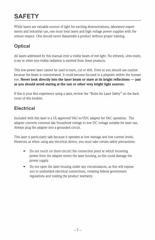
SAFEtYWhile lasers are valuable sources of light for exciting demonstrations, laboratory experi-ments and industrial use, one must treat lasers and high voltage power supplies with the utmost respect. One should never diassemble a product without proper training.
Optical
All lasers addressed by this manual emit a visible beam of red light. No infrared, ultra-violet, x-ray or other non-visible radiation is emitted from these products.
This low-power laser cannot be used to burn, cut or drill. Even so you should use caution because the beam is concentrated. It could become focused to a pinpoint within the human eye. Never look directly into the laser beam or stare at its bright reflections — just as you should avoid staring at the sun or other very bright light sources.
If this is your first experience using a laser, review the “Rules for Laser Safety” on the back cover of this booklet.
Electrical
Included with this laser is a UL-approved VAC-to-VDC adapter for VAC operation. The adapter converts common lab/household voltage to low DC voltage suitable for laser use. Always plug the adapter into a grounded circuit.
This laser is particularly safe because it operates at low wattage and low current levels. However, as when using any electrical device, you must take certain safety precautions:
• Donottouch(orshort-circuit)theconnectionpointatwhichincomingpower from the adapter enters the laser housing, as this could damage the power supply.
• Donotopenthelaserhousingunderanycircumstances,asthiswillexposeyou to unshielded electrical connections, violating federal government regulations and voiding the product warranty.
– 8 –
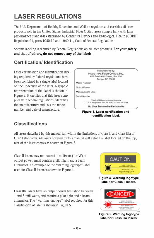
LASEr rEGULAtIONSThe U.S. Department of Health, Education and Welfare regulates and classifies all laser products sold in the United States. Industrial Fiber Optics lasers comply fully with laser performance standards established by Center for Devices and Radiological Health (CDRH) Regulation 21, parts 1040.10 and 1040.11, Code of Federal Regulations.
Specific labeling is required by Federal Regulations on all laser products. For your safety and that of others, do not remove any of the labels.
Certification/ Identification
Laser certification and identification label-ing required by federal regulations have been combined in a single label located on the underside of the laser. A graphic representation of that label is shown in Figure 3. It certifies that this laser com-plies with federal regulations; identifies the manufacturer; and lists the model number and date of manufacture.
Classifications
All lasers described by this manual fall within the limitations of Class II and Class IIIa of CDRH standards. All lasers covered by this manual will exhibit a label located on the top, rear of the laser chassis as shown in Figure 7.
Class II lasers may not exceed 1 milliwatt (1 mW) of output power, must contain a pilot light and a beam attenuator. An example of the “warning logotype” label used for Class II lasers is shown in Figure 4.
Class IIIa lasers have an output power limitation between 1 and 5 milliwatts, and require a pilot light and a beam attenuator. The “warning logotype” label required for this classification of laser is shown in Figure 5.
Figure 3. Laser certification andidentification label.
Figure 4. Warning logotype label for Class II lasers.
Figure 5. Warning logotype label for Class IIIa lasers.

– 9 –
Aperture Labels
Federal regulations also require that the laser emission aperture/port be labeled. A graphic representation of that label is shown in Figure 6. Location of this label is shown in Figure 2.
Figure 6. Beam aperture label.
Additional References
For more information about lasers and laser standards, contact your local U.S. Department of Health and Human Services, or write to the agency’s headquarters at 1390 Piccard Dr., Rockville, MD 20850.
For U.S. guidelines on laser classifications and health standards, refer to the American National Standards Institute (ANSI) specifications governing lasers and laser safety. The guidelines are published by the Laser Institute of America, 12424 Research Parkway, Suite 130, Orlando, FL 32826.
Figure 7. Top view of laser showing the location ofthe “Warning logotype” label for a Class IIIa laser.

– 10 –
OPErAtING PrOcEdUrES
Initial and Unmodulated Operation
1. Review the laser safety steps on the back cover of this manual if this is your first time operating a laser.
2. Point the laser toward a wall or other dull non-reflecting surface.
3. Push the beam stop’s handle downward to its closed position.
4. Make sure the laser’s ON/OFF switch (SW) is in its OFF position. (The push button should be in its extended position.)
5. Plug the 110* VAC-to-DC power adapter (provided with the laser) into an AC wall outlet.
6. Plug the cord from the power adapter into the power jack (PWR) located on the rear of the laser.
7. Depress the ON/OFF switch (SW) on the control panel of the laser until it clicks into the ON position. (The switch should be slightly depressed.)
8. The pilot light (green LED) below the ON/OFF switch should now be lit, showing that the laser is on.
9. Push the beam stop’s handle upward, to its open position.
10. Observe the red beam striking the wall, or other surface, in the direction which the laser is pointed.
* A 220 VAC to 110 VAC step down transformer will be provided to customers on 220 VAC power grids outside of North America
Important!
If you must use a power adapter other than the one supplied with this laser, check the section entitled Operational Information in this manual to ensure the power adapter’s voltage and current levels are within recommended specifications.

– 11 –
Audio Modulation of the Laser Beam
We will outline the steps for modulating the Industrial Fiber Optics’ laser with audio signals. Because we do not know what receiver you will be using to convert the optical signal on the laser beam, please refer to that receiver’s instruction manual as directed in the procedure below.
1. Check to ensure that the audio signal inputs you plan to use do not exceed the specifications given in the Operational Information section of this manual.
2. Turn off all power to the source which will provide the modulation input to the laser.
3. Push the beam stop to its closed position, and make sure the laser’s ON/OFF switch is OFF. (The button should be extended and the pilot light no longer illuminated.)
4. Plug a microphone, or other audio source into the analog input labeled AUDIO IN on the rear of the laser. If necessary, use an electrical adapter to convert the audio plug of the signal source to the 3.5 mm audio jack on the laser.
5. Point the laser toward a wall or other non-reflecting dull surface.
6. Set up your laser receiver, referring to its manual for operating procedure.
7. Press the ON/OFF switch (SW) on the control panel of the laser. The laser now should be on, as indicated by the pilot light.
8. Turn on the power to the signal source.
9. The amplitude of the exiting laser light should now be modulated by the input signals.
10. Rotate the beam stop’s handle upward to its open position.
11. Target the laser beam on the light detector found on the laser receiver.
12. Position the receiver or laser as needed, so the laser light beam strikes the center of the receiver detector.
13. Adjust the audio level applied to the laser, the AUDIO GAIN knob on the rear of the laser, and the gain on the laser receiver as needed to most clearly receive signals.
Your laser and receiver should now be functioning as a free-space optical communications link. If you are using a microphone input you should hear your voice coming from the receiver.

– 12 –
RF Video Modulation of the Laser Beam
We will outline the steps for modulating the Industrial Fiber Optics laser with RF video signals. Because we do not know what receiver you will be using to convert the optical signal on the laser beam, please refer to that receiver’s instruction manual as directed in the procedure below.
1. Check to ensure that the RF signal inputs you plan to use do not exceed the specifications given in the Operational Information section of this manual.
2. Turn off all power to the source which will provide the modulation input to the laser.
3. Push the beam stop to its closed position, and make sure the laser’s ON/OFF switch is OFF. (The button should be extended and the pilot light no longer illuminated.)
4. Connect one end of a Type F coaxial cable to the antenna output of a VCR or cable converter box. Connect the other end to the RF IN jack on the rear of the laser. Set the VCR or cable box to channel 3 or 4 as appropriate.
5. Point the laser toward a wall or other non-reflecting dull surface.
6. Set up your laser receiver, referring to its manual for operating procedure. If you are using a IF-VRII receiver from Industrial Fiber Optics it will contain all the necessary hardware and instruction information.
7. Press the ON/OFF switch (SW) on the control panel of the laser. The laser now should be on, as indicated by the pilot light.
8. Turn on the power to the VCR or cable converter.
9. The amplitude of the exiting laser light should now be modulated by the RF input signals.
10. Rotate the beam stop’s handle upward to its open position.
11. Target the laser beam on the light detector found on the laser receiver.
12. Position the receiver or laser as needed, so the laser light beam strikes the center of the receiver detector.
Your laser and receiver should now be functioning as a free-space optical communications link. If you are using a VCR as the electrical modulation source, and a video receiver con-nected to a television, you should now see a picture and hear sound from the television.

– 13 –
Composite Video Modulation of the Laser Beam
We will outline the steps for modulating the Industrial Fiber Optic laser with composite video signals. Because we do not know what receiver you will be using to convert the opti-cal signal on the laser beam, please refer to that receiver’s instruction manual as directed in the procedure below.
1. Check to ensure that the composite video signal inputs you plan to use do not exceed the specifications given in the Operational Information section of this manual.
2. Turn off all power to the source which will provide the modulation input to the laser.
3. Push the beam stop to its closed position, and make sure the laser’s ON/OFF switch is OFF. (The button should be extended and the pilot light no longer illuminated.)
4. Insert one end of an RCA patch cord into the composite video jack (the yellow RCA jack) of a VCR, DVD player or camcorder, and the remaining end into to the analog input COMP IN on the rear of the laser.
5. Point the laser toward a wall or other non-reflecting dull surface.
6. Set up your video laser receiver, referring to its manual for operating pro-cedure.
7. Press the ON/OFF switch (SW) on the control panel of the laser. The laser now should be on, as indicated by the pilot light.
8. Turn on the power to the VCR or camcorder.
9. The amplitude of the exiting laser light should now be modulated by the video input signal.
10. Rotate the beam stop’s handle upward to its open position.
11. Target the laser beam on the light detector found on the laser receiver.
12. Position the receiver or laser as needed, so the laser light beam strikes the center of the receiver detector.
Your laser and receiver should now be functioning as a free-space optical communications link. If you are using a VCR as the electrical modulation source, and a video receiver con-nected to a television, you should now see a picture on the television.
– 14 –
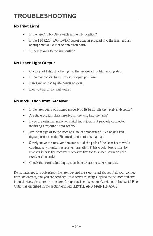
trOUBLESHOOtINGNo Pilot Light
• Isthelaser’sON/OFFswitchintheONposition?
• Isthe110(220)VAC-to-VDCpoweradapterpluggedintothelaserandanappropriatewalloutletorextensioncord?
• Istherepowertothewalloutlet?
No Laser Light Output
• Checkpilotlight.Ifnoton,gotothepreviousTroubleshootingstep.
• Isthemechanicalbeamstopinitsopenposition?
• Damagedorinadequatepoweradapter.
• Lowvoltagetothewalloutlet.
No Modulation from Receiver
• Isthelaserbeampositionedproperlysoitsbeamhitsthereceiverdetector?
• Aretheelectricalplugsinsertedallthewayintothejacks?
• Ifyouareusingananalogordigitalinputjack,isitproperlyconnected,includinga“ground”connection?
• Areinputsignalstothelaserofsufficientamplitude?(Seeanaloganddigital portions in the Electrical section of this manual.)
• Slowlymovethereceiverdetectoroutofthepathofthelaserbeamwhilecontinuously monitoring receiver operation. (This would desensitize the receiver in case the receiver is too sensitive for this laser [saturating the receiver element].)
• Checkthetroubleshootingsectioninyourlaserreceivermanual.
Do not attempt to troubleshoot the laser beyond the steps listed above. If all your connec-tions are correct, and you are confident that power is being supplied to the laser and any input devices, please return the laser for appropriate inspection/servicing to Industrial Fiber Optics, as described in the section entitled SERVICE AND MAINTENANCE.

– 15 –
WArrANtYIndustrial Fiber Optics lasers are warranted against defects in materials and workmanship for 4 years. The warranty will be voided if the laser components have been damaged or mishandled by the buyer, including entry to the laser housing and/or removal of screws.
Industrial Fiber Optics’ warranty liability is limited to repair or replacement of any defective unit at the company’s facilities, and does not include attendant or consequential damages. Repair or replacement may be made only after failure analysis at the factory. Authorized warranty repairs are made at no charge, and are guaranteed for the balance of the original warranty.
Industrial Fiber Optics will pay the return freight and insurance charges for warranty repair within the continental United States by United Parcel Service or Parcel Post. Any other delivery means must be paid for by the customer.
The costs of return shipments for lasers no longer under warranty must be paid by the customer. If an item is not under warranty, repairs will not be undertaken until the cost of such repairs has been approved, in writing, by the customer. Typical repair costs range from $50 - $125 and usually take two to three weeks to complete.
When returning items for analysis and possible repair, please do the following:
• Inaletter,describetheproblem,persontocontact,phonenumberandreturn address.
• Packthelaser,poweradapter,manualandlettercarefullyinastrongboxwith adequate packing material, to prevent damage in shipment.
• Shipthepackageto:
IndustrIal FIber OptIcs1725 West 1st street
tempe, AZ 85281-7622UsA

– 16 –
SHIPMENt dAMAGE cLAIMSIf damage to an Industrial Fiber Optics product should occur during shipping, it is impera-tive that it be reported immediately, both to the carrier and the distributor or salesperson from whom the item was purchased. DO NOT CONTACT INDUSTRIAL FIBER OPTICS.
Time is of the essence because damage claims submitted more than five days after delivery may not be honored. If shipping damage has occurred during shipment, please do the fol-lowing:
• Makeanoteofthecarriercompany,thenameofthecarrieremployee,thedate and the time of the delivery.
• Keepallpackingmaterial.
• Inwriting,describethenatureofdamagetotheproduct.
• Incasesofseveredamage,donotattempttousetheproduct(includingattaching it to a power source).
• Notifythecarrierimmediatelyofanydamagedproduct.
• Notifythedistributorfromwhomthepurchasewasmade.
------------------------------

– 17 –
SErVIcE ANd MAINtENANcEPeriodic maintenance and service of this laser are not required. The warranty will be voided if entry has been made to the laser housing and/or removal of screws.
In the unlikely event this laser malfunctions and you wish to have it repaired, please do the following:
• Inwriting,describetheproblem,persontocontact,phonenumber,andreturn address.
• Carefullypackthelaser,poweradapter,manualandwrittendescriptionina strong box with sufficient packing material to prevent damage in ship-ment.
• Shipthepackageto:
ndustrIal FIber OptIcs1725 West 1st street
tempe, AZ 85281-7622UsA
If you would like to view our products on the Internet go to: www.i-fiberoptics.com

12 0096
Rules for Laser Safety• Lasers produce a very intense beam of light. Treat them with respect. Most
educational lasers have an output of less than 3 milliwatts, and will not harm the skin.
• Never look into the laser aperture while the laser is turned on! PERMANENT EYE DAMAGE COULD RESULT.
• Never stare into the oncoming beam. Never use magnifiers (such as binoculars or telescopes) to look at the beam as it travels – or when it strikes a surface.
• Never point a laser at anyone’s eyes or face, no matter how far away they are.
• When using a laser in the classroom or laboratory, always use a beam stop, or project the beam to areas, which people won’t enter or pass through.
• Never leave a laser unattended while it is turned on – and always unplug it when it’s not actually being used.
• Remove all shiny objects from the area in which you will be working. This includes rings, watches, metal bands, tools, and glass. Reflections from the beam can be nearly as intense as the beam itself.
• Never disassemble or try to adjust the laser’s internal components. Electric shock could result.