Embed Size (px)
Citation preview
WaveMark Procedure No. 99-0030 Rev. C
6-Channel Multiplexer
P/N 03-0004 Assembly and Configuration
Procedure

WaveMark, Inc. - Proprietary and Confidential
99-0030 Rev. C Page 2 of 21
Notice of FCC Compliance Note: This equipment has been tested and found to comply with the limits for a Class A digital device, pursuant to Part 15 of the FCC Rules. These limits are designed to provide reasonable protection against harmful interference when the equipment is operated in a commercial environment. This equipment generates, uses, and can radiate radio frequency energy and, if not installed and used in accordance with the instruction manual, may cause harmful interference to radio communications. Operation of this equipment in a residential area is likely to cause harmful interference in which case the user will be required to correct the interference at his own expense. Changes or modifications not expressly approved by WaveMark, Inc. could void the user’s authority to operate the equipment. FCC Limited Modular Approval applies only to cabinets that have been expressly approved. Alternate configurations not listed below must be tested. Limited Modular Approval UQY-HF1000A applies to: HF1000, HFH1000, HFS1000 This device complies with Part 15 of the FCC Rules. Operation is subject to the following two conditions: (1) this device may not cause harmful interference, and (2) this device must accept any interference received, including interference that may cause undesired operation. This product must be professionally activated by WaveMark trained personnel and must only be serviced by WaveMark trained service personnel.
Notice of Industrie Canada Compliance Operation is subject to the following two conditions: (1) this device may not cause interference, and (2) this device must accept any interference, including interference that may cause undesired operation of the device.
WaveMark, Inc. - Proprietary and Confidential
99-0030 Rev. C Page 3 of 21
Document Revision History Rev. Notes/Changes Date
A First Release – ECO-0065 11 Aug 2008
B Add label and notes for FCC Limited Modular Approval 6 Nov 2008
C Added additional FCC notice 5 Dec 2008

WaveMark, Inc. - Proprietary and Confidential
99-0030 Rev. C Page 4 of 21
Table of Contents
1. Scope ...................................................................................................................... 5
2. Safety ...................................................................................................................... 5
3. Assembling the Mux/Reader Assembly - P/N 04-0008 ........................................ 6
Pick List ..................................................................................................................................................... 6
Tools and Test Equipment Required ........................................................................................................ 6
Programming ............................................................................................................................................ 7
Assembly ................................................................................................................................................ 10
Configuration........................................................................................................................................... 15
Testing .................................................................................................................................................... 18
Labeling .................................................................................................................................................. 19
4. Assembling the Mux RF to Data Assembly - P/N 03-0004 ................................ 20
Pick List ................................................................................................................................................... 20
Tools and Test Equipment Required ...................................................................................................... 20
Assembly ................................................................................................................................................ 20
Testing .................................................................................................................................................... 21
Labeling .................................................................................................................................................. 21

WaveMark, Inc. - Proprietary and Confidential
99-0030 Rev. C Page 5 of 21
1. Scope This procedure provides all the information needed to assemble and configure the 6-Channel Multiplexer (Mux) P/N 03-0004.
2. Safety
Before you pickup one tool you need to be committed to build safely. If needed, secure a set of safety glasses as well as gloves and use them. Be sure the area selected for build is free of clutter and adequate space is available.
It is your responsibility and an integral part of your job to work safely! If you are unfamiliar with some of the tools you need to use in assembly or the build procedures are unclear, ask for assistance!
WaveMark, Inc. - Proprietary and Confidential
99-0030 Rev. C Page 6 of 21
3. Assembling the Mux/Reader Assembly - P/N 04-0008
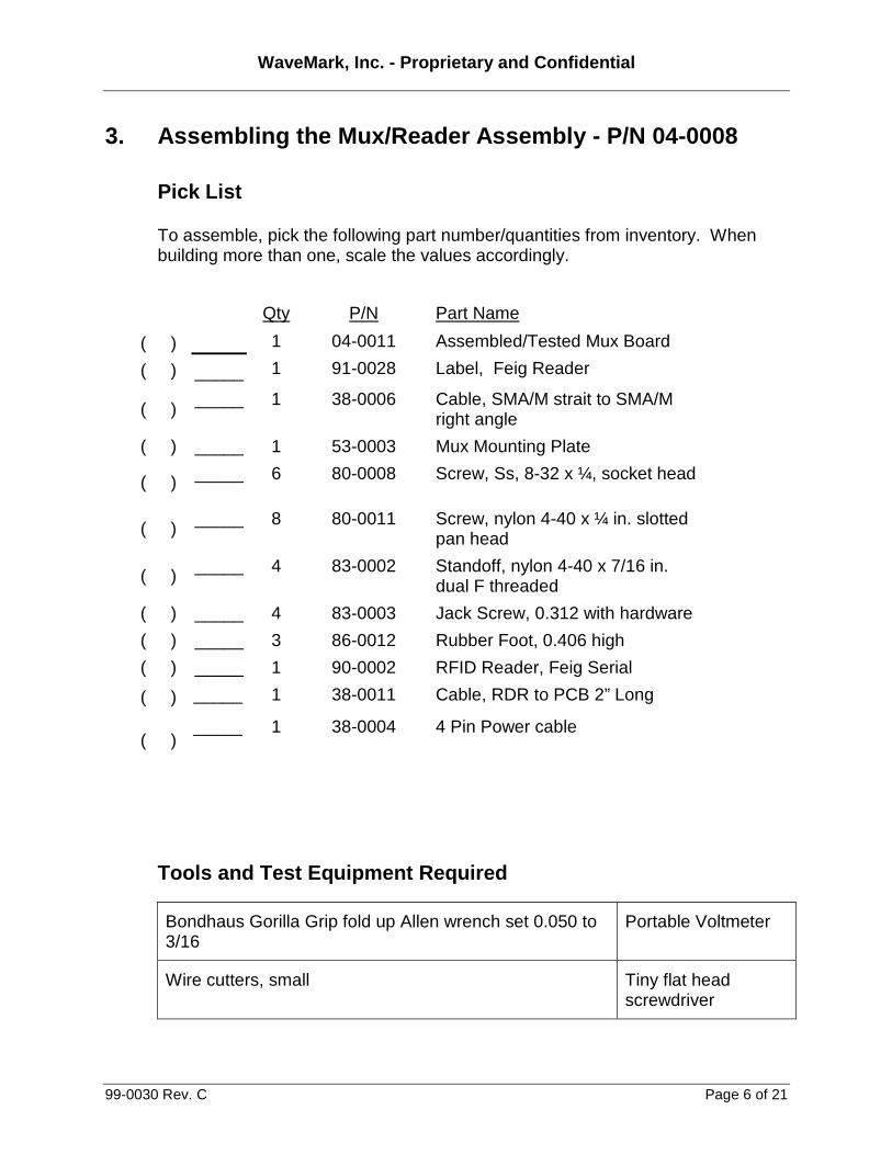
Pick List
To assemble, pick the following part number/quantities from inventory. When building more than one, scale the values accordingly.
Qty P/N Part Name
( )
( )
_____
1
1
04-0011
91-0028
Assembled/Tested Mux Board
Label, Feig Reader
( ) _____ 1 38-0006 Cable, SMA/M strait to SMA/M
right angle
( ) _____ 1 53-0003 Mux Mounting Plate
( ) _____ 6 80-0008 Screw, Ss, 8-32 x ¼, socket head
( ) _____ 8 80-0011 Screw, nylon 4-40 x ¼ in. slotted pan head
( ) _____ 4 83-0002 Standoff, nylon 4-40 x 7/16 in. dual F threaded
( ) _____ 4 83-0003 Jack Screw, 0.312 with hardware
( ) _____ 3 86-0012 Rubber Foot, 0.406 high
( ) _____ 1 90-0002 RFID Reader, Feig Serial
( ) _____ 1 38-0011 Cable, RDR to PCB 2” Long
( ) _____ 1 38-0004 4 Pin Power cable
Tools and Test Equipment Required
Bondhaus Gorilla Grip fold up Allen wrench set 0.050 to 3/16
Portable Voltmeter
Wire cutters, small Tiny flat head screwdriver
WaveMark, Inc. - Proprietary and Confidential
99-0030 Rev. C Page 7 of 21
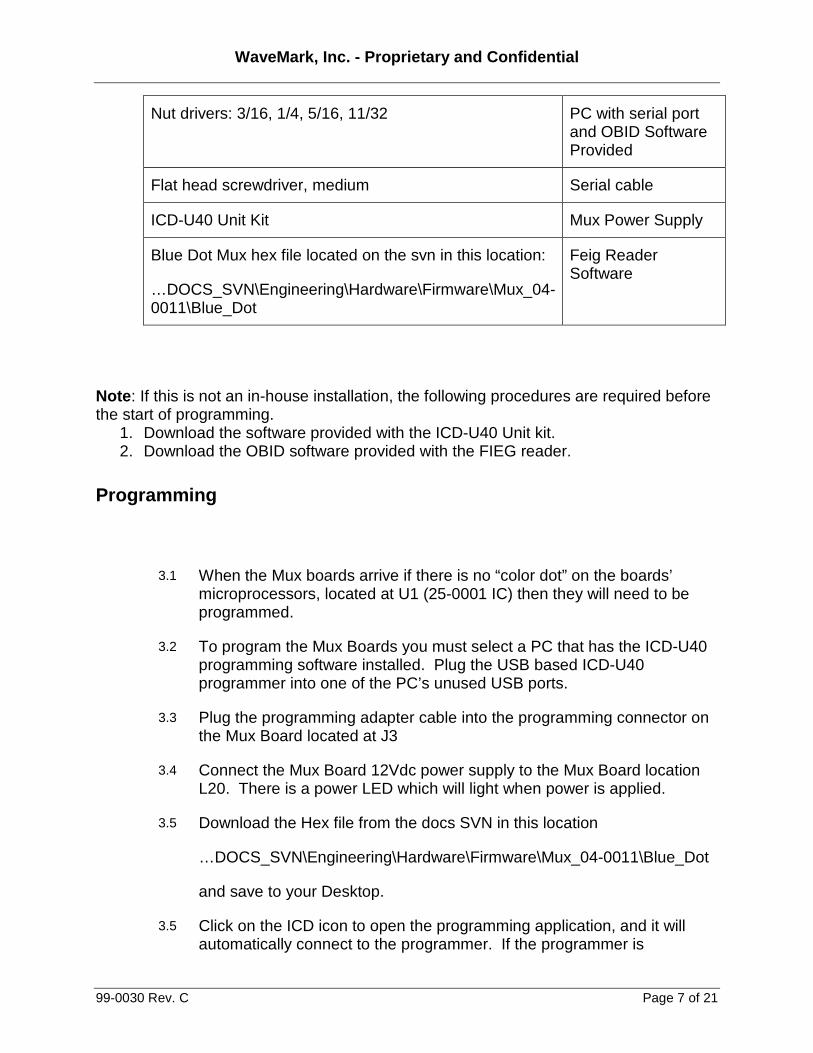
Nut drivers: 3/16, 1/4, 5/16, 11/32 PC with serial port and OBID Software Provided
Flat head screwdriver, medium Serial cable
ICD-U40 Unit Kit Mux Power Supply
Blue Dot Mux hex file located on the svn in this location:
…DOCS_SVN\Engineering\Hardware\Firmware\Mux_04-0011\Blue_Dot
Feig Reader Software
Note: If this is not an in-house installation, the following procedures are required before the start of programming.
1. Download the software provided with the ICD-U40 Unit kit. 2. Download the OBID software provided with the FIEG reader.
Programming
3.1 When the Mux boards arrive if there is no “color dot” on the boards’ microprocessors, located at U1 (25-0001 IC) then they will need to be programmed.
3.2 To program the Mux Boards you must select a PC that has the ICD-U40 programming software installed. Plug the USB based ICD-U40 programmer into one of the PC’s unused USB ports.
3.3 Plug the programming adapter cable into the programming connector on the Mux Board located at J3
3.4 Connect the Mux Board 12Vdc power supply to the Mux Board location L20. There is a power LED which will light when power is applied.
3.5 Download the Hex file from the docs SVN in this location
…DOCS_SVN\Engineering\Hardware\Firmware\Mux_04-0011\Blue_Dot
and save to your Desktop.
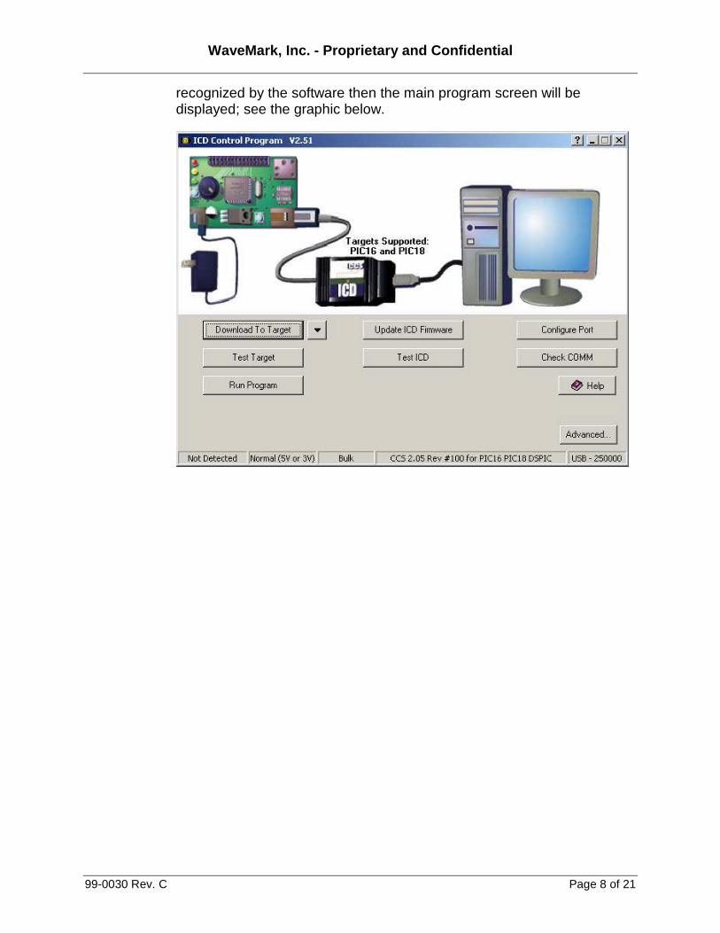
3.5 Click on the ICD icon to open the programming application, and it will automatically connect to the programmer. If the programmer is
WaveMark, Inc. - Proprietary and Confidential
99-0030 Rev. C Page 8 of 21
recognized by the software then the main program screen will be displayed; see the graphic below.
WaveMark, Inc. - Proprietary and Confidential
99-0030 Rev. C Page 9 of 21
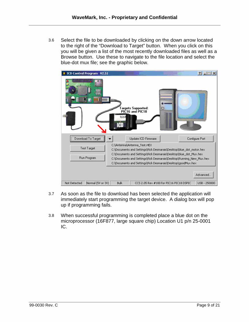
3.6 Select the file to be downloaded by clicking on the down arrow located to the right of the “Download to Target” button. When you click on this you will be given a list of the most recently downloaded files as well as a Browse button. Use these to navigate to the file location and select the blue-dot mux file; see the graphic below.
3.7 As soon as the file to download has been selected the application will immediately start programming the target device. A dialog box will pop up if programming fails.
3.8 When successful programming is completed place a blue dot on the microprocessor (16F877, large square chip) Location U1 p/n 25-0001 IC.
WaveMark, Inc. - Proprietary and Confidential
99-0030 Rev. C Page 10 of 21
Assembly
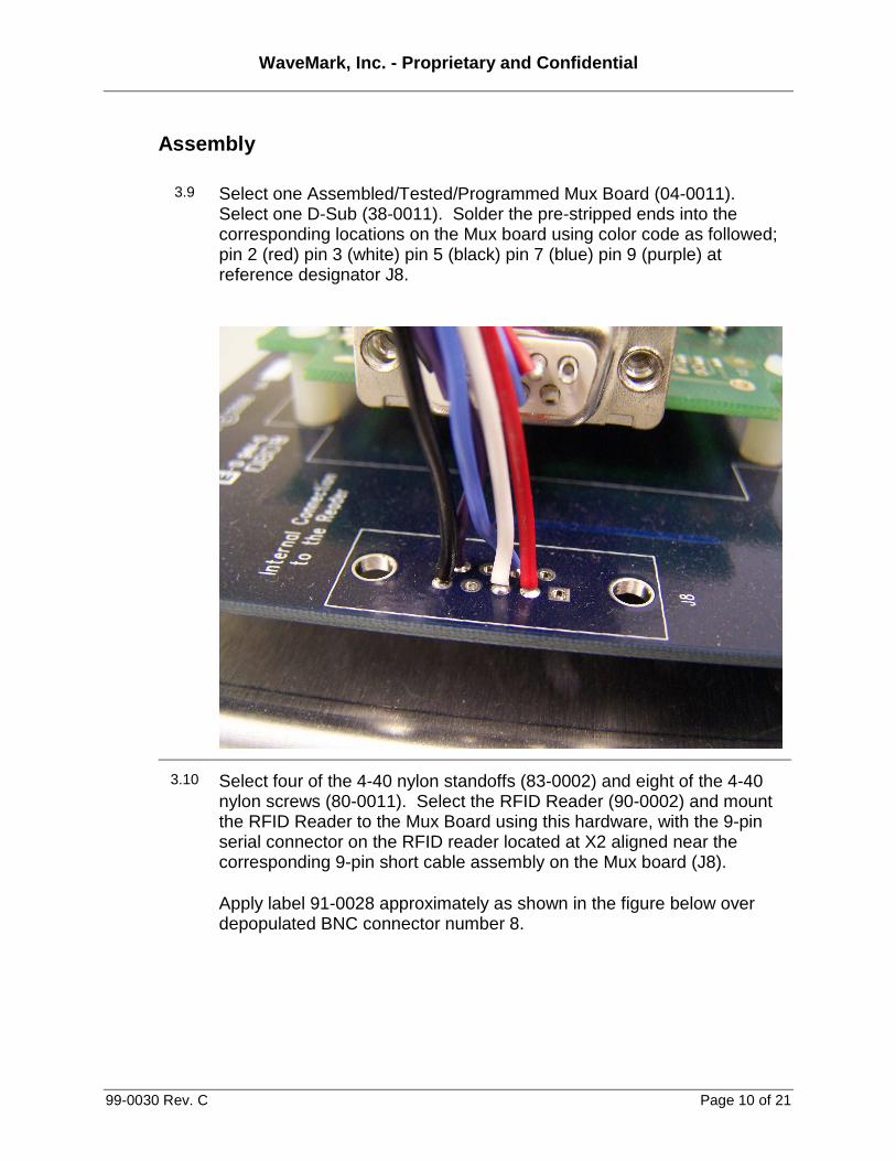
3.9
Select one Assembled/Tested/Programmed Mux Board (04-0011). Select one D-Sub (38-0011). Solder the pre-stripped ends into the corresponding locations on the Mux board using color code as followed; pin 2 (red) pin 3 (white) pin 5 (black) pin 7 (blue) pin 9 (purple) at reference designator J8.
3.10 Select four of the 4-40 nylon standoffs (83-0002) and eight of the 4-40 nylon screws (80-0011). Select the RFID Reader (90-0002) and mount the RFID Reader to the Mux Board using this hardware, with the 9-pin serial connector on the RFID reader located at X2 aligned near the corresponding 9-pin short cable assembly on the Mux board (J8).
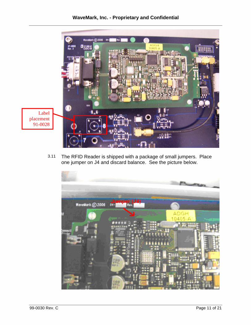
Apply label 91-0028 approximately as shown in the figure below over depopulated BNC connector number 8.
WaveMark, Inc. - Proprietary and Confidential
99-0030 Rev. C Page 11 of 21
3.11 The RFID Reader is shipped with a package of small jumpers. Place one jumper on J4 and discard balance. See the picture below.
Label placement
91-0028

WaveMark, Inc. - Proprietary and Confidential
99-0030 Rev. C Page 12 of 21
3.12 Select one SMA Strait to Right Angle Cable (38-0006) and attach the right angled end to the SMA connector on the RFID Reader and the straight end to the SMA connector on the Mux Board located at J16.
3.14 Remove Kapton Tape from 8-position DIP Switch located at SW1
3.15 On the 8-position DIP switch on the Mux board, set the switches so switch number 3 is OFF and all other switches are ON.
WaveMark, Inc. - Proprietary and Confidential
99-0030 Rev. C Page 13 of 21
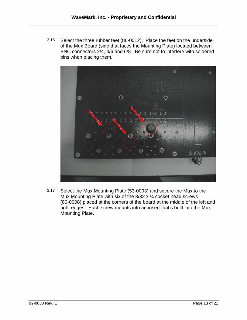
3.16 Select the three rubber feet (86-0012). Place the feet on the underside of the Mux Board (side that faces the Mounting Plate) located between BNC connectors 2/4, 4/6 and 6/8. Be sure not to interfere with soldered pins when placing them.
3.17 Select the Mux Mounting Plate (53-0003) and secure the Mux to the Mux Mounting Plate with six of the 8/32 x ¼ socket head screws (80-0008) placed at the corners of the board at the middle of the left and right edges. Each screw mounts into an insert that’s built into the Mux Mounting Plate.
WaveMark, Inc. - Proprietary and Confidential
99-0030 Rev. C Page 14 of 21
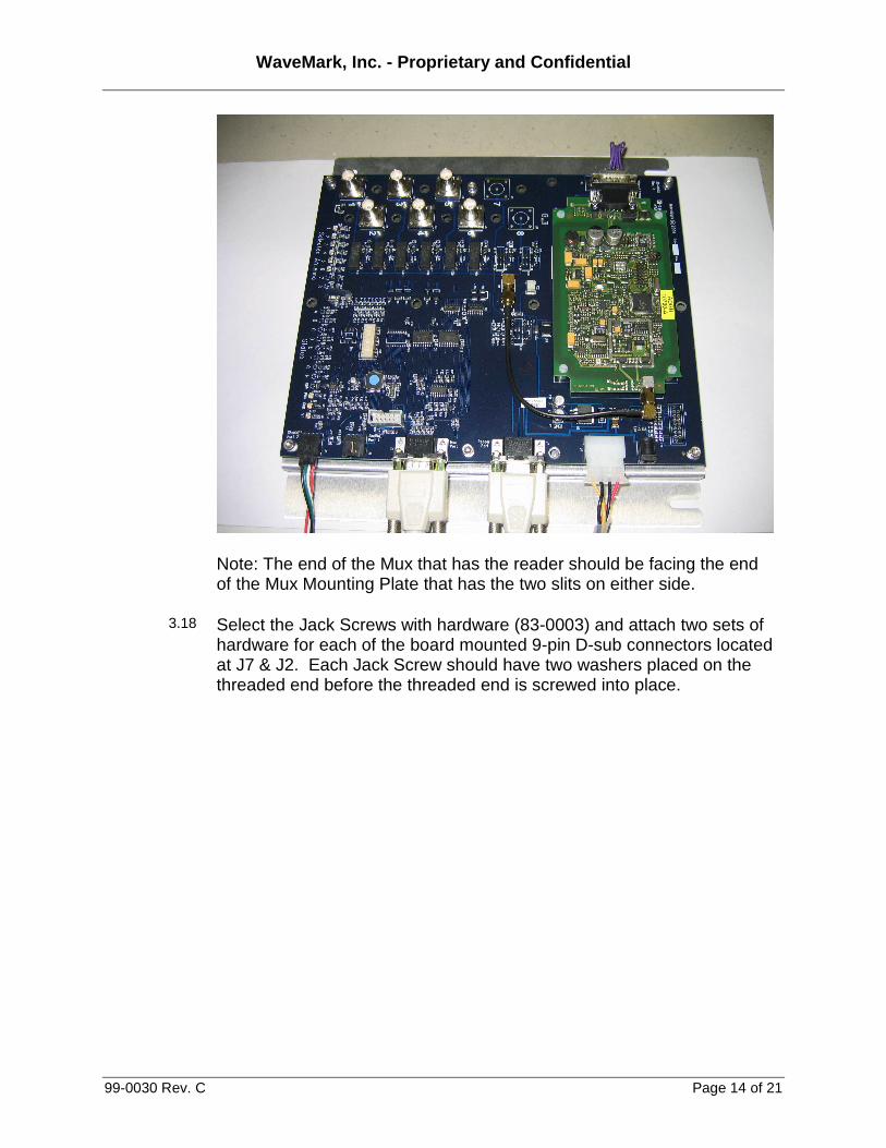
Note: The end of the Mux that has the reader should be facing the end of the Mux Mounting Plate that has the two slits on either side.
3.18 Select the Jack Screws with hardware (83-0003) and attach two sets of hardware for each of the board mounted 9-pin D-sub connectors located at J7 & J2. Each Jack Screw should have two washers placed on the threaded end before the threaded end is screwed into place.
WaveMark, Inc. - Proprietary and Confidential
99-0030 Rev. C Page 15 of 21
Configuration
3.19 Be sure no other FIEG readers are connected to the PC.
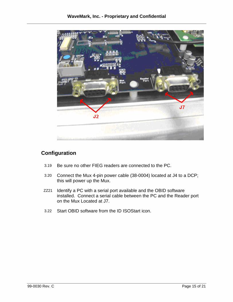
3.20 Connect the Mux 4-pin power cable (38-0004) located at J4 to a DCP; this will power up the Mux.
ZZ21 Identify a PC with a serial port available and the OBID software installed. Connect a serial cable between the PC and the Reader port on the Mux Located at J7.
3.22 Start OBID software from the ID ISOStart icon.
WaveMark, Inc. - Proprietary and Confidential
99-0030 Rev. C Page 16 of 21
3.23 The reader should be auto detected by the software; to move forward select the Feig reader. Only one Feig reader should be connected to the PC (including serial and USB ports) at one time.
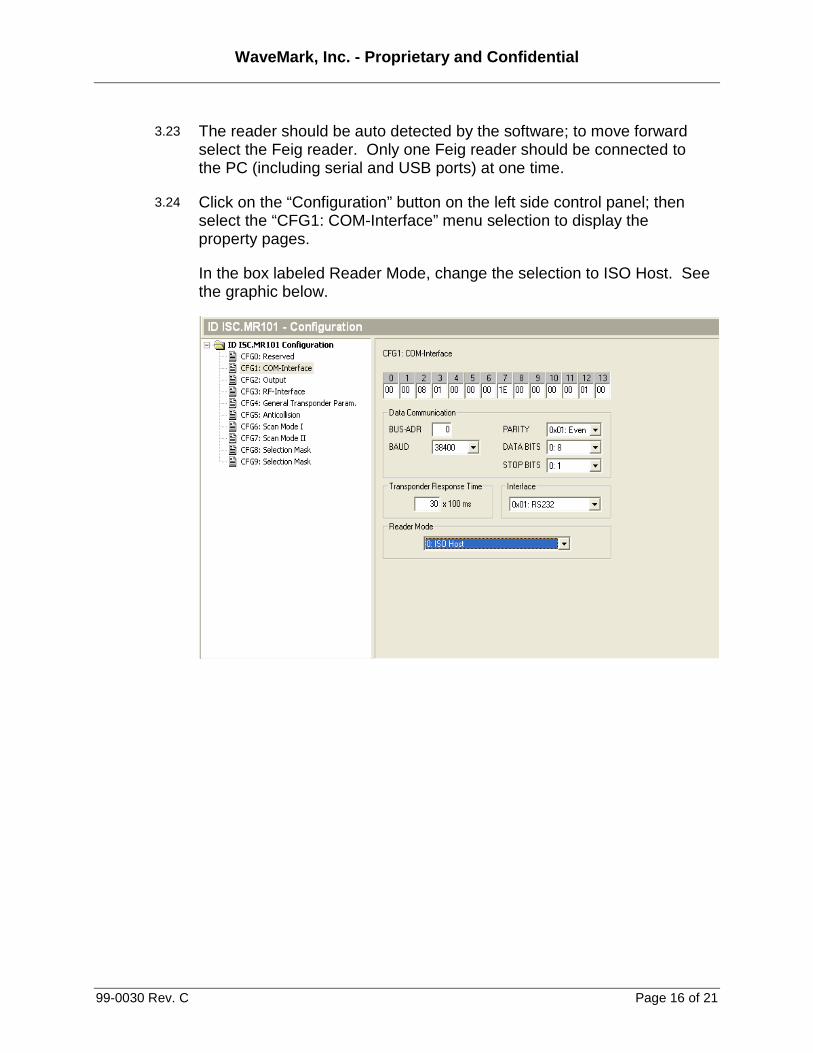
3.24 Click on the “Configuration” button on the left side control panel; then select the “CFG1: COM-Interface” menu selection to display the property pages.
In the box labeled Reader Mode, change the selection to ISO Host. See the graphic below.
WaveMark, Inc. - Proprietary and Confidential
99-0030 Rev. C Page 17 of 21
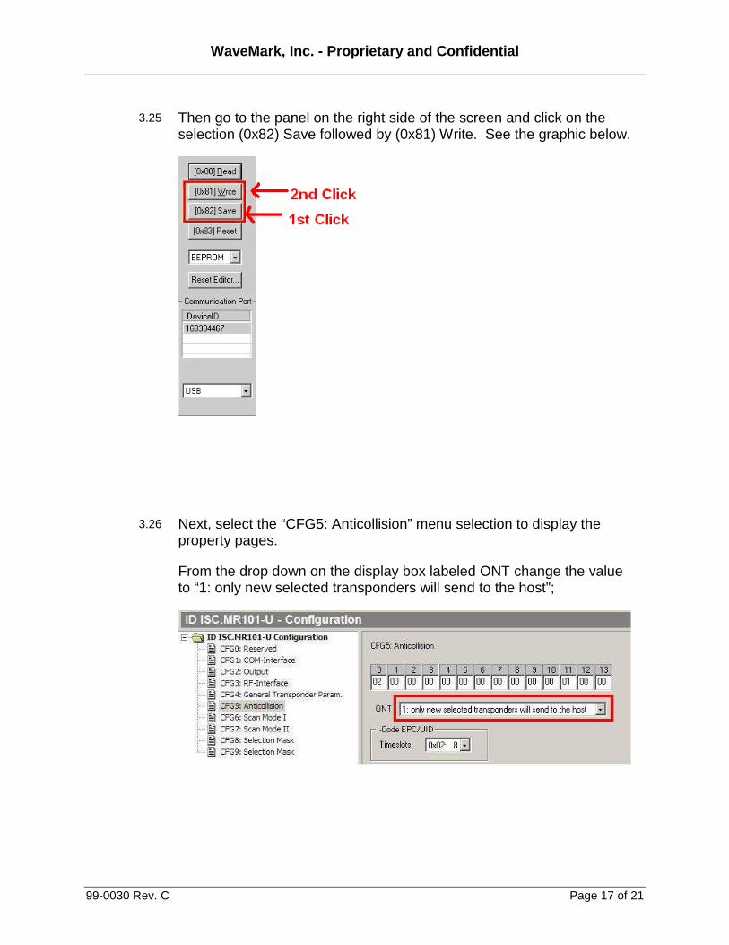
3.25 Then go to the panel on the right side of the screen and click on the selection (0x82) Save followed by (0x81) Write. See the graphic below.
3.26 Next, select the “CFG5: Anticollision” menu selection to display the property pages.
From the drop down on the display box labeled ONT change the value to “1: only new selected transponders will send to the host”;
WaveMark, Inc. - Proprietary and Confidential
99-0030 Rev. C Page 18 of 21
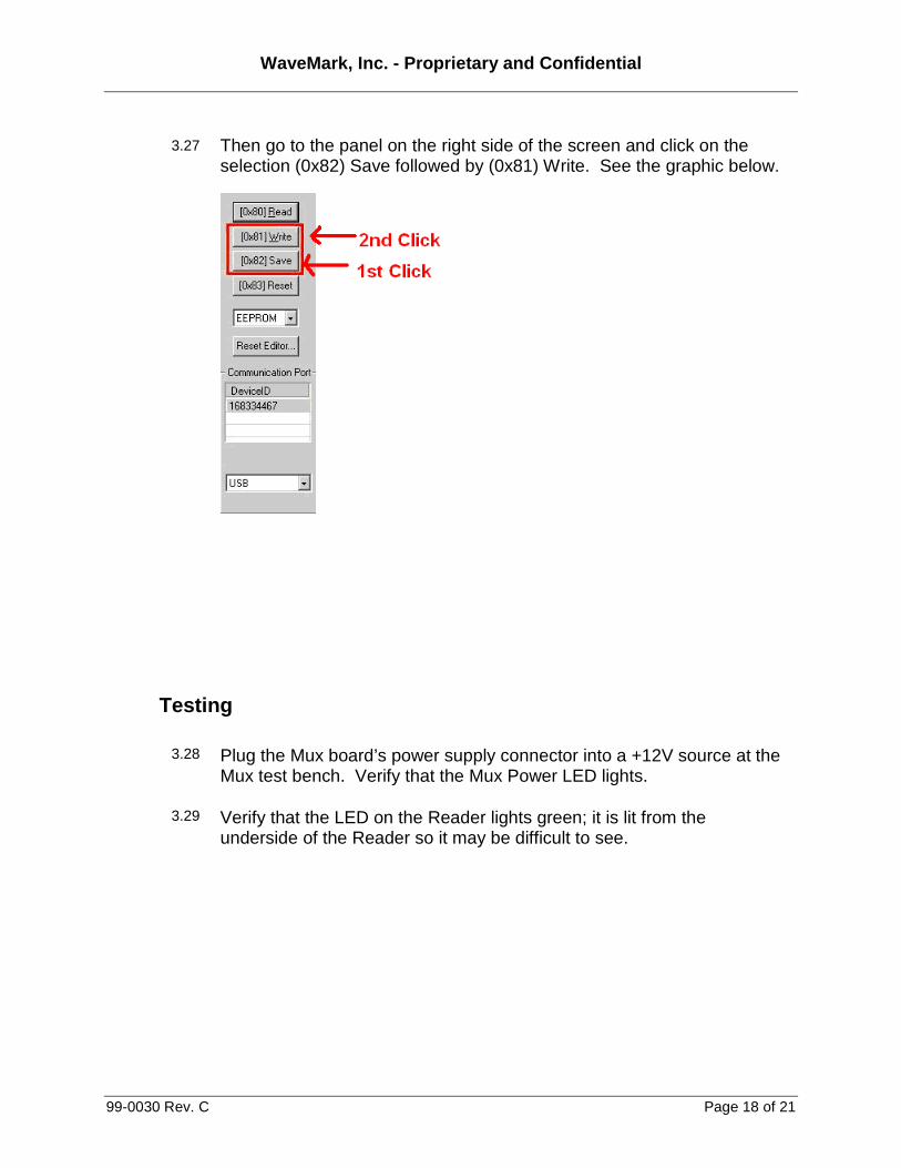
3.27 Then go to the panel on the right side of the screen and click on the selection (0x82) Save followed by (0x81) Write. See the graphic below.
Testing
3.28 Plug the Mux board’s power supply connector into a +12V source at the Mux test bench. Verify that the Mux Power LED lights.
3.29 Verify that the LED on the Reader lights green; it is lit from the underside of the Reader so it may be difficult to see.
WaveMark, Inc. - Proprietary and Confidential
99-0030 Rev. C Page 19 of 21
Labeling
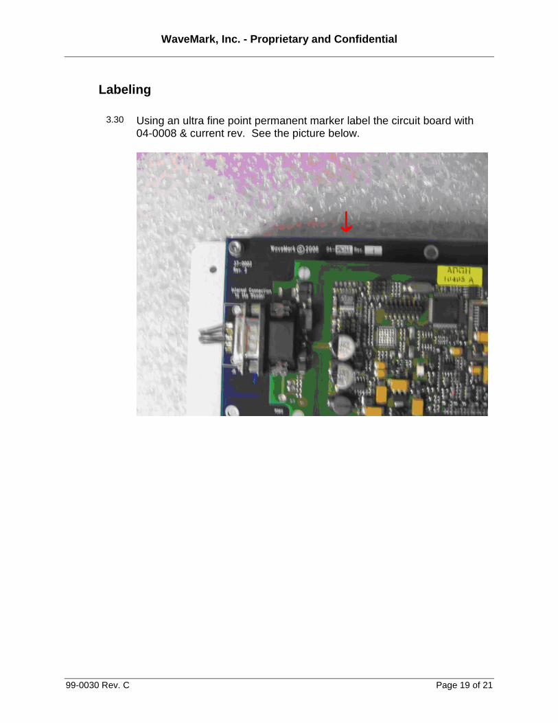
3.30 Using an ultra fine point permanent marker label the circuit board with 04-0008 & current rev. See the picture below.
WaveMark, Inc. - Proprietary and Confidential
99-0030 Rev. C Page 20 of 21
4. Assembling the Mux RF to Data Assembly - P/N 03-0004
Pick List
To assemble, pick the following part number/quantities from inventory. When building more than one, scale the values accordingly.
Qty P/N Part Name
( ) _____ 1 04-0008 Mux/Reader Assembly (from previous step)
( ) _____ 2 38-0001 Cable, 9-pin D-sub M-F Straight Thru 2.5 feet
( ) _____ 1 38-0004 Cable, PC Power Cable Extender, 12 inches
( ) _____ 1 38-0007 Cable, Motor to Mux Board
( ) _____ 1 41-0006 Ferrite Core, snap on, .350 inch box
( ) _____ 2 41-0005 Ferrite Core, snap-on, 13.00mm
( ) _____ 12’’ 86-0005 Cable Wrap, Heli-Tube
Tools and Test Equipment Required
Nut drivers: 3/16, 1/4, 5/16, 11/32
Wire cutters, small
Assembly
4.1 Select the Mux/Reader Assembly (04-0008).
4.2 Select one Motor to Mux Board cable (38-0007) and one Ferrite Core (41-0006). Loop the Motor to Mux board cable through the Ferrite Core, approximately 3 ½’’ from end of the cable. Plug the end near the Ferrite Core into the Mux Board connector labeled Subnet Port 2 located at J5.
4.3 Select a PC Power Cable Extender (38-0004) from inventory and select the roll of Heli-Tube (86-0005). Cut a piece of Heli-Tube about 12 inches long and wrap the Heli-Tube around the PC Power Cable Extender wires.
WaveMark, Inc. - Proprietary and Confidential
99-0030 Rev. C Page 21 of 21
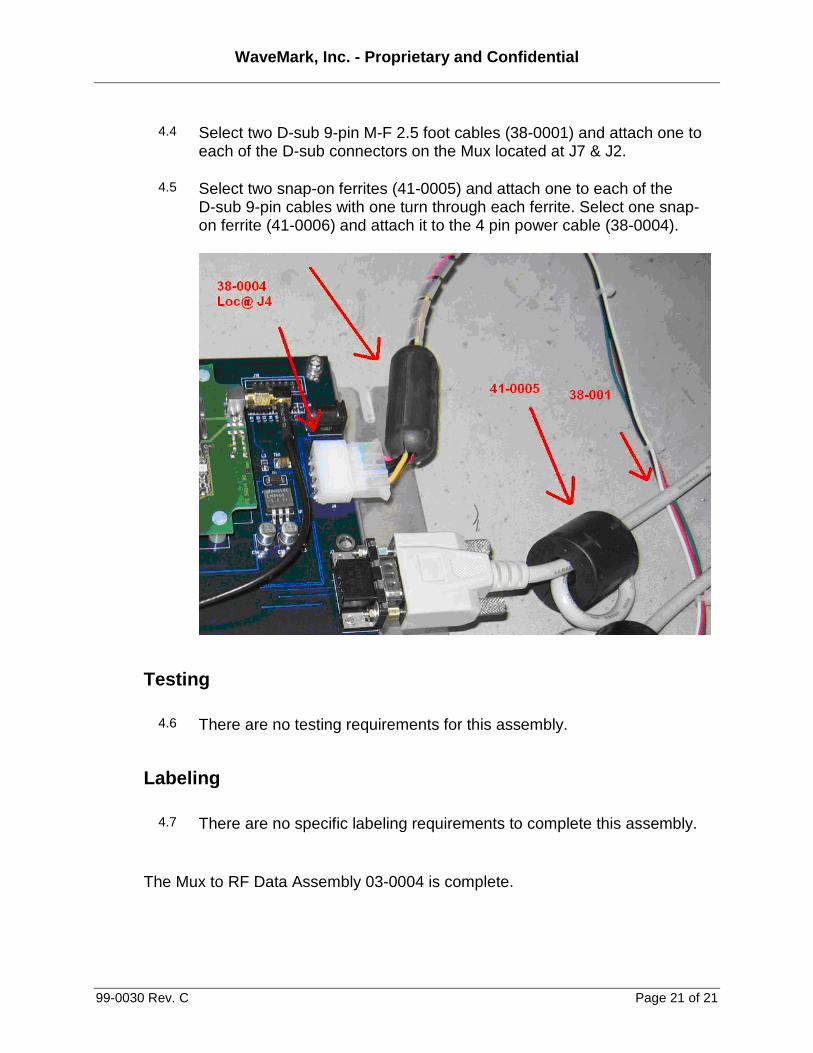
4.4 Select two D-sub 9-pin M-F 2.5 foot cables (38-0001) and attach one to each of the D-sub connectors on the Mux located at J7 & J2.
4.5 Select two snap-on ferrites (41-0005) and attach one to each of the D-sub 9-pin cables with one turn through each ferrite. Select one snap-on ferrite (41-0006) and attach it to the 4 pin power cable (38-0004).
Testing
4.6 There are no testing requirements for this assembly.
Labeling
4.7 There are no specific labeling requirements to complete this assembly.
The Mux to RF Data Assembly 03-0004 is complete.