Embed Size (px)
Citation preview

Proposal for WTOPI Research Consortium Phase III
Wavelet Transform On Propagation and Imaging
for Seismic Exploration
Phase III: Beamlet Migration and the applications
Ru-Shan Wu, Xiao-Bi Xie, and Xian-Yun Wu Modeling and Imaging Laboratory, University of California, Santa Cruz
December, 2002
Objective The objective of the WTOPI Research Consortium is to develop the theory and algorithms of wave propagation and imaging in the wavelet domain for direct application to depth migration and migration velocity analysis. We will strive to find optimum algorithms for both compression and imaging. Based on the theoretical and methodological progress on beamlet propagation and migration in Phases I and II of the WTOPI Research Consortium, the emphasis in Phase III will be put on the application oriented research of migration/imaging in beamlet domain. We will extend the applications to illumination and acquisition-aperture efficacy analysis/correction for best imaging quality, amplitude correction in angle-domain for true-amplitude, true-reflection imaging, velocity updating for wave theory based imaging. We will also put fast elastic wave modeling and multi-dimensional wavelet transform into the research agenda of Phase III.
Background and Approaches Processing huge seismic data sets has become of critical importance to the oil and gas industry in order to obtain high-resolution, high-fidelity images of target areas beneath increasingly complicated structures. Since the current commercial Kirchoff migration method has serious drawbacks for the case of 3-D prestack migration, such as the resolution limitation imposed by the Fresnel radius, multi-arrival interference, and difficulty in preserving true amplitude, there is urgent need in the oil/gas industry for wave equation based methods to overcome the limitations. The traditional f-x domain finite difference approach also has some intrinsic difficulties, especially for 3-D imaging. One is the grid dispersion problem, which will cause errors and artifacts. The suppression of these nuisances usually leads to severe attenuation of large-angle waves which are important for imaging steep structures. Other problems of the finite difference approach include the numerical anisotropy for 3-D geometry and difficulty in midpoint-offset domain formulation. The newly developed fast wavelet transform (WT) is considered to be a revolutionary breakthrough in signal analysis/processing. In the same time frame, there has been significant progress in one-way wave propagation theory and algorithms, including the recently developed multi-domain techniques, such as the fast acoustic and elastic generalized screen propagators and their applications to imaging by our group (See our Technical Report "Modeling and Imaging Project", No. 1-9). We propose to apply the wavelet
1

transform to the generalized screen or other one-way wave propagation methods to develop efficient 3-D high-resolution/high-fidelity imaging methods. The cross-breeding of these two new developments has the potential of revolutionizing modeling and imaging techniques for complex Earth media. Wavelet Transform and Beamlet Migration During Phase I of the WTOPI Research Consortium, we have done a thorough study of propagator decomposition by wavelet transform (WT), including the standard WT, WPT (wavelet-packet transform) and adaptive WPT, LCT (local cosine transform) and Adaptive LCT, WFT (windowed Fourier transform) and GDF (Gabor-Daubechies frame), and specially constructed wavelets, such as the physical wavelets (acoustic wavelets). For beamlet migration in laterally heterogeneous media, we have successfully explored an approach of local perturbation theory in Phase I (Wu, Wang and Gao, 2000). We adopt the local cosine basis (LCB) for the orthogonal decomposition and the Gabor-Daubechies Frame (GDF) for the non-orthogonal decomposition. The LCB decomposition is orthogonal and therefore efficient. However, due to the symmetric property of the basis function, the direction is not totally localized. On the other hand, GDF decomposition has good directional localization but is less efficient than LCB beamlets. Although GDF is not orthogonal, the tight frame decomposition we used is still much more efficient than windowed Fourier transform. For migration/imaging in heterogeneous media, we have made significant progress in Phase II. We successfully developed the theory, methods and algorithms for beamlet migration using LCB and GDF beamlets. Fig. 1 and 2 show the results of 2D beamlet migration for the SEG/EAGE salt model and Marmousi model, respectively. By comparison with the results from split-step Fourier method, we see the high quality of beamlet imaging. Fig. 3 shows the results (two vertical slices) of 3D poststack migration for SEG/EAGE salt model. The high image qaulity of salt boundaries and subsalt structures can be seen clearly. In addition to the high quality of final image, beamlet migration has some special features which distinguished it from other methods: imaging in beamlet domain (space-angle domain) so that DI (Directional Illumination) and AAE (Acquisition-Aperture Efficacy) mappings can be performed directly. Beamlet method will give us the optimal space-direction localizations satisfying the Heisenberg uncertainty principle for wave phenomena. In contrast, the illumination mapping by ray-theory does not satisfy the Heisenberg principle and therefore may not represent the reality. As an example we show the illumination map album of SEG/EAGE salt model for different local directions in Fig. 4. We see that the oblique illumination maps (±30 degrees and ±45 degrees) are quite different from the vertical or total illuminations. The shadow zones under the salt body for right-to-left oblique illumination can be seen clearly, but not for other directions. In order to map the total efficacy of the acquisition system including the receiver-aperture effects for all the shots, we define and calculate the local AAE (Acquisition Aperture Efficacy) matrices (Fig 5) for the image space or for specific target points. The AAE matrix A quantifies the system response for each pair of local incident-scattering angles (Fig. 5). Fig. 6 shows the AAE matrices for 4 target points. We see that for the point outside the shadow of the salt-body (point P1), the AAE has nearly a uniform distribution. However, for the target points under the salt body (P2, P3, P4), the AAE matrices are quite nonuniform. Especially for P2 and P4, the corresponding AAE matrices indicated that the system responses at the two points are favorable to reflectors with opposite dip directions. To simplify the AAE representation, we assume the scatterer at each point to be a plane reflector with different dips. The AAE reduces to acquisition dip response (ADR) which is only a function of dip-angle at each point. Fig. 7 gives the album of ADR for acquisition system of data synthesis for the SEG/EAGE salt model. We see the
),( scin θθ
2

dramatic differences between the ADR for different dip-angles, especially for the subsalt regions. These can well explain the image strengths for different structures of the prestack depth migration. Fig. 8 gives the image of beamlet migration with emphasis on subsalt structures, together with the total illumination map and total ADR map. We see that the total ADR itself can not relate the image strength with the total acquisition efficacy very well. In contrast, we give the directional ADR maps in Fig. 9 which has good correlation with the image quality (strength) of reflectors of different dips. Note that the steep-fault in the middle of the model has very weak system response, especially for the upper-half. This explains the weak image of the fault and the total absence of its upper half. The left steep-fault has even weaker system response (ADR). However, its reflection coefficient is 2.5 times larger than the middle one, so it got better imaged. After obtaining the DI and AAE (or ADR), we can perform various amplitude corrections to improve the image quality and conduct local AVA (amplitude vs. angle) analysis or local inversion for medium parameters. These will be the research objects of our WTOPI-III Research Consortium. Fig. 10 gives an example of amplitude correction. We see that after the preliminary corrections, the images for the subsalt steep faults become stronger.
Research Tasks for WTOPI-Phase III 1. Beamlet Propagation, Migration/Imaging One important task is to improve the accuracy and efficiency of beamlet propagation, especially for the 3D cases. We will search for numerical methods sparsifying the propagator matrices and speed up the sparse-matrix operations. In addition, we will develop asymptotic theory for beamlet propagation in smoothly varying regions of the media. 3D prestack depth migration will be implemented with the improved fast-speed beamlet propagators. Parallelization will be introduced to the migration algorithm. We will also improve the accuracy of perturbation correction for beamlet propagator to further increase the imaging quality, especially for subsalt structures. 2. DI (Directional Illumination) and AEE (Acquisition Aperture Efficacy) Analysis and Mapping We have successfully applied the theory and methods to the 2D synthetic models. The next step is to develop and test the methods for the 3D cases. Technical problems such as memory allocation need to be solved for 3D implementations. 3. Amplitude Correction in Angle-Domain and True-Amplitude, True-Reflection Imaging Beamlet propagators are based on wave theory and operate in local phase-space. True-amplitude and true-reflection imaging can be achieved by performing illumination and acquisition-aperture analysis and corrections in local phase-space. That will be a major task of the Phase III In addition to imaging, we will conduct some preliminary study on local AVA and local inversion before stacking for final images. 4. Velocity updating for wave-theory based methods
3

Although conventional velocity analysis methods, such as the moveout residual analysis and focusing analysis, may be adapted for wave-theory based methods, such as the generalized screen propagators (GSP) and beamlet propagators, or finite difference propagators, we will, however, put emphasis on the development of wave-theory based method, such as diffraction tomography, specially tailored for our purpose. Some work has been started in Phase II. More effort will be put on this in Phase III. 5. Multi-Dimensional Time-Space Wavelet Transform Applied to Wave Propagation and Imaging This is the ultimate goal of the WTOPI Research Consortium. Although Phase III will put our major effort on the extension and application of our developments in theory and methods of beamlet imaging we achieved in Phases I and II, we will nevertheless put some effort on the theory and method of multi-dimensional time-space wavelet theory. We plan to develop the basic theory in collaboration with mathematicians in this field exploring the true potential of imaging in multi-dimensional wavelet domain.
Other Research Topics in MILAB Related to the WTOPI Consortium Fast Elastic Wave Modeling
Fast elastic wave modeling can help the analysis and processing for real field data sets. It is an important tool for improving imaging quality and interpretation. We have developed fast modeling methods (Thin-slab method and Complex-screen method) based on the De Wolf approximation, with computation speed 2-3 orders of magnitude faster than finite-difference (FD) and finite-element methods. Fig. 11 gives the synthetic seismograms using our method (solid lines) compared with FD method (dotted lines) for the elastic French model. The results from these two methods agree well in general. However, our method is 60 times faster than the FD method. Fig. 12 gives the AVO responses calculated with our thin-slab method. The model contains random heterogeneities, visco-elastic irregularities and thin-layer structure (thinner than wavelength), very challenging to traditional modeling methods but relatively easy to implement by thin-slab method. Although elastic wave modeling is not a research task of the WTOPI Research Consortium, our members have shown substantial interest to the topic. Therefore we will put some effort to it in Phase III. In conjunction with projects supported by other agencies, we can conduct the study and present the results in our reports and annual meetings without obligation of code distribution.
Research Team
The UCSC seismic Modeling and Imaging Laboratory (two professors, two researchers, four postdoctoral researchers and a few visitors and graduate students) has been recognized as one of the foremost group in the world on one-way wave propagation and imaging. We are teaming up with other collaborators from the industry, professors and researchers in mathematics and signal processing in universities and research institutions. The joint effort of the team will increase significantly the speed of research progress.
4

Sponsorship The Phase III project is designed as a three year project from April 1, 2003 to March 31, 2006, but each sponsor's contribution is renewable in a yearly basis. There are two options to sponsor the WTOPI Research Consortium Phase III: 1) As a “supporting member” of the “Modeling and Imaging Project”, Center of Study for Imaging and Dynamics of the Earth, University of California, contribute a sum of $22,000 as a research gift. Please contact Karen Fry, at the Natural Science Development Office for the agreement. (Tel: 831-459-1522; Fax: 831-459-5237; Email: [email protected]) (2) As a WTOPI “Consortium member” contribute $31,800 with a formal consortium agreement. A sample agreement is attached for your reference. To sign an agreement, please contact Kate Aja at the “Office of Sponsored Projects” of the University of California at Santa Cruz. (Tel: 831-459-3341; Fax: 831-459-4989; Email: [email protected]) For new members who have not contributed to the Phase I or II researches, an entry fee is required in the amount of $30,000 which can be paid over three years. For special cases, terms of entry can be negotiated. WTOPI Research Consortium will have annual meetings in April, presenting our research results, and distributing technical reports and computer codes to our members. Short-term visits to our laboratory can be arranged upon request.
References UCSC Modeling and Imaging Project, Technical reports No. 1-9, (1996-2002). Chen, L. and Wu, R.S., 2002, Target-oriented prestack beamlet migration using Gabor-Daubechies frames, Expanded abstracts, SEG 72nd Annual Meeting, 1356-1359. Foster, D.J., Wu, R.S. and Mosher, C.C., 2002, Coherent-state solutions of the wave equation, Expanded abstracts, SEG 72nd Annual Meeting, 1348-1351. Mosher, C.C., Wu, R.S. and Foster, D.J., 2002, Phase shift migration using orthogonal beamlet transforms, Expanded abstracts, SEG 72nd Annual Meeting, 1332-1335. Wang, Y. and Wu, R.S., 2002, Beamlet prestack depth migration using local cosine basis propagator, Expanded abstracts, SEG 72nd Annual Meeting, 1340-1343. Wu, R.S. and Chen, L., 2002, Mapping directional illumination and acquisition-aperture efficacy by beamlet ropagators Expanded abstracts, SEG 72nd Annual Meeting, 1352-1355. Wu, R.S., Chen, L. and Wang, Y., 2002, Synthetic beam-sources and plane-sources for prestack beamlet migration, Expanded abstracts, SEG 72nd Annual Meeting, 1336-1339. Xie, X.B. and Wu, R.S., 2002, Extracting angle related image from migrated wavefield, Expanded abstracts, SEG 72nd Annual Meeting, 1360-1363.
5

Wu, R.S. and Chen, L., 2002, Wave propagation and imaging using Gabor-Daubechies beamlets, "Theoretical and Computational Acoustics" , World Scientific, New Jersey, 661-670. Wu, R.S., Chen, L. and Wang, Y., 2002, Prestack migration/imaging using synthetic beam-sources and plane-sources, Special issue of "Studia Geoph. et Geod.", in press. Wu, R.S. and Chen, L., 2001, Beamlet migration using Gabor-Daubechies frame propagator, Extended Abstracts, EAGE 63rd Annual Meeting, P074. Wu, X.Y. and Wu, R.S., 2001, AVO modeling using one-return approximation, Expanded abstracts, SEG 71st Annual Meeting, 312-315. Xie, X.B. and Wu, R.S., 2001, Modeling elastic wave forward propagation reflection using the complex screen method, J. Acoust. Soc. Am., 109, 2629-2535. Wu, X.Y. and Wu, R.S., 1999, Wide-angle thin-slab propagator with phase matching for elastic wave modeling, Expanded abstracts, SEG 69th Annual Meeting, 1867-1870. Xie, X.B. and Wu, R.S., 1999, Improving the wide angle accuracy of the screen propagator for elastic wave propagation, Expanded abstracts, SEG 69th Annual Meeting, 1863-1866. Wu, R.S. and Wang, Y., 1998, Comparison of propagator decomposition in seismic imaging by wavelets, wavelet-packets, and local harmonics, "Mathematical Methods in Geophysical Imaging V", Proc. of SPIE, v. 3453, 163-179. Wu, R.S. and Yang, F., 1997, Seismic imaging in wavelet domain: Decomposition and compression of imaging operator, Wavelet Applications in Signal and Image Processing V, Proc. SPIE, v. 3169, 148-162.
6

(a) SEG/EAGE salt model (a) Marmousi model
(b) Split-step Fourier prestack migration (b) Split-step Fourier prestack migration
(c) G-D beamlet prestack migration (c) G-D beamlet prestack migration
Fig. 2 Beamlet prestack depth migration (Marmousi model)
Fig. 1 Beamlet prestack depth migration
(SEG-EAGE model)
3D GDF beamlet migration
SEG 3D Salt Model (Vertical slice) SEG 3D Salt Model (Vertical slice)
3D LCB beamlet migration
Fig. 3 3D poststack beamlet migration for SEG/EAGE salt model
7

Fig. 4 Illumination album of SEG/EAGE salt model for different local directions.
vertical direction -30° (from vertical to left)
30° (from vertical to right) -45° (from vertical to left)
total illumination intensity 45° (from vertical to right)
8

•⋅⋅⋅•••⋅⋅⋅⋅⋅⋅⋅⋅⋅⋅⋅⋅•⋅⋅⋅••••⋅⋅⋅•••
inθ
scθ
ϑ
),( scinA θθ
S Receiver ou*
rce *
High-velocity body
Target area
Local AAE Matrix: Acquisition aperture efficacy at the target area (including propagation effects of the overlaying structures)
Fig. 5 Local AAE (acquisition aperture efficacy) matrix.
2D SEG- EAGE model
P1 P2 P3 P4
left-side 176 receivers per shot (total 325 shots)
Fig. 6 Local AAE matrices for planar reflectors at different locations:
P1 (outside salt body), P2, P3, P4 (subsalt locations).
9

+30° (down from horizontal) horizontal
+45° (down from horizontal) -30° (up from horizontal)
total response intensity -45° (up from horizontal)
Fig. 7 Album of ADR (Acquisition-Dip-Response) for the acquisition system of data synthesis for SEG/EAGE salt
model. The dip-angles of reflector are defined as angles down from positive X-axis clockwise.
10
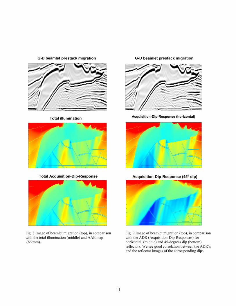
G-D beamlet prestack migration
Acquisition-Dip-Response (horizontal)
Acquisition-Dip-Response (45°
G-D beamlet prestack migration
Total illumination
Total Acquisition-Dip-Response dip)
Fig. 8 Image of beamlet migration (top), in comparison Fig. 9 Image of beamlet migration (top), in comparison with the total illumination (middle) and AAE map with the ADR (Acquisition-Dip-Responses) for (bottom). horizontal (middle) and 45-degrees dip (bottom) reflectors. We see good correlation between the ADR’s and the reflector images of the corresponding dips.
11

12
Fig. 10 The images for the subsalt steep faults become stronger after the preliminary corrections in angle-domain.
G-D beamlet prestack migration image
Improved image after directional illumination correction
Acquisition-dip response for 45o reflectors

Fig. 11 Synthetic seismograms for French model (top) using the thin-slab method. For this example, the thin-slab method is about 60 times faster than finite-difference method.
13

Fig. 12 AVO modeling for visco-elastic, heterogeneous reservoirs (oil or gas sand model). Q and are the quality
factors of P and S waves of shale layer, respectively, and Q and Q are the quality factors of P and S waves of oil or gas sand layer.
0P
0SQ
P S
14