Embed Size (px)
Citation preview
0OWFSCWAVEFRONT SENSING & CONTROL GROUP
Status on Iterative Transform Phase Retrievalapplied to the GBT Data
Bruce Dean 1551, David Aronstein / 551, Scott Smith /551, Ron Shiri 1551Jan M. Hollis / Lyon / 606.3
Richard rests e, Todd Hunter, Frank Ghigo, Bojan N1 i
Image-Based Wavefront Sensing and Control of the NRAOGreen Bank Radio Telescope
NASA PI: Dr. Bruce H. Dean 1551Email: [email protected]: Dr. Jan M. Hollis 1606.0, Richard Lyon /606.3,
Ron Shiri /551, Scott Smith /551, David Aronstein /551Collaborators: Dr. Richard Prestage I Assistant Director, National Radio
Astronomy Observatory (NRAO) Green Bank Operations, GreenBank, WV, Todd Hunter, Frank Ghigo, NRAO Green BankOperations, Can Bank, WV, Bojan Nikolic, Mullard RadioAstronomy Observatory, Universiy of Cambridge, UK
Business Area: Astrophysics, Communications I Navigation Systems, ExplorationSystems.
https://ntrs.nasa.gov/search.jsp?R=20090033811 2020-04-09T16:17:13+00:00Z
Overview 0
Introduction- Phase Retrieval /NASA Projects— JWST TRL-6
GBT Data / Notes:— Data Format and Sampling- Ray Trace Model & Wavefront— Symmetry of GBT Data— Pupil and Fourier Model— Pupil Amplitude
PR Simulations— Wavefront derived from GBT Data symmetry— Wavefront Sensing accuracy and Coherent
AssumptionsGBT Results
/ Incoherent
2
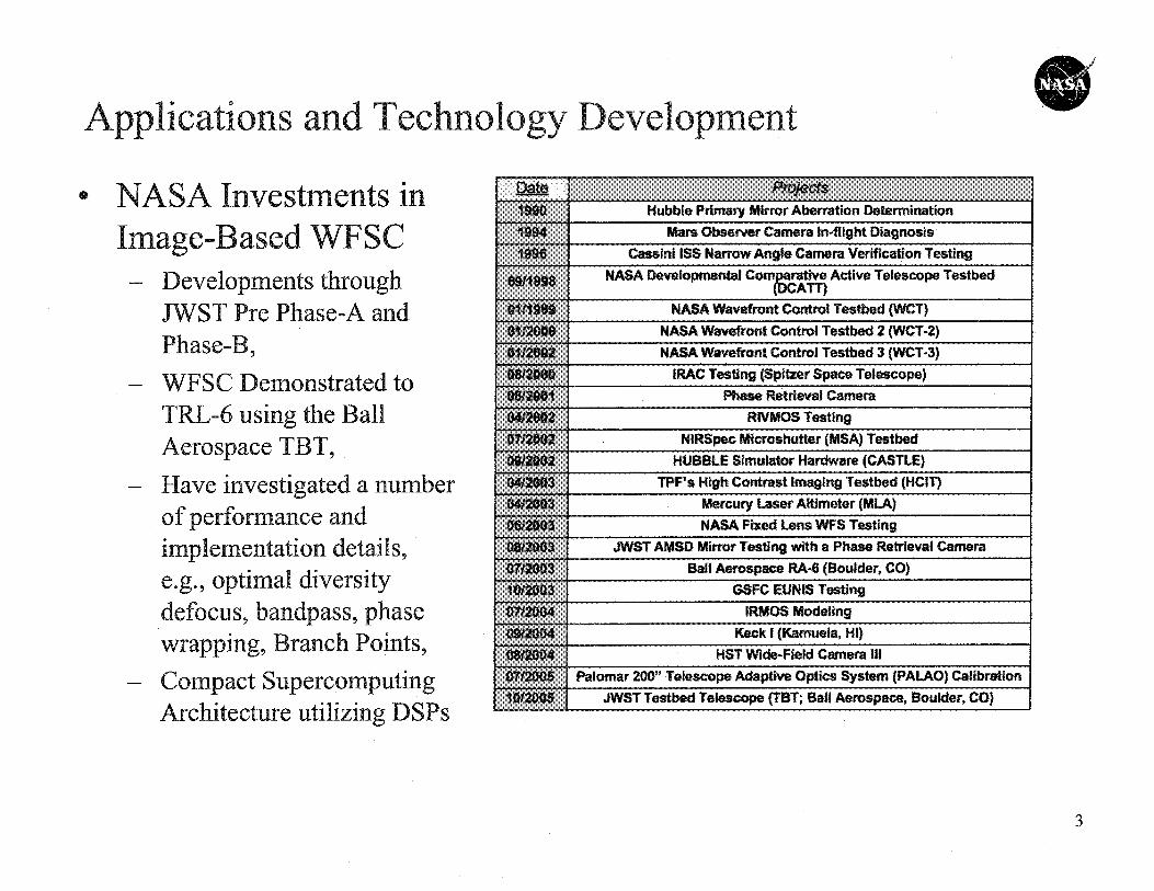
Applications and Technology Development
Investments9 NASA Image-Based— Developments through
JWST PrePhase-A anPhase-B.
C Demonstrated toTRL-6 using the BallAerospace TBT,
— Compact SupercomputingArchitecture utilizing DSPs
3
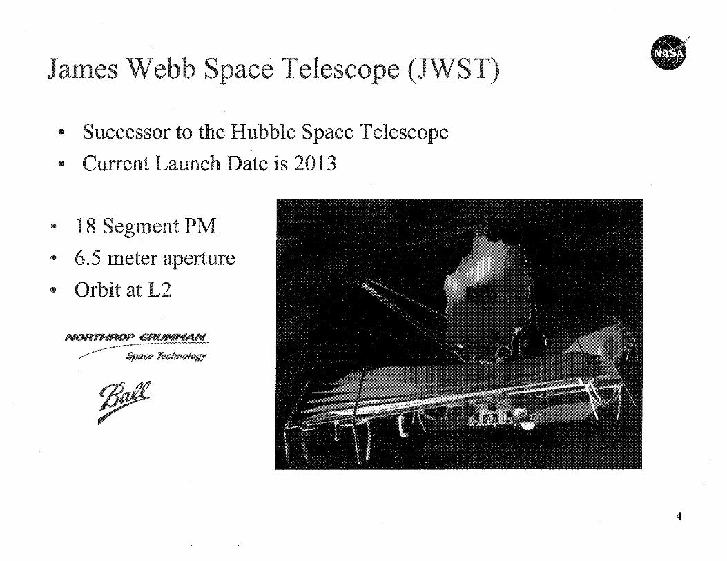
0 18 Segment PM0 6.5 meter aperture
* Orbit at L2
sfiwce rechnaloff
PX
James Webb Space Telescope (JWST)
• Successor to the Hubble Space Telescope
• Current Launch Dateis 2013
4
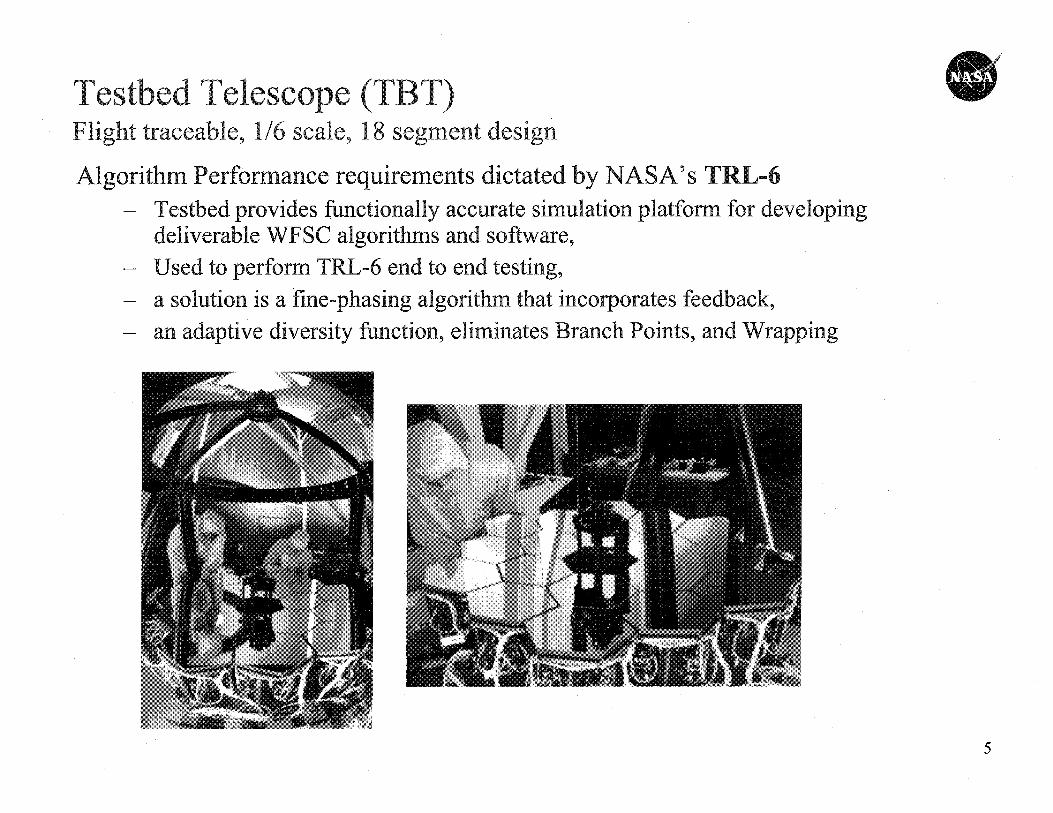
S'Testbed Telescope (TBT)Flight traceable, 1/6 scale, 1. 8 segment design
Algorithm Performance requirements dictated by NASA's TRL-6— Testbed provides functionally accurate simulation platform for developing
deliverable WFSC algorithms and software,— Used to perform TRL-6 end to end testing,— a solution is a fine-phasing algorithm that incorporates feedback,— an adaptive diversity function, eliminates Branch Points, and Wrapping
5
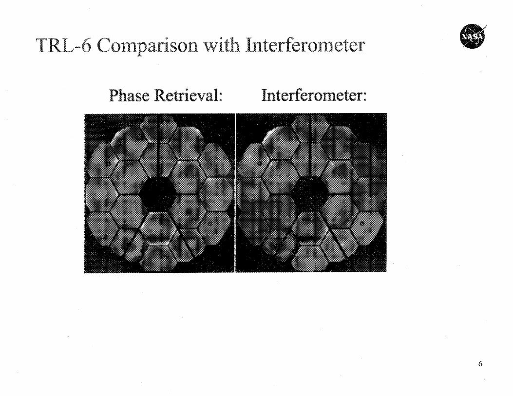
0TRL-6 C with Interferometer
Phase Retrieval: 0 y'
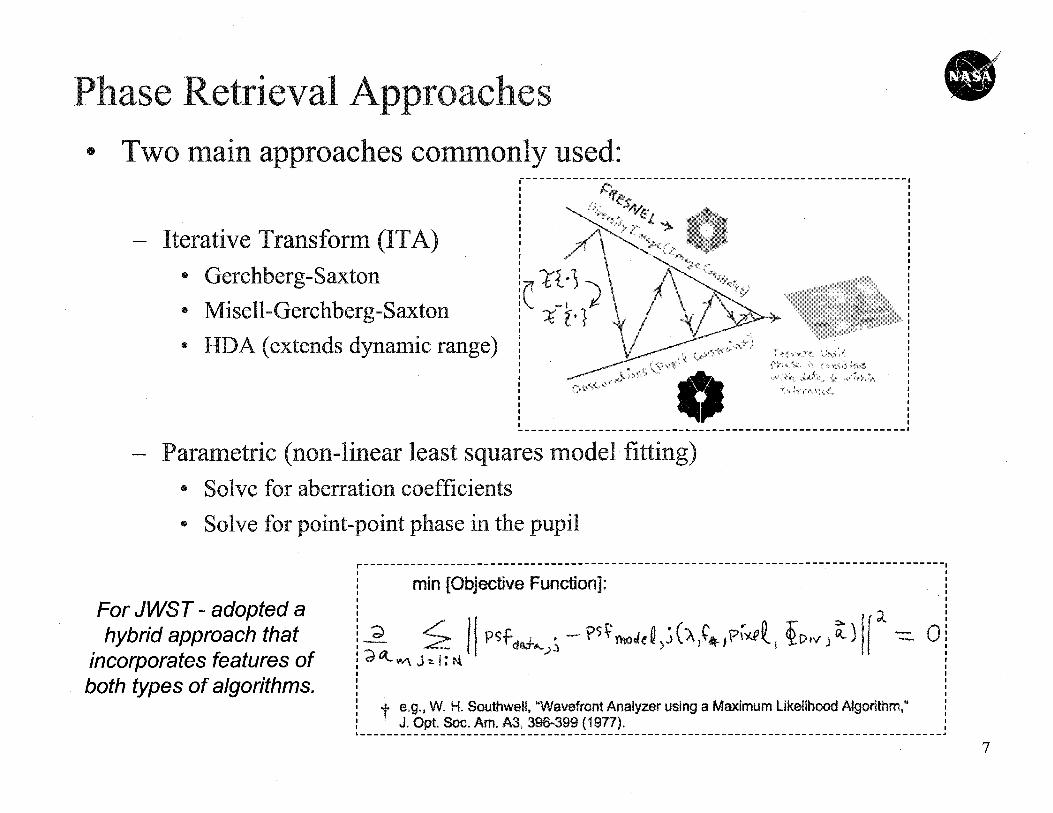
0Phase Retrieval Approaches
Two main approaches commonly used:---------------------------------------------------------
VA
"mow
W^ AANIFAm
--------------------------------------------------
— Iterative Transform (IA)
• Gerchberg-Saxton
• Misell-Gerchberg-Saxton
• HDA (extends dynamic range)
— Parametric (non-linear least squares model fitting)
• Solve for aberration coefficients
• Solve for point-point phase in the pupil
r---------------------------------------------------------------------------------------
min [Objective Function]:
For JWST - adopted a0hybrid approach that P S
fft+l')twde^ (_A '^k' F, jD ►V J
incorporates features of
both types of algorithms.t e.g., W. H. Southwell, "Wavefront Analyzer using a Maximum Likelihood Algorithm,"
J, Opt. Soc. Am. A3, 39&399 (1977).------------------------------------------------------------------------------
a
look ==>
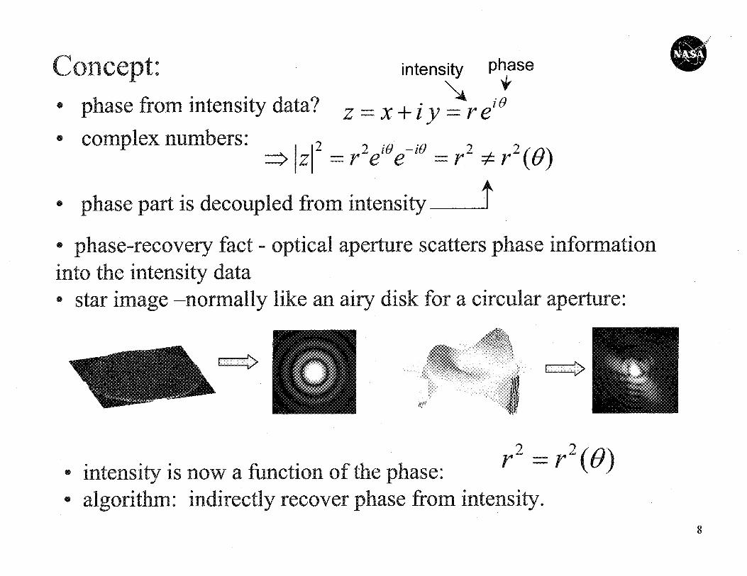
• intensity is now a function of the phase:r2 __
r2 (e)
• algorithm: indirectly recover phase from intensity.
V
s
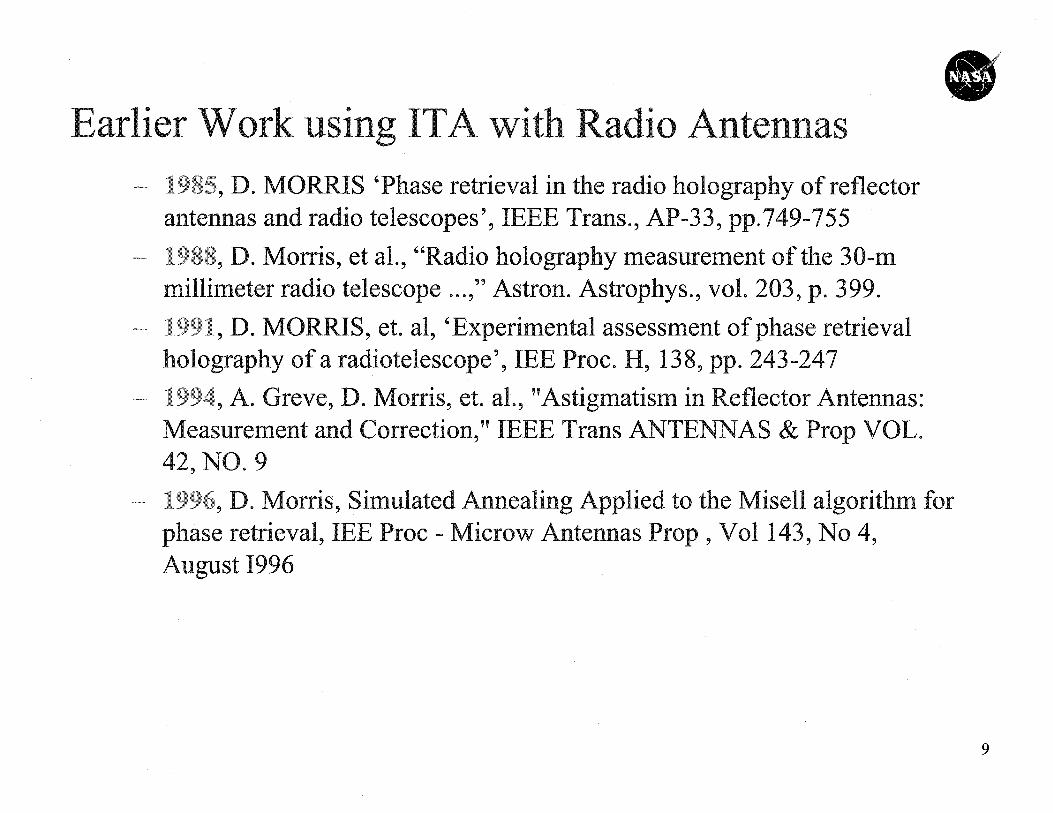
0Earlier Work using ITA with Radio Antennas
1985 D. MORRIS 'Phase retrieval in the radio holography of reflectorantennas and radio telescopes', IEEE Trans., AP-33, pp.749-7551988 5 D. Morris, et al., "Radio holography measurement oft e 30-mmillimeter radio telescope...," Astro strophys., vol. 203, p. 3 99.1.991 5 D. MORRIS, et. al, 'Experimental assessment of phase retrievalholography of a radiotelescope', IEE Proc. H, 1 243-2471994 5 A. Greve, D. Morris, et. al., "Astigmatism in Reflector Antennas:Measurement and Correction," IEEE Trans ANTENNAS & Prop VOL.42 5 NO. 91996 9 D. Morris, Simulated Annealing Applied to the Misell algorithm forphase retrieval, IEE Proc - Microw Antennas Prop, Vol 1 4,August 1996
Notes /Understanding of GBT Data 0
• Consists of two feeds (pixels), two polarizations,
• Separated by 58 arc-seconds,
• Output of receivers is differenced to minimize the effect of sky-brightness variations.
— aberrations due . to of oft feeds being off (and on opposite sides of)the optical axis are negligible?if this is not negligible, then a "single beam convolved by two deltafunctions" assumption may not be valid.
10
i
C
OCU
W
.0 ............ :-,_ .._.-.-rr.--: ..^...__..._,..
.................. . ....... ......... ..,,_._ ._. _. _..
cam_
C
0.15
O.f
^t
°O.PS
-IJ t
-0, 15
azimuth (arc-min)
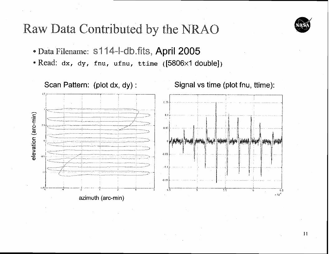
Raw Data Contributed by the NRAO
0
Data iena e: S1 14-1-db.fits, April 2005Read: dx, dy, fnu, ufnu, ttime ( [5806x1 double] )
Scan Pattern: (plot dx, dy)
Signal vs time (plot fnu, ttime):
11
to 20 10 40 so 60
5
10
3S
Two Options:
down-samplein x:
:171x 68`------ 1
90 x : 35 f------- j
in
up-sample
in y:
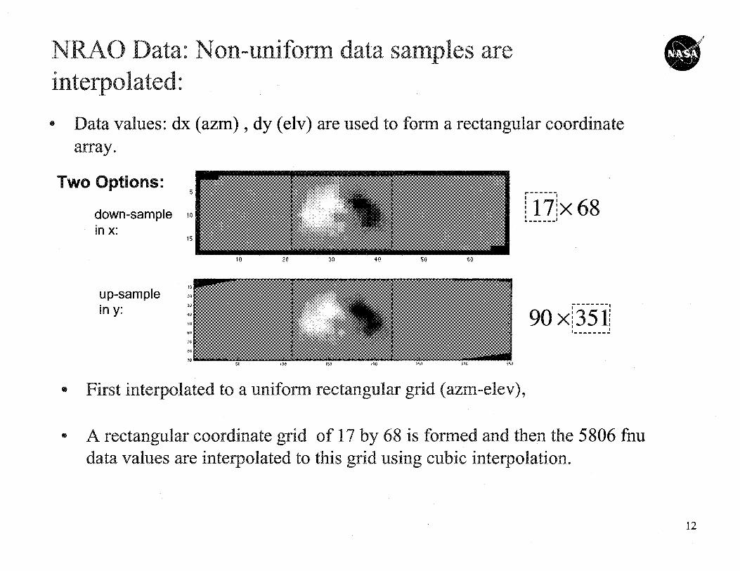
NRAO Data.- Non-uniform data samples areinterpolated-.
0 Data values: dx (azm) , dy (elv) are used to form a rectangular coordinatearray.
0 First interpolated to a uniform rectangular grid (azm-elev),
• A rectangular coordinate grid of 17 by 68 is formed and then the 5806 fhudata values are interpolated tothis grid using cubic interpolation.
12
NRAO Data & Sampling . 0'M
20 40 60 ao 20 40 so SO 40 60 80
I Ft10 410 31) 40 so 60 71) ?1 10 20 4 17 4 0 so 60 7A du to 20 30 40 so so 70 80
...... 0. 2tt
..... ..-0 2 -------------
0 217 40 80 60 100 L .... .... .....in 20 10 40 50 to 71) 0 40 42
1 1 1
0 2 4 ri 6 0 8 0 100
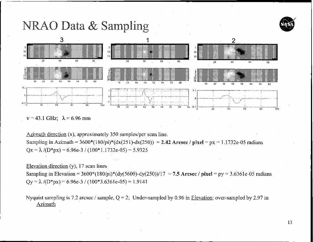
V =: 43.1 GHz; k = 6.96 mm
Azimuth direction (x), approximately 350 samples/per scan line.
Sampling in Azimuth == 3600*( 1 80/pl)*(dx(25 I)-dx(250)) = 2® Arcsec / pixel = px = 1. 1732e-05 radians
Qx =: k /(D*px) = 6.96e-3 / (100* 1. 1732e-05) = 5.9325
Elevation direction (y), 17 scan lines
Sampling in Elevation = 3600*( 180/pi)*(dy(5600)-dy(250)) /17 = 7®5 Aresee / pixel = py = 3.636le-05 radians
Qy = ^ /(I3 * x) = 6.96e-3 / (100 * 3.63 6 1 e-05) = 1.9141
Nyquist sampling is 7.2 arcsec / sample, Q =: 2; Under-sampled by 0.96 in Elevation, over-sampled by 2.97 in
Azimuth
13
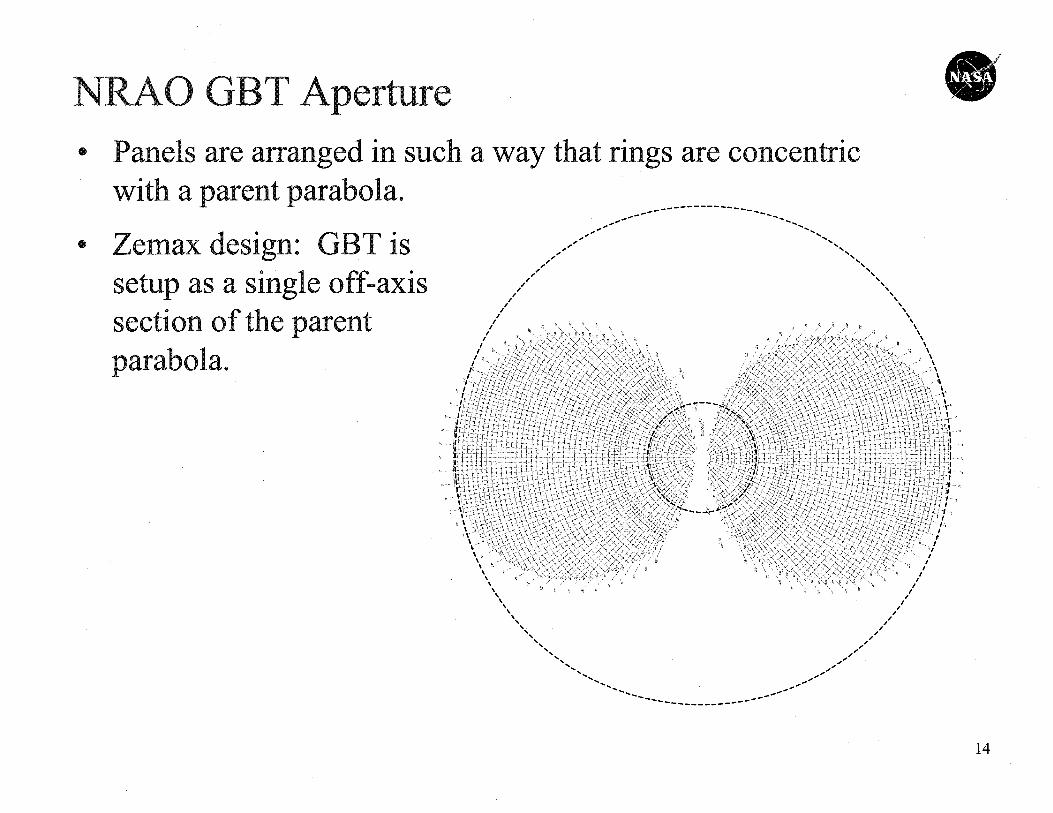
NRAO GBT Aperture 0
ringsPanels are arranged in such a way that
14
S5 o
100
ISO
20
250
o
100
150
00
250
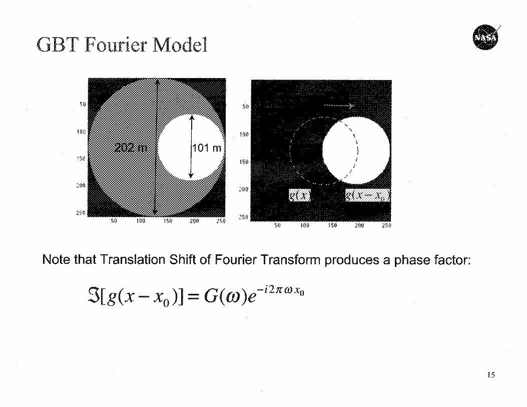
GBT Fourier Model 0
Note that Translation Shift of Fourier Transform produces a phase factor:
'3[g(x - x0 )] - G((t))e—i27r(0xo
15
0
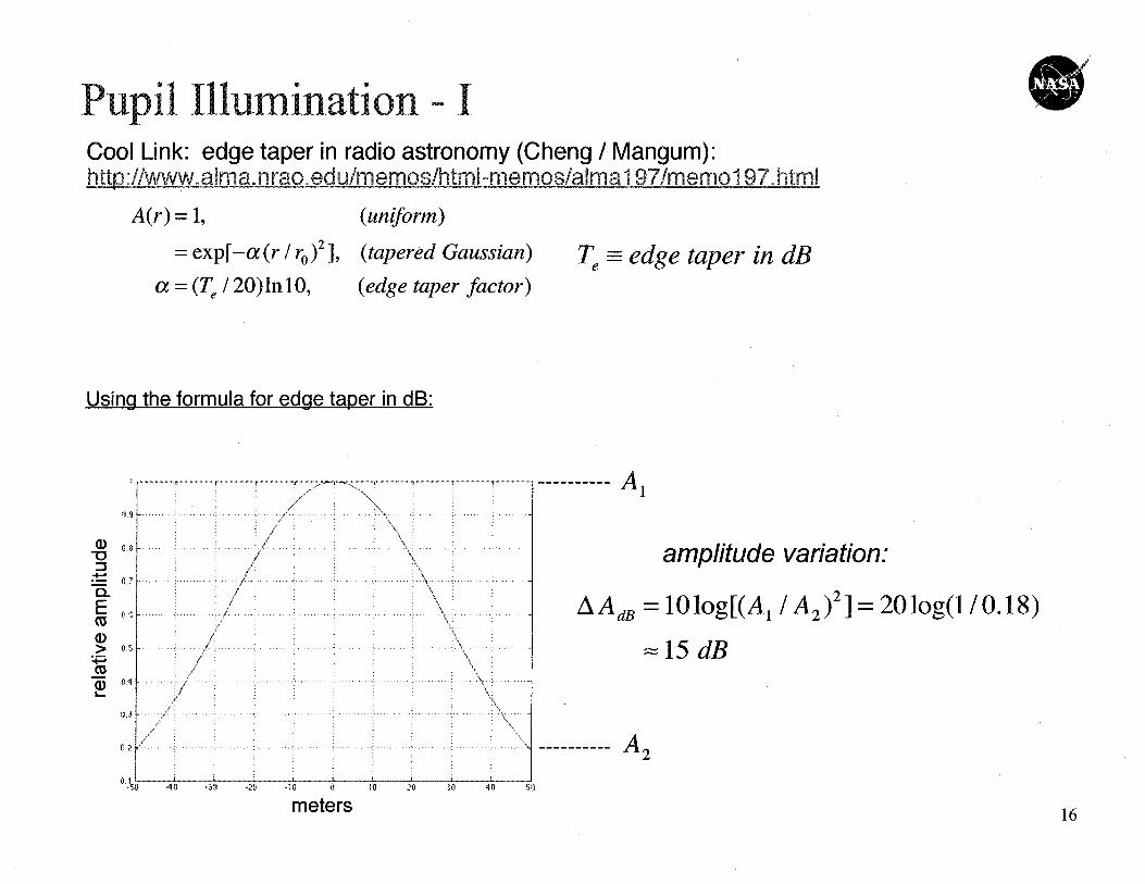
Using the formula for edge taper in dB:
O^
^ a.a
CLQ^
cuW>0A
L0,3
0.2
t
............,r
P' SY
4
---------- Al
amplitude variation:
AA dB = 101og[(A 1 / A 2 )2 ] = 201og(1 /0.18)15 dB
A2"50,
i1i -3p ^20 .11 f+ i6 20 30 4CO Sit
meters16
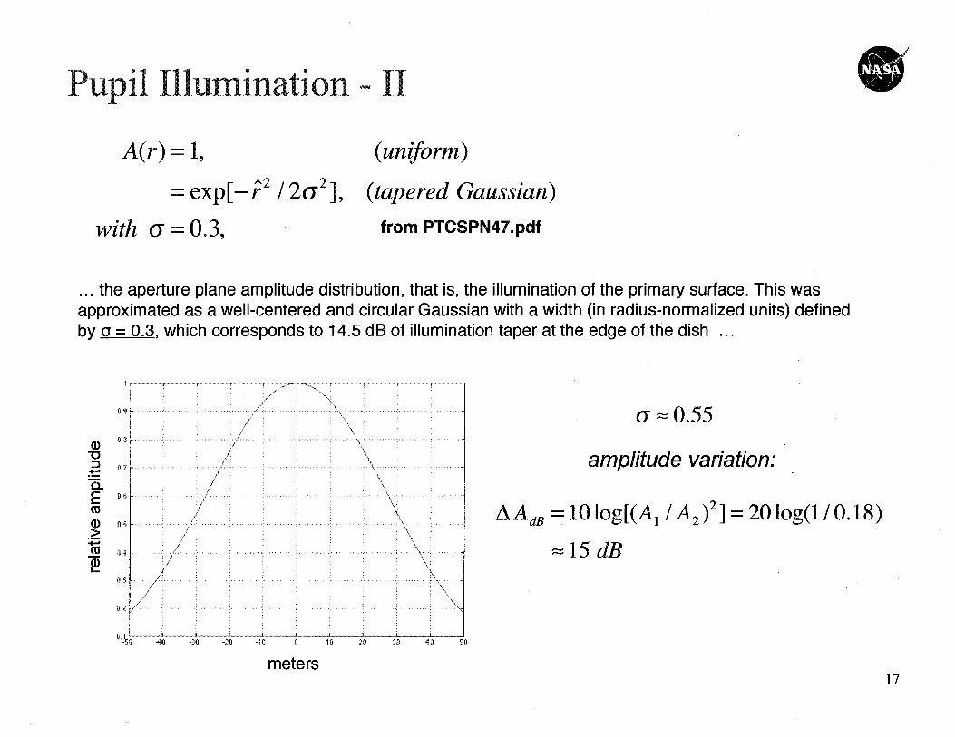
Pupil Illumination - II a'
A(r) =1, (uniform)
-- exp[- r2 /2U2 ], (tapered Gaussian)
with 6 — 0.3 9 from PTCSPN47.pdf
... the aperture plane amplitude distribution, that is, the illumination of the primary surface. This wasapproximated as a well-centered and circular Gaussian with a width (in radius-normalized units) definedby a = 0.3, which corresponds to 14.5 dB of illumination taper at the edge of the dish ...
0
Ccc
0-
r
Y
°^tl
r ` q
f3 Ah _f = it -i 63 h 9i1 M ?A 4n 51
meters
6 = 0.55
amplitude variation:
AAdB =10log[(A 1 / A 2 )2 ] = 20log(1 / 0.18)
15 dB
17
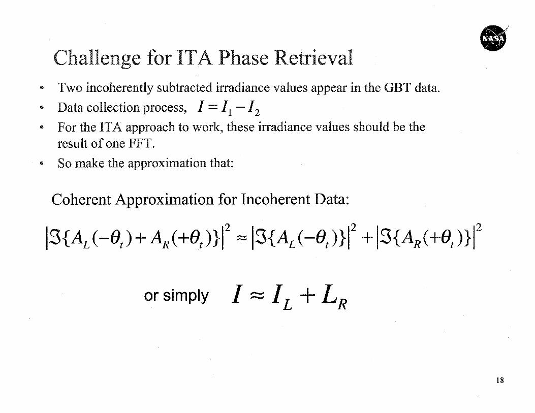
0Challenge for ITA Phase Retrieval
• Two incoherently subtracted irradiance val s appear in e GBT data.
• Data collection process, I — Il —12
• For the ITA approach o work, these irradiance v es should be theresult of one FFT.So make the approximation tat:
Coherent Approximation for Incoherent Data:
1-3fAL(-e,) +AR(+et )} 1 2 - 1scALc-e,>}1z +1sfAR(+e,) }Iz
or simply I-IL+LR
18
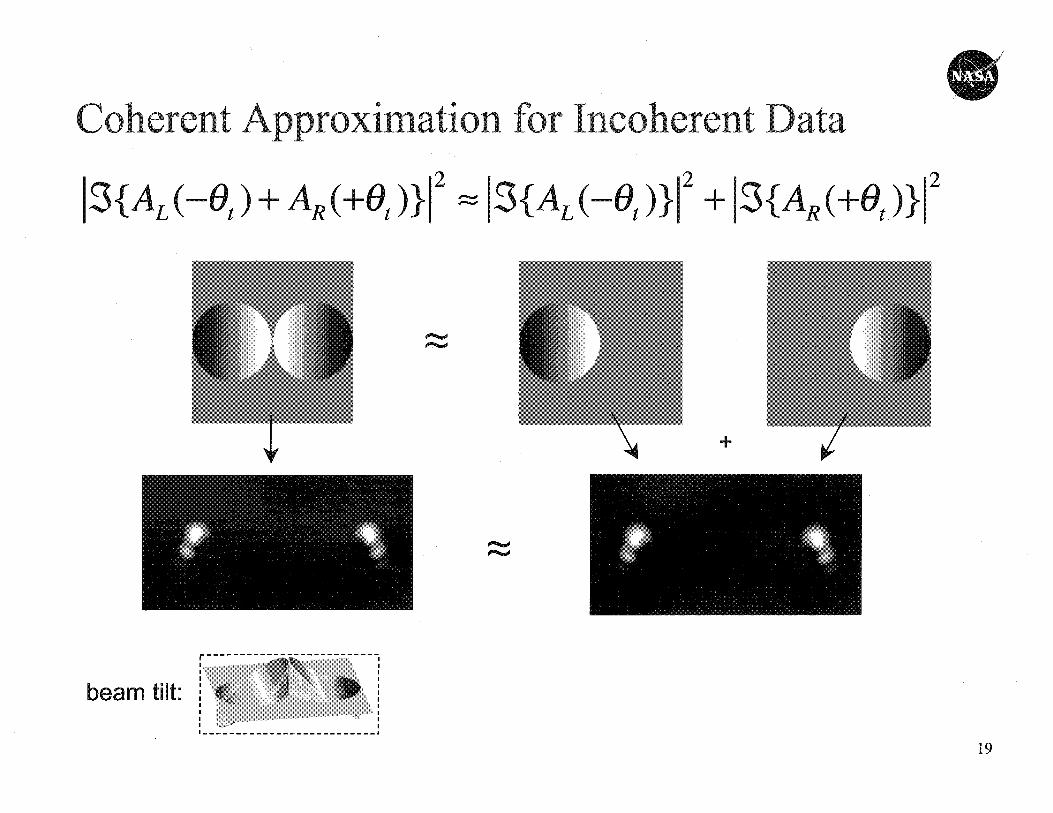
Coherent Approximation for Incoherent Data
3{AL(-B, )+AH(+B,)}Z = 3{A,(-B,)}1Z +13f AR( }B^ ))Z
---------------------------
-------------------------
beam t il t:
19
0
r1l2
I s
1%
Co Co
..........In
In
.... ........ ........ ... .............. . .......... .... .
.... .. ...... ......... .. .......... .......0.5
20
A50 100 150 200
0.2
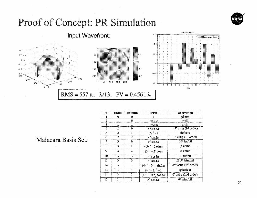
Proof of Concept: PR SimulationInput Wavefront:
DemylpoRionGAS
OA
11.05
0
•05
41 2 3 4 5 6 7 8 9 10 11 12 13 14Two
# d-QW azhnuth tern alieiTation1 0 0 1 piston2 1 0 rsina Y-tilt,3 1 1 r Cosa X -tilt4 2 0 r An 2a 45" astigg (1 91 order)5 2 1 2 r 2 —1 defocus6 2 2 1' 2 sin 2a 01, astig (lot ogler)7 3 0 r 3 sin 3a 3011 trefoil
8 3 1 43r 2) sin a y-coma
9 3 2 ?-(3r2 —2)cosa x-coma
10 F--i 3 r21cos3a 00 trefoil11 1 3 3 r 4 sin4a 22.50 tetrafoil12 3 3 (4r.4 —3r 2)sin2a 450 astig, (210 order)
13 3 3 6r 4 —2r 2 -1 spherical14 3 3 (4r 4 — 3r 2) cos,2a 00 antig (2nd order)
15 3 31 r4 cos4a 00 tetrafbil
Malacara Basis Set:
21
RMS = 557 g; X/13; PV = 0.4561 X
ISO 200 2 5 0 301) 350
Resu lts:jj.15
13.1
.^5
405
Pup il lit
SQ
E(iQ
t5R
!0
€5Q
Recovered:
^Q
ESQ,:
_QQ
?Sq
SO 400 150 200 250
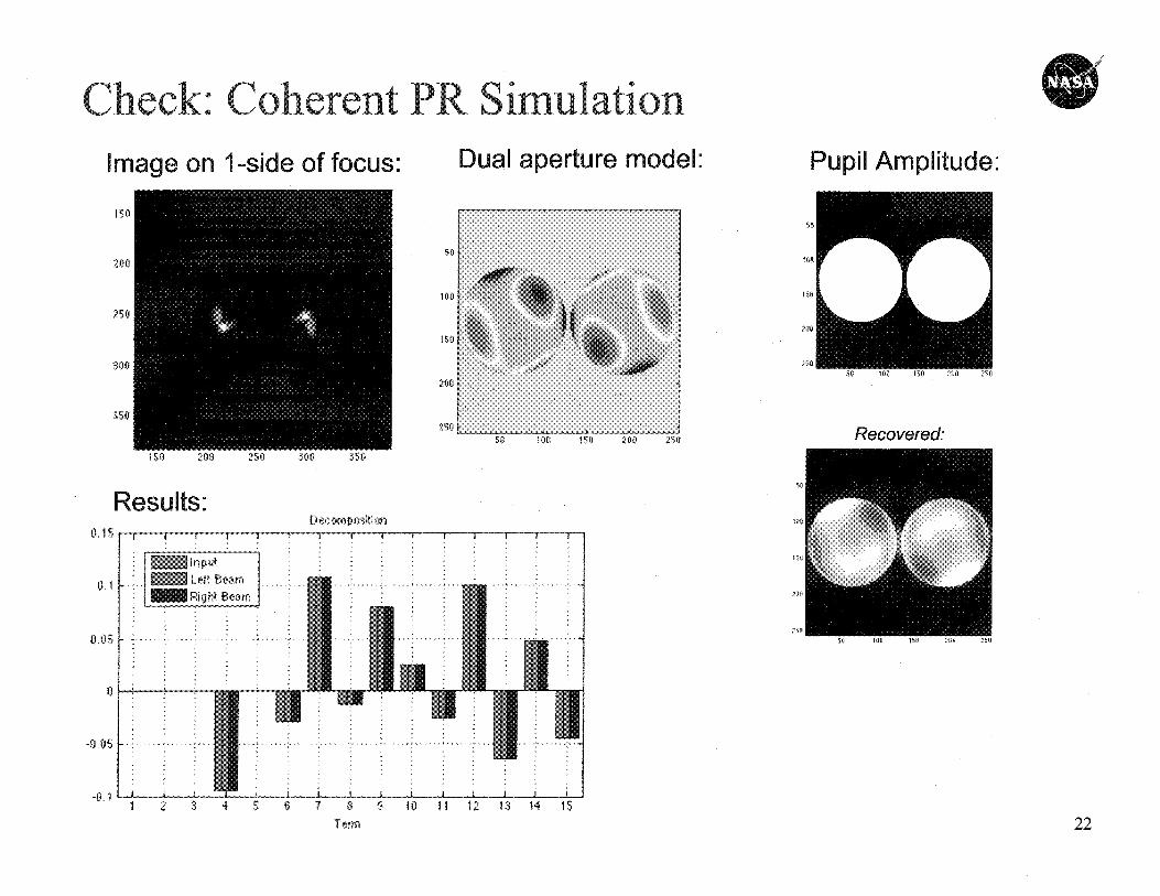
PR SimulationDual aperture model:
b 4 0
so
100
150
200
250
_n 11 2 3 4 5 6 7 8 9 10 11 12 13 14
T erm 22
80 100 120 140 1£r0 160
T
80
100
920
140
160
180
120
140
160
180
80
100
120
140
160
160
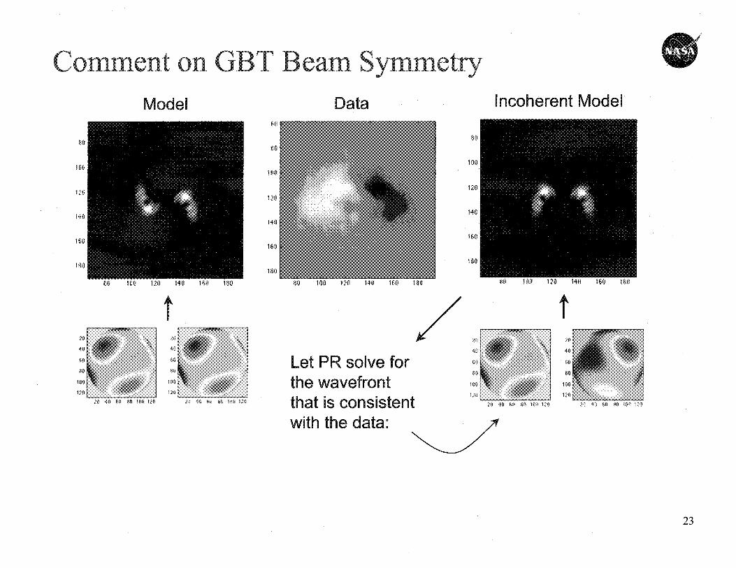
comment on GBT Beale Symmetry 3 ^ l
Model Data Incoherent Model
with the data:
23
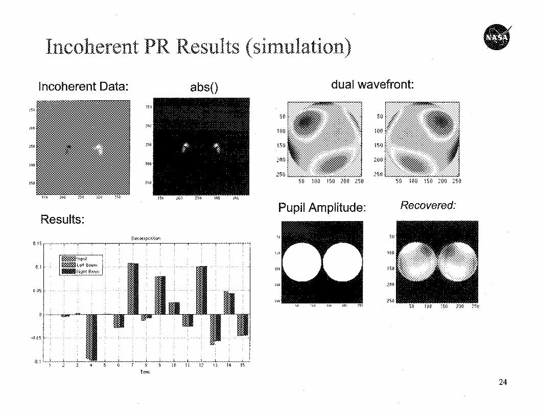
Incoherent Data: abso duaI wavefront:
50 50
00. ..
.
.... ...,so 150
250 25050 100 150 200 250
50
200
50 100 150 200 250
Sty 100 M 20A 2,150
Recovered:
ISO
200
250
ISO 200 250 300 X50
ISO
no
250
300
310
Results:
(1,15
0.1
Decoaipo,*ion 50
wo
M
200
250
Incoherent PR Results (simulation) 0
1 2 3 4 5 6 7 8 9 10 11 12 13 14T emi
24
Recovered.Pup il litResu lts:NCwPOAM
inpcat
Left, 6 ams ...plgltt seam
[d, 1
0.1
-1.1.QS
4 1
-0,1 c
-0
20 40 60 RO 100 20 40 60 80 10 0
40
60
80
100
3-SO
'100
2$0
3013
3613
20 40 60 00 100
50
100
150
200
20
Fo
40
60
80
100
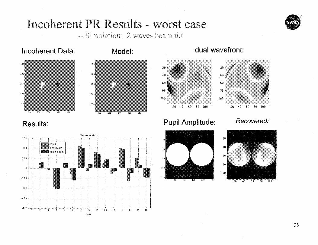
Incoherent PR Results - worst case-- S _ ,^ 2 waves beaiii til t
Incoherent Model: dual r :
s
Tea
25
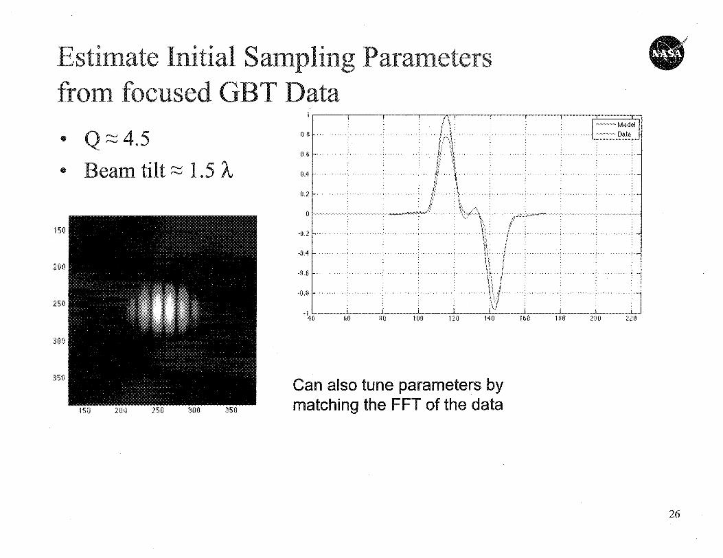
1 Ott 60 80 100 120 440 160 180 200 22
a
Can also tune parameters bymatching the FIFT of the data450 200 250 300 350
301)
26
020
40
60
80
100
20
40
60
80
100
so100
150
200
250
300
350
400
450
100 20 40 60 80 100
Recovered:20 40 60 80 100
Pupil Amplitude:
so
too
150
200
2"
20
40
60
80
100
110 1-1 TO
U
0 15
U.1
41.
, ....
V*
D ec, om p offi on
Lett Ap ertureRight Aperture
............
. . . . . . . . . . 7 . . . . . . . . . . . . . . . .
20 40 60 80 100
1 2 »- 4 5 6 7 8 9 10 11 12 13 14 17 em)
27
so
100
150
200
250
300
3S3
400
450
500
^{ C0^i 0
0
100
4
60
100
20 40 60 80 100
20
40
60
80
too
50
100
154
200
250
imLm
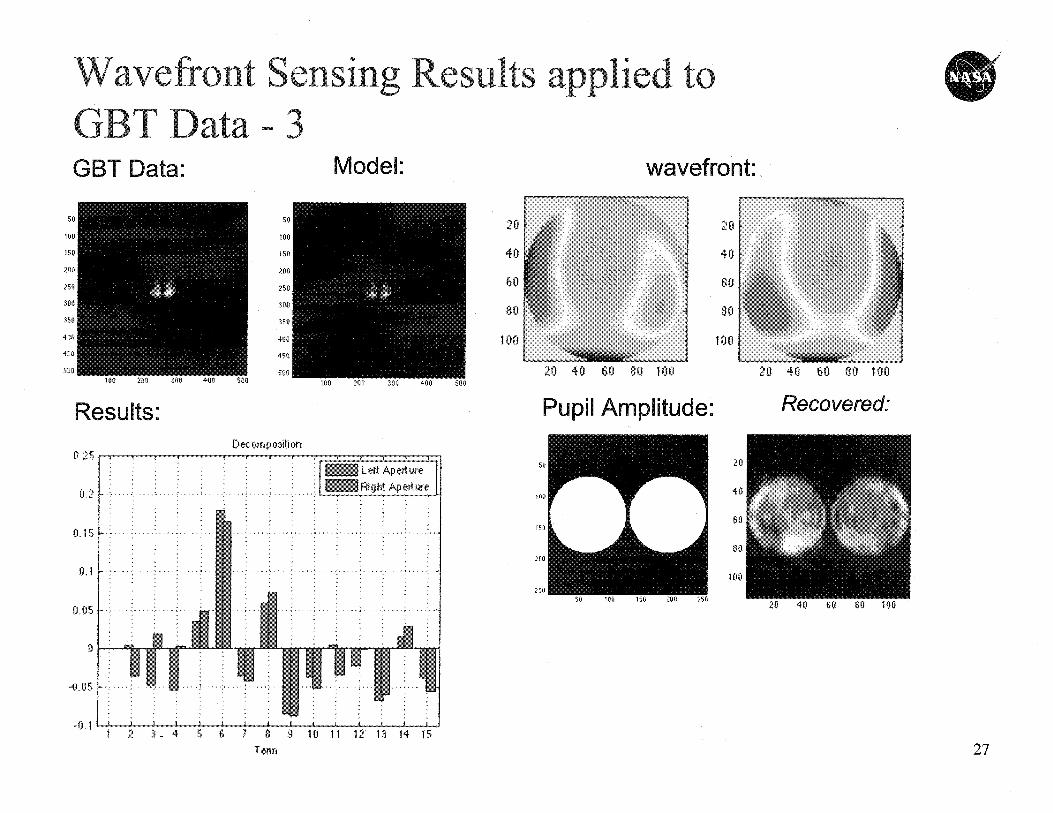
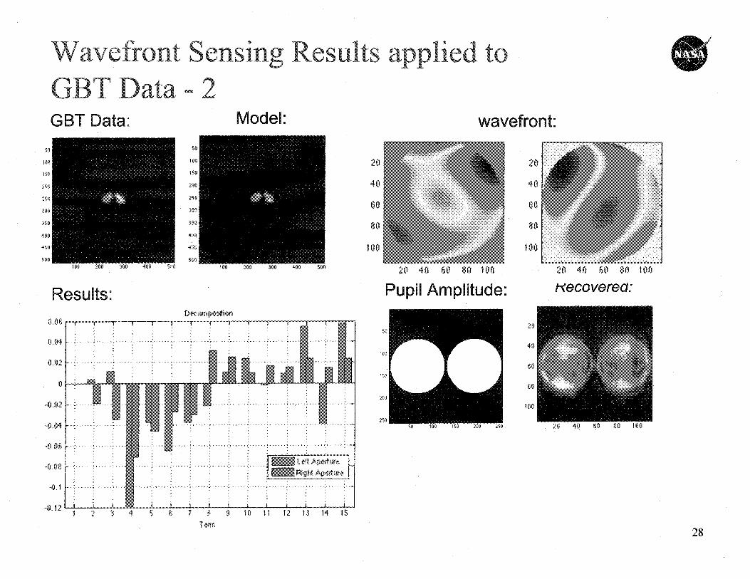
Wavefront Sensing Results applied to a w a
GBT Data - 2Data:GBT
Model: wavefront:50
104
750
200
250
300
3111
400
450
500
Resu lts:
0.06
OM
8,02
V
—0,02
-0,84
-0,06
°0x38
-0A
rib 12
40 60 80 100
Pup il lit0 40 60 80 100
Hecovere :1apobon
1 2 8 4 5 6 7 8 9 10 11 12 13 14 1^
T28

Summary 0
29