Embed Size (px)
Citation preview
I . IBR~Ry R O Y A L ' n " ~ ..... ::~ . . . . . .
MINISTRY OF AVIATION
R . & M . N o . 3 1 7 3 20,870
A.R.C. Technica l Repor t
AERONAUTICAL RESEARCH COUNCIL
REPORTS AND MEMORANDA
Wave Theory of the Mach-Zehnder Interferometer
B y H . K . Z I E N K I E W I C Z
OF THE DEPARTMENT OF THE MECHANICS OF FLUIDS, UN'iVERSITY OF MANCHESTER
LONDON: HER MAJESTY'S STATIONERY OFFICE
196i
NINE SHILLINGS NET
of the Wave Theory
Mach-Zehnder Interferometer
B y H . K . Z I E N K I E W I C Z
OF THE DEPARTMENT OF THE MECHANICS OF FLUIDS, UNIVERSITY OF MANCHESTER
Reports and Memoranda No. 3±73
24th March, z959
Summary. A theory of the Mach-Zehnder interferometer is developed using the approach of investigating the history of a wave front produced by an element of an extended light source. Account is taken of the effects of imperfections of the optical components including all the first-order aberrations of the collimating and collecting lenses or mirrors and of the camera lens. The theory can also be applied to other two-beam inter- ferometers.
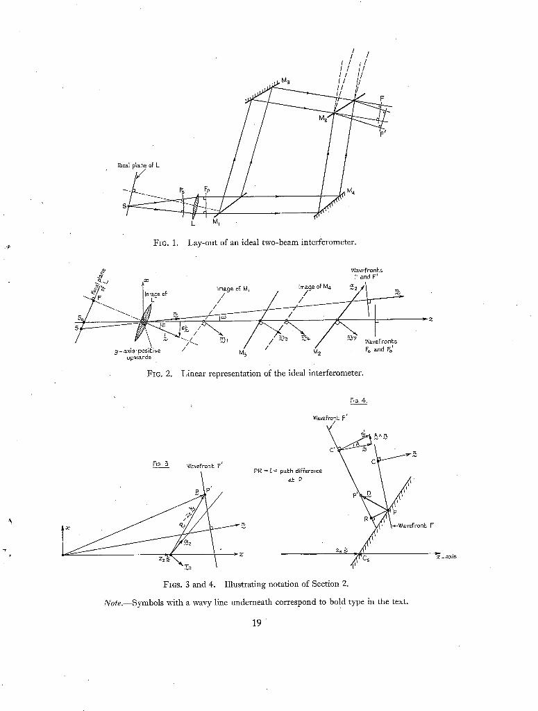
1. Introduction. The Mach-Zehnder interferometer is one of a large class of instruments in which two-beam interference is produced by division of amplitude. Its principle of operation is simple and can be stated very briefly, if the components of the instrument are assumed to be optically perfect. Referring to Fig. 1, S, a point source of monochromatic light in the focal plane of a perfect collimating lens L produces a parallel beam of light which meets a semi-reflecting mirror M 1. This mirror divides the amplitude of the incident light equally between one transmitted and one reflected beam, which are in turn reflected by the fully reflecting mirrors M~and Ms, respectively, andreunited by the second semi-reflecting mirror M s. Since under the idealised conditions assumed the two semi-reflecting mirrors have zero thickness, observable interference would take place beyond M s wherever the two beams overlap*. The fringe pattern would depend only on the relative incli- nation of the two beams; any desired fringe spacing and direction could be obtained by rotating any one of the mirrors about two mutually perpendicular axes in its own plane. Therefore, the theory of the ideal instrument (with a point source of monochromatic light) consists merely of the relation
between the displacements of one of the mirrors and the corresponding fringe spacing and direction. Complications arise when one attempts to take into account departures of a real instrument from_
the ideal model. It is convenient to classify these departures under the following headings:
(a) Light source
(i) Finite band width
(ii) Finite size
* We shall not be concerned, in this paper, with the other pair of beams (shown dotted in Fig. 1) also,. produced by M 2. In this pair, one beam has been reflected once and the other three times; in consequence there is a difference of phase and polarisation between them.
(b) Mirrors (and other glass plates such as wind tunnel windows)
(i) Finite thickness of semi-reflecting mirrors
(ii) Differences of thickness and refractive index between the two semi-reflecting mirrors
(iii) Non-uniform thickness ('wedge shaped' plates)
(iv) Surface irregularities
(c) Aberrations of lenses
(i) Collimating lens (or mirror)
(ii) Collecting lens (or mirror) and camera lens.
The effects of imperfections of mirrors and lenses are linked with those of the light source in the sense that their importance depends on their effects being different for different points (and wavelengths) of the light source. With a point source of monochromatic light, the only effect of mirror and lens imperfections would be a distortion of the fringe pattern. On the other hand, the spectral characteristics and the band width of the source would have very important effects even in the absence of mirror and lens imperfections. For, every element of the source produces a fringe pattern of its own; these patterns overlap and their combined effect depends on the spectrum and
the dimensions of the source, as well as on the arrangement of the mirrors. This has the following most important consequences: first, observable interference will be produced only provided the difference in the optical path length along the two routes between the source and a point on the
screen is not too great, and second, the fringes are localised, i.e., there is an optimum position for observing interference where the contrast of the fringes is highest; to this corresponds an optimum
adjustment of the mirrors which minimizes the effects of the size and the spectrum of the source. The fact that the fringe contrast is governed by the characteristics of the source, the adjustment
of the mirrors and the quality of the optical components stresses the importance of an adequate
and yet reasonably simple theory which takes into account all the essential features of the instrument. The need for such a theory arises both in the design of a new instrument and in the efficient operation of an existing one. In the past, many extravagant notions as to the cost of construction and complexity of adjustment of a Mach-Zehnder interferometer have been widely entertained, largely because of the lack of detailed understanding of the optics of the instrument.
The early theoretical work on the subject, reviewed by Tanner (1956), was unnecessarily restricted to various special cases and many of the results were wrong. The first attempt to give a comprehensive theory was made by Winkler (1947), who considered the aspects listed above under the headings
'(a) and (b). In common with his predecessors, Winkler used laborious ray tracing methods leading to complicated geometrical arguments, some of which the present writer must confess to having failed to follow. The aspects of the theory considered by Winkler and the earlier writers were put on a sound basis by Tanner who, in his 1956 paper, rederived the results obtained previously, correcting those that were in error (in particular, Winkler's conclusions on the effects of the finite" and non- uniform thickness of the semi-reflecting mirrors). Instead of using the conventional ray tracing methods, Tanner expressed the optical path difference between the two beams, at a point on the screen, in terms of the separation of the two images of the point as seen by an observer situated between the collimating lens and the first mirror. This ingenious device leads to a valuable simplifica- tion of the theory; it has, however, obvious didactic drawbacks.
2
The purpose of the present paper is tO put forward an alternative theory based on the physically
direct approach of investigating the history of a wave-front produced by a point of the (extended) light source. The use of elementary vector notation considerably simplifies the analysis and helps to clarify the physical significance of the equations derived. In Section 2 is given the theory of the
ideal interferometer with an extended light source, whilst Section 3 deals with the effects of im- perfections of mirrors and windows. Section 4 is devoted to what the writer believes to be the first complete account of the effects of first-order aberrations of the collimating, collecting and camera lenses. Tanner (1956) considered only the effects of the spherical and of the longitudinal chromatic aberrations of the collimating lens~ In interferometers with a large field of view (greater than, say, 10 cm square), it may be necessary to use spherical mirrors rather than lenses (as good lenses of such dimensions are very costly) and the effects of oblique monochromatic aberrations (coma, astigmatism,
curvature and distortion) may become important.
2. Ideal Interferometer with Extended Light Source. Any point of an extended light source may be regarded as the origin of spherical wave-fronts% If the point is situated in the focal plane of a perfect collimating lens (or mirror) L (Fig. 1), the lens transforms the spherical front F, into a plane front F~. The plane front is divided by the first semi-reflecting mirror into two coherent wave
fronts; of these one istransmitted by M1, reflected by M 4 and M~ and emerges as F ' in Fig. 1, the
other front is reflected by M 1 and M3, transmitted by M~ and emerges as F. Displacements between
the corresponding points of F and F' determine the interference pattern on the screen, as will be
shown below. No observable interference can take place between fronts originating from different
point s of the source. Suppose now that the mirrors are so adjusted that F and F' coincide. Then, an observer looking
into M~ would not be conscious of the particular arrangement of the mirrors. Beyond M~ he would
see M 3 together with the images of the mirrors M~ and M 1 and the image of the lens L (Fig. 2); the coincident wave-fronts would appear to have travelled from O, the centre of the collimating lens, with their centres moving along the straight line joining O to S, the point in the source from which the wave-fronts originated. This 'linear' representation of the interferometer is optically completely
equivalent to the actual arrangement. Consider now a point S o of the source which may be regarded as the 'centre' of the source (it need
not be its geometric centre, but merely a convenient reference point). Then, F0 is a wave-front originating from S o and we take the path of propagation of its centre (i.e., its central ray) as the optical axis of the interferometer and as the z axis of a cartesian co-ordinate system, origin at O, the y axis perpendicular to the plane of the centres of the mirrors~, positive upwards, with the x axis completing the right-handed system; the centres of the mirrors are the points of intersection of the
central ray of F 0 with the mirror planes. Suppose M~ is rotated through a small angle c ~ about an axis in the plane of M 2 passing thro_ugh
its centre. Then, from the laws of reflection it follows that the wave-front F ' reflected by M 2 will be rotated about the same axis through twice the angle; this may be represented by the vector
* The term 'wave' is used here in the sense of a train of surfaces of constant phase which are orthogonal to and propagate along the rays of geometrical optics. This view takes no account of diffraction which is of no significance in our problem (cf. Hopkins, 1950).
It is not necessary for the centres of the mirrors to be co-planar, but it is usually convenient to arrange them so and such arrangement will be assumed throughout the paper.
(78998) A*
a2 ( = 2c%2), Fig. 2. Similarly, a small translation r,,~ in the direction of the mirror unit normal m~ will result in the wave-front translation ,~ = 2%, 2 ( = 2%,2 m~).
Consider a point P' on F', position vector p (Fig. 3). The displacement of P' due to the rotation ¢z2 and translation -c 2 is, to first order in a and %
d 2 = 0 t 2 A ( p - - z2k ) + "c 2
where k is the unit vector in the z direction. Since all the displacements are assumed to be small,
and their squares and higher-order powers are neglected, they are additive. Further, since we are
only concerned with tile relative displacements of the wave-fronts, the displacement of one of the
fronts is equivalent to a displacement of tile other front of equal magnitude but opposite direction.
Thus, for convenience, we may regard F as the 'undisturbed' front and F ' as being affected by
adjustments of all the mirrors (with the signs of a,~1, a~3, %a and -¢~a reversed).-The combined effect of all the mirrors is then a displacement of F ' given by
D =
where k
T =
If n is the unit normal at C,
n I
Then, referring to Fig. 4, if P difference 1 at P is*":
l =
or, by equation (2.2), l =
A a p + T - Xz ia iAk; i = 1, 2, 3, 4 , (2.1) i
Xa, = 2 X ( - 1) ~ ~,~,,
27.~ = 2 27( - 1)i % ~ .
the centre of F, n' , the corresponding miit normal of F ' is
n + AAn. (2.2)
is a point (on the screen S) whose position vector is p~ the pa th
PR
D . n'
n . n + O(A2p, A T ) . (2.3)
Now, D can be shown to be also the displacement between the two images of P in M3, M1 and
in M2, M4, respectively, due to the image rotation A and translation T. Interpreted this way our expression for l is precisely equivalent to Tanner's.
To investigate the dependance of I on source size it is convenient to write n as
n = k cos co + s sin co , (2.4)
where co is the angle between n and the z axis and s is the unit vector in the direction of projection
onto a z = const plane of SoS , the line joining the source point S to the centre of the source (see Fig. 2). Further, if Cs is tile point of intersection of the screen with tile z axis, or the 'centre' of the screen, position vector z~k, equation (2.1) may be written
D = A A r + T + T s , (2.5)
where r = p - z,k, is the position vector of the point P relative to C,, AAr is the rotational displacement of the point P on F due to the rotation A with the axis of rotation passing through the centre of the screen C8, and T~ = 27 (z 8 - zi) ~/xk, is the translation of Cs due to the fact that, in general, tile effective total rotation A is not about an axis passing through C, (Note that T~ has no z component).
* Positive value of I implies that F lags behind FT, i.e., l = path length in beam LM1MaM 2 - path length in beam LM1M4M 2.
With these changes of notation, equation (2.3) becomes
l = (AAr + T + T , ) . (k cos ~o + s sin oJ). (2.6)
T o make 1 independent of the source size to first order in ~o ( 'opt imum adjustment') , we must make
D . s = 0, i.e., there must be no lateral displacement of the wave fronts. This requires:
(1) T . s = 0, i.e., translation in the z direction only.
(2) T~ = 0, i.e., mirror rotations must be such that the effective total rotation is about
the centre of the screen; this determines the mirror rotations necessary to
'focus' the fringes onto the screen.
(3) s . AAr = 0; for this triple scalar p r o d u c t t o vanish we can either:
(i) make s, A, and r co-planar, i.e., the screen must be the z = z, plane and
A must have no z component, or
(ii) A~ = 0, s parallel to A, i.e., the source must be a line (or narrow slit)
parallel to A.
With a non-parallelogram interferometer it is always possible to make A~ = 0, independently of
the other components of A. In a parallelogram interferometer all m i are equal, which results in A~
being proportional to A~. Then, for a given source size, an A~ rotation inevitably involves some loss
of fringe contrast. The effect of Az may be minimised by inclining the screen so that it contains A
(then s . AAr = 0 where r is parallel to A), but this is seldom practicable.
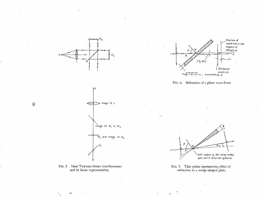
T h e theory of this Section can be applied to other two-beam interferometers. For instance,
Fig. 5 shows the Twyman-Green modification of the Michelson interferometer and its linear
representation. Here, the fringes are always localised in the plane coincident with the images of the
mir rors 2 a n d 3; also, A can have no z component, so that fringe contrast is, to first order,
independent of the source size.
3. Effects of Finite Thickness and Imperfections of Gla:ss Plates. 3.1. Flat Plates of Uniform Thickness an d Refractive Index. Consider a plane wave-front F which is t ransmitted by a flat
glass plate of uniform thickness t and refractive index /x (Fig. 6). F is incident at an angle/3 on
the plate whose unit normal is m, so that m . n = cos fi, where as before n is the unit normal
to the wave-front. Refraction in the plate produces two effects (ignoring changes of phase and
polarisation).
(i) Increase of optical path of amount tF(u, t~), where F(u, /x) = ~/{(t~ ~ - 1) + u ~} - u; u = cos/3 = m . n. This corresponds to a backward displacement of F along its normal
equal to - tFn.
(ii) Transverse shift of F of amount - tF~ sin/3 in the direction normal to n and in the plane
of n and m, i.e.; in the direction of (m - un). This corresponds to a displacement
- t (m - un)F~, where F~, = OF/~u.
Let the pr imed quantities refer to the corresponding plate through which the wave-front F ' is
transmitted. Then, the change of the optical path difference is
81 = tF(u, t~) - t'F'(u', t~'). (3.1.1)
(78998) A* 2
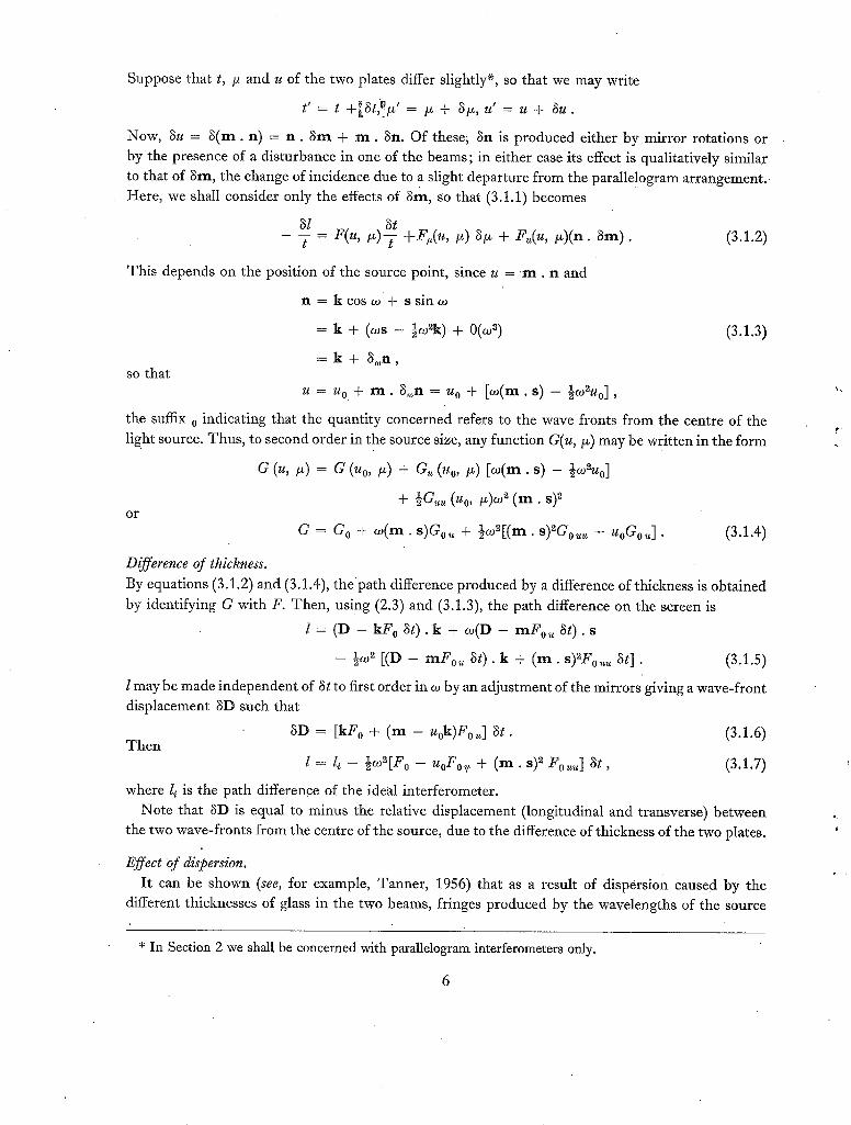
Suppose that t, /z and u of the two plates differ slightly*, so that we may write
t' = t + ~ t , ~ ' = ~ + ~ , u' = u + ~ u .
Now, 3u = 3 ( m . n) = n . 3m + m . 3n. Of these~ 3n is produced either by mirror rotations or
by the presence of a disturbance in one of the beams; in either case its effect is qualitatively similar
to that of 3m, the change of incidence due to a slight departure f rom the parallelogram arrangement.
Here, we shall consider only the effects of 3m, so that (3.1.1) becomes
_ 3__lt = F(u, 1~)3--t t +F~(u, i~) 31z + F~(u, /z)(n . 3m) . (3.1.2)
This depends on the position of the source point, since u = ' m . n and
n = k c o s w + ssin~o
= k + (~os - ½oJZk) + 0(w ~) (3.1.3)
= k + 3~n , so that
u = Uo + m . 3,on = u o + [~o(m. s) - ½cO2Uo] ,
the suffix o indicating that the quantity concerned refers to the wave fronts from the centre of the
light source. Thus , to second order in the source size, any function G(u, tz) may be written in the form
G (u, I-0 = a (Uo, I z) + Gu (Uo, t ~) [eo(m. s) - ½~O~Uo]
1 (%, ( m . + ~ G ~ t~)~o ~ s) 2 o r
G = G O + ~o(m. s)Go~ , + ½~o~[(rn. s)~Go~ - uoGo, ] . (3.1.4)
Difference of thickness. By equations (3.1.2) and (3.1.4),
by identifying G with F. Then,
l =
l may be made independent of 3t
displacement 3D such that
3D = [kF 0 + ( m - u0k)F0~ ] St . T h e n
l = l~-- ½co~[Fo-- u o F o ~ " + ( r e . s ) 2Fouu] at,
where li is the path difference of the ideal interferometer.
t h e p a t h difference produced by a difference of thickness is obtained
using (2.3) and (3.1.3), the path difference on the screen is
( D - k F 0 3 t ) . k + ~ o ( D - m F 0 ~ 3 0 . s
- ½oJ 2 [(D - m F o~ 3t) . k + ( m . s )2F0~ St] . (3.1.5)
to first order in co by an adjustment of the mirrors giving a wave-front
(3.1.6)
(3.1.7)
Note that SD is equal to minus the relative displacement (longitudinal and transverse) between
the two wave-fronts f rom the centre of the source, due to tile difference of thickness of the two plates.
Effect of dispersion. I t can be shown (see, for example, Tanner , 1956) that as a result of dispersion caused by the
different thicknesses of glass in the two beams, fringes produced by the wavelengths of the source
* In Section 2 we shall be concerned with parallelogram interferometers only.
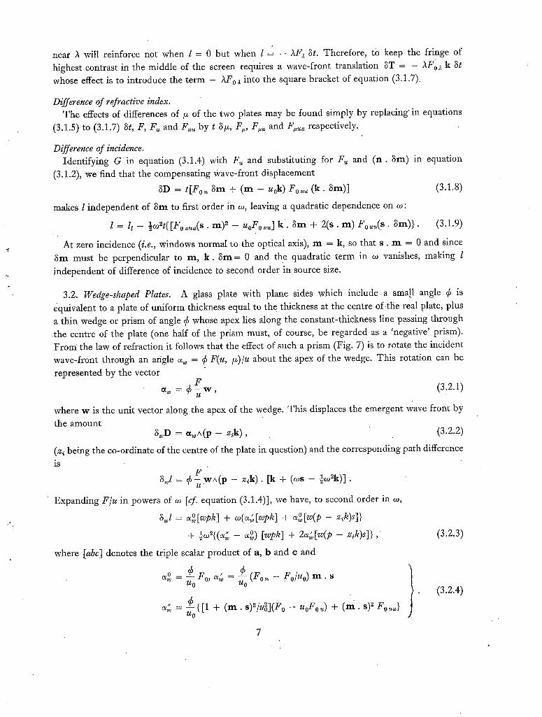
near )t will reinforce not when l = 0 but when 1 = - )tFa St. Therefore, tO keep the fringe of
highest contrast in the middle of the screen requires a wave-front translation ST = - AF 0 a k St
whose effect is to introduce the term - AF 0 a into the square bracket of equation (3.1.7)~
Difference of refractive index. The effects of differences, of/~ of the two plates may be found simply by replacing' in equations
(3.1.5) to (3.1.7) St, F, F~ and Fuu by t S/z, F~, Fro, and F~u~ respectively.
Difference of incidence. Identifying G in equation (3.1.4) with F~, and substituting for F , and (n . Sm) in equation
(3.1.2), we find that the compensating Wave-front displacement
SD = t[Fo~ ~m + (m - u0k ) Fo~, (k . Sm)] (3.1.8)
makes I independent of 8rn to first order in 02, leaving a quadratic dependence on 02:
l = li - ½02~t([Fo~u~(s • m) 2 - u0F0~] k . 8m + 2(s. m) F0~(S . 8m)}. (3.1.9)
At zero incidence (i.e., windows normal to the optical axis), m = k, so that s . m = 0 and since ~m must be perpendicular to m, k . 8 m = 0 and the quadratic term in o~ vanishes, making l
independent of difference of incidence to second order in source size.
3.2. Wedge-shaped Plates. A glass plate with plane sides which include a small angle ~ is
equivalent to a plate of uniform thickness equal to the thickness at the centre of the real plate, plus
a thin wedge or prism of angle ~6 whose apex lies along the constant-thickness line passing through the centre of the plate (one half of the prism must, of course, be regarded as a 'negative' prism). From the law of refraction it follows that the effect of such a prism (Fig. 7) is to rotate the incident wave-front through an angle ~, = ~6 F(u, i~)/u about the apex of the wedge. This rotation can be
represented by the vector
~ = ~ : ~ w , (3.2.1)
where w is the unit vector along the apex of the wedge. This displaces the emergent wave front by
the amount 3~D = ~ A ( p - z~k), (3.2.2)
(zi being the co-ordinate of the centre of the plate in question) and the corresponding path difference
is
s~l = 6 ~ w A ( p - ~,k). [k + (02s - ~02~k)J.
Expanding F'/u in powers of 02 [cf. equation (3.1.4)], we have, to second order in 02,
s j = ~o[wpk] + 02(~[wpk] + ~o[~(p _ z,k)s]}
1 2 " / u p + ~ , ~ _ ~o) [~pk ] + 2~w[~(p - z~k)s]} ,
where [abc] denotes the triple scalar product of a, b and e and
a° = ~ Fo, a~o = ~ (Fo~ - Fo/uo) m . s
7~.~ {[1 + ( m . s)2/u~](Fo - uoFo~,) + ( m . s)~ Fo~,} ~o
(3.2.3)
. (3.2.4)
7
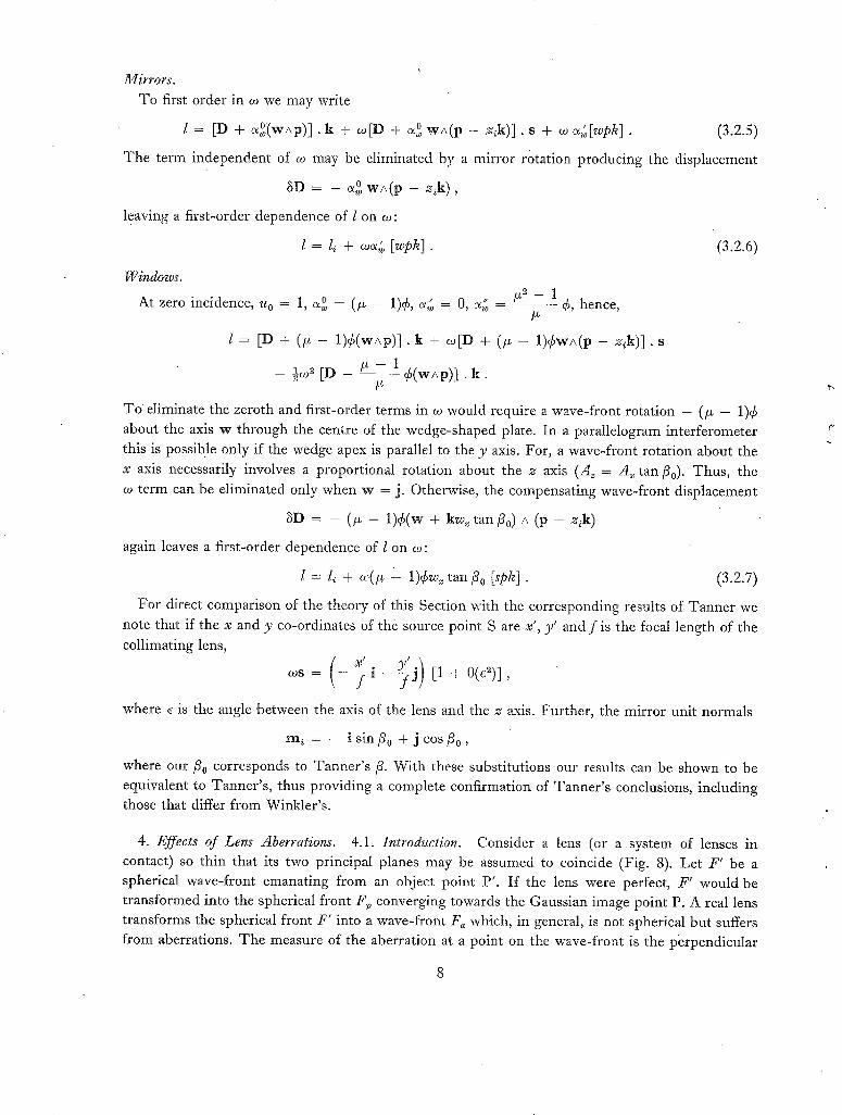
Mirrors. To first order in co we may write
• 0 w A ( p - z , k ) ] , s + co ~ [ w p h ] (3.2.5) l = [D + a ° ( w / \ p ) ] k + co[D + c~,~ ' .
T h e te rm independent of co may be eliminated by a mirror rotation producing the displacement
3D = - ~o wA(p - z~k),
leaving a first-order dependence of l on co:
l = l~ + co~; [wph]. (3.2.6)
Windows.
At zero incidence, u 0 = 1, s ° = (/z - 1)¢, ~ = 0, c~ - /~ - 1 ¢, hence, /z
l = [D + (~ - 1 ) ¢ ( w a p ) ] . k + co[D + (t* - 1 )¢wa(p - z # ) ] . s
- ~ [D ~ - 1 4 ( w ~ p ) ] . k . /z
TO eliminate the zeroth and first-order te rms in co would require a wave-front rotation - (/~ - 1)¢
about the axis w through the centre of the wedge-shaped plate. In a parallelogram interferometer
this is possible only if the wedge apex is parallel to the y axis. For, a wave-front rotation about the
x axis necessarily involves a proport ional rotation about the z axis (A~ = A~ tan/3o). Thus , the
co te rm can be eliminated only when w = j. Otherwise, the compensat ing wave-front displacement
3D = - (/x - 1)¢(w + kw.. tan/30) A (p - zik)
again leaves a first-order dependence of l on co:
l = l~ + a,(~ - 1)¢w.. tan/30 [sph]. (3.2.7)
For direct comparison of the theory of this Section with the corresponding results of Tanne r we
note that if the x and y co-ordinates of the source point S are x', y ' and f is the focal length of the
collimating lens,
c o s = - 7 i - j [1 + O(e2)],
where ~ is the angle between the axis of the lens and the z axis. Further , the mirror unit normals
m i = - - i sin/30 + J cos/30,
where our/30 corresponds to Tanner ' s /3. With these substitutions our results can be shown to be
equivalent to Tanner ' s , thus providing a complete confirmation of Tanner ' s conclusions, including
those that differ f rom Winkler 's .
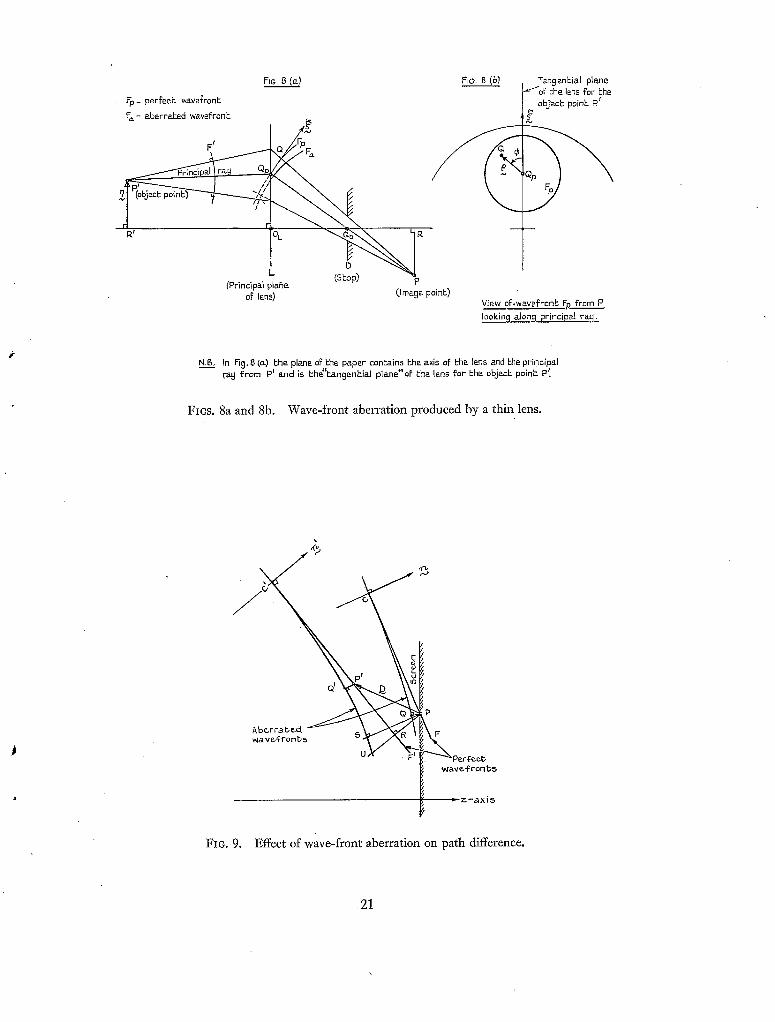
4. Effects of Lens Aberrations. 4.1. Introduction. Consider a lens (or a system of lenses in
contact) so thin that its two principal planes may be assumed to coincide (Fig. 8). Le t F ' be a
spherical wave-front emanating f rom an object point P' . I f the lens were perfect, F' would be
t ransformed into the spherical front F v converging towards the Gaussian image point P. A real lens
t ransforms the spherical front F' into a wave-front F~ which, in general, is not spherical but suffers
f rom aberrations. T h e measure of the aberration at a point on the wave-front is the perpendicular
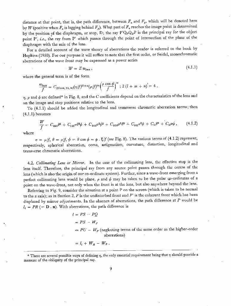
distance at that point, that is, the path difference, between F~ and F~, which will be denoted here by w (positive when F~ is lagging behind F~). What part of F~ reaches the image point is determined
by the position of the diaphragm, or stop, D ; the ray P'QpQDP is the principal ray for the object point P', i.e., the ray from P' which passes through the point of intersection of the plane of the
diaphragm with the axis of the lens. For a detailed account of the wave theory of aberrations the reader is referred to the book by
Hopkins (1950). For our purpose it will suffice to note that the first order, or Seidel, monochromatic
aberrations of the wave front may be expressed as a power series
W = Z w ~ , ~ , (4.1.1)
where the general term is of the form
~ _ C(2~+~,2,~,,o(~/f)2~+,,~(p/f)2'~(~-f~; 2 (l + m + n) '= 4 .
7, P and ¢ are defined* in Fig. 8, and the C coefficients depend on the characteristics of the lens and
on the image and stop positions relative to the lens. To (4.1.1) should be added the longitudinal and transverse chromatic aberration terms; then
(4.1.1) becomes
W - f _ Co,toO~ + C~1~0~¢ + C 2 0 ~ ¢ 2 + C2~oa202 + C30~3¢ + C,~O 2 + Ct~a¢, (4.1.2)
where
respectively, spherical aberration, transverse chromatic aberrations.
a = t~/f, 0 =- p/f, ~b = 0 cos ¢ = 9. ~/ f (see Fig. 8). The various terms of (4.1.2) represent, coma, astigmatism, curvature, distortion, longitudinal and
4.2. Collimating Lens or Mirror. In the case of the collimating lens, the effective stop is the
lens itself. Therefore, the principal ray from any source point passes through the centre of the lens (which is also the origin of our co-ordinate system). Further, since a wave-front emerging from a perfect collimating lens would be plane, p and ¢ may be taken to be the polar qo-ordinates of a point on the wave-front, not only when the front is at the lens, but also anywhere beyond the lens.
Referring to Fig. 9, consider the situation at a point P on the screen (which is taken to be normal to the z axis) ; as in Section 2, F is the undisturbed front and F' is the coherent front which has been displaced by mirror adjustments. In the absence of aberrations, the path difference at P would be
li = P R (= D . n). With aberrations, the path difference is
I = P S - PQ
= P s - w p
-'~ P U - Wp (neglecting terms of the same order as the higher-order
aberrations)
= l~ + w R - w p .
* There are several possible ways of defining ~7, the only essential requirement being that ~7 should provide a measure of the obliquity of the principal ray.
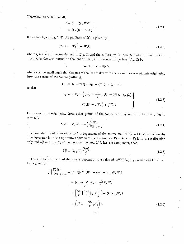
Therefore, since D is small,
l = l ~ + D . V W } .
= D . (n + v w ) (4.2.1)
I t can be shown that V W, the gradient of W, is given by
f V W = Wo-p + W,p~, (4.2.2)
where ~ is the unit vector defined in Fig. 8, and the suffices on W indicate partial differentiation. Now, let the unit normal to the lens surface, at the centre of the lens (Fig. 2) be
, 1 = e t + k + 0 ( e 2 ) ,
where e is the small angle that the axis Of the lens makes with the z axis. For wave-fronts originating from the centre of the source (suffix 0),
so that p = too = r ;~ l '=~ lo = ef t ,~ = ~o = t ,
), Oo, 0"0 = G, 0 0
• (4.2.3)
f V o W oWo r_ + oW, p t t"
For wave-fronts originating from other points of the source we may write to the first order in
V W = V oW + ~ - - - . (4.2.4)
The contribution of aberrations to l, independent of the source size, is 3°l = D . VoW. When the
interferometer is in the optimum adjustment (cf. Section 2), D ( = A Ar + T) is in the z direction only and S°l = O, for VoW has no z component. If A has a z component, then
f (4.2.5)
The effects of the size of the source depend on the valuc of (0VW/O~)~=0, which can be shown to be given by
f \~]~=o(SVW] = ( t . s)[efVoW o - (ez 8 + r . t)VoW~]
ez, V o Wo] + ( r . s) v0w~ - -~-
6.g,s ) + °W'P r °W° s (4.2.6)
10
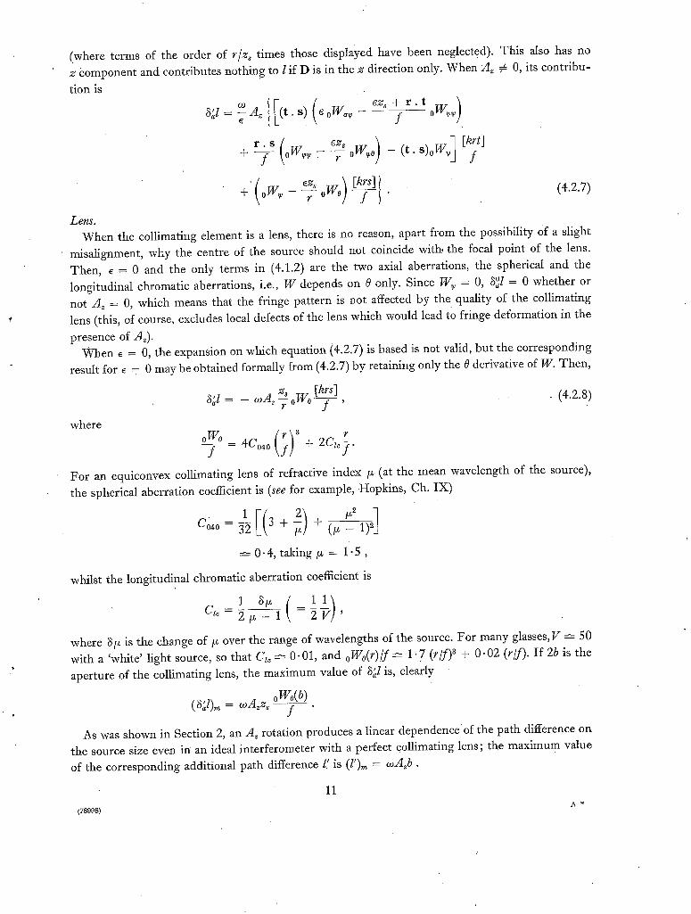
(where terms of the order of r/z= times those displayed have been neglected ). This also has no z component and contributes nothing to l if D is in the z direction only. When S/z # 0, its contribu-
tion is
S~l = toe A~ t . s) e 0W,~ f 0W~
( ) 1 • . s ~=~ oW~o - ( t s ) o W , , + - f - 0w~ ~ • f
' ( _ eZ. o W o ) ~ l (4.2.7) + t °W" 7
Lens. When the collimating element is a lens, there is no reason, apart from the possibility Of a slight
misalignment, why the centre of the source should not coincide with, the focal point of the lens. Then, E = 0 and the only terms in (4.1.2) are the two axial aberrations, the spherical and the
longitudinal chromatic aberrations, i.e., W depends on 0 only. Since W~ = 0, S°l = 0 whether or not A~ = 0, which means that the fringe pattern is not affected by the quality of the collimating
lens (this, of course, excludes local defects of the lens which would lead to fringe deformation in the
presence of A,). When ~ = 0, the expansion on which equation i4.2.7) is based is not valid, but the corresponding
result for E = 0 may be obtained formally from (4.2.7) by retaining only the 0 derivative of W. Then,
z= [krs] . (4.2.8) S~l = - o~A, r °W° f '
where
f - 4Co40 +
For an equiconvex collimating lens of refractive index ff (at the mean wavelength of the source),
the spherical aberration coefficient is (see for example, Hopkins, Ch. IX)
= _1 pfl [(3+ 0.4, taking/~ = 1 .5 ,
whilst the longitudinal chromatic aberration coefficient is
11) C z , - ~ f f ~ l = 2 V '
where ~/~ is the change of/~ over the range of wavelengths of the source. For many glasses,V ~ 50
with a 'white' light source, so that C~o ~- 0.01, and oWo(r) / f ~ 1 .7 (r / f ) ~ + 0.02 (r/f) . If 2b is the
aperture of the collimating lens, the maximum value of S~l is, clearly
oWo(b) (SJ)m = ~oA~z= f
As was shown in Section 2, an A= rotation produces a linear dependence of the path difference on the source size even in an ideal interferometer with a perfect collimating lens; the maximum value
of the corresponding additional path difference l' is (l'),~ = ~oA=b.
11 A*
(78998}
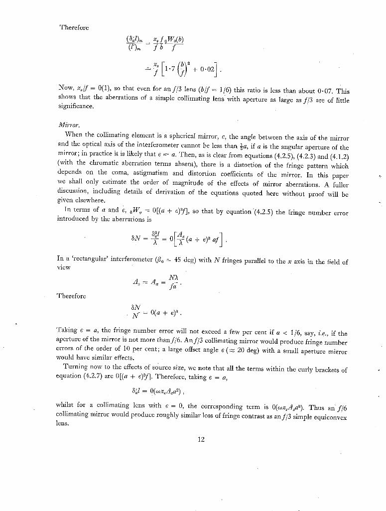
Therefore
( ~ J ) . , = _ ~./oWo(b) (l')~ f b f
( ; ; + o.o j . Now, z , / f = 0(1), so that even for an f /3 lens (b/f = 1/6) this ratio is less than about 0.07. This shows that the aberrations of a simple collimating lens with aperture as large as f/3 are of little significance.
Mirror.
When the collimating element is a spherical mirror, e, the angle between the axis of the mirror and the optical axis of the interferometer cannot be less than ½a, if a is the angular aperture of the mirror; in practice it is likely that e ~ a. Then, as is clear from equations (4.2.5), (4.2.3) and (4.1.2)
(with the chromatic aberration terms absent), there is a distortion of the fringe pattern which
depends on the coma, astigmatism and distortion coefficients of the mirror. In this paper
we shall only estimate the order of magnitude of the effects of mirror aberrations. A fuller discussion, including details of derivation of the equations quoted here wi thout proof will be given elsewhere.
In terms of a and e, oWe = 0[(a + e)af], so that by equation'(4.2.5) the fringe number error introduced by the aberrations is
In a 'rectangular' interferometer (/9 o = 45 deg) with N fringes parallel to the x axis in the field of view
Therefore
3N ~ - = 0 ( a + e) 3 .
Taking e = a, the fringe number error will not exceed a few per cent if a < 1/6, say, i.e., if the aperture of the mirror is not more than f /6. An f /3 collimating mirror would produce fringe number errors of the order of 10 per cent; a large offset angle e (m 20 deg) with a small aperture mirror would have similar effects.
Turning now to the effects of source size, we note that all the terms within the curly brackets of equation (4.2.7) are 0[(a + e)af]. Therefore, taking e = a,
8~1 = O(oozsA~a~),
whilst for a collimating lens with e = 0, the corresponding term is O(~ozsA~aa). Thus an" f /6 collimating mirror would produce roughly similar loss of fringe contrast as an f /3 simple equiconvex lens.
12
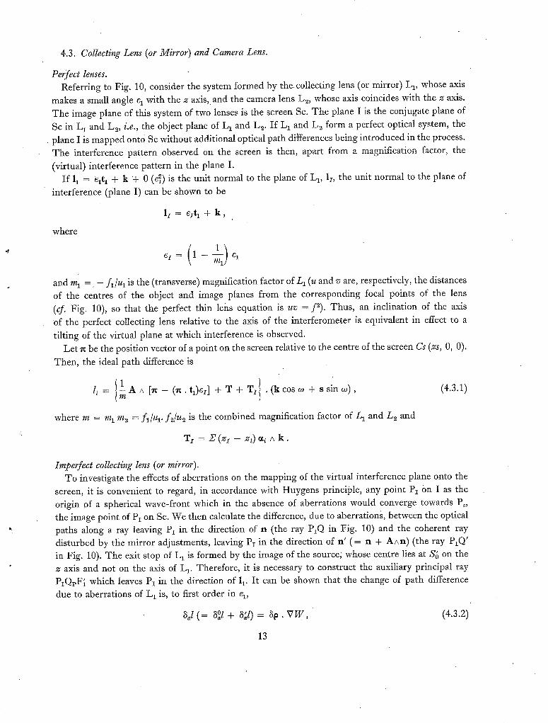
4.3. Collecting Lens (or Mirror) and Camera Lens.
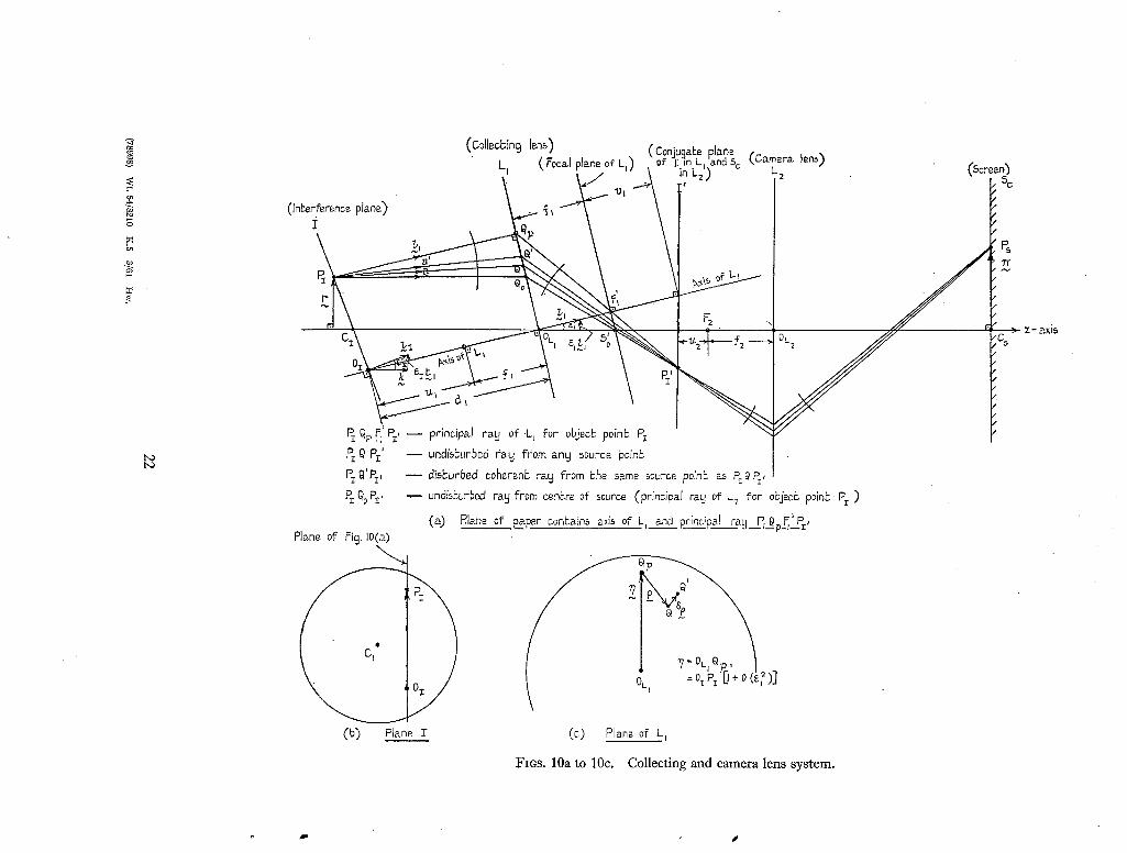
Per~fect lenses. Referring to Fig. 10, consider the system formed by the. collecting lens (or mirror) L~, whose axis
makes a small angle q with the z axis,• and the camera lens L2, whose axis coincides with the z axis.
The image plane of this system of two lenses is the screen Sc. The plane I is the conjugate plane of
Sc in L 1 and L~, i.e., the object plane of L 1 and L~. If L 1 and Lo. form a perfect optical system, the
• plane I is mapped onto Sc without additional optical path differences being introduced in the process.
The interference pattern observed on the screen is then, apart from a magnification factor, the
(virtual) interference pattern in the plane I. I f 11 = e l t a + k + 0 (e~) is the unit normal to the plane of L 1, lz, the unit normal to the plane of
interference (plane I) can be shown to be
l i = e i t l + k ,
where
and m 1 = - ft/u~ is the (transverse) magnification factor of/-a (u and v are, respectively, the distances
of the cent'res of the object and image planes from the corresponding focal points of the lens
(cf. Fig. 10), so that the perfect thin lens equation is uv = f"). Thus, an inclination of the axis
of the perfect collecting lens relative to the axis of the interferometer is equivalent in effect to a
tilting of the virtual plane at which interference is observed. Let ~ be the position vector of a point on the screen relative to the centre of the screen Cs (zs, O, 0).
Then, the ideal path difference is
l' I li = m A A [re - ( n . tl)ez] + T + T I . (k cos oJ + s sin co), (4.3.1)
where m = m 1 m 2 = fa/zq, fz/u~ is the combined magnification factor of L 1 and L 2 and
T z = Z' ( z i - z~) ,x~/ , k .
Imperfect collecting lens (or mirror). To investigate the effects of aberrations on the mapping of the virtual interference plane onto the
screen, it is convenient to regard, in accordance with Huygens principle, any point P1 On I as the origin of a spherical wave-front which in the absence of aberrations would converge towards Ps, the image point of PI on Sc. We then calculate the difference, due to aberrations, between the optical paths along a ray leaving PI in the direction of n (the ray P~Q in Fig. 10) and the coherent ray
disturbed by the mirror adjustments, leavilig PI in the direction of n ' (= n + AAn) (the ray PIQ' in Fig. 10). The exit stop of L t is formed by the image of the source;' whose centre lies at 86 on the
z axis and not on the axis of L 1. Therefore, it is necessary to construct the auxiliary principal ray P~QrF{ which leaves P1 in the direction of 1 v It can be shown that the change of path difference
due to aberrations of L 1 is, to first order in q,
3~1 ( = 3°l + 3~l)= 31:. VW, (4.3.2)
13
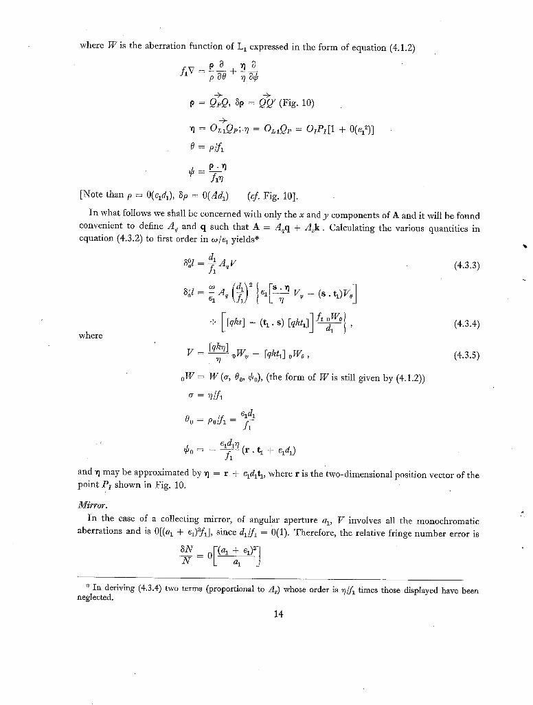
where W is the aberration function of L 1 expressed in the form of equation (4.1.2)
flV p ~ ~ O p~O + - -
p = QpQ, 3 0 = QQ' (Fig. 10)
0 = o/f~
Oz,Q,; ,~ = Oz~Qv = ozPz[1 + 0(e12)]
¢' - f~(7 [Note than p = O(eldl) , ~p = 0(Adl) (@ Fig. 10].
In what follows we shall be concerned with only the x and y components of A and it will be found convenient to define Aq and q such that A = A~q + A~k. Calculating the various quantities in equation (4.3.2) to first order in o~/e 1 yields ~
3°1 = ~ AeV (4.3.3)
where
8J =
g = - -
o W =
O"
l ] cl ~ ] q v~ - (s . tl)Vo
+ [[qks]-(t 1.s) [qktl] ]f1-~1 I ' °W°
[@3] ~ _ [qkh] oWo
W @, 0o, ¢o), (tile form of W is still given by (4.1.2))
(4.3.4)
(4.3.s)
Cldt Oo = Po/A - A
A "
and v I may be approximated by ~1 = r + qdlt~, where r is the two-dimensional position vector of the point Pz shown in Fig. 10.
Mirror. In the case of a collecting mirror, of angular aperture al, V involves all the monochromatic
aberrations and is 0[(a 1 + Cl)afl], since dl/fl = ()(1). Therefore, the relative fringe number error is
3N [ ( a 1 + el)31 - R _ 0 -
al A
* In deriving (4.3.4) two terms (proportional to Az) whose order is ~?/ft times those displayed have been neglected.
14
(Note that for the collimating mirror this was only 0[(a + e)a]. Thus, the aperture of the collecting
mirror should not exceed fl/10 and e I should be kept as small as possible. With q = a 1, the terms in the curly bracket of equation (4.3.4) are O(f~az3), so that as for the collimating mirror 3J = O(oJfxAa~ 2) and this will not have any significant effects on fringe contrast if the aperture of the collecting
mirror is small enough to avoid appreciable fringe distortion.
Lens. When the collecting element is a lens, we take q = 0. Then, p and 3p are both 0(Adl), so that
0 and ~b are both 0(A). Since we have neglected terms 0(A) z throughout the analysis, in equations (4.3.3) and (4.3.4) we need only retain the derivatives of 0W which are of zeroth order in A (i.e., zeroth order in 0 and ~b). As a result, these equations become
d~ [qkr] W, (4.3.6) r o
{dl] ~ I r " s [qhr] oWv,;l (4.3.7) aJ=o A, fj [@s]0w00+ r 7 '
where 0W~ involves only distortion and transverse chromatism,
oWoo involves only curvature and longitudinal chromatism,
0W~ involves only astigmatism,
the two chromatic aberrations being of little importance except, perhaps, with white light fringes.
Assuming that the collecting lens has not been specially designed, the orders of magnitude of its
3°l and 3~1 will be the same as for a spherical mirror of equal aperture, and the same gloss applies.
Imperfect camera lens. The equations expressing the effects of aberrations of the camera lens Lz may be obtained directly
from those for the collecting lens if d 1 is replaced by - d2/ml and f l is replaced by f2, where d 2 = u~ + f2 (see Fig. 10) and m 1 = - f~/ul is the (transverse) magnification factor of L 1.
It is usually necessary and convenient to arrange the lenses so that L~ is near the image of the
light source formed by L 1 i n its focal plan e. This has two advantages:
(i) L 2 need only have a small aperture (f2/40 is not uncommon),
(ii) When the 'undisturbed' image of the centre of the source coincides with the centre of Lz, the principal ray of L 2 (the ray PIQoP'I in Fig. 10) passes through the centre of L~; then, the
distortion and the transverse chromatic aberration of the lens are zero.
15
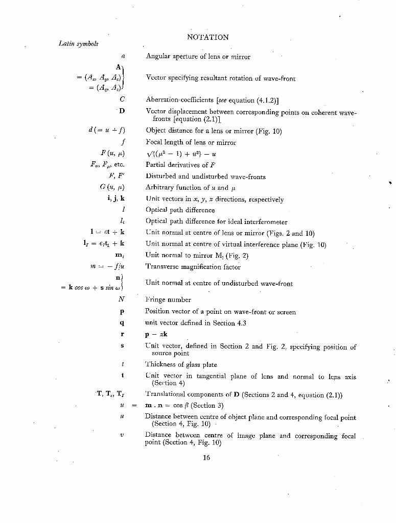
Latin symbols
a
= (A~, A~, A ) = (A~, Az)J
C
D
d ( = . + f )
f F (., ~)
Fu, )V, etc.
F , F '
i , j , k
l
l, l = e t + k
lr = ezt 1 + k
m ~
m = - f / ¢ l
= k c os o~+ ssin:l N
T, T~, Tx
u
N O T A T I O N
Angular aperture of lens or mirror
Vector specifying resultant rotation of wave-front
Aberration. coefficients [see equation (4.1.2)]
Vector displacement between corresponding points on coherent wave- fronts [equation (2.1)].
Object distance for a lens or mirror (Fig. 10)
Focal length of lens or mirror
~/{(~ - 1) + u 2} - u
Partial derivatives of F
Disturbed and undisturbed wave-fronts
Arbitrary function of u and /,
Unit vectors in x, y, z directions, respectively
Optical path difference
Optical path difference for ideal interferometer
Unit normal at centre of lens or mirror (Figs. 2 and 10)
Unit normal at centre of virtual interference piane (Fig. 10)
Unit normal to mirror M i (Fig. 2)
Transverse magnification factor
Unit normal at centre of undisturbed wave-front
Fringe number
Position vector of a point on wave-front or screen
unit vector defined in Section 4.3
p - z k
Unit vector, defined in Section 2 and Fig. 2, specifying position of source point
Thickness of glass plate
Unit vector in tangential plane of lens and normal to leps axis (Section 4)
Translational components of D (Sections 2 and 4, equation (2.1))
m . n = cos fi (Section 3)
Distance between centre of object plane and corresponding focal point (Section 4, Fig. 10)
Distance between centre of image plane and corresponding focal point (Section 4, Fig. 10)
16
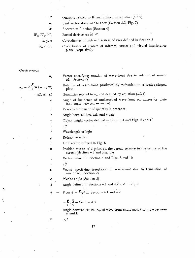
V
W
W
wo, w.,w X, y , 2;
Zi , ~s, Z I
Quantity related to W and defined in equation (4.3.5)
Unit vector along wedge apex (Section 3.2, Fig. 7)
Aberration function (Section 4)
Partial derivatives bf W
Co-ordinates in cartesian system of axes defined in Section 2
Co-ordinates of centres of mirrors, screen and virtual interference plane, respectively
Greek symbols
O~ w = ¢ F ?w(=
0 t ++
B
S
£
0
7~
G
,¢
¢
¢
¢O
Vector specifying rotation of wave-front due to rotation of mirror M 1 (Section 2)
Rotation of wave-front produced by refraction in a wedge-shaped plate
Quantities related to a w and defined by equation (3.2.4)
Angle of incidence of undisturbed wave-front on mirror or plate (i.e., angle between m and n)
Denotes increment of quantity it precedes
Angle between lens axis and z axis
Object height vector defined in Section 4 and Figs. 8 and 10
o/f Wavelength of light
Refractive index
Unit vector defined in Fig. 8
Position vector of a point on the screen relative to the centre of the screen (Section 4.3 and Fig. 10)
Vector defined in Section 4 and Figs. 8 and 10
n/f Vector specifying translation of wave-front due to translation of
mirror M~ (Section 2)
Wedge angle (Section 3)
Angle defined in Sections 4.1 and 4.2 and in Fig. 8
0 cos ¢ = P-f~ in Sections 4.1 and 4.2
0 Y1 in Section 4.3 - f l" ~/ Angle between central ray of wave-front and z axis, i.e., angle between
n and k
oJ/e
17
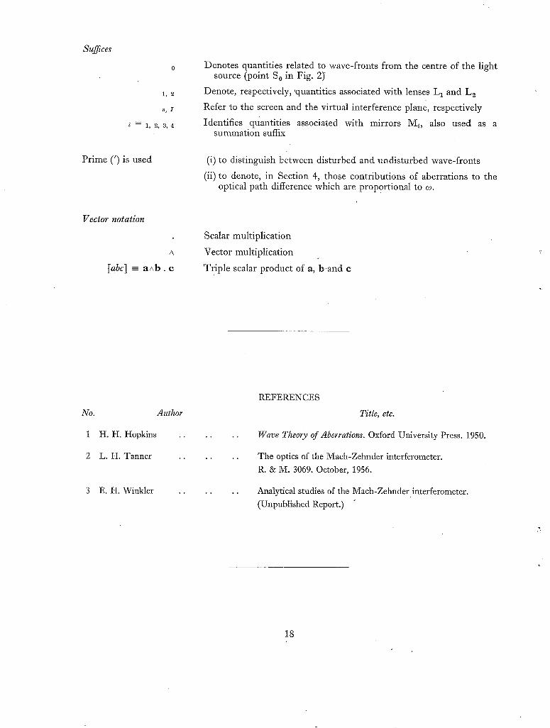
Suffices
1, 2
S, I
i ---- 1, 2, 3, 4
Prime (') is used
Vector notation
A
[abc] - aAb . c
Denotes quantities related to wave-fronts from the centre of the light source (point S o in Fig. 2)"
Denote, respectively, 'quantities associated with lenses L 1 and L~
Refer to the screen and the virtual interference plane, respectively
Identifies quantities associated with mirrors M~, also used as a summation suffix
(i) to distinguish between disturbed and undisturbed wave-fronts
(ii) to denote, in Section 4, those contributions of aberrations to the optical path difference which are proportional to co.
Scalar multiplication
Vector multiplication
Triple scalar product of a, b a n d c
No. Author
1 H .H . Hopkins ..
2 L . H . Tanner ..
3 E .H. Winkler ..
REFERENCES
Title, etc.
Wave Theory of Aberrations. Oxford University Press. 1950.
The optics of the Mach-Zehnder interferometer.
R. & M. 3069. October, 1956.
Analytical studies of the Maeh-Zehnder interferometer. (Unpublished Report.)
18
Focal plane of L
L M,
/ / /
I / ,/ I/ I I I I
M5 I I !i
z /
Fie. 1. Lay-out of an ideal two-beam interferometer.
. . Waxefronhs ~e . F and F f
~-axispos~t: ive M5 M2 F o aria Fo upwards
FIG. 2. Linear representation of the ideal interferometer.
FJe. ~ ~&vefronL F'
- r
P
PR = L = pabh difference a/: P
g,o. 4.
Wavefrong g t
C' , ~DC ri.
P
R P frong F
~,~t'Cs ~ -axis
Fins. 3 and 4. Illustrating notation of Section 2.
Note.--Symbols with a wavy line underneath correspond to bold type in the text.
19
b O
A
. b
L M
/
l///z z~ H/H M Z
. j M~
C
\ \
/
' 5
Irna~e, o f L
\ lma~e, o f N I in M2.
M z a n d ima~m og M3
FIQ. 5- Ideal Twyman-Green interferometer and its linear representation.
~ Pos bion of i t /
• / / / / ~ I wavefronl; in i~he
\ / / / I , a~senooof ~_ h 2 ~ / _ ~ _ L ~ ro~roo~,o~ -
\ /
7 ~ . L Refracbed wavefrorlb .
FIG. 6. Refraction of a plane wave-front.
/ apex and';s direcbed upwards
FIG. 7. Th in pr ism representing effect of • refraction in a wedge-shaped plate.
FiG, 8 (o.) Fig. 8 (b) TanBankia p one [-'~oF bhe lens for khe
Fp_ perfecF, wa,va~ron I" I~g obj~-ck poinL pr F~- aberraJ;ed w&vefronl: 'N
LPrinc.if al FLI an~ a (Sbp) " ~ oF lens) (Im&ge poinL)
View oF.wave~:ronL'. Fp from P Iookin.q a,ion 9 FincipaJ ra~j.~
N.15.__: In fig. 8 (~) V_he plane oF V_he paper conEains Eh~ axis of the lens and Ehe pri0cipal .rag from PJ and is bJne~F-a.ngankiaJ pla,ne"ol = ~ha lens for P-he obje.c,~ poinh_ pt.
FIGS. 8a and 8b. Wave-front aberration produced by a thin lens.
4b
A bcr ra'c.c.d. ~ ~ ~,v,,""~;/~# wa ,,,e,{ro rib5 'bT. ~
UJ( . ~-,
P
~P~rf~cb wav~4:conb5
FIQ. 9. Effect of wave-front aberration on path difference.
~21
#
bO bO
(CollecBincj lens) ( Con]ugabe plane t . , , Lj (. Focal plane, / of L~) ~ of I inin L2L I )and 5 c l. bamera.L2 lens) . . ('bcreens!Z- ,
(InBerference plane') .~
Pi QP FI' P~' - - principal ray of -Lj for objec~ pohB PI
P~ Q PI' P~ ~'P~, P~ ~oP~,
Plane of Fig. IO(a)
(b)
- - undbburbed r~aLj fr~om any source poinB
- - disburbed coherBn~ raLj from b~e same source point, as P~eP I,
- - undisturbed ray from cenBre of source ('princip&J raLj of L 2 for obj'ec~, poinb P~ )
(&-) P.lane of p_2per conb.ain5 axis of L, and princ.ip~l ray__Pa3p~'_P ~,
Plane Z (c) Plane of L r
Flos. lOa to lOc. Collecting and camera lens system.
Publications of the Aeronautical Research Council
A N N U A L T E C H N I C A L R E P O R T S O F T H E A E R O N A U T I C A L R E S E A R C H C O U N C I L ( B O U N D V O L U M E S )
i94i Aero and Hydrodynamics, Aerofoils, Airscrews, Engines, Flutter, Stability and Control, Structures. 63s. (post 2s. 3d.)
194z Vol. I. Aero and Hydrodynamics, Aerofoils, Airserews, Engines. 75s. (post zs. 3d.) Vol. II. Noise, Parachutes, Stability and Control, Structures, Vibration, Wind Tunnels. 47s. 6d. (post is. 9d.)
I943 Vol. I. Aerodynamics, Aerofoils, Airserews. 8os. (post 2s.) Vol. II. Engines, Flutter, Materials, Parachutes, Performance, Stability and Control, Structures.
9os. (post 2s. 3d.) z944 Vol. I. Aero and Hydrodynamics, Aerofoils, Aircraft, Airscrews, Controls. 84s. (post zs. 6d.)
Vol. II. Flutter and Vibration, Materials, Miscellaneous, Navigation, Parachutes, Performance, Plates and Panels, Stability, Structures, Test Equipment, Wind Tunnels. 84s. (post zs. 6d.)
1945 VoL I. Aero and Hydrodynamics, Aerofoils. x3os. (post 3s.) Vol. II. Aircraft, Airserews, Controls. 13os. (post 3s.) Vol. III. Flutter and Vibration, Instruments, Miscellaneous, Parachutes, Plates and Panels, Propulsion.
x3os. (post 2s. 9d.) Vol. IV. Stability, Structures, Wind Tunnels, Wind Turmel Technique. x3os. (post as. 9d.)
z946 Vol. "I. Accidents, Aerodynamics, Aerofoils and Hydrofoils. I68S. (post 3s. 3d.) Vol. II. Airscrews, Cabin Cooling, Chemical Hazards, Controls, Flames, Flutter, Helicopters, Instruments and
Instrumentation, Interference, Jets, Miscellaneous, Parachutes. I68s. (post 2s. 9d.)
I947 Vol. I. Aerodynamics, Aerofoils, Aircraft. z68s. (post 3s. 3d.) Vol. II. Airserews and Rotors, Controls, Flutter, Materials, Miscellaneous, Parachutes, Propulsion, Seaplanes,
Stability, Structures, Take-off and Landing. I68S. (post 3s. 3d.)
Special Volumes Vol. I. Aero and Hydrodynamics, Aerofoils, Controls, Flutter, Kites, Parachutes, Performance, Propulsion,
Stability. I26S. (post 2s. 6d.) Vol. II. Aero and Hydrodynamics, Aerofoils, Airscrews, Controls, Flutter, Materials, Miscellaneous, Parachutes,
Propulsion, Stability, Structures. z47s. (post 2s. 6d:) Vol. III. Aero and Hydrodynamics, Aerofoils, Airserews, Controls, Flutter, Kites, Miscellaneous, Paraehutz*,
Propulsion, Seaplanes, Stability, Structures, Test Equipment. I89S. (post 3s. 3d.)
Reviews of the Aeronautical Research Council 1939-48 3s. (post 5d.) 1949-54 5s. (post 5d.)
Index to all Reports and Memoranda published in the Annual Technical Reports I9o9-1947 R. & M. 2600 6s. (post 2d.)
Indexes to the Reports and Memoranda of the Aeronautical Research Council Between Nos. 2351-24-49 R. & M. No. 2450 2s. (post 2d.) Between Nos. 245x-2549 R. & M. No. 255o 2s. 6d. (post 2d.) Between Nos. zS5z-2649 R. & M. No. 2650 zs. 6d. (post 2d.) Between Nos. 2651-2749 R. & M. No. 2750 2s. 6d. (post 2d.) Between Nos. 2751-2849 R. & M. No. 2850 2s. 6d. (post zd.) Between Nos. 2851-2949 R. & M. No. 295o 3s. (post 2d.)
HER MAJESTY'S STATIONERY OFFICE from the addresses overleaf
. 4
R. & ~M. No. 3173
© Croum copyright x96I
Printed and published by HBa MAJESTY'S STATIONERY OFFICE ~'
To be purchased from York House, Kingsway, London w.c.2
423 Oxford Street, London w. i I3A Castle Street, Edinburgh 2
xo9 St. Mary Street, Cardiff 39 King Street, Manchester 2
5o Faiffax Street, Bristol x 2 Edmund Street, Birmingham 3
8o Chichester Street, Belfast i or through any bookseller
Printed in England
R. & M. No. 3173
S.O. Code~No. 23-3r73