Embed Size (px)
Citation preview
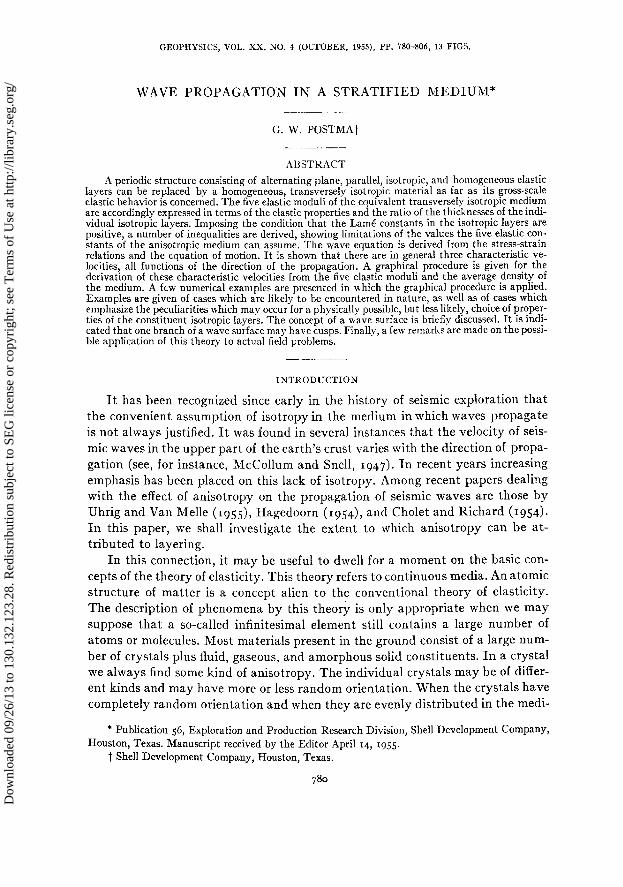
GEOPHYSICS, VOL. XX, NO. 4 (OCTOBER, 1955), PP. 780406, 13 FIGS.
WAVE PROPAGATION IN A STRATIFIED MEDIUM*
G. W. POSTMAt
ABSTRACT
A periodic structure consisting of alternating plane, parallel, isotropic, and homogeneous elastic layers can be replaced by a homogeneous? transversely isotropic material as far as its gross-scale elastic behavior is concerned. The five elastic moduli of the equivalent transversely isotropic medium are accordingly expressed in terms of the elastic properties and the ratio of the thicknesses of the indi- vidual isotropic layers. Imposing the condition that the LamC constants in the isotropic layers are positive, a number of inequalities are derived, showing limitations of the values the five elastic con- stants of the anisotropic medium can assume. The wave equation is derived from the stress-strain relations and the equation of motion. It is shown that there are in general three characteristic ve- locities! all functions of the direction of the propagation. A graphical procedure is given for the derivation of these characteristic velocities from the five elastic moduli and the average density of the medium. A few numerical examples are presented in which the graphical procedure is applied. Examples are given of cases which are likely to be encountered in nature, as well as of cases which emphasize the peculiarities which may occur for a physically possible, but less likely, choice of proper- ties of the constituent isotropic layers. The concept of a wave surface is briefly discussed. It is indi- cated that one branch of a wave surface may have cusps. Finally, a few remarks are made on the possi- ble application of this theory to actual field problems.
INTRODUCTION
It has been recognized since early in the history of seismic exploration that the convenient assumption of isotropy in the medium in which waves propagate is not always justified. It was found in several instances that the velocity of seis- mic waves in the upper part of the earth’s crust varies with the direction of propa- gation (see, for instance, McCollum and Snell, 1947). In recent years increasing emphasis has been placed on this lack of isotropy. Among recent papers dealing with the effect of anisotropy on the propagation of seismic waves are those by Uhrig and Van Melle (1955), Hagedoorn (1954), and Cholet and Richard (1954). In this paper, we shall investigate the extent to which anisotropy can be at- tributed to layering.
In this connection, it may be useful to dwell for a moment on the basic con- cepts of the theory of elasticity. This theory refers to continuous media. An atomic structure of matter is a concept alien to the conventional theory of elasticity. The description of phenomena by this theory is only appropriate when we may suppose that a so-called infinitesimal element still contains a large number of atoms or molecules. Most materials present in the ground consist of a large num- ber of crystals plus fluid, gaseous, and amorphous solid constituents. In a crystal we always find some kind of anisotropy. The individual crystals may be of differ- ent kinds and may have more or less random orientation. When the crystals have completely random orientation and when they are evenly distributed in the medi-
* Publication 56, Exploration and Production Research Division, Shell Development Company, Houston, Texas. Manuscript received by the Editor April 14, 1955.
t Shell Development Company, Houston, Texas.
Dow
nloa
ded
09/2
6/13
to 1
30.1
32.1
23.2
8. R
edis
trib
utio
n su
bjec
t to
SEG
lice
nse
or c
opyr
ight
; see
Ter
ms
of U
se a
t http
://lib
rary
.seg
.org
/
WAVE PROPAGATION IN A STRATIFIED MEDIUM 781
urn, the elastic behavior of the whole complex may be described as isotropic. This conception implies that the smallest elements of matter to be considered contain a good sampling of all constituent parts. When for some reason or other the orien- tation is not completely at random, a certain measure of anisotropy will be found. For example, metamorphic rocks may exhibit considerable anisotropy. Or the manner in which the materials are formed and the way their constituents are arranged during the geological processes involved in their formation may result in a seismically anisotropic medium.
A layered structure can be regarded as an anisotropic medium of the latter type. We shall, in this paper, consider a formation consisting of alternating plane, parallel layers of materials which on a smaller scale can be regarded as isotropic. In considering such a material as a homogeneous anisotropic medium, we must suppose that an elementary volume contains a large number of layers. The theory then leads to the type of anisotropy known as transverse isotropy.
In order to find a connection between the properties and thicknesses of the isotropic layers and the equivalent homogeneous, transversely isotropic medium, we may proceed in two ways. One way, which we shall follow here, involves the establishment of stress-strain relations for an elementary portion of the layered medium. With the help of these relations and the equations of motion, we can derive equations describing the propagation of plane waves. The velocity of these plane waves will turn out to be a function of the direction of the normal to the wave fronts (or, as the case may be, planes of equal phase).
The second approach is to consider plane harmonic waves in the isotropic layers (Thompson, 1950). These waves are reflected and transmitted at the vari- ous interfaces. It is possible to assign a phase velocity to the resultant wave mo- tion. In the limit when the ratio of the thicknesses of the layers to the wave- lengths approaches zero, the phase velocity should approach the velocity of propagation found by the method described in the previous paragraph. This expectation has been verified for the case of plane wave propagation perpendicu- lar to the layering.
The second kind of derivation has the advantage of showing the degree of approximation involved with finite ratios of layer thicknesses to wavelength. The first kind has the advantage of simplicity, but yields only a limiting value.
Our calculations are restricted to the case where there are only two kinds of isotropic layers, which alternate and therefore form a periodic structure. It is realized, of course, that such periodicity would only rarely occur in nature, but this model will serve the main purpose of this paper, namely to develop a basis for estimating the degree of anisotropy which can be attributed to a layered structure of sediments.
After this paper was originally written as a company report for the Bataafsche Petroleum Maatschappij and the Shell Oil Company, an article was published by Risnichenko (1949) developing essentially the same type of argument. The writer feels justified in publishing this paper nevertheless, first because it covers
Dow
nloa
ded
09/2
6/13
to 1
30.1
32.1
23.2
8. R
edis
trib
utio
n su
bjec
t to
SEG
lice
nse
or c
opyr
ight
; see
Ter
ms
of U
se a
t http
://lib
rary
.seg
.org
/
782 G. W. POSTMA
a somewhat wider range than that by Risnichenko, and secondly because the
latter’s paper is in Russian, which makes it less accessible.’
STRESS-STRAIN RELATION IN A TRANSVERSELY ISOTROPIC AND
IN A STRATIFIED MEDIUM
In a transversely isotropic medium, all directions making the same angle
with a certain axis of symmetry are equivalent. Taking the axis of symmetry as
the z axis and supposing Hooke’s law to be valid, it is then required that the co-
efficients in the relations between the components of stress and strain are in-
variant with respect to rotations of the coordinate system around the z axis.
When we express, in the notation of Love (1934, art. 66), Hooke’s law by the
following set of equations
X, = cllezz + c12eyy + c13ets + c14euz + c16etz + c16ezy
Y, = c41ezz + c42e,, + c43ezr + c44eyz + c46ezz + c46ezs (1)
. . . . . , . . . . . . . . . . . . . . . .
in which expressions cij=Cji(i, j== I, z - * * , 6), the invariance mentioned leads
to the fOllOwhg array of the CO&kkntS of equation (I) (LO%, 1934, art. 109) :
Cl1 Cl2 Cl3 0 0 0
Cl2 Cl1 Cl3 0 0 0
613 Cl3 c33 0 0 0
(2) 0 0 0 644 0 0
0 0 0 0 644 0
C11-G12 0 0 0 0 o------’
2
The-meaning of the various symbols is:
X,= the normal component of the traction across a surface element perpendicular
to the x axis, etc.
Y,= the tangential component parallel to the y axis of the traction across a surface
element perpendicular to the z axis, etc.
We observe that Y,=Z, (Love, 1934, art. 47);
au av aw e ZZ=-;
ax eyy = - ;
aY ezr = - ;
a2
aw av at4 aw av au e - ‘a - aY
_+G; e,,=z+G; ezu=z+--j aY
1 The reader is also referred to a paper on the same subject by White and Angona (1955) which was published shortly after this paper was submitted.-The E&w.
Dow
nloa
ded
09/2
6/13
to 1
30.1
32.1
23.2
8. R
edis
trib
utio
n su
bjec
t to
SEG
lice
nse
or c
opyr
ight
; see
Ter
ms
of U
se a
t http
://lib
rary
.seg
.org
/
WAVE PROPAGATION IN A STRATIFIED MEDIUM 783
where U, D, w are the components of the displacement. ezz is the linear dilatation of line elements in the direction of the x axis in the
unstrained state. eUz is the decrease of the angle between two line elements, which are parallel
to the y and z axes in the unstrained state (Love, 1934, art. IO).
In a transversely isotropic medium, five coefficients (in our case cll, c12, c13, ~$3, CU) are independent, compared with two in an isotropic medium, where cl1 =&=x+211; clz=c13=h; c44=/.L.
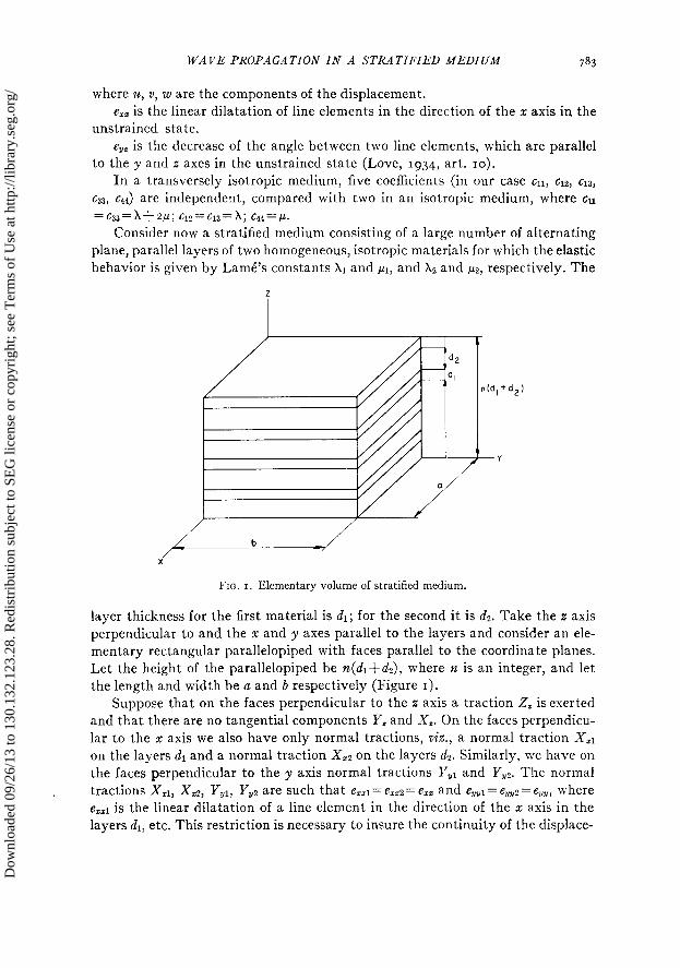
Consider now a stratified medium consisting of a large number of alternating plane, parallel layers of two homogeneous, isotropic materials for which the elastic behavior is given by Lame’s constants X1 and pl, and X2 and p2, respectively. The
--Y
FIG. I. Elementary volume of stratified medium.
layer thickness for the first material is 4; for the second it is a$. Take the z axis perpendicular to and the x and y axes parallel to the layers and consider an ele- mentary rectangular parallelopiped with faces parallel to the coordinate planes. Let the height of the parallelopiped be n(dl+&), where n is an integer, and let the length and width be a and b respectively (Figure I).
Suppose that on the faces perpendicular to the z axis a traction 2, is exerted and that there are no tangential components Y, and X,. On the faces perpendicu- lar to the x: axis we also have only normal tractions, viz., a normal traction X,r on the layers dl and a normal traction X,2 on the layers dz. Similarly, we have on the faces perpendicular to the y axis normal tractions Y,r and YUz. The normal tractions Xzr, Xz:, YV1, Y,, are such that ezrl = ez22 = ezz and e,,l= eUu2 = e,,, where ezzl is the linear dilatation of a line element in the direction of the x axis in the layers dr, etc. This restriction is necessary to insure the continuity of the displace-
Dow
nloa
ded
09/2
6/13
to 1
30.1
32.1
23.2
8. R
edis
trib
utio
n su
bjec
t to
SEG
lice
nse
or c
opyr
ight
; see
Ter
ms
of U
se a
t http
://lib
rary
.seg
.org
/
784 G. W. POSTMA
ment as a function of the radius vector. The linear dilatation of a linear element parallel to the z axis in the dr layers is errl, in the dz layers it is eu2. In general
e,,l f err2.
In the first isotropic medium Hooke’s law gives:
X,I = (XI + wdezz + Xeh, + Xlerzl
Y,I = Xvzzz + (XI + wJe,, + Aled
2, = Xlezz + Ale,, + (Xl + 2&etzl.
(3”)
The equations for the second isotropic layer are obtained by replacing the index I by the index 2. We shall designate this set of equations as (gb). The average traction on a face perpendicular to the x axis becomes
and on a face perpendicular to the y axis,
Y, = &Y,, + &Y,z
d, + dz -’
(4)
while the traction on the face perpendicular to the z axis is Z,. From (3a), (gb), and (4) we find:
(dr + &)X, = ezz[&(A1 + 21.11) + &(Xz + a~)]
+ e,,(X& + &&) + eEeJ& + ezs2M2
(& + &)I’, = ezz(XA + X&J + e,,[&(X1 + 2~1) + &(X2 + a&] (5)
+ ezEJ& + e,A&
We define erz by
(4 + d2)ezE = &ezzl + &ezr2, (6)
where e,, is the over-all dilatation of a linear element parallel to the z axis, which contains an equal number of sections through the layers dl and dl.
From the last equations of (3a) and (3b) and (6), we find:
(& + &)(X2 + 2p2)ezz - (Xl - A,)(e,, + e,,)& eztl =
(4 + &)(A1 + +l)ezn + (Xl - U(e,, + e,,)& ezz2 =
Dow
nloa
ded
09/2
6/13
to 1
30.1
32.1
23.2
8. R
edis
trib
utio
n su
bjec
t to
SEG
lice
nse
or c
opyr
ight
; see
Ter
ms
of U
se a
t http
://lib
rary
.seg
.org
/
WAVE PROPAGATION IN A STRATIFIED MEDIUM 785
Substituting this result in (5) we arrive at:
x =e (d,+d2)2(Xl+2~L1)(X2+2~2)+dld21 [(x~+2~~)-((xz+2~cz)]~-(xi-x2)~~ Z ZI
D
+h
X1X2(dl+d2)2+2(XIdl+X2d2)(y2dl+~ld2)
D
+eZZ GL+a ~Mlcb+ w2)+Xzrd2(X1+ z/L,>]
D
y =e ~1~2(~l+~2)2+4~ldl+X2d2)(p2dl+pld2)
Y Zt D
z =(e I 21s
+ eyy
) (&+dd [h,dl(X2+2~2)+Xzdz(X1+2~1) 1 D
+ezz
(d,+d2)2(X1+2~L1)(X2+2)*2) .
D
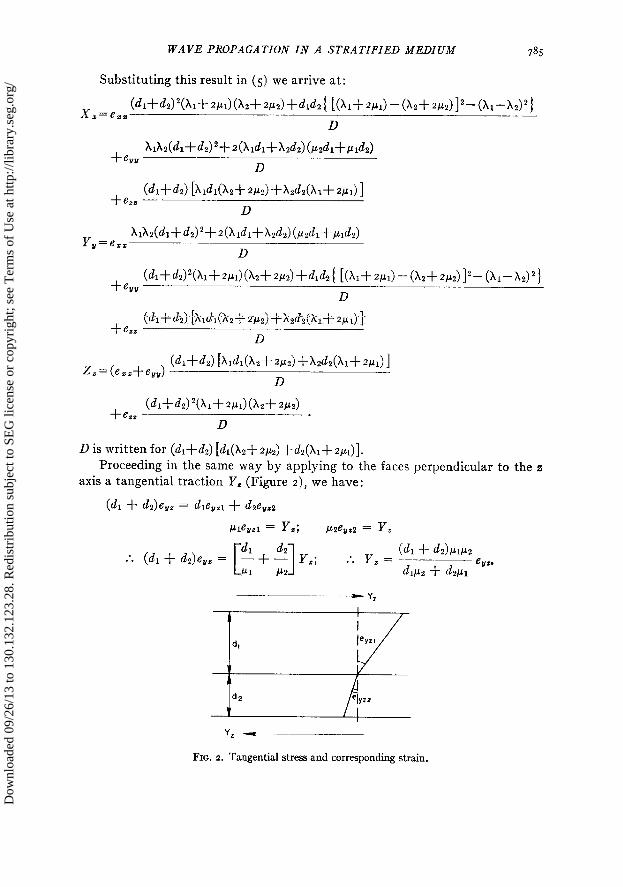
D is written for (&-I-d2) [d~(X23‘2~~)fd~(X1+2~l)]. Proceeding in the same way by applying to the faces perpendicular to the z
axis a tangential traction Y, (Figure 2), we have:
(A + d2)e,, = &eysl + d2eyr2
~leffzl = Y,; k62eyE2 = Y,
:. (dl + d2)e,, = 5 + d2 Y,; [ 1 y = (4 + dZ)PlP2 :. E
Pl 112
d lP2
+ d ~ eun. 21
FIG. 2. Tangential stress and corresponding strain.
Dow
nloa
ded
09/2
6/13
to 1
30.1
32.1
23.2
8. R
edis
trib
utio
n su
bjec
t to
SEG
lice
nse
or c
opyr
ight
; see
Ter
ms
of U
se a
t http
://lib
rary
.seg
.org
/
786 G. M. POSTMA
Similarly we find:
(d, + d&h = [ 1 5 + 2 x,. :. * x = cdl+ awz - ezz.
Pl PZ h2 + d2pl
Finally applying a tangential force X,radl to the faces perpendicular to the
y axis of the dr layers and a tangential force X,Zadz to the corresponding faces of
the dz layers and realizing that ezyl must be equal to eZy2 in order to insure the
continuity of the displacement, we find that pleZy = X,r; p2eZy = Xu2, so that when
X, is the average tangential traction on the parallelopiped,
Xddl + dz) = X,1& + X,2d2 = e,,(pldl + p2d2) :. x, = Ccl4 + w-A
dl+d, ezu’ Comparing these results with (2) we see that, when viewed on a proper scale,
the layered medium may be considered as transversely isotropic. We find:
~12=; { (dl+dz)2X1Xz+2(Xldl+X2d2)(C(2dl+~Clld2))
CIS=; {Cdl+&) [Xldl(X2+2/1z)+X2dz(X1+2~1)] ]
cs=;{ (d,+dp)‘(X1+2~CL1)(X2+2~C12)}
(7)
(dl+&)/.w c44=
dlpCcz+dzpl
/.4l&+/.dz
'w= dl+d2 *
Between cll, c12, and ~66 there exists the relation c66= (c~~-c~~)/~, as becomes
apparent by substitution. Here also there are five independent coefficients.
The values of cl1 and c33 are in agreement with those found by Risnichenko (1949).
LIMITATIONS OF THE VALUES OF THE COEFFICIENTS OF A LAYERED MEDIUM
The coefficients ~1, c12, c13, 663, ~44, c66, for a general transversely isotropic me-
dium are subject to some restrictions. Rudzki (IgII) gives the following in-
equalities:
611, c33, c44, C66 > 0,
Cl1 - c44 > 0 611 - c66 > 0 C33(Cll - C66) > Gl32
c33 - c44 > 0 G33 - G66 > 0.
Dow
nloa
ded
09/2
6/13
to 1
30.1
32.1
23.2
8. R
edis
trib
utio
n su
bjec
t to
SEG
lice
nse
or c
opyr
ight
; see
Ter
ms
of U
se a
t http
://lib
rary
.seg
.org
/
787 WAVE PROPAGATION IN A STRATIFIED MEDIUM 787
We shall now investigate the conditions satisfied by the coefficients CII, 612.
c13, c33, c44, CM as defined by equation (7). We shall assume that XI, XZ, ~1, and CLZ
are positive quantities$ cl , c13, c33, c44, cG6 are seen to be positive. Since cn= 612
+2c66, it is evident that CU~>O. Furthermore, c~I>c~L~.
I I
633 - ~44 = Cdl + d2) - >o
dl & - dl
L Xl + 21.11
+ -+!?
x2 + 2!J2 Pl P!2 ,
dldz (Ml - d2 c44 - C66 = - ~ 5 0.
dl + d2 &Cc2 + d2p1
The equaiity sign is valid when ,.L~=P~. In that case ~44 = cB6 = p1 = pZ = p.
Since cll- cc6 > 0, certainly cl1 - cq4> 0.
We can choose the constants at our disposal, which are dl/dz, X1, pl, x2, p2, so
that CB- CM <o. For instance, letting them have the respective values I, x1, o, 0, 4X1, we get:
& + & PI& + /.4 c33 - C66 =
dl d2 - & + dz
+
Xl + z/J1 x2 + 2l.42
2 4x1 --_= - x1” < 0.
$ + ;_ 2 9
1 1
This is in contradiction with one of the conditions given by Rudzki.
The values chosen are not likely to occur in nature, but they are physically
possible. The expression (cll-- c~~)(G~~- Cam) - (t13+~44)2 will prove to be important.
After a somewhat lengthy calculation, which will not be repeated here, we find
that
(G11 - G44)(C33 - c44) - (Cl3 + c44j2 =
&d2h - PZ)~(& + ELI)(~ + ~2)
Cdl/a + d2d [&(A2 + 2~2) + d2@1 + w>1
which is always larger than zero, except for pl= p2, in which case it becomes zero. Equally important is the expression
Gil+ 633 611 - 2613 + 633
~- - 644 - (613 + 644) = - 2644.
2 2
t For the isotropic materials in the earth this is always the case. It should be mentioned, however, that the requirements for stability are less stringent. These are ~>o and X> -a/~.
Dow
nloa
ded
09/2
6/13
to 1
30.1
32.1
23.2
8. R
edis
trib
utio
n su
bjec
t to
SEG
lice
nse
or c
opyr
ight
; see
Ter
ms
of U
se a
t http
://lib
rary
.seg
.org
/
788 G. W. POSTMA
On substitution of the values in (7) we find that
Cl1 - 2613 + c33 -- ~ - 2c44
2
= 2 & (kl - P2)2
A02 + P2) + dz(X1 + PI)
[ah2 + w2) + d2(X1+ 21*1)](&p2 + d2Pl) z O*
The equality sign corresponds to the special case pL1=p2. The expression
_A!!? (p1 _ & ~ (A* + /Jr) - 02 + I-12)
Cl1 - c33 = dl + d2
m2 + w2) + dz(X1 + Wl)
may be positive or negative : positive when ,ui> p2 and simultaneously X1+pl > x2
-l-~lz, or when M<FLZ and simultaneously Xr+/.~l<X~+p~; and negative when
M>LLZ while X~+~*~<XZ+M or when N<M while XI+~1>X2+p2.
When either M= M or X~+M = X2+~2, cl1 equals c33. c~~/c~~ can have arbitrarily large values as can be seen from the following expression:
611 4&d?
- = I + (dl + d2)2
(Xl + Pl) - 02 + P2)
c33 h - g2) -(xl + 2X2)(X2 + 2/L*) .
Let Xl=& and /J~=~PLZ, a condition that is always possible, in which case both media have the same Poisson’s ratio; then
611 d&2 /*2(X2 + P2) (n - I)” -
633 --+ I + (~5 + d2)2 (X2 + 2~2)~ -i--’
which for n--too grows beyond any limit.
It can be shown that (&c~~) > 4. For example, if p1 = X2= o and dl = d2, we have
Cl1 Xl - P2 _~~_-_~
633 2x1
I+!$
2
For the case pr= ,uL~ = p we have the remarkable result that
dl dz
Xl - +x2--
& + d2 Xl + 2P x2 + 2/J Cl1 = c33 =
dl d2 ;
612 = Cl3 =
dl d2 --; ---+p ------+p Xl + 21.1 AZ + 2P Xl + 2P X2 + 2P
644 = 666 = I*.
The medium behaves as an isotropic medium in which
& dr Xl ~
Xl + 2/J
+x2---
12 + 2/J A=_
& d2
-+----- x1 + 2P x2 + 2P
Dow
nloa
ded
09/2
6/13
to 1
30.1
32.1
23.2
8. R
edis
trib
utio
n su
bjec
t to
SEG
lice
nse
or c
opyr
ight
; see
Ter
ms
of U
se a
t http
://lib
rary
.seg
.org
/
WAVE PROPAGATION IN A STRATIFIED MEDIUM 789
PLANE WAVES IN A LAYERED MEDIUM
Wave propagation in an anisotropic medium in general and in a transversely
isotropic medium in particular has been treated by various authors. Love (1934,
art. 208) devotes a few pages to this subject in his book on elasticity. Stoneley
(1949) has considered the case of transverse isotropy in more detail. In an un-
published report by Hazebroek for the Bataafsche Petroleum Maatschappij
on wave propagation in an anisotropic medium, reference was made to the paper
by Rudzki (rgrr), to whom we are indebted for a thorough investigation. Un-
fortunately, this paper is not readily accessible.
We shall derive the wave equation for waves in a transversely isotropic
medium from the stress-strain relations (2) and the equations of motion.
The equations of motion are
ax, dX, dX,
(8) az, az, az, a2rel -+-.+yq= ax ay y$’
Substituting in these equations the expressions for the components of the
stress as given by Hooke’s law (equation (2)), we get:
ah a*u a*u Cl1 G + Cl58 -y + 644 ---$ + (Cl1 - mJ
aY ?- + (613 + 644) g = P 2 axaY
a% a221 E+
a*v a*2e, (Cl1 - 4 - + GE36 ~ + Cl1
axaY ax* .2 c44 -g + (Cl3 + c44) __ =
aYa2 P $ (9)
a*v (Cl3 + c44) -g + (Cl3 + c44) -
a2w a2W a2W a2W *” aYas
+ c44 G + 644 -; + c33 7 = p ---$ * aY a2
The value of the density p is given by p= (pd+p&/(&+&) where pl and pz are the respective densities in the dl and d$ layers.
We now try a solution representing plane waves; we may restrict ourselves
to waves perpendicular to the coordinate plane y=o, for the axial symmetry
around the z axis guarantees the similarity of wave fronts perpendicular to any
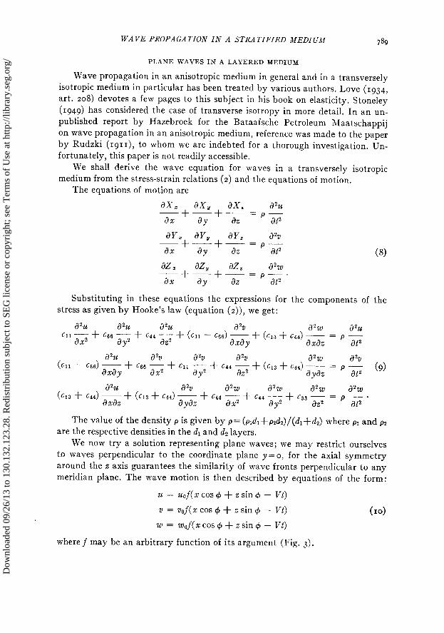
meridian plane. The wave motion is then described by equations of the form:
24 = u&xcos++zsin+- Vt)
v = vJ(xcos++zsin+ - Vt) (4
w = wJ(xcos++zsin+- Vt)
wheref may be an arbitrary function of its argument (Fig. 3).
Dow
nloa
ded
09/2
6/13
to 1
30.1
32.1
23.2
8. R
edis
trib
utio
n su
bjec
t to
SEG
lice
nse
or c
opyr
ight
; see
Ter
ms
of U
se a
t http
://lib
rary
.seg
.org
/
790 G. W. POSI‘MA
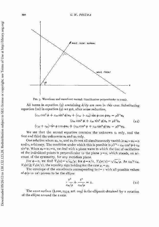
FIG. 3. Wavefront and wavefront normal. Stratification perpendicular to z-axis.
All terms in equation (9) containing a/ay are zero in this case. Substituting equation (IO) in equation (9) we get, after some reduction,
(611 cos2 $J + 644 sin2 ~$)zLo + (613 + 644) sin C#I cos 4200 = pV2u0
(666 cos2 4 + c44 sin2 4)vo = pVzoO (II)
(cl3 + 644) sin + cos f@g + (c44 cos2 4 + 633 sin2 $)mo = pV2w0.
We see that the second equation contains the unknown vo only, and the first and third the unknowns ug and wg only.
One solution where ~0, “~0, and wo do not all simultaneously vanish is zcg = wg = o and 00 arbitrary. The condition under which this is possible is pV2= ~66 COS~C#I+C~~ sin2 4. When u. = wo = o, we deal with a plane wave in which the line of oscillation of the individual points is perpendicular to the plane y=o, which stands, on ac- count of the symmetry, for any meridian plane.
For q5 = o, we find V3(o) = d/~~~/p; for 4 = ‘IF/Z, V3(a/ 2) = dc44/p. As c66 >= cq4, V3(o) 2 1/3(~/2), the equality sign holding for the case PI= ~2.
The envelope of the wavefronts correspondingq to t = I with all possible values of +(o to 2~) proves to be the ellipse
x? 22 -+ __ = I.
666/P C44IP
(12)
The wave surface (Love, 1934, art. 209) is the ellipsoid obtained by a rotation of the ellipse around the z axis.
Dow
nloa
ded
09/2
6/13
to 1
30.1
32.1
23.2
8. R
edis
trib
utio
n su
bjec
t to
SEG
lice
nse
or c
opyr
ight
; see
Ter
ms
of U
se a
t http
://lib
rary
.seg
.org
/
WAVE PROPAGATION IN -4 STRATIFIED MEDIUM 79’
Other solutions can be found in which zlo=o, and ZLO#O, wo#o, corresponding to plane waves where the points of the medium oscillate along straight lines in the plane y=o. These solutions exist when the determinant vanishes, viz.
cl1 cos2 C$ + cq4 sin2 I$ - pV2 (613 + 644) sin 9 cos 4 = 0.
(CM + ~44) sin d cos 9 c44 cos? + + c33 sin2 4 - pV2 (13)
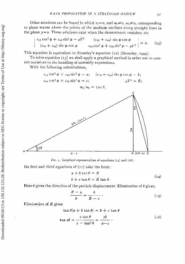
This equation is equivalent to Stoneley’s equation (IO) (Stoneley, 1949). To solve equation (13) we shall apply a graphical method in order not to com-
mit ourselves to the handling of unwieldy expressions. With the following substitutions,
cl1 cos2 4 + c44 sin2 $J = a; (cl3 + c44) sin + cos 4 = b;
c44 cos2 6 + c33 sin2 + = G; pV2 = R;
wo/uo = tan 8,
FIG. 4. Graphical representation of equations (IS) and (16).
the first and third equations of (II) take the form:
a+btanB= R
b + c tan 0 = R tan 0. (14)
Here 0 gives the direction of the particle displacement. Elimination of 0 gives:
R-a b PC ___.
b R-C (15)
Elimination of R gives
tan e(a + b tan 0) = b + c tan 0
2 tan e zb (16) tan 28 = =-_.
I - tan2 e a-c
Dow
nloa
ded
09/2
6/13
to 1
30.1
32.1
23.2
8. R
edis
trib
utio
n su
bjec
t to
SEG
lice
nse
or c
opyr
ight
; see
Ter
ms
of U
se a
t http
://lib
rary
.seg
.org
/
G. W. POSTMA 792
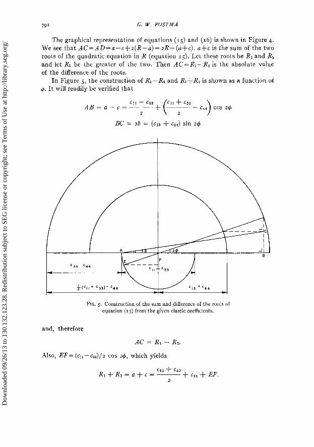
The We see
graphical representation of equations (IS) and (16) is shown in Figure 4. that AC=AD=a-c+z(R-a)=zR--((a+~). ufc is the sum of the two
roots of the quadratic equation in R (equation 15). Let these roots be RI and Rz and let RI be the greater of the two. Then AC= RI- Rz is the absolute value of the difference of the roots.
In Figure 5, the construction of RI- Rz and RI&R, is shown as a function of .+x It will readily be verified that
AB = Cl1 - c33
+
(
Cl1 + c33 a-c= __- ~ - 644 cos 24
2 2
BC = 28 = (~13 + c& sin 2+
-I- -,
FIG. 5. Construction of the sum and difference of the roots of equation (IS) from the given elastic coefficients.
and, therefore
AC = RI - Rz.
Also, EF = (cll-- 4/z cos 24, which yields
Rl+Rz=u+c= Cl1 + 633
_____ + 644 -t EF. 2
Dow
nloa
ded
09/2
6/13
to 1
30.1
32.1
23.2
8. R
edis
trib
utio
n su
bjec
t to
SEG
lice
nse
or c
opyr
ight
; see
Ter
ms
of U
se a
t http
://lib
rary
.seg
.org
/
WAVE PROPAGATION IN A STRATIFIED MEDIUM 793
In the previous section we saw that (c~~+c~~)/z-c~~>c~~+c~~. Therefore, the major axis of the ellipse described by C, when 4 varies from o to r, is always horizontal. The largest value of RI- Rz occurs when += o or 7r/2, corresponding to cl1 > c33 or c33> cu.
The sum and difference of the roots being known, RI and Rz can be deter- mined without difficulty. The construction also gives 0 as a function of $J. The values of 0 corresponding to RI and Rz differ by an amount a/2. When a value 8 satisfies equation (16), this equation will also be satisfied by 0+(7r/2). To deter- mine which of the two values of 0 corresponds to RI, we consider a small value of 9. Then a-cll; b-(~r~+c4~) ; G-c44.
According to equation (r6) we~have
tan 20 - (Cl3 + 644124
Cl1 - 644
for which the following two solutions are of interest:
Cl3 + 644 613 + c44
h-+p and Cl1 - 644
@,-;+,---. Cl1 - 644
Let 8=&; then the first equation of (14) gives R-x11. Let O=Og; then
Cl1 - 644 tan O2 - -
dCl3 + c44)
The first equation of (14) yields
R - ~11 - +(c13 + ~14)
611 - c44
dCl3 + c44)
= c44.
The same result can be obtained from the second equation. So for 4 = o.
RI = cll, % = o, and Ii2 = c44, 0 = a/2.
For +=7r/2,
RI = c33, 0 = r/2, and Rz = ~44, 0 = T.
The wave with the largest normal velocity, therefore, resembles a longitudi- nal wave, while the slower wave resembles a transverse wave. The waves are purely longitudinal or transverse in the directions $=o and 7r/2, but not in general in other directions.
For the velocities we find VI(o) = ~‘\/c~r/p; Vr(?r/z) = ~‘\/c~~/p; VZ(O) = v’c~~/~;
J72(7r/2) = d&/P. We write equation (13) in the form:
c11+c33 611- c33
-----+~ cos 24 )I
+ c44
c11+c33 ( Cl1 - c33 p+------ cos 24
2 2 2 2
Dow
nloa
ded
09/2
6/13
to 1
30.1
32.1
23.2
8. R
edis
trib
utio
n su
bjec
t to
SEG
lice
nse
or c
opyr
ight
; see
Ter
ms
of U
se a
t http
://lib
rary
.seg
.org
/
794 G. W. POSTMA
1 + -[(CII - C44)(633 - 644) - (613 + c44)2] sin2 2fJ1 = 0.
4
:. (X-ccqq) m+c33 Cl1 - 633
R-------------- cos 24
2 2 >
= -~L(c~~-s4)(c33-c44~-(~~3+~44)~] sin2 24. (13”)
From the results in the previous section, we see that the right-hand member is always negative when p1#p2 and when4#0 or r/2. Since
Cl1 + 633 Cl1 - 633
c44 < -----++ cos 2+
2 2
for all values of 4, the roots must lie between the following limits
Cl1 + c33 644 s Rz < R1 5 -___
611 - 633 +p cos 24.
2 2
The two roots RI and R2 are always distinct, for RI-- R2 never vanishes when 4 changes from o to r/2 (Figure 5).
In the exceptional case that ~1=~2, the second member becomes zero and the roots are R1 = cu= ~33 and R2 = ~4. They are independent of 4. The wave surfaces prove to be spheres with radii
NUMERICAL EXAMPLES
A few examples have been circulated on the basis of data from the literature Eve and Keys (1929, p. 188) give the following numerical values for elastic
constants of typical earth materials: Limestone:
p = 2.69-2.72; p = (2.1-3.0)10”;
K = (3.7-5.7)I01*; (T = 0.25-0.28 (c.g.s. units).
Sandstone :
p = 2.3 (?); p = 0.61. 10~‘;
K = 1.25, IO”; u = 0.29 (c.g.s. units).
K is the bulk modulus; K = A+$*; u is Poisson’s ratio. For a demonstration of the anisotropy under realistic conditions, we take the
dr layers to be limestone and the dz layers sandstone, with the following parame- ters :
Dow
nloa
ded
09/2
6/13
to 1
30.1
32.1
23.2
8. R
edis
trib
utio
n su
bjec
t to
SEG
lice
nse
or c
opyr
ight
; see
Ter
ms
of U
se a
t http
://lib
rary
.seg
.org
/
WAVE PROPAGATION IN A STRATIFIED MEDIUM 795
P1 = 2.7; p1 = 2.5' 10’1;
from which
V,I = j.44 km-set-l;
PZ = 2.3; /.42 = 0.6. IO”;
from which
VP2 = 2.95 km-sec_I;
Case I
X1 = 3.0.10”; u1 = 0.273,
V,I = 3.04 km-set-l.
AZ = 0.8~10”; u2 = 0.286,
k’82 = 1.62 km-set-‘.
Let dl= I ; dz= 3. (See Figure 6.) We find
~11 = 3.36. IOI~ (dyne/cm*)
Cl2 = I.zI’Io*I
Cl3 = 0.97 101’
p = 2.4
~33 = 2.46. IOI~
c44 = 0.74 1011
666 = 1.08.10*1
- - - = 3.73 km-set-l; = 3.21 km-set-I; = 1.76 km-set-I;
-
d 666 - = 2.12 km-set-l. P
Then we obtain the following data by means of the construction in Figure 5:
4 Vl 0 (z direction) 3.73 rl24 3.71 T/I2 3.67 r/s 3.62 p/6
SK/24
3.53
r/4 3.45 3.36
7x/24 3.29 r/3 2.24
3*/8 3.22 F/12 3.21 I 1?r/24 3.21 r/2 3.21
Case 2
Let dl= 3; a$= I. (See Figure 6.)
V2 I.76 1.79 1.82 I.87 1.91
I.97 2.00
2.00
I.94 1.89 1.84
I.79 1.76
~11 = 6.25. ION* (dyne/cm2)
cI2 = 2.19.10~~
613 = I.74. IOIl
p = 2.6
va 2.12 2.12 2.10 2.07 2.04 2.00
I.95 1.89 1.86 I.82
I.79 1.76 1.76
(km-se@)
c33 = 4.57. roll
644 = 1.40.10~~
c66 = 2.03.10~~
Dow
nloa
ded
09/2
6/13
to 1
30.1
32.1
23.2
8. R
edis
trib
utio
n su
bjec
t to
SEG
lice
nse
or c
opyr
ight
; see
Ter
ms
of U
se a
t http
://lib
rary
.seg
.org
/
6
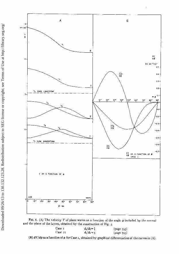
FIG. 6. (A) The velocity V of plane waves as a function of the angle + included by the normal
and the plane of the layers, obtained by the construction of Fig. 5.
Case I dJdz= % (page 795)
Case II dJ& = 3 (page 795)
(B) dV/d$ as a function of 4 for Case I, obtained by graphical differentiation of the curves in (A).
Dow
nloa
ded
09/2
6/13
to 1
30.1
32.1
23.2
8. R
edis
trib
utio
n su
bjec
t to
SEG
lice
nse
or c
opyr
ight
; see
Ter
ms
of U
se a
t http
://lib
rary
.seg
.org
/
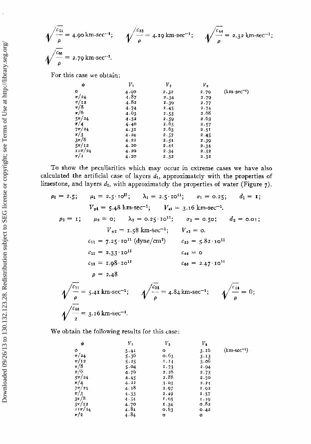
- - J Cl1 633
- = 4.90 km-set-1; - = 4. I 9 km-set-l ; P P
-
J G.6 - = 2.79 km-set-l. P
For this case we obtain:
G Vl 0 r/24
4.90
T/I2 4.87 4.82
r/8 r/6
4.74
5”/24 4.43
r/4 4.52
F/24 4.40
*I3 4.3’ 4.24
3x18 4.22 5x112 4.20 11ir/24 4.20 r/2 4.20
V2 2.32
2.34 2.39 2.45 2.5’3 2.59 2.63 2.63
2.57 2.51
2.41
2.34 2.32
-
d 644 - = 2.32 km-set-*; P
V3 2.79 2.79 2.77 2.74 2.68
(km-secel)
2.63 2.55 2.51
2.45 2.39 2.34 2.32 2.32
To show the peculiarities which may occur in extreme cases we have also calculated the artificial case of layers dr, approximately with the properties of limestone, and layers dz, with approximately the properties of water (Figure 7).
Pl = 2.5; p1 = 2.5.1011; Xl = 2.5.1011; Ul = 0.25; d1= 1;
V,,l = 5.48 km-set-r; Ir,r = 3.16 km-set-r.
P2 = I; P2 = 0; x2 = 0.25.10”; u2 = 0.50; a2 = 0.01;
TIP2 = 1.58 km-set-l; v,2 = 0.
CII = 7.25’ lolr (dyne/cm2) c33 = 5.82 1011
612 = 2.33.10~~ c44 = 0
~13 = 1.98. loll 666 = 2.47’10~~
p = 2.48 - - -
I/ Cl1 = 5.41 km-set-I; AJ 633
- - = 4.84km-secel; d
cc4 - = 0;
P P P -
J C&3 - = 3.16 km-set-‘. 2
We obtain the following results for this case:
& 0 r/24 T/I2
*/8 *j6
V/24 r/4 7”/24 */3 3*/8 V/I2 I ra/24
*/2
Vl 5.41 5.36 5.25 5.04 4.76 4.45 4.22 4.18
4.33 4.54 4.70 4.81
4.84
V2 0 0.63 1.14
I.73 2.28 2.88
3.03 2.97 2.49 I.95 I.34 0.63 0
V.3 3.16 (km-xc-‘)
3.13 3.06
2.94 2.73 2.50 2.24 1.92
I.57 1.19 0.82 0.42 0
Dow
nloa
ded
09/2
6/13
to 1
30.1
32.1
23.2
8. R
edis
trib
utio
n su
bjec
t to
SEG
lice
nse
or c
opyr
ight
; see
Ter
ms
of U
se a
t http
://lib
rary
.seg
.org
/
798 G. W. POSTMA
_ ---“L_ PURE LlHESTONE
“3 x “2 n I
A_____ _ PURE W*T.TER _-. IV2 \ \t F
i
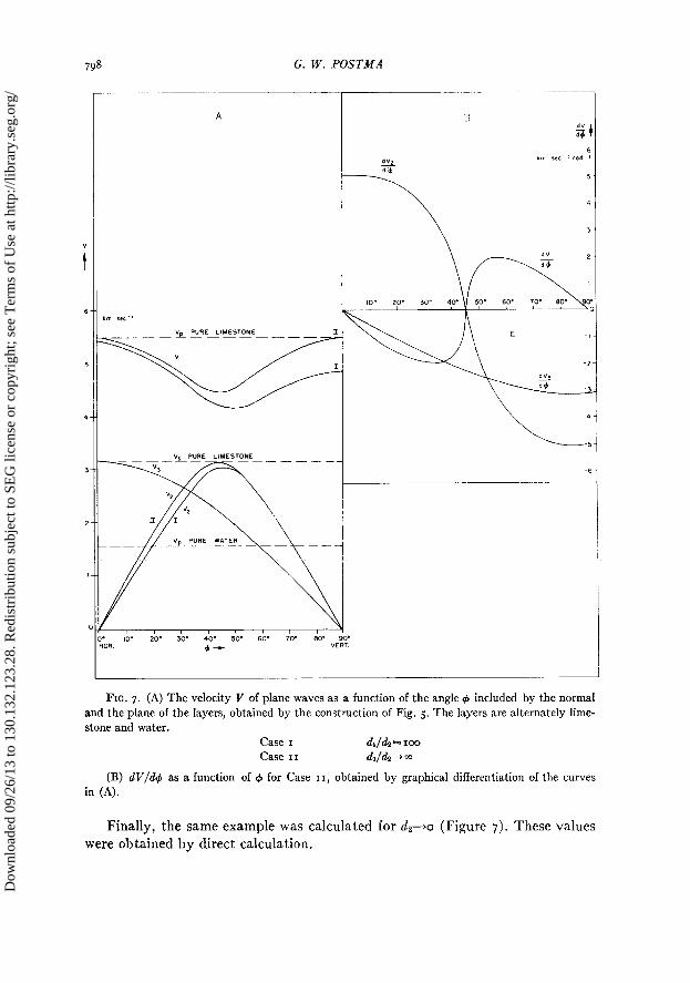
FIG. 7. (A) The velocity V of plane waves as a function of the angle + included by the normal and the plane of the layers, obtained by the construction of Fig. 5. The layers are alternately lime- stone and water.
Case I d,/&= roe Case II &/da+ *
(B) dV/d$ as a function of 9 for Case II, obtained by graphical differentiation of the curves in (A).
Finally, the same example was calculated for a&-+0 (Figure 7). These values were obtained by direct calculation.
Dow
nloa
ded
09/2
6/13
to 1
30.1
32.1
23.2
8. R
edis
trib
utio
n su
bjec
t to
SEG
lice
nse
or c
opyr
ight
; see
Ter
ms
of U
se a
t http
://lib
rary
.seg
.org
/
WAVE PROPAGATION IN ii STRATIFIED MEDIUM 799
We find:
$ VI O0
IO0
5.45
0 5.41 9s
4o”
4.87 5.18
451 4.53 4.47
:zO 4.53 4.87 0 ;:a 5.18
9o” 5.41 5.48
VY Va 0.00 3.16 (km-set-‘) 0.89 3.12 I.75 2.98 2.52 2.74 3.07 2.43 3.16 2.23 3.07 2.03 2.52 I.59 I.75 1.08 0.89 0.53 0.00 0.00
The influence of the vanishing of dz is very noticeable on VI and V, and prac- tically nil on Vs. The assumption that ~44 remains zero when dz+o is rather un- realistic, however, from a physical point of view.
The last examples are rather extreme but they show clearly the type of phenomena we may expect in a layered medium, where one of the constituents has a low resistance against shear.
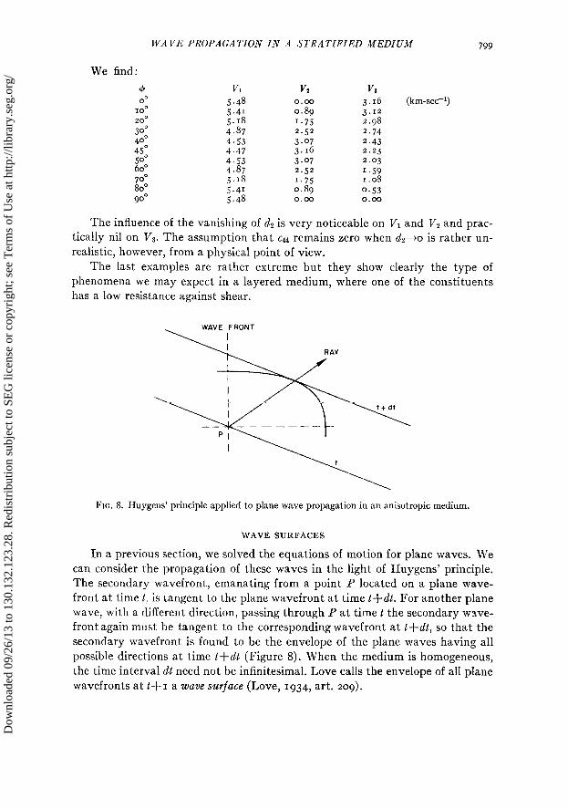
FIG. 8. Huygens’ principle applied to plane wave propagation in an anisotropic medium.
WAVE SURFACES
In a previous section, we solved the equations of motion for plane waves. We can consider the propagation of these waves in the light of Huygens’ principle. The secondary wavefront, emanating from a point P located on a plane wave- front at time t: is tangent to the plane wavefront at time tfdt. For another plane wave, with a different direction, passing through P at time t the secondary wave- front again must be tangent to the corresponding wavefront at t+dt, so that the secondary wavefront is found to be the envelope of the plane waves having all possible directions at time t+dt (Figure 8). When the medium is homogeneous, the time interval dt need not be infinitesimal. Love calls the envelope of all plane wavefronts at t+~ a wave surface (Love, 1934, art. 209).
Dow
nloa
ded
09/2
6/13
to 1
30.1
32.1
23.2
8. R
edis
trib
utio
n su
bjec
t to
SEG
lice
nse
or c
opyr
ight
; see
Ter
ms
of U
se a
t http
://lib
rary
.seg
.org
/
800 G. W. POSTMA
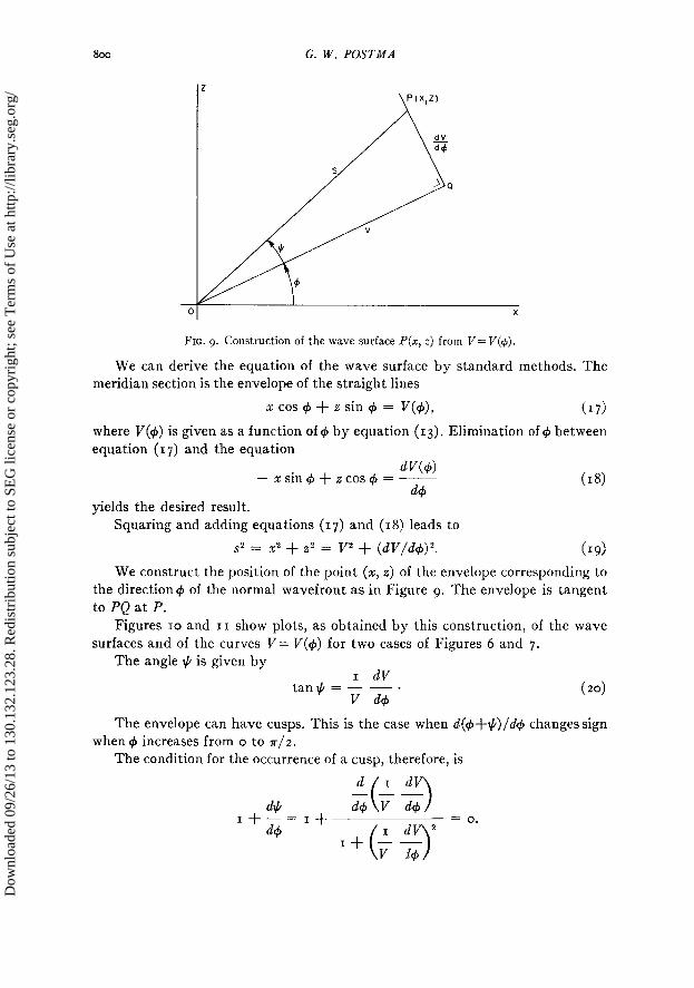
FIG. 9. Construction of the wave surface P(x, z) from V= V(4).
We can derive the equation of the wave surface by standard methods. The meridian section is the envelope of the straight lines
xcos@+zsinf$ = V(4), (17)
where V($J) is given as a function of C#J by equation (13). Elimination of #I between equation (17) and the equation
dV(4) - x sin @J + 2 cos $J = ___
& (18)
yields the desired result. Squaring and adding equations (17) and (IS) leads to
s2 = x2 + 22 = 712 + (m/&)2. (19)
We construct the position of the point (x, z) of the envelope corresponding to the direction4 of the normal wavefront as in Figure 9. The envelope is tangent to PQ at P.
Figures IO and II show plots, as obtained by this construction, of the wave surfaces and of the curves V= V(4) for two cases of Figures 6 and 7.
The angle # is given by I dV
tan+ = - -a v &
(20)
The envelope can have cusps. This is the case when d(4+#)/& changes sign when C#I increases from o to r/2.
The condition for the occurrence of a cusp, therefore, is
d I dV - -__
d# ( ) If-=I+
d+ V d9
d+ 2 =O*
Dow
nloa
ded
09/2
6/13
to 1
30.1
32.1
23.2
8. R
edis
trib
utio
n su
bjec
t to
SEG
lice
nse
or c
opyr
ight
; see
Ter
ms
of U
se a
t http
://lib
rary
.seg
.org
/
WAVE PROPAGATION IN A STRATIFIED MEDIUM 801
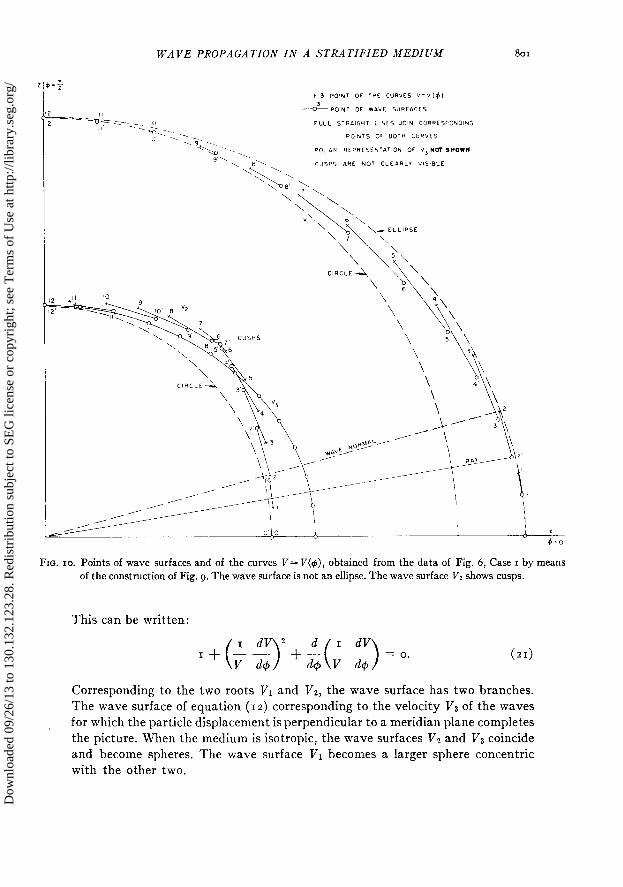
FIG. IO. Points of wave surfaces and of the curves V = V(+), obtained from the data of Fig. 6, Case I by means of the construction of Fig. 9. The wave surface is not an ellipse. The wave surface Vz shows cusps.
This can be written:
Corresponding to the two roots VI and T/Z, the wave surface has two branches. The wave surface of equation (12) corresponding to the velocity Va of the waves
for which the particle displacement is perpendicular to a meridian plane completes
the picture. When the medium is isotropic, the wave surfaces Vz and Vs coincide
and become spheres. The wave surface VI becomes a larger sphere concentric
with the other two.
Dow
nloa
ded
09/2
6/13
to 1
30.1
32.1
23.2
8. R
edis
trib
utio
n su
bjec
t to
SEG
lice
nse
or c
opyr
ight
; see
Ter
ms
of U
se a
t http
://lib
rary
.seg
.org
/
G. W. POSTMA
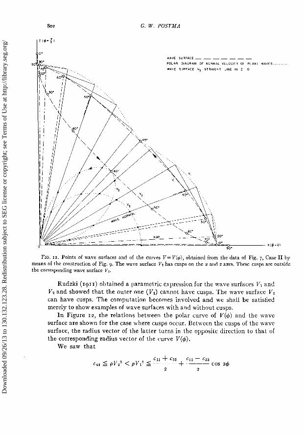
FIG. II. Points of wave surfaces and of the curves V= V(+), obtained from the data of Fig. 7, Case II by means of the construction of Fig. 9. The wave surface V2 has cusps on the x and z axes. These cusps are outside the corresponding wave surface VI.
Rudzki (1911) obtained a parametric expression for the wave surfaces ~~1 and VZ and showed that the outer one (VI) cannot have cusps. The wave surface VZ can have cusps. The computation becomes involved and we shall be satisfied merely to show examples of wave surfaces with and without cusps.
In Figure 12, the relations between the polar curve of V(4) and the wave surface are shown for the case where cusps occur. Between the cusps of the wave surface, the radius vector of the latter turns in the opposite direction to that of the corresponding radius vector of the curve V(4).
We saw that
611 + Cl1 - 633 633 644 5 pvg < pv12 5 p++ cos 24
2 2
Dow
nloa
ded
09/2
6/13
to 1
30.1
32.1
23.2
8. R
edis
trib
utio
n su
bjec
t to
SEG
lice
nse
or c
opyr
ight
; see
Ter
ms
of U
se a
t http
://lib
rary
.seg
.org
/
WAVE PROPAGATION IN A STRATIFIED MEDIUM 803
and that the equality signs are only valid for arbitrary4 when the medium degen- erates into an isotropic medium. If the equality signs had been valid, the wave surface for Vr( = d&/p) would have been an ellipsoid of revolution, and the wave surface Vz a sphere. We therefore conclude that the wave surfaces of Vr and T/‘t are never ellipsoids.
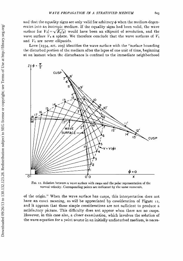
Love (1934, art. 209) identifies the wave surface with the ‘(surface bounding the disturbed portion of the medium after the lapse of one unit of time beginning at an instant when the disturbance is confined to the immediate neighborhood
FIG. 12. Relation between a wave surface with cusps and the polar representation of the normal velocity. Corresponding points are indicated by the same numerals.
of the origin.” When the wave surface has cusps, this interpretation does not have an exact meaning, as will be appreciated by consideration of Figure 12, and it appears that these simple considerations are not sufficient to produce a satisfactory picture. This difficulty does not appear when there are no cusps. However, in this case also, a closer examination, which involves the solution of the wave equation for a point source in an initially undisturbed medium, is neces-
Dow
nloa
ded
09/2
6/13
to 1
30.1
32.1
23.2
8. R
edis
trib
utio
n su
bjec
t to
SEG
lice
nse
or c
opyr
ight
; see
Ter
ms
of U
se a
t http
://lib
rary
.seg
.org
/
804 G. W. POSTMA
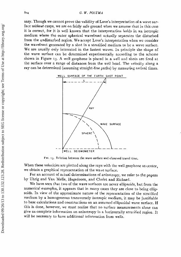
sary. Though we cannot prove the validity of Love’s interpretation of a wave sur- face without cusps, we are on fairly safe ground when we assume that in this case it is correct, for it is well known that the interpretation holds in an isotropic medium where the outer spherical wavefront actually separates the disturbed from the undisturbed region. We accept Love’s interpretation when we consider the wavefront generated by a shot in a stratified medium to be a wave surface. We are usually only interested in the fastest waves. In principle the shape of the wave surface can be determined experimentally according to the scheme shown in Figure 13. A well geophone is placed in a well and shots are fired at the surface over a range of distances from the well head. The velocity along a ray can be determined (assuming straight-line paths) by measuring arrival times.
I WELL SEISMOMETER
FIG. 13. Relation between the wave surface and observed travel time
When- these velocitiesa-re plotted aiong the rays with the well geophone as center, we obtain a graphical representation of the wave surface.
For an account of actual determinations of anisotropy, we refer to the papers by Uhrig and Van Melle, Hagedoorn, and Cholet and Richard.
We have seen that two of the wave surfaces are never ellipsoids, but from the numerical examples, it appears that in many cases they are close to being ellip- soils In view of the approximate nature of the representation of the stratified medium by a homogeneous transversely isotropic medium, it may be justifiable to base calculations and constructions on an assumed ellipsoidal wave surface. If this is done, however, we must realize that no surface measurements alone can give us complete information on anisotropy in a horizontally stratified region. It will be necessary to have additional information from wells.
Dow
nloa
ded
09/2
6/13
to 1
30.1
32.1
23.2
8. R
edis
trib
utio
n su
bjec
t to
SEG
lice
nse
or c
opyr
ight
; see
Ter
ms
of U
se a
t http
://lib
rary
.seg
.org
/
WAVE PROPAGATION IN A STRATIFIED MEDIUM 805
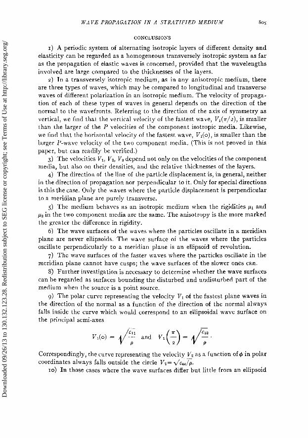
CONCLUSIONS
I) A periodic system of alternating isotropic layers of different density and
elasticity can be regarded as a homogeneous transversely isotropic system as far
as the propagation of elastic waves is concerned, provided that the wavelengths
involved are large compared to the thicknesses of the layers. z) In a transversely isotropic medium, as in any anisotropic medium, there
are three types of waves, which may be compared to longitudinal and transverse
waves of different polarization in an isotropic medium. The velocity of propaga-
tion of each of these types of waves in general depends on the direction of the
normal to the wavefronts. Referring to the direction of the axis of symmetry as
vertical, we find that the vertical velocity of the fastest wave, V1(r/z), is smaller
than the larger of the P velocities of the component isotropic media. Likewise,
we find that the horizontal velocity of the fastest wave, V,(o), is smaller than the
larger P-wave velocity of the two component media. (This is not proved in this
paper, but can readily be verified.)
3) The velocities V1, Vz, VB depend not only on the velocities of the component
media, but also on their densities, and the relative thicknesses of the layers.
4) The direction of the line of the particle displacement is, in general, neither
in the direction of propagation nor perpendicular to it. Only for special directions
is this the case. Only the waves where the particle displacement is perpendicular
to a meridian plane are purely transverse.
5) The medium behaves as an isotropic medium when the rigidities ~1 and
~2 in the two component media are the same. The anisotropy is the more marked
the greater the difference in rigidity.
6) The wave surfaces of the waves where the particles oscillate in a meridian
plane are never ellipsoids. The wave surface of the waves where the particles oscillate perpendicularly to a meridian plane is an ellipsoid of revolution.
7) The wave surfaces of the faster waves where the particles oscillate in the
meridian plane cannot have cusps; the wave surfaces of the slower ones can.
8) Further investigation is necessary to determine whether the wave surfaces
can be regarded as surfaces bounding the disturbed and undisturbed part of the
medium when the source is a point source.
g) The polar curve representing the velocity V1 of the fastest plane waves in
the direction of the normal as a function of the direction of the normal always
falls inside the curve which would correspond to an ellipsoidal wave surface on the principal semi-axes
-
V,(o) = J “” P
and +_)= ,j,/;.
Correspondingly, the curve representing the velocity VP as a function of I#J in polar
coordinates always falls outside the circle V2= d/cJ4/p. IO) In those cases where the wave surfaces differ but little from an ellipsoid
Dow
nloa
ded
09/2
6/13
to 1
30.1
32.1
23.2
8. R
edis
trib
utio
n su
bjec
t to
SEG
lice
nse
or c
opyr
ight
; see
Ter
ms
of U
se a
t http
://lib
rary
.seg
.org
/
806 G. W. POSTMA
it becomes impossible to determine the presence of transverse isotropy from sur- face measurements alone where it is assumed that the layering is horizontal.
II) For the interpretation of refraction work, it can be very important to take anisotropy into account. To a lesser degree, this is true for reflection work.
ACKNOWLEDGMENTS
Of all persons who, in one way or another, contributed to this paper, the author is indebted especially to Dr. P. Hazebroek of the Bataafsche Petroleum Alaat- schappij in the Hague. Dr. Hazebroek’s unpublished work on wave propagation in anisotropic media provided a valuable starting point for the present report.
The author also wishes to express his gratitude to the N. V. de Bataafsche Petroleum Maatschappij and the Shell Development Company for permission to publish this paper.
REFERENCES
Cholet, J. and Richard, H., ‘954, A test on elastic anisotropy measurements at Berriane: Geoph. Prospecting, v. 2, p. 232-246.
Eve, A. S. and Keys, D. A., 1929, Applied geophysics: Cambridge, Cambridge University Press. Hagedoorn, J. G., 1954, A practical example of an anisotropic velocity-layer: Geoph. Prospecting,
v. 2, p. 52-60. Love, A. E. H., 1934, A treatise on the mathematical theory of elasticity: Cambridge, Cambridge
University Press. McCollum, B. and Snell, F. A., 1947, Asymmetry of sound velocity in stratified formations: Early
geophysical papers, Sot. Expl. Geophysicists, p. 216-227. Risnichenko, I. U. V., 1949, Seismic quasi-anisotropy: Akad. Nauk, SSSR. Isw. Ser. Georg. i Geof.,
v. 13, P. 5’8-544. Rudzki, M. P., rgrr, Parametrische Darstelhmg der elastischen Wellen in anisotropen Medien: Bull.
Acad. Cracovie, p. 503. Stoneley, R., ‘949, The seismological implications of aeolotropy in continental structure: Monthly
Notices Royal Astron. Sot., Geoph. Suppl., v. 5, p. 343-353. Thompson, W. T., 1950, Transmission of elastic waves through a stratified solid medium: J. Applied
Physics, v. 21, p. 8993. Uhrig, L. F. and Van Melle, F. A., 1955, Velocity anisotropy in stratified media: Geophysics, v. 20
P. 774-779. White, J. E. and Angona, F. A., r9j5, Elastic wave velocities in laminated media: J. Acoust. Sot.
Am., v. 27. p. 37-3’7.
Dow
nloa
ded
09/2
6/13
to 1
30.1
32.1
23.2
8. R
edis
trib
utio
n su
bjec
t to
SEG
lice
nse
or c
opyr
ight
; see
Ter
ms
of U
se a
t http
://lib
rary
.seg
.org
/