Embed Size (px)
Citation preview

© 2018 IAU, Arak Branch. All rights reserved.
Journal of Solid Mechanics Vol. 10, No. 2 (2018) pp. 232-248
Wave Propagation Analysis of CNT Reinforced Composite Micro-Tube Conveying Viscose Fluid in Visco-Pasternak Foundation Under 2D Multi-Physical Fields
A.H. Ghorbanpour Arani 1, *, M.M. Aghdam
1, M.J. Saeedian
2
1Faculty of Mechanical Engineering, Amirkabir University of Technology, Hafez Avenue, Tehran, Iran
2Faculty of Mechanical Engineering, University of Kashan, Kashan, Iran
Received 19 January 2018; accepted 22 March 2018
ABSTRACT
In this research, wave propagation analysis in polymeric smart nanocomposite
micro-tubes reinforced by single-walled carbon nanotubes (SWCNT)
conveying fluid is studied. The surrounded elastic medium is simulated by
visco-Pasternak model while the composite micro-tube undergoes electro-
magneto-mechanical fields. By means of micromechanics method, the
constitutive structural coefficients of nanocomposite are obtained. The fluid
flow is assumed to be incompressible, viscous and irrotational and the
dynamic modelling of fluid flow and fluid viscosity are calculated using
Navier-Stokes equation. Micro-tube is simulated by Euler-Bernoulli and
Timoshenko beam models. Based on energy method and the Hamilton’s
principle, the equation of motion are derived and modified couple stress theory
is utilized to consider the small scale effect. Results indicate the influences of
various parameters such as the small scale, elastic medium, 2D magnetic field,
velocity and viscosity of fluid and volume fraction of carbon nanotube (CNT).
The result of this study can be useful in micro structure and construction
industries. © 2018 IAU, Arak Branch. All rights reserved.
Keywords: Waves; Beams; Fibre reinforced composites; Piezoelectricity;
Fluid dynamics; Magnetic field.
1 INTRODUCTION
OMPOSITE materials are engineered or naturally occurring materials made from two or more constituent
materials with significantly different physical or chemical properties which remain separate and distinct within
the finished structure. Most composites have strong, stiff fibres in a matrix which is weaker and less stiff. The
objective is usually to make a component which is strong and stiff, often with a low density. Fiber-reinforced
polymer (FRP) is a composite material made of a polymer matrix reinforced with fibers and commonly used in the
aerospace, automotive, marine, and construction industries [1]. Many previous studies with respect to the wave
propagation behavior have been carried out using different models. Dong et al. [2] studied the wave propagation in
multi-walled carbon nanotubes (MWCNTs) embedded in a matrix material. Their results showed that the
surrounding elastic matrix increased the threshold frequency of wave propagation in the MWCNTs. Wang et al [3]
studied the scale effect on wave propagation of double-walled carbon nanotubes (DWCNT). They used Eringen’s
theory and showed the significance of the small-scale effect on wave propagation in MWCNT. Abdollahian et al [4]
______ *Corresponding author. Tel.: +98 31 55912450; Fax: +98 31 55912424.
E-mail address: [email protected] (A.H. Ghorbanpour Arani).
C

233 A.H. Ghorbanpour Arani et al.
© 2018 IAU, Arak Branch
analyzed the non-local wave propagation in embedded armchair triple-walled boron nitride nanotube (TWBNNTs)
conveying viscous fluid using differential quadrature method (DQM). Their results showed that by increasing fluid
velocity, the phase velocity of wave decreases. Kaviani and Mirdamadi [5] investigated the wave propagation
analysis of CNT conveying fluid including slip boundary condition and strain/inertial gradient theory. They showed
that the boundary condition between the interface of fluid and structure, plays an important role on the structural
response. Ghorbanpour Arani et al [6] studied the nonlocal wave propagation in an embedded double –walled
BNNT (DWBNNT) conveying fluid via strain gradient theory. They showed the upstream and downstream wave
propagation. Furthermore, they found that the effect of fluid-conveying on wave propagation of the DWBNNT is
significant at lower wave numbers. Wave propagation in SWCNT under longitudinal magnetic field using nonlocal
Euler–Bernoulli beam theory (EBBT) were analyzed by Narendar et al [7]. Their results showed that the velocity of
flexural waves in SWCNTs increases with the increase of longitudinal magnetic field exerted on it in the frequency
range; 0–20 THz. Ghorbanpour Arani et al [8] studied the nonlocal piezo elasticity based wave propagation of
bonded double-piezoelectric nanobeam-systems (DPNBSs). They obtained phase velocity; cutoff and escape
frequencies of the DPNBSs by an analytical method. Reddy and Arbind [9] presented the bending relationships
between the modified couple stress-based functionally graded Timoshenko beam theory (TBT) and homogeneous
EBBT. They used the modified couple stress for considering the small scale effect. Mosallaie Barzoki et al. [10]
studied the Electro-thermo-mechanical torsional buckling of a piezoelectric polymeric cylindrical shell reinforced by
DWBNNTs with an elastic core. They utilized representative volume element (RVE) based on micromechanical
modeling to determine mechanical, electrical and thermal characteristics of the equivalent composite.
This paper aims to study wave propagation analysis in polymeric smart nanocomposite micro-tubes reinforced
by SWCNT conveying fluid flow. In order to control the stability of the system, composite cylinder is subjected to
an applied electric and magnetic field while the magnetic field is effective in two direction for the first time. The
nanocomposite micro-tube is embedded in a viscoelastic medium which is simulated by visco-pasternak model. The
governing equations are derived using Hamilton’s principle and solved by applying DQM. The influence of fluid
velocity, geometrical parameters of shell, viscoelastic foundation, volume fraction of fiber in polymer matrix, cutoff
and escape frequency on the phase velocity of composite cylindrical shell are investigated.
2 MICRO-ELECTROMECHANICAL MODELS FOR COMPOSITES PROPERTIES
A micro-mechanical models known as "XY PEFRC" or "YX PEFRC" is employed for modeling of coupled
composite micro-structures. A RVE has been considered for predicting the elastic, piezoelectric and dielectric
properties of the smart system. In this research, matrix is assumed to be smart. According to the XY PEFRC micro-
mechanical method, the constitutive equations for the electro-mechanical behavior of the selected RVE are
expressed as [10]:
11 12 131 1 31
12 22 232 2 32
13 23 333 3 33
4423 23 24
5531 31 15
6612 12
0 0 0 0 0
0 0 0 0 0
0 0 0 0 0
0 0 0 0 0 2 0 0
0 0 0 0 0 2 0 0
0 0 0 0 0 2 0 0 0
C C C e
C C C e
C C C e
C e
C e
C
1
2
3
1
2
1 15 11 1
3
2 24 22 2
23
3 31 32 33 33 3
31
12
0 0 0 0 0 0 0
0 0 0 0 0 0 02
0 0 0 0 02
2
E
E
E
D e E
D e E
D e e e E
(1)
In this work, Polyvinylidene fluoride (PVDF) is used as a matrix that reinforced by CNT as a fiber. The
polymeric piezoelectric fiber reinforced composites (PPFRC) is assumed to be orthotropic and homogeneous with

Wave Propagation Analysis of CNT Reinforced Composite …. 234
© 2018 IAU, Arak Branch
respect to their principal axes. Coefficients in the above equation in terms of smart matrix and piezoelectric fibers
properties and volume fraction of the reinforcement are written as follows [11]:
11 11
11
11 111
r m
m r
C CC
C C
121212 11
11 11
1 mr
r m
CCC C
C C
131313 11
11 11
1 mr
r m
CCC C
C C
2 22
12 121222 22 22
11 11 11
11
r m
r m
r m
C CCC C C
C C C
12 1312 13 12 13
23 23 23
11 11 11
11
m mr rr m
r m
C CC C C CC C C
C C C
2 22
13 131333 33 33
11 11 11
11
r m
r m
r m
C CCC C C
C C C
44 44 441r mC C C
66 6655 662
66 66
,(1 )
r m
m r
C CAC C
B A C C C
31 3131 11
11 11
(1 )r m
r m
e ee C
C C
12 13 12 31 12 3132 32 32
11 11 11
(1 )(1 )
r r m mr m
r m
C e C e C ee e e
C C C
13 31 13 31 13 3133 33 33
11 11 11
(1 )(1 )
r r r m mr m
r m
C e C e C ee e e
C C C
24 24 24 15 2(1 ) ,r m B
e e e eB A C
(2)
where
55 55
2 2
55 11 15 55 11 15
(1 )
( ) ( )
p m
p p p m m m
C CA
C e C e
15 15
2 2
55 11 15 55 11 15
(1 )
( ) ( )
p m
p p p m m m
e eB
C e C e
11 11
2 2
55 11 15 55 11 15
(1 )
( ) ( )
p m
p p p m m mC
C e C e
(3)
Superscripts r and m refer to the reinforced and matrix components of the composite, respectively. is also the
volume fraction of the reinforced CNTs in matrix.
3 THE MODIFIED COUPLE STRESS PIEZOELECTRICITY THEORY
Fig. 1 shows a CNT reinforced composite micro-tube embedded in Visco-Pasternak medium. Micro-tube is
conveying fluid and undergoes 2D magnetic and electric field simultaneously.

235 A.H. Ghorbanpour Arani et al.
© 2018 IAU, Arak Branch
(a)
(b)
Fig.1
Schematic of a composite micro-tube embedded in Visco-Pasternak medium conveying fluid subjected to electric and magnetic
field.
Based on the modified couple stress piezoelectricity theory, the strain energy of an elastic beam can be expressed
as [5,9]:
1
2ij ij ij ij i i
VU m D E dV
(4)
where ij are the components of the symmetric part of the Cauchy stress tensor, iD are electric displacement
components, iE axial electric field, ijm denote the components of the deviatoric part of the symmetric couple stress
tensor, and ij are the components of the symmetric curvature tensor which are defined by:
xEx
(5)
2
02ij ijm Gl (6)
, ,
1( )
2ij i j j i
(7)
1
2U
(8)
where 55G C is the shear modulus of elasticity, U is the displacement vector, 0l is a material length scale
parameter and is the rotation vector.
In EBBT displacement fields are expressed as [12]:
,, , ,
, , ,
w x tU x z t u x t z
x
W x z t w x t
(9)
and for TBT [13]:
, , ,
, ,
U x t u x t z x t
W x t w x t
(10)

Wave Propagation Analysis of CNT Reinforced Composite …. 236
© 2018 IAU, Arak Branch
where ( , )U W are the axial and transverse displacements and denotes the rotation of the cross-sectional area of
the beam.
For EBBT Eqs. (6) and (7) are obtained as:
2
2
22 2
55 55 2
1
2
0
2
0
yx xy
xx yy zz xz yz
yx xy o xy o
xx yy zz xz yz
w
x
wm m C l C l
x
m m m m m
2
2
0
xx
xz
U u wz
x x x
U W
z x
(11)
and for TBT Eqs. (6) and (7) are obtained as:
2
2
22 2
55 0 55 0 2
1
4
0
12
2
0
yx xy
xx yy zz xz yz
yx xy xy
xx yy zz xz yz
w
x x
wm m C l C l
x x
m m m m m
xx
xz
U uz
x x x
W U w
x z x
(12)
According to Eq. (1) 1 ,2 ,3y z x , in EBBT 0, 0, 0zx xy yz , stress–strain relation and
electric displacement for piezoelectric materials is given as follows:
33 33
33 33
xx xx x
x xx x
C e E
D e E
(13)
and for TBT 0, 0, 0zx xy yz :
33 33
44
33 33
xx xx x
xz
x xx x
C e E
wC
x
D e E
(14)
By substituting Eqs. (5), (11) and (13) into Eq. (4), the strain energy of micro-tube for EBBT can be obtained as:

237 A.H. Ghorbanpour Arani et al.
© 2018 IAU, Arak Branch
2 2
2 20
12
2
1
2
xx xx xy xy x xV
L
xx xx xy x
U m D E dV
u w wN M P D dx
x xx x
(15)
and by substituting Eqs. (5), (12) and (14) into Eq. (4), the strain energy of micro-tube for TBT can be obtained as:
2
20
12
2
1 1
2 2
xx xx xz xz xy xy x xV
L
xx xx xz xy x
U m D E dV
u w wN M Q P D dx
x x x x xx
(16)
The stress resultants introduced in Eqs. (15) and (16) are defined as:
2, , ,t t t t
xx xx t xx xx t xz xz t xy xy tA A A A
N dA M z dA Q dA P m dA
(17)
and kinetic energy of the micro-tube is:
22
0
, ,1
2 t
L
tube t tA
U x t W x tK dA dx
t t
(18)
where t denote the density of micro-tube.
4 FLUID STRUCTURE INTERACTION
4.1 Navier-Stokes equations
The Navier–Stokes equations describe the motion of viscous fluid substances. It may be used to model the water
flow in a pipe and air flow around a wing. The Navier–Stokes equations in their full and simplified forms help with
the design of aircraft and cars, the study of blood flow and many other things [14].
To evaluate the effect fluid flow on composite micro-tube, Navier–Stokes equation can be used as [15]:
2
f f
dVP V
dt
(19)
where ,f P and f fluid density, static pressure and fluid viscosity, respectively and /d dt can be defined as
follows:
f
du
dt t x
(20)
It is worth mentioning that the left hand of Navier-stokes equation present the kinetic energy of flow fluid. In this
research, it’s considered a Newtonian fluid can be passed through the micro-tube with constant velocity at the first
and end of micro-tube. The fluid flow is assumed to be incompressible, viscous and irrotational. Velocity field
vector ( , )x zV V V for the fluid is the relative velocity including fluid and nanotube velocity. This vector can be
expressed as [16]:
Wave Propagation Analysis of CNT Reinforced Composite …. 238
© 2018 IAU, Arak Branch
,cos
,sin
x f
z f
U x tV u
t
W x tV u
t
(21)
where w
x
and
fu is the fluid velocity.
Using Eq. (21) and (19), it can be expanded in directions ,x z for EBBT as follows:
2 3 2 2 3
2 2 2
22 3 4 2 3
2
2 2 3 2 3
cos sin
sin cos sin
ff f f f f f f f f
f f f f f f f f
u w w uduPz u u u z
x dt x t x tt x t x t
u z u ux x t x t
w
w u w w
x
w
x
(22)
2 2 2 22
2 2
23 2 3
2 2 3
sin cos cos
sin cos
ff f f f f f f f
f f f f f
dw w w wuPu u u
z dt x t x tt
w
x
u ux t x
w w
x
(23)
and for TBT:
2 2 2 2 2
2 2
22 3 3 2 3
2
2 2 2 2 3
cos sin
sin cos sin
ff f f f f f f f f
f f f f f f f f
u w uduPz u u u z
x dt x t x t x tt t
u z u ux x t x t x
w
x
w u w
(24)
2 2 2 22
2 2
23 2 3
2 2 3
sin cos cos
sin cos
f f f f f f f f f
f f f f f
P du t u u u
z dt x t
w w w w
w w
x tt x
u ut x x
w
x
(25)
The virtual work down by fluid can be calculated as follows:
0 f
L
Fluid fA
P PU W dA dx
x z
(26)
4.2 Knudsen number
Knudsen number is a dimensionless parameter defined as the ratio of the mean-free-path of the molecules to a
characteristic length scale which is used for identifying the various flow regimes. For micro and nanotubes, the
radius of the tube is assumed as the characteristic length scale.
According to the Knudsen number the classification of the various flow regimes is given as: continuum flow
regime 2( 10 )Kn , slip flow regime 2 1(10 10 )Kn , transition flow regime 1(10 10)Kn , free molecular
flow regime ( 10)Kn [17]. For BNNT conveying fluid, Kn may be larger than 210 . Therefore, the assumption
of no-slip boundary conditions is no longer credible, and a modified model must be used.

239 A.H. Ghorbanpour Arani et al.
© 2018 IAU, Arak Branch
So ,avg slipV is replaced by ,( )avg no slipVCF V in the basic equations, that VCF is determined as follows[18]:
,
,( )
2(1 ) 1 4
1
avg slip v
avg no slip v
V KnVCF aKn
V Kn
(27)
where v is tangential momentum accommodation coefficient. For most practical applications
v is chosen to be
0.7 and a can be expressed as the following relation:
1
0 1
2tan Ba a a Kn
(28)
In which, 1 4a and 0.04B , are some experimental parameters. The coefficient
0a is formulated as:
0
64lim
43 1
Kn a a
b
(29)
where 1b .
5 VISCO-PASTERNAK FOUNDATION
Based on the Winkler and Visco-Pasternak foundations, the effects of surrounding elastic medium on the nanotubes
are considered as follows [19]:
2
2Elsatic w G
wF K w K
x
(30)
where ElsaticF is the external forces applied on micro-tube. The external work due to surrounding elastic and the
dissipation energy by dampers acting on micro-tube are written as:
0
1
2
L
Elastic ElsaticW F wdx
2
0
1
2
L
damping d
wW C dx
t
(31)
where ,w Gk k and dC is Winkler and Pasternak modulus besides damping coefficient.
6 MAXWELL’S RELATIONS
In this section, the virtual work (effects) of 2D magnetic field (longitudinal and transversal) on microtube due to
CNT fibres has been studied by Maxwell’s relations. Denoting J as current density, h as distributing vector of the
magnetic field, e as strength vectors of the electric field and f as the Lorentz force, the Maxwell relations according
to [20] is given as:

Wave Propagation Analysis of CNT Reinforced Composite …. 240
© 2018 IAU, Arak Branch
0
ˆ ˆ ˆx x x
J h
he
t
h
he H
t
h U H
f f i f j f k J h
(32)
where the Hamilton arithmetic operator is ˆ ˆi kx z
and is the magnetic permeability. The displacement
vector for EBBT is
, ˆ ˆ, ,
w x tU u x t z i w x t j
x
and for TBT is ˆ ˆ( , ) ( , ) ( , )U u x t z x t i w x t j . By
considering 2D magnetic field as a vector ˆ ˆx zH H i H k acting on the CNT fibers, the components of Lorentz
force induced by the 2D magnetic field for EBBT is:
2 3 2
2
2 3 2
2 3 22
2 3 2
0
x z x z
y
z x z x
f H z H Hx x x
f
f H H z Hx x x
u w w
u w w
(33)
and for TBT is:
2 2 2
2
2 2 2
2 2 22
2 2 2
0
x z x z
y
z x z x
f H z H Hx x x
f
f H H z Hx
w
u
x x
u
w
(34)
So the virtual work due to 2D magnetic field is written as:
0 t
L
magnetic x z tA
f U f W dA dx
(35)
7 MOTION EQUATIONS
Using Hamilton’s principle the variational form of the equations of motion can be written as:
1
2
1
1
0
0
( ) 0
0
t
t
elastic Flu
t
t
t
tube ma igne i dt ct
dt
U K dt
K U dt
(36)
For simplification the dimensionless parameters are defined as:

241 A.H. Ghorbanpour Arani et al.
© 2018 IAU, Arak Branch
xX
L
( , )( , )
u wU W
r 33
m
t
CtT
L
L
r
33
33
m
e
LC
33 33
2
11
mC
h
33 44
33 44
33
( , )( , )
m
C CC C
C
33
d
dm
t t
C LC
C A
f
t
AA
A f
f
m
t
t
m
33
f
f fmu u
C
33
f
fm
fL C
2
( , ), f t
t f
t
I II I
A r
2
33
w
w m
t
K LK
A C
33
G
G m
t
KK
A C
33
( , , ) ( , , )x y z x y zmH H H H H H
C
(37)
By setting the coefficients of , ,u w and equal to zero the motion equation can be obtained. It’s also
assumed that is small so cosθ≈ 1 and sinθ≈ θ. the equation of motion for EBBT are obtained as follows:
2 2 2 3 2 2
2
2 2 2
33
2 2 2 2 2
2
22
:1 1
t f zx f f z
ff
A H H A HT T X X T X X
duA C
dT
U W U
U
X
U Uu
(38)
2 2 2 2 4 5
2 2
2 2 2 2 2 4 2 4
3 2 4 4 3
2 2 32 2 2 2 2 3
2
3 4
1 1
1 1 1
:
2 2
t w G d f f z f f f
f f z f f f f
ff
x t
f f
t
Ww K W
W W W W W WI
W U W
K C Au A H ITT X X T X X T
A H H I C I A uX T X X T X X
duA u
W W
AX T dT
W
4 22
2
42
442 2 0 42 2
1 1t xt
W W WI C l
WH
X XX T X
(39)
2 2
2 2:
x
U
x
(40)
and for TBT:
2 2 2 3 2 2
2
2 2 2
33
2 2 2 2 2
2
22
:1 1
t f zx f f z
ff
A H H A HT T X X T X X
duA C
dT
U W U
U
X
U Uu
(41)
2 2 3 3
2 2 2 2 3
2 2 2 2 22 2
2 2 2 2 2
2
44
32
44 42 4 0 44 03
:
1 1
4 4
1
12 2
fw G z f s dx
t
f f
ff f f f f
s
x
WK W K H H A K C C A u
X TX X X T X
du
W U W Ww
W W W W W
WC l
WA A u Au A H
dT X X T X T T X
K CX
C lX
42
4
w
X
(42)

Wave Propagation Analysis of CNT Reinforced Composite …. 242
© 2018 IAU, Arak Branch
3 2 2 22 2
2 2 2 2 2
22
44 44
2 32 2
33 44 0 44 02 32
1
1 1
4 4
: f f f t z s t f s
t
t f
WI H K C I KI I
WI C l C l
X
CXX T X T T
CXX
(43)
2 2
2 2:
x
U
x
(44)
8 SOLUTION METHOD
The wave propagation solution of Eqs. (38) to (44) for simply supported boundary condition can be expressed as
follows:
kX
0
kX
0
kX
0
kX
0
i T
i T
i T
i T
U U e
W W e
e
e
(45)
where 0 0 0 0, , ,U W are the wave amplitude, ( . )k L K is the dimensionless wave number and is the
dimensionless complex frequency of wave motion. By substituting Eq. (49) into Eqs. (38) to (44) for EBBT:
11 12 13 0
21 11 0
31 33 0
0
0 0
0 0
M M M U
M M W
M M
(46)
and for TBT:
011 12 14
021 22 23
032 33
041 44
0 0
0 0
0 0 0
0 0 0
UM M M
WM M M
M M
M M
(47)
where ijM for EBBT are given by:
2 22 2 2 2 2 2 2
33
2 2 3 2 2
12 1
11
13 2, ,
f t f f z
x z x z
M
M
A A k C k H k
M H H k k M H H k
2 2 2 2 4 4
4 2 4 4 2 4
2 2 24 2 2 2 4 2 2 4 3 4
4 4 2 4
33
2
22
4
44 0
2
f f t t t f
d f f f f f f f
t z x g f f f
w t
I k I k A
C A k I k i A k VCFu
I H k H k K k AVCF u k i A VCF u k
K C I
M
C kk l
31 33
2 2,M Mk k
(48)

243 A.H. Ghorbanpour Arani et al.
© 2018 IAU, Arak Branch
where ijM for TBT are given by:
22 2 2 2 2 2 2
33
2 2 2 2 2 2
2 22 2 2 2 2 2 2 3 2 2
44
2 22 2 2 2 2 2 4 2
33 44 44 0
2
11
2
22
2
33
1
2
4
f t f z
f t f f f d
g f s f f x
f f t t f f f t s z t
A A k C k H k
A i A k VCF u A k C
K k A
M
M
M
VCF u k K C k i A VCF u k H k
I I I k C I k C K H I k C l k
4 2
2 2 3 2
14
3 3 3 3
23
12 21
2 23 3
44 44 32
41 4
0 44 44 0
4
2 2
, ,
1 1,
4 4
,
x z x z
s s
M H H k M k M H H k
iK C k CM i l k iK C k C l k
M k M
M i
k
(49)
In order to obtain a non-trivial solution, it is necessary to set the determinant of the coefficient matrix in Eqs.
(46) and (47) equal to zero which yields the algebraic equation. This equation can be solved through a direct
iterative process to evaluate frequency of the micro-tube and consequently phase velocity from /c k .
9 NUMERICAL RESULTS AND DISCUSSION
In this section the result of wave propagation analysis in polymeric smart nanocomposite micro-tubes subjected to
electro-magneto-mechanical fields is studied. The matrix of composite has been mad of PVDF and reinforced by
SWCNT while a Newtonian fluid passes through it with constant velocity. Visco-Pasternak model was also selected
to simulate the surrounded elastic medium. The results presented here are based on Table 1., that used for geometry
and material properties of PVDF and CNT [21]. It’s assumed that the water passes through the micro-composite
with: 31000 ,f Kg m 3 20.653 10 . ,N s m 0.02Kn and 0.05fu .
Table 1
Material properties of PVDF and CNT [21].
33 0 33e 44C 33C
0.1 20 C m 1191.5 Gpa 1444.2 Gpa 31400 Kg m CNT
12.5 20.13 C m 215 Gpa 238.24 Gpa 31780 Kg m PVDF
12
0 8.854185 10 F m
The numerical values of other parameters have been considered as follows:
0.6, 80, 5, 0, 0.3, 0.2, 0.01, 1, 0.34( ), 3.4( )s x y z r w G d ik H H H K K C h m r m
In this section, effects of dimensionless parameters such as Winkler and Visco-Pasternak modules, Knudsen
number ( Kn ), cutoff and escape frequency, fluid viscosity and length scale on the dimensionless phase velocity and
fluid velocity of two simply supported composite cylinder are shown in Figs. 2 to 9.
Figs. 2(a) and 2(b) shows the effect of viscoelastic medium on dimensionless phase velocity versus
dimensionless wave number for EBBT and TBT. Three type of elastic medium have been considered in this research
including: Winkler, Pasternak and Visco-Pasternak foundation. Visco-Pasternak foundation introduces the damping
coefficient cd in spite of normal wK and shear modulus gK . As can be seen from the Figs. 2)a) and 2)b), normal
and shear modulus in Winkler and Pasternak models play a positive role to stability of system while damping effect
lead to instability. On the other hand, in large dimensionless wave number, the difference among three models
becomes more visible.

Wave Propagation Analysis of CNT Reinforced Composite …. 244
© 2018 IAU, Arak Branch
1 2 3 4 5 6 70
0.1
0.2
0.3
0.4
0.5
0.6
0.7
Dimensionless wave number (K)
Dim
en
sio
nle
ss p
hase
velo
cit
y (
/k
)
Kw=0.6
Kw=0.6,Kg=0.015
Kw=0.6,Kg=0.015,Cd=1
1.04 1.06 1.08 1.1 1.12
0.324
0.326
0.328
0.33
0.332
0.334
6.6 6.7 6.8 6.9 7
0.01
0.02
0.03
0.04
EBBT
(a)
1 2 3 4 5 6 70
0.1
0.2
0.3
0.4
0.5
0.6
0.7
Dimensionless wave number (K)
Dim
en
sio
nle
ss p
hase
velo
cit
y (
/k
)
Kw=0.6
Kw=0.6,Kg=0.015
Kw=0.6,Kg=0.015,Cd=1
1.06 1.08 1.1 1.12 1.14
0.302
0.304
0.306
0.308
0.31
6.5 6.6 6.7 6.8
0
0.02
0.04
TBT
(b)
Fig.2
a) Effect of viscoelastic medium on dimensionless phase velocity versus dimensionless wave number for EBBT. b) Effect of
viscoelastic medium on dimensionless phase velocity versus dimensionless wave number for TBT.
To show the effect of fluid density and viscosity on the dimensionless phase velocity, Fig. 3 was drawn for TBT.
Since it’s not possible to investigate the viscosity in a special numerical rang, we considered three Newtonian fluid
with specific feature that used in many fluid structure interaction such as Aston, Water and Blood (Blood is
considered Newtonian fluid in some conditions). It’s clear from the figure that the changes in the results are
negligible so that it can be ignored.
1 2 3 4 5 6 70
0.05
0.1
0.15
0.2
0.25
0.3
0.35
0.4
Dimentionless Wave number (k)
Dim
enti
on
less
ph
ase
vel
oci
ty (
/k
)
3 3.50.02
0.025
0.03
0.035
0.04
Aston,f=791
Water,f=1000
Blood,f=1060
TBT
Fig.3
Effect of fluid density and viscosity on the dimensionless
phase velocity for TBT.
The characteristics of elastic wave propagation for a given wave number investigate in two different waves,
propagating in two opposite directions of upstream and downstream. The corresponding wave frequencies are called
upstream and downstream frequencies [22]. According to Ref. [5] the numerical results demonstrate that these
frequencies have different values when there is a fluid flowing through a tube with an infinite length. These wave
frequencies are the same when there is either no flow or the flow is still [23]. Also in Ref. [5], the difference
between upstream and downstream have been clearly stated.
Figs. 4(a) and 4(b) shows variation of dimensionless phase velocity versus dimensionless wave number for
EBBT and TBT in different length scale parameters. As can be seen from the figure with increasing length scale
parameters in modified couple stress theory the dimensionless phase velocity shift up. Comparison between the Figs.
4(a) and 4(b) shows that the dimensionless phase velocity in EBBT is more than TBT. For both beam models, two
phase velocity curves of upstream and downstream waves join at higher wave numbers that indicate the fluid flow
has no effect in the wave propagation of the higher wave numbers. The dimensionless phase velocity decreases and
become zero at dimensionless wave number, indicating the critical fluid velocity is reached and the tube losses its
stability.
Figs. 5(a) and 5(b) shows the variation of dimensionless phase velocity versus dimensionless wave number for
EBBT and TBT in different volume fraction of CNT. It is evident when the volume fraction of fibers increases the
composite becomes stronger so the dimensionless phase velocity grows to higher values.

245 A.H. Ghorbanpour Arani et al.
© 2018 IAU, Arak Branch
0 0.01 0.02 0.03 0.04 0.050
0.01
0.02
0.03
0.04
0.05
0.06
0.07
0.08
Dimentionless fluid velocity (uf
*)
Dim
enti
on
less
ph
ase
vel
oci
ty (
/k
)
l0
*=0
l0
*=0.02
l0
*=0.04
Upstream
Downstream
EBBT
(a)
0 0.01 0.02 0.03 0.04 0.050
0.01
0.02
0.03
0.04
0.05
0.06
0.07
0.08
Dim
enti
on
less
ph
ase
vel
oci
ty (
/k
)
Dimentionless fluid velocity (uf
*)
l0
*=0
l0
*=0.02
l0
*=0.04
TBT
Downstream
Upstream
(b)
Fig.4
a) Variation of dimensionless phase velocity versus dimensionless wave number for EBBT in different length scale parameters.
b) Variation of dimensionless phase velocity versus dimensionless wave number for TBT in different length scale parameters.
0 0.01 0.02 0.03 0.04 0.050
0.01
0.02
0.03
0.04
0.05
0.06
0.07
0.08
Dim
enti
on
less
ph
ase
vel
oci
ty (
/k
)
Dimentionless fluid velocity (uf
*)
=0
=0.1
=0.2
EBBT
Upstream
Downstream
(a)
0 0.01 0.02 0.03 0.04 0.050
0.01
0.02
0.03
0.04
0.05
0.06
0.07
0.08
Dimentionless fluid velocity (uf
*)
Dim
enti
on
less
ph
ase
vel
oci
ty (
/k
)
=0
=0.1
=0.2
TBT
Upstream
Downstream
(b)
Fig.5
a) Variation of dimensionless phase velocity versus dimensionless wave number for EBBT in different volume fraction of CNT.
b) Variation of dimensionless phase velocity versus dimensionless wave number for TBT in different volume fraction of CNT.
In physics, a cutoff frequency is a boundary in a system's frequency response at which energy flowing through
the system begins to be reduced rather than passing through. In the case of a waveguide, the cutoff frequencies
correspond to the lower and upper cutoff wavelengths. The cutoff frequency of a waveguide is the lowest frequency
for which a mode will propagate in it.
Cutoff frequency is obtained by setting the longitudinal wave number equal to zero and solving for the
frequency. Any exciting frequency lower than the cutoff frequency will attenuate, rather than propagate.
Fig. 6 displays the variation of dimensionless cutoff frequency in a limited interval of dimensionless fluid
velocity. It’s found from the figure that the cutoff frequency decreases linearly and sharply with increasing the
dimensionless fluid velocity but the slop of changes in EBBT is lower than TBT, while the first value of cutoff
frequency in 0fu is the same for both theories.
0 0.01 0.02 0.03 0.04 0.050.17
0.175
0.18
0.185
0.19
Dimentionless fluid velocity (uf
*)
Dim
enti
on
less
cu
t-o
ff f
req
uen
cy
EBBT
TBT
Fig.6
Variation of dimensionless cutoff frequency versus dimensionless
fluid velocity.
Wave Propagation Analysis of CNT Reinforced Composite …. 246
© 2018 IAU, Arak Branch
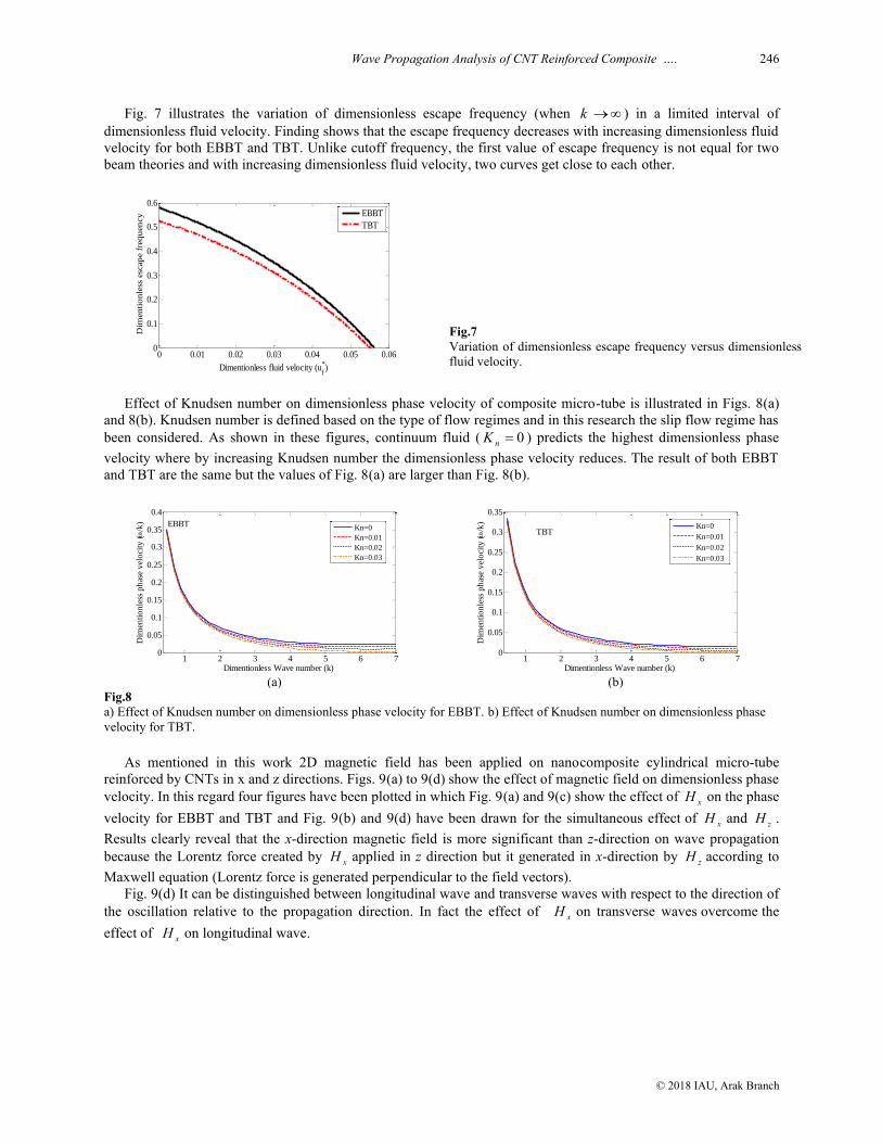
Fig. 7 illustrates the variation of dimensionless escape frequency (when k ) in a limited interval of
dimensionless fluid velocity. Finding shows that the escape frequency decreases with increasing dimensionless fluid
velocity for both EBBT and TBT. Unlike cutoff frequency, the first value of escape frequency is not equal for two
beam theories and with increasing dimensionless fluid velocity, two curves get close to each other.
0 0.01 0.02 0.03 0.04 0.05 0.060
0.1
0.2
0.3
0.4
0.5
0.6
Dimentionless fluid velocity (uf
*)
Dim
en
tio
nle
ss e
scap
e f
req
uen
cy
EBBT
TBT
Fig.7
Variation of dimensionless escape frequency versus dimensionless
fluid velocity.
Effect of Knudsen number on dimensionless phase velocity of composite micro-tube is illustrated in Figs. 8(a)
and 8(b). Knudsen number is defined based on the type of flow regimes and in this research the slip flow regime has
been considered. As shown in these figures, continuum fluid ( 0nK ) predicts the highest dimensionless phase
velocity where by increasing Knudsen number the dimensionless phase velocity reduces. The result of both EBBT
and TBT are the same but the values of Fig. 8(a) are larger than Fig. 8(b).
1 2 3 4 5 6 70
0.05
0.1
0.15
0.2
0.25
0.3
0.35
0.4
Dim
enti
on
less
ph
ase
vel
oci
ty (
/k
)
Dimentionless Wave number (k)
Kn=0
Kn=0.01
Kn=0.02
Kn=0.03
EBBT
(a)
1 2 3 4 5 6 70
0.05
0.1
0.15
0.2
0.25
0.3
0.35
Dim
enti
on
less
ph
ase
vel
oci
ty (
/k
)
Dimentionless Wave number (k)
Kn=0
Kn=0.01
Kn=0.02
Kn=0.03
TBT
(b)
Fig.8
a) Effect of Knudsen number on dimensionless phase velocity for EBBT. b) Effect of Knudsen number on dimensionless phase
velocity for TBT.
As mentioned in this work 2D magnetic field has been applied on nanocomposite cylindrical micro-tube
reinforced by CNTs in x and z directions. Figs. 9(a) to 9(d) show the effect of magnetic field on dimensionless phase
velocity. In this regard four figures have been plotted in which Fig. 9(a) and 9(c) show the effect of xH on the phase
velocity for EBBT and TBT and Fig. 9(b) and 9(d) have been drawn for the simultaneous effect of xH and
zH .
Results clearly reveal that the x-direction magnetic field is more significant than z-direction on wave propagation
because the Lorentz force created by xH applied in z direction but it generated in x-direction by zH according to
Maxwell equation (Lorentz force is generated perpendicular to the field vectors).
Fig. 9(d) It can be distinguished between longitudinal wave and transverse waves with respect to the direction of
the oscillation relative to the propagation direction. In fact the effect of xH on transverse waves overcome the
effect of xH on longitudinal wave.

247 A.H. Ghorbanpour Arani et al.
© 2018 IAU, Arak Branch
1 2 3 4 5 6 70
0.05
0.1
0.15
0.2
0.25
0.3
0.35
Dim
en
tio
nle
ss p
hase
velo
cit
y (
/k
)
Dimentionless Wave number (k)
Hx
*=0
Hx
*=10
Hx
*=20
Hx
*=30
EBBT
(a)
1 2 3 4 5 6 70
0.05
0.1
0.15
0.2
0.25
0.3
0.35
Dimentionless Wave number (k)
Dim
en
tio
nle
ss p
hase
velo
cit
y (
/k
)
Hx
*=0
Hx
*=10
Hx
*=20
Hx
*=30
TBT
(b)
1 2 3 4 5 6 70
0.05
0.1
0.15
0.2
0.25
0.3
0.35
Dimentionless Wave number (k)
Dim
enti
on
less
ph
ase
vel
oci
ty (
/k
)
5.29 5.3 5.31
0.0115
0.0115
0.0115
0.0116
0.0116
Hx
*=5,H
z
*=0
Hx
*=5,H
z
*=10
Hx
*=5,H
z
*=20
Hx
*=5,H
z
*=30
EBBT
(c)
1 2 3 4 5 6 70
0.05
0.1
0.15
0.2
0.25
0.3
0.35
Dim
en
tio
nle
ss p
hase
velo
cit
y (
/k
)
Dimentionless Wave number (k)
Hx
*=5,H
z
*=0
Hx
*=5,H
z
*=10
Hx
*=5,H
z
*=20
Hx
*=5,H
z
*=30
5.29 5.3 5.31
7.38
7.4
7.42
x 10-3
TBT
(d)
Fig.9
a) Effect of magnetic field (xH ) on dimensionless phase velocity for EBBT. b) Effect of magnetic field (
xH ) on dimensionless
phase velocity for TBT. c) Effect of 2D magnetic field ( ,x zH H ) on dimensionless phase velocity for EBBT. d) Effect of 2D
magnetic field ( ,x zH H ) on dimensionless phase velocity for TBT.
10 CONCLUSIONS
Wave propagation analysis in smart polymeric nanocomposite micro-tubes reinforced by SWCNT conveying fluid
was studied in this research. Visco-Pasternak foundation was utilized for modelling of elastic medium while the
composite micro-tube subjected to electro-magneto-mechanical fields. The constitutive structural coefficients of
nanocomposite were obtained by means of micromechanics method. The fluid flow was assumed to be
incompressible, viscous and irrotational to use of Navier-Stokes equation. Micro-tube was simulated by both
Euler-Bernoulli and Timoshenko beam models. Results indicated the influences of various parameters that have
been listed as follows:
Normal and shear modulus in Winkler and Pasternak models play a positive role to stability of system
while damping effect lead to instability.
The changes in the results due to change in type of fluid (density and viscosity) is negligible so that it can
be ignored.
Increasing length scale parameters in modified couple stress theory, the dimensionless phase velocity shift
up. Comparison between the results show that the dimensionless phase velocity in EBBT is more than TBT.
For both EBBT and TBT models, upstream and downstream waves join at higher wave numbers that
indicate the fluid flow has no effect in the wave propagation of the higher wave number.
When the volume fraction of fibers increase the composite become stronger, so the dimensionless phase
velocity grows to higher values.
Cutoff frequency decrease linearly and sharply with increasing dimensionless fluid velocity but the slop of
changes in EBBT is lower than TBT while the first value of cutoff frequency in 0fu is the same for both
theories.

Wave Propagation Analysis of CNT Reinforced Composite …. 248
© 2018 IAU, Arak Branch
Escape frequency decrease with increasing dimensionless fluid velocity for both EBBT and TBT where the
numerical values of both models get close to each other in high fluid velocity.
This study gives physical insights which may be useful for the design and wave propagation analysis of MEMS.
ACKNOWLEDGMENTS
The author would like to thank the reviewers for their comments and suggestions to improve the clarity of this
article.
REFERENCES
[1] Masuelli M.A., 2013, Fiber Reinforced Polymers,The Technology Applied for Concrete Repair, Argentina.
[2] Dong K., Zhu S.Q., Wang, X., 2006, Wave propagation in multiwall carbon nanotubes embedded in a matrix material,
Composite Structures 43(1): 194-202.
[3] Wang Q., Zhou G.Y., Lin K.C., 2006, Scale effect on wave propagation of double-walled carbon nanotubes,
International Journal of Solids and Structures 43(20): 6071-6084.
[4] Abdollahian M., Ghorbanpour Arani A., Mosallaie Barzoki A.A., Kolahchi R., Loghman A., 2013, Non-local wave
propagation in embedded armchair TWBNNTs conveying viscous fluid using DQM, Physica B 418: 1-15.
[5] Kaviani F., Mirdamadi H.Z., 2013, Wave propagation analysis of carbon nano-tube conveying fluid including slip
boundary condition and strain/inertial gradient theory, Computers and Structures 116: 75-87.
[6] Ghorbanpour Arani A., Kolahchi R., Vossough H., 2012, Nonlocal wave propagation in an embedded DWBNNT
conveying fluid via strain gradient theory, Physica B 407(21): 4281-4286.
[7] Narendar S., Gupta S.S., Gopalakrishnan S., 2012, Wave propagation in single-walled carbon nanotube under
longitudinal magnetic field using nonlocal Euler–Bernoulli beam theory, Applied Mathematical Modelling 36(9): 4529-
4538.
[8] Ghorbanpour Arani A., Kolahchi R., Mortazavi S.A., 2014, Nonlocal piezoelasticity based wave propagation of bonded
double-piezoelectric nanobeam-systems, International Journal of Mechanics and Materials 10(2): 179-191.
[9] Reddy J.N., Arbind A., 2012, Bending relationships between the modified couple stress-based functionally graded
Timoshenko beams and homogeneous Bernoulli–Euler beams, Annals of Solid and Structural Mechanics 3(1-2):15-26.
[10] Mosallaie Barzoki A.A., Ghorbanpour Arani A., Kolahchi R., Mozdianfard M.R., Loghman A., 2013, Nonlinear
buckling response of embedded piezoelectric cylindrical shell reinforced with BNNT under electro–thermo-mechanical
loadings using HDQM, Composites Part B: Engineering 44(1): 722-727.
[11] Tan P., Tong L., 2001, Micro-electromechanics models for piezoelectric-fiber-reinforced composite materials,
Composites Science and Technology 61(5): 759-769.
[12] Kuang Y.D., He X.Q., Chen C.Y., Li G.Q., 2009, Analysis of nonlinear vibrations of double walled carbon nanotubes
conveying fluid, Computational Materials Science 45(4): 875-580.
[13] Reddy J.N., 2002, Energy Principles and Variational Methods in Applied Mechanics, John Wiley, New York.
[14] Acheson D.J., 1990, Elementary Fluid Dynamics, Oxford Applied Mathematics and Computing Science Series, Oxford
University Press.
[15] Fox R.W., McDonald A.T., Pritchard P.J., 2004, Introduction to Fluid Mechanics, Elsevier Ltd.
[16] Paidoussis, M.P., 1998, Fluid-Structure Interactions, Academic Press, California, USA.
[17] Karniadakis G., Eskok A.B., Aluru N., 2005, Microflows and Nanoflows: Fundamentals and Simulation, Springer.
[18] Mirramezani M., Mirdamadi H.R., 2012, The effects of Knudsen-dependent flow velocity on vibrations of a nano-pipe
conveying fluid, Archive of Applied Mechanics 82(7): 879-890.
[19] Ghorbanpour Arani A., Amir S., 2013, Electro-thermal vibration of visco-elastically coupled BNNT systems conveying
fluid embedded on elastic foundation via strain gradient theory, Physica B 419: 1-6.
[20] Kraus J., 1984, Electromagnetics, McGrawHill, USA.
[21] Cheng Z.Q. Lim C.W., Kitipornchai S., 2000, Three-dimensional asymptotic approach to inhomogeneous and
laminated piezoelectric plates, International Journal of Solids and Structures 37(23): 3153-3175.
[22] Zhang X.M., 2002, Parametric studies of coupled vibration of cylindrical pipes conveying fluid with the wave
propagation approach, Composite Structures 80(3-4): 287-295.
[23] Wang L., 2010, Wave propagation of fluid-conveying single-walled carbon nanotubes via gradient elasticity theory,
Computational Materials Science 49(4): 761-766.


![Buckling Behavior of 3D Randomly Oriented CNT Reinforced … · 2015. 12. 4. · reinforced composites [2] ... Increased use of nanocomposite in various structural applications necessitates](https://img.pdfslide.us/doc/110x75/5ff8f1917772ef0e55181237/buckling-behavior-of-3d-randomly-oriented-cnt-reinforced-2015-12-4-reinforced.jpg)