Embed Size (px)
Citation preview

Acta MechDOI 10.1007/s00707-016-1781-4
ORIGINAL PAPER
Y. Kiani
Buckling of FG-CNT-reinforced composite plates subjectedto parabolic loading
Received: 6 August 2016© Springer-Verlag Wien 2016
Abstract It is known that the distribution of stresses in a rectangular plate is the same as the applied stresseson the boundaries when the loading is uniform or linearly varying. For other types of compressive loads, forinstance parabolic compressive loading, the distribution of stresses in the plate is different from the appliedloads at the boundaries of the plate. For such conditions, to obtain the buckling loads of the plate, an accurateprebuckling analysis should be performed. The present research aims to obtain the buckling loads and bucklingpattern of composite plates reinforced with carbon nanotubes with uniform or functionally graded distributionacross the plate thickness. The properties of the composite media are obtained based on a modified rule ofmixtures approach with the introduction of efficiency parameters. First-order shear deformation plate theoryis used to approximate the plate kinematics. The plate is subjected to uniaxial compressive loads which varyas parabolic functions across the width of the plate. At first, using the Ritz method and Airy stress functionformulation, the distribution of stress resultants in the plate domain is obtained as a two-dimensional elasticityformulation. Afterwards, by means of the Chebyshev polynomials as the basic functions of the Ritz solutionmethod, an eigenvalue problem is established to obtain the buckling load and buckling shape of the plate.Comparison studies are provided to assure the accuracy of the presented formulation for isotropic homogeneousand cross-ply laminated plates. Afterwards, parametric studies are performed for composite plates reinforcedwith carbon nanotubes.
1 Introduction
Rectangular plates are a part of more complex structures, and due to the loading condition of the structure, theapplied load on the rectangular platemay not be uniform. Nonuniform distribution of in-plane loads is observedin the case of an I beam or wide-flanged beam subjected to a bending moment at the ends or lateral loads onthe flange, aircraft wings, stiffened plates in the ship structures, and multi-storey buildings by the adjoiningstructures. For nonuniform distribution of compressive in-plane loads acting on the plate edges, understandingthe buckling behaviour becomes important and should be studied to grasp the general information on theresponse of the structure which leads to a reliable design.
A literature survey reveals that the linear buckling problem of rectangular plates subjected to uniformcompression is well documented in the open literature. In this type of loading, the differential equationsassociated with the onset of buckling are linear with constant coefficients. Furthermore, the distribution of in-plane stresses within the plate is similar to the applied edge loads. In comparison with uniform edge loading,less researches are available on the buckling behaviour of rectangular plates subjected to nonuniform edgeloadings. The reason is that the governing equations for such problems have nonconstant coefficients. Amongthe buckling problems with nonuniform edge loading, linearly varying loads are more observed since in this
Y. Kiani (B)Faculty of Engineering, Shahrekord University, Shahrekord, IranE-mail: [email protected]; [email protected]

Y. Kiani
case the prebuckling loads are the same as the applied in-plane loads. For other types of nonuniform loading,the distribution of in-plane stresses in the plate is different from the applied in-plane loads, and to obtain thecritical buckling loads of the plate, prebuckling loads should be obtained accurately. This is the reason of thelimited number of investigations dealing with the buckling of rectangular plates with nonuniform compression.
Based on a mesh-free formulation, Chen and Liew [1] obtained the critical buckling loads of homoge-neous and functionally graded material plates subjected to point force, partial compression, and parabolicloading. This research is based on the first-order plate theory and a mesh-free method based on the radialbasis functions. Based on a two-dimensional generalised differential quadrature, Wang et al. [2] obtainedthe buckling loads of thin rectangular plates based on the classical plate theory. In this research, the plate issubjected to uniaxial parabolic in-plane loads. Prior to the eigenvalue analysis to obtain the buckling loadsof the plate, a two-dimensional elasticity problem is solved to extract the distribution of in-plane stressesinduced by the nonuniform compression. Tang and Wang [3] reported the buckling loads of symmetricallylaminated rectangular plates subjected to parabolic loading. A Ritz formulation with the aid of Airy stressfunction formulation is developed to obtain the distribution of normal and shear stresses within the plate.Afterwards, the buckling problem of the plate is formulated using the two-dimensional generalised differentialquadrature method suitable for arbitrary combinations of clamped and simply supported boundary conditions.Panda and Ramachandra [4] developed, respectively, a Ritz and a Galerkin procedure to obtain the prebuck-ling and buckling stresses of the isotropic homogeneous and cross-ply laminated plates. In the prebucklingstate, a three-parameter stress function comprising polynomial functions satisfying all of the force boundaryconditions on the edges of the plate is constructed. The unknown parameters are obtained via the minimumpotential energy criterion. The obtained prebuckling forces are inserted into the stability equations of a thickplate whose solution is estimated by means of the beam function. The developed solution, also, may be usedfor arbitrary combinations of clamped and simply supported boundary conditions. Ramachandra and Panda[5] developed their previous investigation [4] to analyse the dynamic stability of rectangular plates loaded by aparabolically varying load. Similar to the previous investigation of the authors [4], Ritz and Galerkin methodsare used, to obtain the distribution of in-plane forces and instability regions, respectively. Ovesy and Fazilati[6] developed a finite strip method to distinguish the instability regions of a cylindrical shell panel subjectedto compressive loads which vary as a parabolic function of the panel width. Dey et al. [7] obtained the linearbuckling loads and also the postbuckling equilibrium path of rectangular sandwich plates subjected to eitherpartial or parabolic loading. In this research, each of the layers has its own kinematics, and the continuity of thedisplacements between the layers is satisfied. In this analysis, Dey et al. [7] extended the previous formulationof [4,5] suitable for not only the parabolic but also the partial loading. Panda and Ramachandra [8] obtainedthe prebuckling, buckling and postbuckling responses of rectangular cross-ply laminated plates subjected touniaxial compression. Panda and Ramachandra [9] presented a solution based on the Galerkin method suitablefor a postbuckling analysis of cylindrical panels with all edges simply supported and subjected to uniaxial orbiaxial parabolic loading. To trace the equilibrium path, the Newton–Raphson method in conjunction with theRiks procedure is implemented.
Carbon nanotubes (CNTs) have exceptional thermomechanical properties which makes them a candidatefor the reinforcement of composites [10]. It is reported that nonuniform distribution of CNTs may be achievedby a powder metallurgy process [11]. Therefore, the concept of FGMs and CNTs may be achieved togethervia a nonuniform distribution of CNTs through a specific direction [12]. This class of materials is known asfunctionally graded carbon nanotube-reinforced composites (FG-CNTRC).
With the introduction of FG-CNTRC materials, many researches are devoted to the stability analysis ofFG-CNTRC structures. Among the reported works on stability of FG-CNTRC plates, one may refer to thestability analysis of skew plates made of FG-CNTRC based on a first-order plate theory and an element-freeformulation carried out by Zhang et al. [13] an investigation of Lei et al. [14] for a stability analysis of FG-CNTRC rectangular plates based on the element-free kp-Ritz method, a buckling analysis of Malekzadehand Shojaee [15] for laminated plates in a arbitrary quadrilateral shape made from FG-CNTRC layers usinga generalised differential quadrature, the development of an element-free method for a buckling analysis ofskew-shaped FG-CNTRC plates resting on a two-parameter elastic foundation performed by Lei et al. [16],and the buckling and postbuckling of FG-CNTRC plates [17] and sandwich plates with FG-CNTRC facesheets [18] with simply supported edges based on a two-step perturbation technique. However, in all of thesementioned works, the in-plane applied loads are of uniform type.
The aim beyond the present research is to extend the available works on the stability analysis of FG-CNTRC plates. Buckling load factors are obtained for a rectangular shape composite plate reinforced withsingle-walled carbon nanotubes. At first, a prebuckling analysis is performed to obtain the accurate distribution

Buckling of FG-CNT-reinforced composite plates
of in-plane loads due to the applied parabolic compression. Afterwards, stability equations are discretized withthe aid of the Ritz method where the shape functions are constructed in terms of the Chebyshev polynomials.The resulting eigenvalue problem is established and solved for various combinations of boundary conditions,aspect ratio, side-to-thickness ratio, CNT volume fraction, and CNT dispersion profile. It is shown that thebuckling loads of the plate are affected by the CNT characteristics significantly.
2 Basic formulation
An FG-CNTRC rectangular plate is considered is this research. Thickness, width and length of the plate aredenoted by, h, b, and a, respectively. The conventional Cartesian coordinate system with its origin locatedat the centre of the plate where −0.5a ≤ x ≤ +0.5a, −0.5b ≤ y ≤ +0.5b, and −0.5h ≤ z ≤ +0.5h isconsidered. The geometric characteristics of the plate, applied coordinate system, and applied compressiveloads are depicted in Fig. 1.
The plate is made from a polymeric matrix reinforced with single-walled carbon nanotubes (SWCNT). Thedistribution of SWCNT across the plate thickness may be uniform (referred to as UD) or functionally graded(referred to as FG). In this research, two types of mid-plane symmetric FG distribution of CNTs and the UDcase are considered. FG-O and FG-X CNTRC are the functionally graded distribution of carbon nanotubesacross the thickness direction of the rectangular composite plate.
Generally, the effective mechanical properties of the FG-CNTRC rectangular plate are obtained using thewell-known homogenisation schemes, such as Mori-Tanaka scheme [19] or the rule of mixtures [20]. For thesake of simplicity, in the present research, the rule of mixtures is used to obtain the properties of the compositeplate. However, to account for the scale-dependent properties of nanocomposite media, efficiency parametersare introduced. The refined rule of mixture approach which contains the efficiency parameters has been usedextensively in analysis of FG-CNTRC beams [21–24], plates [25–27], panels [28–30], and shells [31–33].According to the rule, the effective material properties may be written as [12,34]
E11 = η1VCN ECN11 + VmE
m,
η2
E22= VCN
ECN22
+ VmEm
,
η3
G12= VCN
GCN12
+ VmGm
. (1)
In the above equations, η1, η2, and η3 are the so-called efficiency parameters which as mentioned earlierare introduced to account for the size-dependent material properties of the plate. These constants are chosen toequal the obtained values of Young’s modulus and shear modulus from the present modified rule of mixtureswith the results obtained according to themolecular dynamics simulations [34]. Besides, ECN
11 , ECN22 , andGCN
12are the elasticity modulus and shear modulus of SWCNTs, respectively. Furthermore, Em and Gm indicate thecorresponding properties of the isotropic matrix.
In Eq. (1), the volume fraction of CNTs and matrix is denoted by VCN and Vm , respectively, which satisfythe condition
VCN + Vm = 1. (2)
As mentioned earlier, two types of functionally graded CNTRC plates are considered. These types alongwith the UD type are the considered patterns of CNT dispersion through the thickness of the plate. In Table 1,the distribution function of CNTs across the plate thickness is provided.
Fig. 1 Coordinate system, dimensions, and the schematic of the applied compressive loads

Y. Kiani
Table 1 Volume fraction of CNTs as a function of the thickness coordinate for various cases of CNTs distribution.
CNTs distribution VCN
UD CNTRC V ∗CN
FG-O CNTRC 2V ∗CN
(1 − 2
|z|h
)
FG-X CNTRC 4V ∗CN
|z|h
It is easy to check from Table 1 that all of these types have the same value of volume fraction. The totalvolume fraction across the plate thickness in all of these cases is equal to V ∗
CN . In FG-X type, the distributionof CNTs is maximum near the top and bottom surfaces, whereas the mid-plane is free of CNTs. For FG-O,however, top and bottom surfaces are free of CNTs, and the mid-surface of the plate is enriched with CNTs.In UD type, each surface of the plate though the thickness has the same volume fraction of CNTs.
The effective Poisson’s ratio depends weakly on position [31,34] and is expressed as
ν12 = V ∗CNνCN
12 + Vmνm . (3)
First-order shear deformation theory (FSDT) of plates suitable for moderately thick and even thick platesis used in this study to estimate the kinematics of the plate [35]. According to the FSDT, the displacementcomponents of the plate may be written in terms of the characteristics of the mid-surface of the plate andcross-sectional rotations as
u (x, y, z) = u0 (x, y) + zϕx (x, y) ,
v (x, y, z) = v0 (x, y) + zϕy (x, y) ,
w (x, y, z) = w0 (x, y) . (4)
In the above equation, u, v, andw are the through-the-length, through-the-width and through-the-thicknessdisplacements, respectively. Mid-plane characteristics of the plate are designated with a subscript 0. Besides,transverse normal rotations about the x and y axes are denoted by ϕy and ϕx , respectively.
Following the FSDT, in-plane strain components are written in terms of mid-plane strains and change incurvatures. Besides, through-the-thickness shear strain components are assumed to be constant. Therefore, onemay write
⎧⎪⎪⎪⎨⎪⎪⎪⎩
εxxεyyγxyγxzγyz
⎫⎪⎪⎪⎬⎪⎪⎪⎭
=
⎧⎪⎪⎪⎨⎪⎪⎪⎩
εxx0εyy0γxy0γxz0γyz0
⎫⎪⎪⎪⎬⎪⎪⎪⎭
+ z
⎧⎪⎪⎪⎨⎪⎪⎪⎩
κxxκyyκxyκxzκyz
⎫⎪⎪⎪⎬⎪⎪⎪⎭
. (5)
In this study, a rectangular plate under the action of nonuniform compression is under investigation. It isknown that a stability analysis should be performed under geometrically nonlinear conditions. However, whenonly the buckling state is under consideration and the prebuckling state of the structure is deflectionless, a linearanalysis suffices. In such conditions, the problem may be formulated under geometrically linear conditions,and the effect of the prebuckling loads may be invoked into the total potential energy of the system as a workdone by the external loads.
Considering the above discussions, the linear strain–displacement relations may be written as
⎧⎪⎪⎪⎨⎪⎪⎪⎩
εxx0εyy0γxy0γxz0γyz0
⎫⎪⎪⎪⎬⎪⎪⎪⎭
=
⎧⎪⎪⎪⎪⎨⎪⎪⎪⎪⎩
u0,x
v0,yu0,y + v0,xϕx + w0,xϕy + w0,y
⎫⎪⎪⎪⎪⎬⎪⎪⎪⎪⎭
, (6)

Buckling of FG-CNT-reinforced composite plates
and the components of change in curvature compatible with the FSDT are
⎧⎪⎪⎪⎨⎪⎪⎪⎩
κxxκyyκxyκxzκyz
⎫⎪⎪⎪⎬⎪⎪⎪⎭
=
⎧⎪⎪⎪⎪⎪⎨⎪⎪⎪⎪⎪⎩
ϕx,x
ϕy,y
ϕx,y + ϕy,x00
⎫⎪⎪⎪⎪⎪⎬⎪⎪⎪⎪⎪⎭
(7)
where in the above equations (),x and (),y denote the derivatives with respect to the x and y directions,respectively.
For linear elastic materials, the stress field may be expressed as a linear function of the strain field as⎧⎪⎪⎪⎨⎪⎪⎪⎩
σxxσyyτyzτxzτxy
⎫⎪⎪⎪⎬⎪⎪⎪⎭
=
⎡⎢⎢⎢⎣Q11 Q12 0 0 0Q12 Q22 0 0 00 0 Q44 0 00 0 0 Q55 00 0 0 0 Q66
⎤⎥⎥⎥⎦
⎧⎪⎪⎪⎨⎪⎪⎪⎩
εxxεyyγyzγxzγxy
⎫⎪⎪⎪⎬⎪⎪⎪⎭
. (8)
In this equation, Qi j ’s (i, j = 1, 2, 4, 5, 6) are the reduced material stiffness coefficients compatible withthe plane stress conditions and are obtained as follows [25]:
Q11 = E11
1 − ν12ν21, Q22 = E22
1 − ν12ν21, Q12 = ν21E11
1 − ν12ν21,
Q44 = G23, Q55 = G13, Q66 = G12. (9)
Stress resultants of the FSDT may be obtained upon integration of the stress field through the thickness.Stress resultant components in this case become [35]⎧⎪⎪⎪⎪⎪⎪⎪⎪⎪⎨
⎪⎪⎪⎪⎪⎪⎪⎪⎪⎩
NxxNyyNxyMxxMyyMxyQxzQyz
⎫⎪⎪⎪⎪⎪⎪⎪⎪⎪⎬⎪⎪⎪⎪⎪⎪⎪⎪⎪⎭
=∫ +0.5h
−0.5h
⎧⎪⎪⎪⎪⎪⎪⎪⎪⎪⎨⎪⎪⎪⎪⎪⎪⎪⎪⎪⎩
σxxσyyτxyzσxxzσyyzτxyκτxzκτyz
⎫⎪⎪⎪⎪⎪⎪⎪⎪⎪⎬⎪⎪⎪⎪⎪⎪⎪⎪⎪⎭
dz. (10)
In the above equation, κ is the shear correction factor of the FSDT. For FG-CNTRC beams, plates and shells,
the value of κ is used as κ = 5
6 − ν12.
Substitution of Eq. (8) into Eq. (10) with the simultaneous aid of Eqs. (4)–(7) and (9) generates the stressresultants in terms of the mid-surface characteristics of the plate as⎧⎪⎪⎪⎪⎪⎪⎪⎪⎪⎨
⎪⎪⎪⎪⎪⎪⎪⎪⎪⎩
NxxNyyNxyMxxMyyMxyQyzQxz
⎫⎪⎪⎪⎪⎪⎪⎪⎪⎪⎬⎪⎪⎪⎪⎪⎪⎪⎪⎪⎭
=
⎡⎢⎢⎢⎢⎢⎢⎢⎢⎢⎣
A11 A12 0 B11 B12 0 0 0A12 A22 0 B12 B22 0 0 00 0 A66 0 0 B66 0 0B11 B12 0 D11 D12 0 0 0B12 B22 0 D12 D22 0 0 00 0 B66 0 0 D66 0 00 0 0 0 0 0 κA44 00 0 0 0 0 0 0 κA55
⎤⎥⎥⎥⎥⎥⎥⎥⎥⎥⎦
⎧⎪⎪⎪⎪⎪⎪⎪⎪⎪⎨⎪⎪⎪⎪⎪⎪⎪⎪⎪⎩
εxx0εyy0γxy0κxxκyyκxyγyz0γxz0
⎫⎪⎪⎪⎪⎪⎪⎪⎪⎪⎬⎪⎪⎪⎪⎪⎪⎪⎪⎪⎭
. (11)
In the above equation, the stiffness components Ai j , Bi j , and Di j indicate the stretching, bending–stretching,and bending stiffnesses, respectively, which are calculated by
(Ai j , Bi j , Di j ) =∫ +0.5h
−0.5h(Qi j , zQi j , z
2Qi j )dz. (12)

Y. Kiani
3 Prebuckling analysis
As mentioned earlier, for the case of parabolic compression, the distribution of in-plane loads is differentfrom the applied loads at the edges. Therefore, to obtain the accurate buckling loads of the rectangular platesubjected to parabolic load compression, a prebuckling analysis should be studied first. In the prebucklinganalysis, rotations and deflections are equal to zero. Consequently, only the in-plane displacement componentsare present, and transverse shear strains are equal to zero before buckling. Displacement components may beobtained by applying the virtual displacement principle. In the prebuckling state, one may write
δU 0 =∫ +0.5a
−0.5a
∫ +0.5b
−0.5b
∫ +0.5h
−0.5h
(σ 0xxδε
0xx0 + σ 0
yyδε0yy0 + τ 0xyδγ
0xy0
)dzdydx = 0 (13)
where upon integration on thickness it is reduced to
δU0 =∫ +0.5a
−0.5a
∫ +0.5b
−0.5b
(N 0xxδε
0xx0 + N 0
yyδε0yy0 + N 0δγ 0
xy0
)dydx = 0 (14)
where a superscript zero indicates the prebuckling state of the plate. In the above equation, the influence ofthe applied compressive load is included into the first term in the integrand. Recalling the applied loads on theboundary, the boundary conditions of the plate are
x = ±a/2 : N 0xx = −N0
(1 − 4y2
b2
), N 0
xy = 0,
y = ±b/2 : N 0xy = 0, N 0
yy = 0. (15)
Recalling Eq. (11), the components of strain in the prebuckling state may be obtained in terms of stresses inthe prebuckling state as
ε0xx0 = a11N0xx + a12N
0yy,
ε0yy0 = a12N0xx + a22N
0yy,
γ 0xy0 = a66N
0xy (16)
where the following definitions apply:
a11 = A22
A11A22 − A212
,
a22 = A11
A11A22 − A212
,
a12 = −A12
A11A22 − A212
,
a66 = 1
A66. (17)
The virtual energy of the plate mentioned previously in Eq. (16) may be written in terms of the Airy stressfunction. The components of stress resultants in terms of the Airy stress function are
N 0xx = F,yy, N 0
yy = F,xx , N 0xy = −F,xy . (18)
Finally, substitution of Eqs. (16) and (18) into Eq. (14) results in the expression of virtual strain energy interms of the stress function as
δU0 =∫ +0.5a
−0.5a
∫ +0.5b
−0.5b
(a11F,yyδF,yy + a22F,xxδF,xx + a12F,xxδF,yy + a12F,yyδF,xx + a66F,xyδF,xy
)dydx = 0 (19)

Buckling of FG-CNT-reinforced composite plates
where the boundary conditions (15) in terms of the Airy stress function may be written as
x = ±a/2 : F,yy = −N0
(1 − 4y2
b2
), F,xy = 0,
y = ±b/2 : F,xy = 0, F,xx = 0. (20)
Here the Ritz method is used to solve Eq. (19) with regard to boundary conditions (20). The approximatestress function is considered in the following form:
F = −1
2N0y
2(1 − 2y2
3b2
)+
(1 − 4x2
a2
)2 (1 − 4y2
b2
)2 (C0 + C1x
2 + C2y2 + C3x
4 + C5y4 + C6x
2y2).
(21)It is easy to check that the above stress function exactly satisfies all of the requiredboundary conditions ofEq.
(20). The above estimation of the stress function contains six unknown coefficients which should be determinedupon substitution of Eq. (21) into (19) and minimising the expression with respect to these unknowns. It shouldbe noted that only even powers in the second part of the stress function are considered since the applied edgeload is symmetricwith respect to the coordinate system.Obtaining the constant coefficientsCi , i = 1, 2, . . . , 6,the stress function is constructed with the aid of Eq. (21). Afterwards, the distribution of in-plane stresses isobtained by means of the definition of the Airy stress function in Eq. (18).
4 Buckling analysis
The stability equations of the plate may be obtained with the aid of the static version of the Hamilton principle[35]. For the buckling analysis, one may write
δ(U + V ) = 0 (22)
where δU is the virtual strain energy of the plate which may be calculated as
δU =∫ +0.5a
−0.5a
∫ +0.5b
−0.5b
∫ +0.5h
−0.5h
(σxxδεxx + σyyδεyy + τxyδγxy + κτxzδγxz + κτyzδγyz
)dzdydx, (23)
and δV is the potential energy due to the prebuckling loads which may be written as
δV = −∫ +0.5a
−0.5a
∫ +0.5b
−0.5b
(N 0xxw0,xδw0,x + N 0
yyw0,yδw0,y + N 0xyw0,yδw0,x + N 0
xyw0,xδw0,y
)dydx . (24)
While the complete set of stability equations and the associated boundary conditions may be obtained bythe application of the Green–Gauss theorem to the expression (22), energy-based methods also may be used tosolve the stability equations associated with the functional (22). In the present research, the conventional Ritzmethod with Chebyshev basis polynomials is used to extract the equilibrium equations in a matrix representa-tion. Accordingly, each of the essential variables may be expanded via Chebyshev polynomials and auxiliaryfunctions such that
u0(x, y) = Ru(x, y)Nx∑i=1
Ny∑j=1
Ui j Pi (x)Pj (y),
v0(x, y) = Rv(x, y)Nx∑i=1
Ny∑j=1
Vi j Pi (x)Pj (y),
w0(x, y) = Rw(x, y)Nx∑i=1
Ny∑j=1
Wi j Pi (x)Pj (y),
ϕx (x, y) = Rx (x, y)Nx∑i=1
Ny∑j=1
Xi j Pi (x)Pj (y),

Y. Kiani
ϕy(x, y) = Ry(x, y)Nx∑i=1
Ny∑j=1
Yi j Pi (x)Pj (y) (25)
where in the above equation Pi (x) and Pj (y) are the i-th and j−th Chebyshev polynomials of the first kindwhich are defined by
Pi (x) = cos((i − 1) arccos(2x/a)),
Pj (y) = cos(( j − 1) arccos(2y/b)). (26)
Besides, functions Rα(x, y), α = u, v, w, x, y are the boundary functions corresponding to the essentialboundary conditions. It is known that in Ritz family methods, the adoption of a shape function depends onlyon the essential boundary conditions. Three types of boundary conditions are used in this study, i.e. clamped(C), simply supported (S), and free (F). For a clamped edge, all of the out-of-plane essential variables arerestrained, while for a simply supported edge lateral displacement and tangential slope are restrained. For afree edge, none of the out-of-plane essential variables are restrained at a edge. Therefore, the essential variablesat a edge may be written as
For a clamped edge:
x = ±a/2 : w0 = ϕx = ϕy = 0,
y = ±b/2 : w0 = ϕx = ϕy = 0;For a simply supported edge:
x = ±a/2 : w0 = ϕy = 0,
y = ±b/2 : w0 = ϕx = 0;For a free edge:
x = ±a/2 : −,
y = ±b/2 : −. (27)
The shape functions of the Ritz method should be chosen according to the above essential variables. Allof the Chebyshev functions are nonzero at both ends of the interval. Therefore, auxiliary functions Rα, α =u, v, w, x, y should satisfy the essential boundary conditions on each edge of the plate. Each of the functionsRα, α = u, v, w, x, y may be written as
Rα(x, y) =(1 + 2x
a
)p (1 − 2x
a
)q (1 + 2y
b
)r (1 − 2y
b
)s
. (28)
Each of the variables p, q, r , and s depends on the essential boundary conditions and is equal to zero or one. Forinstance, in a plate with clamped boundaries on x = −0.5a and x = +0.5a, simply supported at y = −0.5band free at y = +0.5b, auxiliary functions are
Ru(x, y) = 1,
Rv(x, y) = 1,
Rw(x, y) =(1 + 2x
a
)(1 − 2x
a
)(1 + 2y
b
),
Rx (x, y) =(1 + 2x
a
)(1 − 2x
a
)(1 + 2y
b
),
Ry(x, y) =(1 + 2x
a
)(1 − 2x
a
). (29)
Finally, substitution of Eq. (25) into Eqs. (23) and (24) and inserting the results into the statement of theHamilton principle result in an eigenvalue problem
KeX = KgX (30)
where Ke is the elastic stiffness matrix and Kg is the geometric stiffness matrix and is originating from theapplied compressive loads. The above system is a linear eigenvalue problem which should be solved using astandard procedure to reach the critical buckling load and the buckled configuration of the plate.
Buckling of FG-CNT-reinforced composite plates
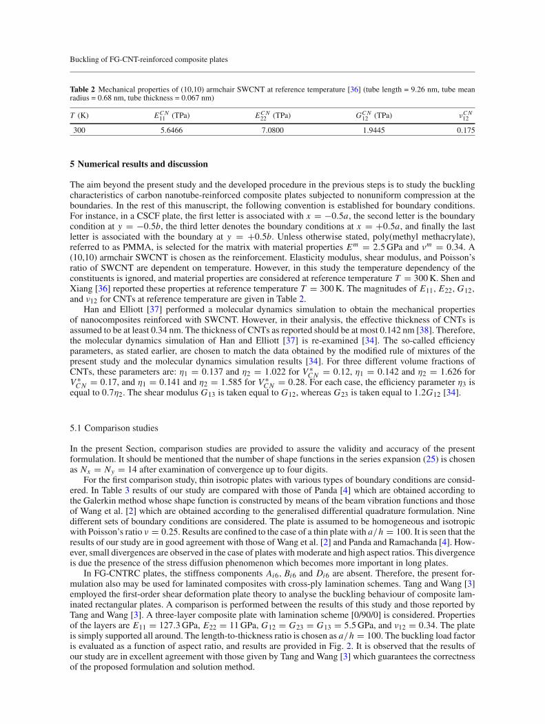
Table 2 Mechanical properties of (10,10) armchair SWCNT at reference temperature [36] (tube length = 9.26 nm, tube meanradius = 0.68 nm, tube thickness = 0.067 nm)
T (K) ECN11 (TPa) ECN
22 (TPa) GCN12 (TPa) νCN
12
300 5.6466 7.0800 1.9445 0.175
5 Numerical results and discussion
The aim beyond the present study and the developed procedure in the previous steps is to study the bucklingcharacteristics of carbon nanotube-reinforced composite plates subjected to nonuniform compression at theboundaries. In the rest of this manuscript, the following convention is established for boundary conditions.For instance, in a CSCF plate, the first letter is associated with x = −0.5a, the second letter is the boundarycondition at y = −0.5b, the third letter denotes the boundary conditions at x = +0.5a, and finally the lastletter is associated with the boundary at y = +0.5b. Unless otherwise stated, poly(methyl methacrylate),referred to as PMMA, is selected for the matrix with material properties Em = 2.5GPa and νm = 0.34. A(10,10) armchair SWCNT is chosen as the reinforcement. Elasticity modulus, shear modulus, and Poisson’sratio of SWCNT are dependent on temperature. However, in this study the temperature dependency of theconstituents is ignored, and material properties are considered at reference temperature T = 300K. Shen andXiang [36] reported these properties at reference temperature T = 300K. The magnitudes of E11, E22,G12,and ν12 for CNTs at reference temperature are given in Table 2.
Han and Elliott [37] performed a molecular dynamics simulation to obtain the mechanical propertiesof nanocomposites reinforced with SWCNT. However, in their analysis, the effective thickness of CNTs isassumed to be at least 0.34 nm. The thickness of CNTs as reported should be at most 0.142 nm [38]. Therefore,the molecular dynamics simulation of Han and Elliott [37] is re-examined [34]. The so-called efficiencyparameters, as stated earlier, are chosen to match the data obtained by the modified rule of mixtures of thepresent study and the molecular dynamics simulation results [34]. For three different volume fractions ofCNTs, these parameters are: η1 = 0.137 and η2 = 1.022 for V ∗
CN = 0.12, η1 = 0.142 and η2 = 1.626 forV ∗CN = 0.17, and η1 = 0.141 and η2 = 1.585 for V ∗
CN = 0.28. For each case, the efficiency parameter η3 isequal to 0.7η2. The shear modulus G13 is taken equal to G12, whereas G23 is taken equal to 1.2G12 [34].
5.1 Comparison studies
In the present Section, comparison studies are provided to assure the validity and accuracy of the presentformulation. It should be mentioned that the number of shape functions in the series expansion (25) is chosenas Nx = Ny = 14 after examination of convergence up to four digits.
For the first comparison study, thin isotropic plates with various types of boundary conditions are consid-ered. In Table 3 results of our study are compared with those of Panda [4] which are obtained according tothe Galerkin method whose shape function is constructed by means of the beam vibration functions and thoseof Wang et al. [2] which are obtained according to the generalised differential quadrature formulation. Ninedifferent sets of boundary conditions are considered. The plate is assumed to be homogeneous and isotropicwith Poisson’s ratio ν = 0.25. Results are confined to the case of a thin plate with a/h = 100. It is seen that theresults of our study are in good agreement with those of Wang et al. [2] and Panda and Ramachanda [4]. How-ever, small divergences are observed in the case of plates with moderate and high aspect ratios. This divergenceis due the presence of the stress diffusion phenomenon which becomes more important in long plates.
In FG-CNTRC plates, the stiffness components Ai6, Bi6 and Di6 are absent. Therefore, the present for-mulation also may be used for laminated composites with cross-ply lamination schemes. Tang and Wang [3]employed the first-order shear deformation plate theory to analyse the buckling behaviour of composite lam-inated rectangular plates. A comparison is performed between the results of this study and those reported byTang and Wang [3]. A three-layer composite plate with lamination scheme [0/90/0] is considered. Propertiesof the layers are E11 = 127.3GPa, E22 = 11GPa, G12 = G23 = G13 = 5.5GPa, and ν12 = 0.34. The plateis simply supported all around. The length-to-thickness ratio is chosen as a/h = 100. The buckling load factoris evaluated as a function of aspect ratio, and results are provided in Fig. 2. It is observed that the results ofour study are in excellent agreement with those given by Tang and Wang [3] which guarantees the correctnessof the proposed formulation and solution method.

Y. Kiani
Table 3 Critical buckling load parameter, λcr = N0,cr b2/(Dπ2) for isotropic homogeneous plates with ν = 0.25, a/h = 100and various boundary conditions
B.Cs. Source a/b
0.4 0.5 0.6 0.8 1.0 1.5 2.0 3.0
SSSS Present 9.6623 7.2727 6.0792 5.2102 5.2404 5.7254 5.5180 5.6100Panda [4] 9.654 7.271 6.078 5.211 5.242 5.704 5.478 5.547Wang et al. [2] 9.663 7.274 6.080 5.211 5.262 5.734 5.628 5.630
SSCS Present 17.0086 12.0225 9.3945 7.0415 6.2726 6.0499 5.8116 5.7320Panda [4] 17.02 12.03 9.401 7.035 6.254 6.023 5.768 5.671Wang et al. [2] 17.02 12.03 9.399 7.045 6.277 6.058 5.825 5.756
SCSS Present 10.0630 7.8873 6.9390 6.6957 7.5689 7.1201 7.4496 7.3886Panda [4] 10.06 7.877 6.938 6.692 7.551 7.104 7.412 7.373Wang et al. [2] 10.06 7.888 6.940 6.698 7.573 7.135 7.482 7.456
CSCS Present 30.6570 20.9983 15.8183 10.9450 9.0436 8.1411 7.1031 6.5484Panda [4] 30.65 21.01 15.82 10.95 9.032 8.127 7.063 6.495Wang et al. [2] 30.69 21.02 15.83 10.96 9.054 8.153 7.123 6.571
SCSC Present 10.5357 8.6636 8.0916 8.8850 9.1818 9.1164 9.0701 9.2234Panda [4] 10.52 8.652 8.087 8.877 9.172 9.114 9.053 9.117Wang et al. [2] 10.54 8.663 8.092 8.887 9.194 9.141 9.120 9.345
SSCC Present 17.2817 12.4921 10.0817 8.2286 7.9644 7.6625 7.5694 7.4773Panda [4] 17.28 12.49 10.07 8.231 7.957 7.645 7.390 7.451Wang et al. [2] 17.29 12.50 10.09 8.233 7.971 7.679 7.598 7.544
CCSC Present 17.5853 13.0519 10.9508 9.8155 9.8563 9.3636 9.3129 9.2285Panda [4] 17.58 13.04 10.94 9.814 9.847 9.340 8.309 9.205Wang et al. [2] 17.59 13.06 10.95 9.821 9.868 9.393 9.367 9.352
CCCS Present 30.8237 21.3628 16.4192 12.1103 10.8978 9.7383 9.2096 8.6092Panda [4] 30.54 21.35 16.42 12.12 10.88 9.735 9.185 8.571Wang et al. [2] 30.58 21.38 16.44 12.12 10.91 9.767 9.246 8.693
CCCC Present 31.0010 21.7776 17.1520 13.6988 13.5561 11.5851 11.1910 10.7853Panda [4] 31.01 21.74 17.15 13.66 13.55 11.58 11.17 10.77Wang et al. [2] 31.03 21.80 17.17 13.71 13.58 11.63 11.26 10.92
Fig. 2 Comparison of critical buckling load parameter kcr = N0b2/√D11D22 for a [0/90/0] cross-ply laminate with a/h = 100
and SSSS boundary conditions. Properties of the layers are E11 = 127.3GPa, E22 = 11GPa, G12 = G23 = G13 = 5.5GPa,and ν12 = 0.34. For the sake of comparison, results from Fig. 2 of Tang and Wang [3] are read from the graph
5.2 Parametric studies
In the whole of this Section, the critical buckling load parameter is defined as λcr = N0,cr b2/(π2Dm) whereDm is the flexural rigidity of a plate with the same thickness made of the pure polymeric matrix.

Buckling of FG-CNT-reinforced composite plates
Table 4 Critical buckling load parameter, λcr for FG-CNTRC plates with b/h = 50 and V ∗CN = 0.17
B.Cs. Pattern a/b
0.4 0.5 0.6 0.8 1.0 1.5 2.0 3.0
SSSS UD 263.2487 186.7302 138.9991 85.8715 59.1758 32.8725 26.0732 29.6035FG-X 353.8015 257.4665 194.6795 122.1227 84.3354 45.5584 34.2909 35.5179FG-O 153.5916 105.7362 77.4503 47.4787 33.2042 20.3205 18.3286 20.9085
CCFF UD 82.1086 56.3175 41.9304 27.3578 20.1206 11.9494 9.2753 8.4813FG-X 117.1918 80.6285 59.8639 38.7409 28.4249 16.5968 12.3487 10.7451FG-O 44.9350 31.0450 23.4075 15.5325 11.5154 7.3203 6.2787 6.0320
CFFF UD 81.7245 55.3839 40.3372 24.5427 16.5956 7.8515 4.5064 2.0273FG-X 116.8346 79.6928 58.1866 35.5386 24.1831 11.5853 6.6811 3.0154FG-O 44.4249 29.9926 21.8045 13.1404 8.7645 4.0620 2.3145 1.0357
CCCF UD 619.8760 493.2057 396.2550 267.1413 191.2850 104.0320 70.3500 39.5900FG-X 741.9548 615.1019 510.3278 359.2183 263.4763 145.7887 98.6666 56.3504FG-O 429.1780 319.2504 244.6712 156.0677 109.1598 59.4595 40.1736 22.3404
FCFC UD 3.6154 4.3592 5.2463 7.4560 10.2276 19.0801 23.1186 23.1133FG-X 4.0485 4.8839 5.8801 8.3643 11.4900 21.6625 30.7175 28.5792FG-O 3.3235 4.0107 4.8295 6.8607 9.3788 16.8356 15.7990 17.5136
CFSF UD 402.0449 298.1997 227.0166 141.8816 96.3571 46.7927 28.2518 14.4232FG-X 509.0304 392.4508 307.0391 198.3447 137.0507 67.6319 40.9221 20.8719FG-O 253.1082 177.5351 130.4007 78.3688 52.2836 25.1201 15.2488 7.7776
CCCC UD 619.8654 493.2214 396.3208 267.5472 192.5509 110.1589 86.6188 72.3625FG-X 741.9354 615.1135 510.3886 359.5975 264.7015 151.9828 115.2727 97.9234FG-O 429.1789 319.2788 244.7754 156.6488 110.7794 66.6287 58.1058 46.9493
FSFS UD 2.2908 2.4506 2.6381 3.1021 3.6870 5.6601 8.2499 11.8252FG-X 2.5670 2.7472 2.9584 3.4806 4.1392 6.3699 9.3403 15.5469FG-O 2.0962 2.2431 2.4157 2.8425 3.3789 5.1624 7.3791 8.2677
Fig. 3 Distribution of in-plane stresses prior to buckling for a square isotropic homogeneous plate with a/h = 100
Table 4 presents the critical buckling load parameter of FG-CNTRC plates for three different distributionpatterns, eight aspect ratios, and eight different sets of boundary conditions. The side-to-thickness ratio is setequal to b/h = 30, and the volume fraction of CNT is chosen as V ∗
CN = 0.17. Results of this Table indicate

Y. Kiani
Fig. 4 Buckling load parameter as a function of aspect ratio for FG-XCNTRCplateswith a/h = 30, various boundary conditions,and different volume fractions of CNTs

Buckling of FG-CNT-reinforced composite plates
Fig. 5 Buckling load parameter as a function of aspect ratio for UD CNTRC plates with a/h = 30, various boundary conditions,and different volume fractions of CNTs
Y. Kiani
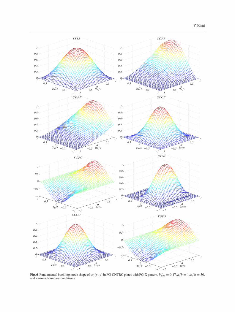
Fig. 6 Fundamental bucklingmode shape ofw0(x, y) in FG-CNTRC plates with FG-X pattern, V ∗CN = 0.17, a/b = 1, b/h = 50,
and various boundary conditions

Buckling of FG-CNT-reinforced composite plates
Fig. 7 Fundamental bucklingmode shape ofw0(x, y) in FG-CNTRC plates with FG-X pattern, V ∗CN = 0.17, a/b = 3, b/h = 50,
and various boundary conditions

Y. Kiani
that buckling loads of FG-X plates are higher than, in order, UD and FG-O plates. As expected, plates with alledges clamped have the highest buckling loads.
Figure 3 provides the in-plane stress distributions for an isotropic homogeneous plate subjected to par-abolic in-plane load. It is observed that the distribution of Nxx is different from the applied in-plane load atthe edge. Furthermore, Nyy and Nxy are both present, and are not equal to zero. This observation is unlike theobservations for plates subjected to uniform loading or the linearly varying loading. This feature is due to thestress diffusion phenomenon.
Figures 4 and 5 provide the critical buckling load parameter of FG-X and UD plates, respectively. In eachFigure, six types of boundary conditions and three different volume fractions of CNTs are considered. It isverified that the buckling loads of the plate enhance as the volume fraction of CNTs increases. This effectis due to the higher elasticity modulus of CNTs in comparison with the elasticity modulus of the polymericmatrix. Comparison of the results for Figs. 4 and 5 verifies that the critical buckling load of an FG-X plate ishigher than of a plate with UD pattern.
Buckling mode shapes for some selected geometrical characteristics and CNT properties are provided inFigs. 6 and 7. The presentations of these Figures are associated with the results of Table 4 with FG-X pattern.As seen from the fundamental buckling mode shape, the essential boundary conditions are satisfied at thesupports. Furthermore, a comparison between the results of Figs. 6 and 7 accepts that the buckled shape of theplate is highly sensitive to the aspect ratio of the plate.
6 Conclusions
Most of the available works on the subject of linear stability examination of FG-CNTRC plates are based onuniform edge compression. In this research, buckling loads and mode shapes of rectangular FG-CNTRC platessubjected to parabolic edge compression are obtained using a Ritz formulation. At first, the distribution ofin-plane loads within the plate domain is obtained by means of a two-dimensional formulation. Afterwards,an eigenvalue problem is formulated using the Chebyshev–Ritz method. Accuracy and correctness of thepresented formulation are demonstrated by comparison with the available data for isotropic homogeneousand cross-ply laminated composite plates. Afterwards, numerical results are given for a stability analysis ofFG-CNTRC plates subjected to parabolic loading. As shown, the distribution of in-plane loads within the plateis different from the applied parabolic loads at the boundary. Therefore, to reach a reliable design and to obtainthe critical buckling loads, prebuckling loads should be determined accurately. It is verified that, by usageof a proper distribution of CNTs in a matrix, the buckling loads of the plate may be enhanced significantly.Furthermore, enhancement of the matrix with more CNTs results in higher buckling loads for the plate.
References
1. Chen, X.L., Liew, K.M.: Buckling of rectangular functionally graded material plates subjected to nonlinearly distributedin-plane edge loads. Smart Mater. Struct. 13, 1430–1437 (2004)
2. Wang, X., Wang, X., Shi, X.: Accurate buckling loads of thin rectangular plates under parabolic edge compressions by thedifferential quadrature method. Int. J. Mech. Sci. 49, 447–453 (2007)
3. Tang, Y.,Wang, X.: Buckling of symmetrically laminated rectangular plates under parabolic edge compressions. Int. J. Mech.Sci. 53, 91–97 (2011)
4. Panda, S.K., Ramachandra, L.S.: Buckling of rectangular plates with various boundary conditions loaded by non-uniforminplane loads. Int. J. Mech. Sci. 52, 819–828 (2010)
5. Ramachandra, L.S., Panda, S.K.: Dynamic instability of composite plates subjected to non-uniform in-plane loads. J. SoundVib. 331, 53–65 (2012)
6. Ovesy, H.R., Fazilati, J.: Parametric instability analysis of laminated composite curved shells subjected to non-uniformin-plane load. Compos. Struct. 108, 449–455 (2014)
7. Dey, T., Kumar, R., Panda, S.K.: Postbuckling and postbuckled vibration analysis of sandwich plates under non-uniformmechanical edge loadings. Int. J. Mech. Sci. 115–116, 226–237 (2016)
8. Panda, S.K., Ramachandra, L.S.: Buckling and postbuckling behavior of cross-ply composite plate subjected to nonuniformin-plane loads. J. Eng. Mech. 137, 589–597 (2011)
9. Panda, S.K., Ramachandra, L.S.: Postbuckling analysis of cross-ply laminated cylindrical shell panels under parabolicmechanical edge loading. Thin Walled Struct. 48, 660–667 (2010)
10. Liew, K.M., Lei, Z.X., Zhang, L.W.: Mechanical analysis of functionally graded carbon nanotube reinforced composites: areview. Compos. Struct. 120, 90–97 (2015)
11. Kwon, H., Bradbury, C.R., Leparoux, M.: Fabrication of functionally graded carbon nanotube-reinforced aluminum matrixcomposite. Adv. Eng. Mater. 13, 325–329 (2013)

Buckling of FG-CNT-reinforced composite plates
12. Shen, H.S.: Nonlinear bending of functionally graded carbon nanotube reinforced composite plates in thermal environments.Compos. Struct. 91, 9–19 (2009)
13. Zhang, L.W., Lei, Z.X., Liew, K.M.: Buckling analysis of FG-CNT reinforced composite thick skew plates using an element-free approach. Compos. Part B Eng. 75, 36–46 (2015)
14. Zhang, L.W., Lei, Z.X., Liew, K.M.: Buckling analysis of functionally graded carbon nanotube-reinforced composite platesusing the element-free kp-Ritz method. Compos. Struct. 98, 160–168 (2013)
15. Malekzadeh, P., Shojaee,M.: Buckling analysis of quadrilateral laminated plates with carbon nanotubes reinforced compositelayers. Thin-walled Struct. 71, 108–118 (2013)
16. Lei, Z.X., Zhang, L.W., Liew, K.M.: Buckling of FG-CNT reinforced composite thick skew plates resting on Pasternakfoundations based on an element-free approach. Appl. Math. Comput. 266, 773–791 (2015)
17. Shen, H.S., Zhu, Z.H.: Buckling and postbuckling behavior of functionally graded nanotube-reinforced composite plates inthermal environments. Comput. Mater. Continua 18, 155–182 (2010)
18. Shen, H.S., Zhu, Z.H.: Postbuckling of sandwich plates with nanotube-reinforced composite face sheets resting on elasticfoundations. Eur. J. Mech. A Solids 35, 10–21 (2012)
19. Shi, D.L., Feng, X.Q., Huang, Y.Y., Hwang, K.C., Gao, H.J.: The effect of nanotube waviness and agglomeration on theelastic property of carbon nanotube reinforced composites. J. Eng. Mater. Technol. 126, 250–257 (2004)
20. Fidelus, J.D., Wiesel, E., Gojny, F.H., Schulte, K., Wagner, H.D.: Thermo-mechanical properties of randomly orientedcarbon/epoxy nanocomposites. Compos. Part A Appl. Sci. Manuf. 36, 1555–1561 (2005)
21. Jam, J.E., Kiani, Y.: Low velocity impact response of functionally graded carbon nanotube reinforced composite beams inthermal environment. Compos. Struct. 132, 35–43 (2015)
22. Kiani, Y.: Thermal postbuckling of temperature dependent sandwich beams with carbon nanotube reinforced face sheets. J.Therm. Stress. 39, 1098–1110 (2016)
23. Mirzaei, M., Kiani, Y.: Snap-through phenomenon in a thermally postbuckled temperature dependent sandwich beam withFG-CNTRC face sheets. Compos. Struct. 134, 1004–1013 (2015)
24. Mirzaei, M., Kiani, Y.: Nonlinear free vibration of temperature dependent sandwich beams with carbon nanotube reinforcedface sheets. Acta Mech. 227, 1869–1884 (2016)
25. Mirzaei, M., Kiani, Y.: Thermal buckling of temperature dependent FG-CNT reinforced composite plates. Meccanica 51,2185–2201 (2016)
26. Mirzaei, M., Kiani, Y.: Free vibration of functionally graded carbon-nanotube-reinforced composite plates with cutout.Beilstein J. Nanotechnol. 7, 511–523 (2016)
27. Kiani, Y.: Free vibration of carbon nanotube reinforced composite plate on point supports using Lagrangian multipliers.Meccanica. doi:10.1007/s11012-016-0466-3
28. Mirzaei, M., Kiani, Y.: Free vibration of functionally graded carbon nanotube reinforced composite cylindrical panels.Compos. Struct. 142, 45–56 (2016)
29. Mirzaei, M., Kiani, Y.: Vibration analysis of functionally graded carbon nanotube-reinforced composite shell structures. ActaMech. 227, 581-559 (2016)
30. Pouresmaeeli, S., Fazelzadeh, S. A.: Frequency analysis of doubly curved functionally graded carbon nanotube-reinforcedcomposite panels. Acta Mech. doi:10.1007/s00707-016-1647-9
31. Jam, J.E., Kiani, Y.: Buckling of pressurized functionally graded carbon nanotube reinforced conical shells. Compos. Struct.125, 586–595 (2015)
32. Mirzaei, M., Kiani, Y.: Thermal buckling of temperature dependent FG-CNT reinforced composite conical shells. Aerosp.Sci. Technol. 47, 42–53 (2015)
33. Kiani, Y.: Torsional vibration of functionally graded carbon nanotube reinforced conical shells. Sci. Eng. Compos. Mater.doi:10.1515/secm-2015-0454
34. Shen, H.S.: Postbuckling of nanotube-reinforced composite cylindrical shells in thermal environments, part I: axially-loadedshells. Compos. Struct. 93, 2096–2108 (2011)
35. Reddy, J.N.: Mechanics of Laminated Composite Plates and Shells, Theory and Application. CRC Press, Boca Raton (2003)36. Shen, H.S., Xiang, Y.: Nonlinear analysis of nanotube reinforced composite beams resting on elastic foundations in thermal
environments. Eng. Struct. 56, 698–708 (2013)37. Han,Y., Elliott, J.:Molecular dynamics simulations of the elastic properties of polymer/carbon nanotube composites. Comput.
Mater. Sci. 39, 315–323 (2007)38. Wang, C.Y., Zhang, L.C.: A critical assessment of the elastic properties and effective wall thickness of single-walled carbon
nanotubes. Nanotechnology 19, 075705 (2008)