Embed Size (px)
Citation preview

Waters Xevo TQ MSOperator’s Overview and Maintenance Guide
71500130002 / Revision D
Copyright © Waters Corporation 2013.All rights reserved

ii February 11, 2013, 71500130002 Rev. D
General Information
Copyright notice
© 2013 WATERS CORPORATION. PRINTED IN THE UNITED STATES OF AMERICA AND IN IRELAND. ALL RIGHTS RESERVED. THIS DOCUMENT OR PARTS THEREOF MAY NOT BE REPRODUCED IN ANY FORM WITHOUT THE WRITTEN PERMISSION OF THE PUBLISHER.
The information in this document is subject to change without notice and should not be construed as a commitment by Waters Corporation. Waters Corporation assumes no responsibility for any errors that may appear in this document. This document is believed to be complete and accurate at the time of publication. In no event shall Waters Corporation be liable for incidental or consequential damages in connection with, or arising from, its use. For the most recent revision of this document, consult the Waters Web site (waters.com).
Trademarks
ACQUITY, ACQUITY UPLC, Connections INSIGHT, ESCi, MassLynx, nanoACQUITY UPLC, UltraPerformance LC, UNIFI, UPLC, Xevo, Waters, and Waters Quality Parts are registered trademarks of Waters Corporation, and IntelliStart, NanoFlow, OpenLynx, ScanWave, T-Wave, TargetLynx, “THE SCIENCE OF WHAT'S POSSIBLE.”, and ZSpray are trademarks of Waters Corporation.
GELoader is a registered trademark of New Brunswick Scientific, Co., Inc.
Phillips is a registered trademark of Phillips Screw Company, Inc.
PEEK is a trademark of Victrex Corporation.
snoop and Swagelok are registered trademarks of Swagelok Company.
Teflon and Viton are registered trademarks of DuPont.
Varian is a trademark of Varian, Inc.
Xylan is a registered trademark of Whitford Corporation.
Other registered trademarks or trademarks are the sole property of their owners.
February 11, 2013, 71500130002 Rev. D iii

Customer comments
Waters’ Technical Communications organization invites you to report any errors that you encounter in this document or to suggest ideas for otherwise improving it. Help us better understand what you expect from our documentation so that we can continuously improve its accuracy and usability.
We seriously consider every customer comment we receive. You can reach us at [email protected].
Contacting Waters
Contact Waters® with enhancement requests or technical questions regarding the use, transportation, removal, or disposal of any Waters product. You can reach us via the Internet, telephone, or conventional mail.
Waters contact information:
Contacting medium Information
Internet The Waters Web site includes contact information for Waters locations worldwide. Visit www.waters.com.
Telephone and fax From the USA or Canada, phone 800 252-HPLC, or fax 508 872 1990.For other locations worldwide, phone and fax numbers appear in the Waters Web site.
Conventional mail Waters Corporation34 Maple StreetMilford, MA 01757USA
iv February 11, 2013, 71500130002 Rev. D
Safety considerations
Some reagents and samples used with Waters instruments and devices can pose chemical, biological, or radiological hazards (or any combination thereof). You must know the potentially hazardous effects of all substances you work with. Always follow Good Laboratory Practice, and consult your organization’s safety representative for guidance.
Considerations specific to the Xevo TQ MS
Solvent leakage hazard
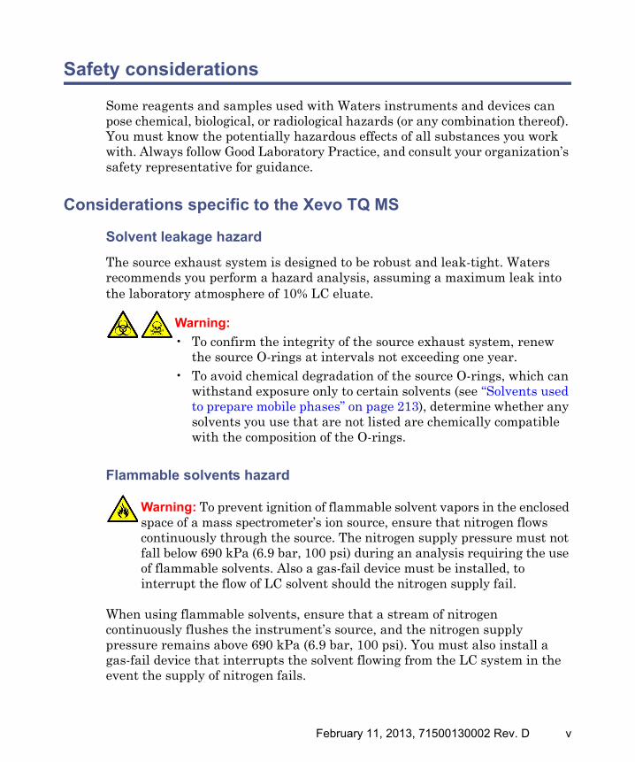
The source exhaust system is designed to be robust and leak-tight. Waters recommends you perform a hazard analysis, assuming a maximum leak into the laboratory atmosphere of 10% LC eluate.
Flammable solvents hazard
When using flammable solvents, ensure that a stream of nitrogen continuously flushes the instrument’s source, and the nitrogen supply pressure remains above 690 kPa (6.9 bar, 100 psi). You must also install a gas-fail device that interrupts the solvent flowing from the LC system in the event the supply of nitrogen fails.
Warning:
• To confirm the integrity of the source exhaust system, renew the source O-rings at intervals not exceeding one year.
• To avoid chemical degradation of the source O-rings, which can withstand exposure only to certain solvents (see “Solvents used to prepare mobile phases” on page 213), determine whether any solvents you use that are not listed are chemically compatible with the composition of the O-rings.
Warning: To prevent ignition of flammable solvent vapors in the enclosed space of a mass spectrometer’s ion source, ensure that nitrogen flows continuously through the source. The nitrogen supply pressure must not fall below 690 kPa (6.9 bar, 100 psi) during an analysis requiring the use of flammable solvents. Also a gas-fail device must be installed, to interrupt the flow of LC solvent should the nitrogen supply fail.
February 11, 2013, 71500130002 Rev. D v

High temperature hazard
Xevo TQ MS high temperature hazard:
Warning: To avoid burn injuries, avoid touching the source ion block assembly when operating or servicing the instrument.
TP03127
TQMS
TQMS
Source ion block assembly
vi February 11, 2013, 71500130002 Rev. D

Hazards associated with removing an instrument from service
When you remove the instrument from use to repair or dispose of it, you must decontaminate all of its vacuum areas. These are the areas in which you can expect to encounter the highest levels of contamination:
• Source interior
• Waste tubing
• Exhaust system
• Rotary pump oil (where applicable)
The need to decontaminate other vacuum areas of the instrument depends on the kinds of samples the instrument analyzed and their levels of concentration. Do not dispose of the instrument or return it to Waters for repair until the authority responsible for approving its removal from the premises specifies the extent of decontamination required and the level of residual contamination permissible. That authority must also prescribe the method of decontamination to be used and the appropriate protection for personnel undertaking the decontamination process.
You must handle items such as syringes, fused silica lines, and borosilicate tips used to carry sample into the source area in accordance with laboratory procedures for contaminated vessels and sharps. To avoid contamination by carcinogens, toxic substances, or biohazards, you must wear chemical-resistant gloves when handling or disposing of used oil.
Warning: To avoid personal contamination with biohazards, toxic materials, and corrosive materials, wear chemical-resistant gloves during all phases of instrument decontamination.
Warning: To avoid puncture injuries, handle syringes, fused silica lines, and borosilicate tips with extreme care.
February 11, 2013, 71500130002 Rev. D vii

FCC radiation emissions notice
Changes or modifications not expressly approved by the party responsible for compliance, could void the users authority to operate the equipment. This device complies with Part 15 of the FCC Rules. Operation is subject to the following two conditions: (1) this device may not cause harmful interference, and (2) this device must accept any interference received, including interference that may cause undesired operation.
Canada spectrum management emissions notice
This class A digital product apparatus complies with Canadian ICES-003.
Cet appareil numérique de la classe A est conforme à la norme NMB-003.
Electrical power safety notice
Do not position the instrument so that it is difficult to operate the disconnecting device.
Safety hazard symbol notice
Documentation needs to be consulted in all cases where the symbol is used to find out the nature of the potential hazard and any actions which have to be taken.
Equipment misuse notice
If the equipment is used in a manner not specified by the manufacturer, the protection provided by the equipment may be impaired.
Safety advisories
Consult Appendix A for a comprehensive list of warning and caution advisories.
viii February 11, 2013, 71500130002 Rev. D

Operating this instrument
When operating this instrument, follow standard quality-control (QC) procedures and the guidelines presented in this section.
Applicable symbols
Audience and purpose
This guide is for operators of varying levels of experience. It gives an overview of the instrument, and explains how to prepare it, change its modes of operation, and maintain it.
Symbol Definition
Manufacturer
Authorized representative of the European Community
Confirms that a manufactured product complies with all applicable European Community directives
Australia C-Tick EMC compliant
Confirms that a manufactured product complies with all applicable United States and Canadian safety requirements
Consult instructions for use
Contact Waters Corporation for the correct disposal and recycling instructions
February 11, 2013, 71500130002 Rev. D ix
Intended use of the Xevo TQ MS
Waters designed the tandem quadrupole Xevo® TQ MS for use as a research tool to deliver authenticated mass measurement in both MS and MS/MS modes.
Calibrating
To calibrate LC systems, follow acceptable calibration methods using at least five standards to generate a standard curve. The concentration range for standards should include the entire range of QC samples, typical specimens, and atypical specimens.
When calibrating mass spectrometers, consult the calibration section of the operator’s guide for the instrument you are calibrating. In cases where an overview and maintenance guide, not operator’s guide, accompanies the instrument, consult the instrument’s online Help system for calibration instructions.
Quality-control
Routinely run three QC samples that represent subnormal, normal, and above-normal levels of a compound. Ensure that QC sample results fall within an acceptable range, and evaluate precision from day to day and run to run. Data collected when QC samples are out of range might not be valid. Do not report these data until you are certain that the instrument performs satisfactorily.
When analyzing samples from a complex matrix such as soil, tissue, serum/plasma, whole blood, and other sources, note that the matrix components can adversely affect LC/MS results, enhancing or suppressing ionization. To minimize these matrix effects, Waters recommends you adopt the following measures:
• Prior to the instrumental analysis, use appropriate sample pretreatment such as protein precipitation, liquid/liquid extraction (LLE), or solid phase extraction (SPE) to remove matrix interferences.
• Whenever possible, verify method accuracy and precision using matrix-matched calibrators and QC samples.
• Use one or more internal standard compounds, preferably isotopically labeled analytes.
x February 11, 2013, 71500130002 Rev. D
ISM classification
ISM Classification: ISM Group 1 Class A
This classification has been assigned in accordance with IEC CISPR 11 Industrial Scientific and Medical (ISM) instruments requirements. Group 1 products apply to intentionally generated and/or used conductively coupled radio-frequency energy that is necessary for the internal functioning of the equipment. Class A products are suitable for use in commercial (that is, nonresidential) locations and can be directly connected to a low voltage, power-supply network.
EC authorized representative
Waters Corporation (Micromass UK Ltd.)Floats RoadWythenshaweManchester M23 9LZUnited Kingdom
Telephone: +44-161-946-2400
Fax: +44-161-946-2480
Contact: Quality manager
February 11, 2013, 71500130002 Rev. D xi

xii February 11, 2013, 71500130002 Rev. D

Table of Contents
General Information .................................................................................... iii
Copyright notice .................................................................................................. iii
Trademarks ........................................................................................................... iii
Customer comments ............................................................................................ iv
Contacting Waters ............................................................................................... iv
Safety considerations ........................................................................................... v Considerations specific to the Xevo TQ MS........................................................ v FCC radiation emissions notice ...................................................................... viii Canada spectrum management emissions notice .......................................... viii Electrical power safety notice ......................................................................... viii Safety hazard symbol notice............................................................................ viii Equipment misuse notice ................................................................................ viii Safety advisories .............................................................................................. viii
Operating this instrument ................................................................................. ix Applicable symbols ............................................................................................. ix Audience and purpose......................................................................................... ix Intended use of the Xevo TQ MS ........................................................................ x Calibrating ........................................................................................................... x Quality-control ..................................................................................................... x
ISM classification ................................................................................................. xi ISM Classification: ISM Group 1 Class A ......................................................... xi
EC authorized representative ........................................................................... xi
1 Waters Xevo TQ MS Overview .............................................................. 21
Waters Xevo TQ MS ........................................................................................... 22 ACQUITY Xevo TQ MS UPLC/MS systems..................................................... 24 Non-ACQUITY devices for use with the Xevo TQ MS..................................... 25 Software and data system ................................................................................. 26
February 11, 2013, 71500130002 Rev. D xiii

Ionization techniques and source probes .................................................... 27 Electrospray ionization (ESI) ............................................................................ 27 Combined electrospray ionization and atmospheric pressure chemical ionization (ESCi) ................................................................................................ 27 Atmospheric pressure chemical ionization (APCI) .......................................... 27 Dual-mode APPI/APCI source........................................................................... 28 NanoFlow ESI source ........................................................................................ 28
IntelliStart Fluidics system ............................................................................. 29 Overview............................................................................................................. 29 System components ........................................................................................... 30 System operation ............................................................................................... 30
Ion optics .............................................................................................................. 31
MS operating modes .......................................................................................... 32
MS/MS operating modes ................................................................................... 33 Product (daughter) ion mode............................................................................. 34 Precursor (parent) ion mode.............................................................................. 34 Multiple reaction monitoring mode .................................................................. 35 Constant neutral loss mode............................................................................... 36 ScanWave daughter scan mode......................................................................... 37
Leak sensors ........................................................................................................ 38
Vacuum system ................................................................................................... 38
Rear panel ............................................................................................................ 39
2 Preparing the Mass Spectrometer for Operation ............................ 41
Starting the mass spectrometer ..................................................................... 42 Verifying the instrument’s state of readiness .................................................. 45 Monitoring the mass spectrometer LEDs......................................................... 45 Tuning and calibration information ................................................................. 45 Running the mass spectrometer at high flow rates ......................................... 46
Preparing the IntelliStart Fluidics system .................................................. 47 Installing the reservoir bottles.......................................................................... 47 Purging the infusion pump................................................................................ 48
xiv February 11, 2013, 71500130002 Rev. D
Rebooting the mass spectrometer .................................................................. 49
Leaving the mass spectrometer ready for operation ................................ 50
Emergency shutdown of the mass spectrometer ....................................... 50
3 Changing the Mode of Operation ........................................................ 51
ESI mode .............................................................................................................. 52 Installing the ESI probe .................................................................................... 52 Removing the ESI probe.................................................................................... 56
ESCi mode ............................................................................................................ 57 Optimizing the ESI probe for ESCi operation.................................................. 57
APCI mode ........................................................................................................... 57 Installing the APCI probe ................................................................................. 58 Removing the APCI probe ................................................................................. 60
Combined APPI/APCI source .......................................................................... 61 APPI operation................................................................................................... 61 APCI operation................................................................................................... 62 Dual-mode operation ......................................................................................... 63 The combined APPI/APCI source components ................................................. 64 Installing the Combined APPI/APCI Source software..................................... 66 Removing the APCI probe and APPI source enclosure.................................... 68
NanoFlow ESI source ........................................................................................ 69 Installing the NanoFlow source ........................................................................ 70 Fitting a borosilicate glass capillary (nanovial) ............................................... 73 Positioning the borosilicate glass capillary tip................................................. 77 Restarting a stalled borosilicate glass capillary electrospray ......................... 77
February 11, 2013, 71500130002 Rev. D xv

4 Maintenance Procedures ...................................................................... 79
Maintenance schedule ...................................................................................... 81
Spare parts .......................................................................................................... 82
Troubleshooting with Connections INSIGHT ............................................. 83
Safety and handling .......................................................................................... 84
Preparing the instrument for working on the source .............................. 85
Removing and refitting the source enclosure ............................................. 87 Removing the source enclosure from the instrument ...................................... 87 Fitting the source enclosure to the instrument................................................ 89
Installing and removing the corona pin ....................................................... 90 Installing the corona pin in the source ............................................................. 90 Removing the corona pin from the source ........................................................ 93
Operating the source isolation valve ............................................................ 94
Removing O-rings and seals ............................................................................ 97
Cleaning the instrument case ......................................................................... 98
Emptying the nitrogen exhaust trap bottle ................................................. 98
Inspecting the Varian roughing pump oil level ........................................ 101
Adding oil to the Varian roughing pump ................................................... 102
Replacing the Varian roughing pump oil and oil mist filter ................. 104 Emptying the roughing pump oil .................................................................... 104 Replacing the oil mist filter............................................................................. 106 To refill the pump with oil............................................................................... 108
Cleaning the source components ................................................................. 110
Cleaning the sampling cone assembly ........................................................ 111 Removing the sampling cone assembly from the source ............................... 111 Disassembling the sampling cone assembly................................................... 113 Cleaning the sample cone and cone gas nozzle .............................................. 115 Assembling the sampling cone assembly........................................................ 117
xvi February 11, 2013, 71500130002 Rev. D

Fitting the sampling cone assembly to the source ......................................... 118
Cleaning the extraction cone ........................................................................ 120 Removing the ion block assembly from the source assembly ........................ 120 Removing the extraction cone from the ion block .......................................... 122 Cleaning the extraction cone........................................................................... 124 Fitting the extraction cone to the ion block.................................................... 126 Fitting the ion block assembly to the source assembly.................................. 126
Cleaning the ion block assembly .................................................................. 128 Disassembling the source ion block assembly................................................ 128 Cleaning the ion block components ................................................................ 136 Assembling the source ion block assembly..................................................... 138
Cleaning the source hexapole assembly ..................................................... 140 Removing the ion block assembly, ion block support, and hexapole from the source assembly ......................................................................................... 140 Cleaning the hexapole assembly..................................................................... 142 Fitting the hexapole assembly, PEEK ion block support, and ion block assembly to the source assembly .................................................................... 144
Replacing the ESI probe tip and gasket ..................................................... 146 Removing the ESI probe tip and gasket ......................................................... 146 Fitting the ESI probe tip and gasket .............................................................. 149
Replacing the ESI probe sample capillary ................................................ 150 Removing the existing capillary...................................................................... 150 Installing the new capillary ............................................................................ 155
Cleaning the APCI probe tip ......................................................................... 158
Replacing the APCI probe sample capillary ............................................. 159 Removing the existing capillary...................................................................... 159 Installing the new capillary ............................................................................ 162
Cleaning or replacing the corona pin ......................................................... 165
Replacing the APCI probe heater ................................................................ 166 Removing the APCI probe heater ................................................................... 166 Fitting the new APCI probe heater ................................................................ 169
February 11, 2013, 71500130002 Rev. D xvii

Replacing the ion block source heater ....................................................... 170
Replacing the source assembly seals .......................................................... 174 Removing the probe adjuster assembly probe and source enclosure seals... 174 Fitting the new source enclosure and probe adjuster assembly probe seals 177
Replacing the air filter ................................................................................... 179
APPI/APCI source—changing the UV lamp bulb ..................................... 181
APPI/APCI source—Cleaning the lamp window ...................................... 184
APPI/APCI source—Replacing the APPI lamp drive seals .................... 185 Removing the APPI lamp drive assembly seals ............................................. 185 Fitting the new APPI lamp drive assembly O-rings ...................................... 191
A Safety Advisories .................................................................................. 195
Warning symbols .............................................................................................. 196 Specific warnings ............................................................................................. 197
Caution advisory .............................................................................................. 200
Warnings that apply to all Waters instruments and devices ................. 201
Warnings that address the replacing of fuses ........................................... 206
Electrical and handling symbols .................................................................. 208 Electrical symbols ............................................................................................ 208 Handling symbols ............................................................................................ 209
B Materials of Construction and Compliant Solvents ..................... 211
Preventing contamination ............................................................................. 212
Items exposed to solvent ................................................................................ 212
Solvents used to prepare mobile phases .................................................... 213
C External Connections .......................................................................... 215
External wiring and vacuum connections ................................................. 216
Connecting the Varian oil-filled roughing pump ..................................... 217 Making the electrical connections to the Varian oil-filled roughing pump .. 222
xviii February 11, 2013, 71500130002 Rev. D

Connecting the Edwards oil-free roughing pump ................................... 223 Making the electrical connections for the Edwards oil-free roughing pump 228
Connecting to the nitrogen gas supply ....................................................... 229
Connecting to the collision cell gas supply ............................................... 230
Connecting the nitrogen exhaust line ........................................................ 231
Connecting the liquid waste line ................................................................. 234
Connecting the workstation .......................................................................... 236
Connecting Ethernet cables .......................................................................... 237
Input/output signal connectors .................................................................... 237 Making signal connections .............................................................................. 240
Connecting to the electricity source ........................................................... 243
D Plumbing the IntelliStart Fluidics System .................................... 245
Preventing contamination ............................................................................. 246
Plumbing schematic ........................................................................................ 246
Pipe specifications ........................................................................................... 247
February 11, 2013, 71500130002 Rev. D xix

xx February 11, 2013, 71500130002 Rev. D

1 Waters Xevo TQ MS Overview
This chapter describes the instrument, including its controls and connections for gas and plumbing.
Contents:
Topic Page
Waters Xevo TQ MS......................................................................... 22
Ionization techniques and source probes ........................................ 27
IntelliStart Fluidics system............................................................. 29
Ion optics .......................................................................................... 31
MS operating modes ........................................................................ 32
MS/MS operating modes.................................................................. 33
Leak sensors..................................................................................... 38
Vacuum system ................................................................................ 38
Rear panel ........................................................................................ 39
February 11, 2013, 71500130002 Rev. D 21
1 Waters Xevo TQ MS Overview
Waters Xevo TQ MS
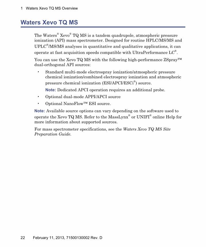
The Waters® Xevo® TQ MS is a tandem quadrupole, atmospheric pressure ionization (API) mass spectrometer. Designed for routine HPLC/MS/MS and UPLC®/MS/MS analyses in quantitative and qualitative applications, it can operate at fast acquisition speeds compatible with UltraPerformance LC®.
You can use the Xevo TQ MS with the following high-performance ZSpray™ dual-orthogonal API sources:
• Standard multi-mode electrospray ionization/atmospheric pressure chemical ionization/combined electrospray ionization and atmospheric pressure chemical ionization (ESI/APCI/ESCi®) source.
Note: Dedicated APCI operation requires an additional probe.
• Optional dual-mode APPI/APCI source
• Optional NanoFlow™ ESI source.
Note: Available source options can vary depending on the software used to operate the Xevo TQ MS. Refer to the MassLynx® or UNIFI® online Help for more information about supported sources.
For mass spectrometer specifications, see the Waters Xevo TQ MS Site Preparation Guide.
22 February 11, 2013, 71500130002 Rev. D

Waters Xevo TQ MS
Waters Xevo TQ MS:
IntelliStart technology
IntelliStart™ technology monitors LC/MS/MS performance and reports when the mass spectrometer is ready for use.
The software automatically tunes and mass calibrates the mass spectrometer, displays performance readbacks, and enables simplified setup of the system for use in routine analytical and open access applications. (See page 26.)
The IntelliStart Fluidics system is built into the mass spectrometer. It delivers sample directly to the MS probe from the LC column or from three integral reservoirs. The integral reservoirs can also deliver sample through direct or combined infusion so that you can optimize instrument performance at analytical flow rates.
Recommendation: Use reservoir A for the calibrant solution, reservoir B for tuning compounds, and reservoir C for analyte/optimization solution.
A fourth reservoir contains solvent for automated flushing of the solvent delivery system.
See the mass spectrometer’s online Help for further details on IntelliStart technology.
TQMS
TQMS
February 11, 2013, 71500130002 Rev. D 23

1 Waters Xevo TQ MS Overview
ACQUITY Xevo TQ MS UPLC/MS systems
The Waters Xevo TQ MS is compatible with the ACQUITY UPLC® systems; if you are not using an ACQUITY UPLC system, refer to the documentation relevant to your LC system. See “Non-ACQUITY devices for use with the Xevo TQ MS” on page 25.
The ACQUITY® Xevo TQ MS UPLC/MS system includes an ACQUITY UPLC system and the Waters Xevo TQ MS.
ACQUITY UPLC system
The ACQUITY UPLC system includes a binary solvent manager, sample manager, column heater, optional sample organizer, optional detectors, a specialized ACQUITY UPLC column, and software to control the system.
For further instruction, see the ACQUITY UPLC System Operator’s Guide or Controlling Contamination in LC/MS Systems (part number 715001307). You can find these documents on http://www.waters.com; click Services and Support > Support.
Waters ACQUITY Xevo TQ MS UPLC/MS system:
Sample organizer (optional)
Solvent tray
Column heater
Xevo TQ MS
Sample managerBinary solvent manager Access door to the fluidics pump
Access door to the fluidics valve
ESI probe high voltage connector
Probe
Source interface sliding door
Source enclosure
Source enclosure release
24 February 11, 2013, 71500130002 Rev. D

Waters Xevo TQ MS
nanoACQUITY UPLC Xevo TQ MS UPLC/MS system
Similar to the ACQUITY UPLC system, the nanoACQUITY uses the optional NanoFlow source on the Xevo TQ MS. It is designed for capillary-to-nano-scale separations. Its sensitivity, resolution, and reproducibility well suit it for biomarker discovery and proteomics applications, including protein identification and characterization.
This system is optimized for high-resolution separations at precise nanoflow rates. With closed loop control, those rates range between 0.20 and 5.00 µL/min. With open loop control and nanoACQUITY UPLC® columns of internal diameters ranging from 75 µm to 1 mm, the flow rates can extend to 100 µL/min. The column hardware and the matched outlet tubing can withstand pressure of as much as 69,000 kPa (690 bar, 10,000 psi). The column dimensions allow optimal MS-compatible flow rates, and matched outlet tubing minimizes the effect of extra-column volume.
For further instruction, see the nanoACQUITY UPLC System Operator’s Guide or Controlling Contamination in LC/MS Systems (part number 715001307). You can find these documents on http://www.waters.com; click Services and Support > Support.
Non-ACQUITY devices for use with the Xevo TQ MS
The following non-ACQUITY LC devices are validated for use with the Xevo TQ MS:
• Waters Alliance 2695 separations module
• Waters Alliance 2795 separations module
• Waters 2998 PDA detector
• Waters 2487 UV detector
• Waters 1525µ binary gradient pump + 2777 autosampler
• Spark Holland Symbiosis
February 11, 2013, 71500130002 Rev. D 25

1 Waters Xevo TQ MS Overview
Software and data system
MassLynx v4.1 or UNIFI software can control the mass spectrometer. See page 26 for more information about those applications.
Both MassLynx and UNIFI software enable these major operations:
• Configuring the instrument.
• Creating LC and MS/MS methods that define operating parameters for a run.
• Using IntelliStart software to tune and mass calibrate the mass spectrometer.
• Running samples.
• Monitoring the run.
• Acquiring data.
• Processing data.
• Reviewing data.
• Printing data.
MassLynx v4.1
MassLynx software acquires, analyzes, manages, and distributes mass spectrometry, ultraviolet (UV), evaporative light scattering, and analog data. OpenLynx™ and TargetLynx™ application managers are included as standard software with MassLynx.
See the MassLynx v4.1 user documentation and online Help for information about using MassLynx software.
You configure settings, monitor performance, run diagnostic tests, and maintain the system and its modules via the MassLynx Instrument Console application.
The Instrument Console software, which functions independently of MassLynx software, does not recognize or control data systems.
UNIFI v1.6
UNIFI software integrates mass spectrometry, UPLC chromatography, and informatics data work flows.
See UNIFI v1.6 user documentation and online Help for more information about using UNIFI software.
26 February 11, 2013, 71500130002 Rev. D

Ionization techniques and source probes
Ionization techniques and source probes
Note: Available source options can vary depending on the software used to operate the Xevo TQ MS. Refer to the MassLynx or UNIFI online Help for more information about supported sources.
Electrospray ionization (ESI)
In electrospray ionization (ESI), a strong electrical charge is applied to the eluent as it emerges from a nebulizer. The droplets that compose the resultant aerosol undergo a reduction in size (solvent evaporation). As solvent continues to evaporate, the charge density increases until the droplet surfaces eject ions (ion evaporation). The ions can be singly or multiply charged.
The instrument can accommodate eluent flow rates of up to 2 mL/min.
Combined electrospray ionization and atmospheric pressure chemical ionization (ESCi)
Combined electrospray ionization and atmospheric pressure chemical ionization (ESCi) is supplied as standard equipment on the mass spectrometer. In ESCi, the standard ESI probe is used in conjunction with a corona pin to allow alternating acquisition of ESI and APCI ionization data, facilitating high throughput and wider compound coverage.
See “ESCi mode” on page 57 for further details.
Atmospheric pressure chemical ionization (APCI)
A dedicated high-performance atmospheric pressure chemical ionization (APCI) probe is offered as an option. APCI produces singly charged protonated or deprotonated molecules for a broad range of nonvolatile analytes.
The APCI interface consists of the ESI/APCI/ESCi enclosure fitted with a corona pin and an APCI probe.
See “APCI mode” on page 57 for further details.
February 11, 2013, 71500130002 Rev. D 27

1 Waters Xevo TQ MS Overview
Dual-mode APPI/APCI source
The optional, combined atmospheric pressure photoionization/atmospheric pressure chemical ionization (APPI/APCI) source comprises an APCI probe and the APPI lamp drive assembly. The APPI lamp drive assembly, which itself comprises a UV lamp and a repeller electrode. In addition, a specially-shaped, dual, APPI/APCI corona pin can be used. You can operate the source in APPI, APCI, or dual mode, which switches rapidly between APPI and APCI ionization modes.
NanoFlow ESI source
NanoFlow is the name given to several techniques that use low flow rate electrospray ionization (ESI). The NanoFlow source allows electrospray ionization in the flow rate range 5 to 1000 nL/min. For a given sample concentration, the ion currents observed approximate those seen in normal flow rate electrospray. However, for similar experiments, NanoFlow’s significant reduction in sample consumption accompanies significant increases in sensitivity.
The following options are available for the spraying capillary:
• Universal nebulizer sprayer (Nano-LC).
This option is for flow injection or for coupling to nano-UPLC and uses a pump to regulate the flow rate downward to 100 nL/min. If a syringe pump is used, a gas-tight syringe is necessary to effect correct flow rates without leakage. A volume of 250 µL is recommended.
• Borosilicate glass capillaries (nanovials).
Metal-coated, glass capillaries allow the lowest flow rates. Usable for one sample, they must then be discarded.
• Capillary Electrophoresis (CE) or Capillary Electrochromatography (CEC) sprayer.
This option uses a make-up liquid at the capillary tip, which allows a stable electrospray to occur. The make-up flow rate is less than 1 µL/min.
28 February 11, 2013, 71500130002 Rev. D

IntelliStart Fluidics system
IntelliStart Fluidics system
Overview
The IntelliStart Fluidics system is a solvent delivery system built into the mass spectrometer. It delivers sample directly to the MS probe in one of three ways:
• From the LC column.
• From three integral reservoirs. Use standard reservoir bottles (30 mL) for instrument setup and calibration. Use low-volume vials (1.5 mL) to infuse smaller volumes. See “Installing the reservoir bottles” on page 47.
Tip: The reservoirs can also deliver sample through direct or combined infusion to enable optimization at analytical flow rates.
• From a wash reservoir, which contains solvent for automated flushing of the instrument’s solvent delivery system.
Fluidics system:
Column
Diverter valve
LC
Probe
Pump
Reservoirs
A B CWash
reservoir
6-port selector valve
Sample loop
Waste
reservoir
February 11, 2013, 71500130002 Rev. D 29
1 Waters Xevo TQ MS Overview
System components
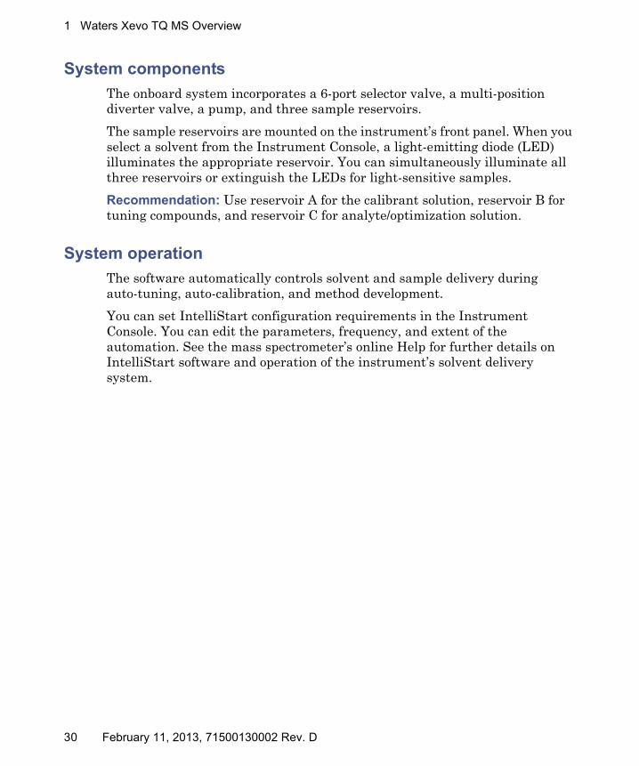
The onboard system incorporates a 6-port selector valve, a multi-position diverter valve, a pump, and three sample reservoirs.
The sample reservoirs are mounted on the instrument’s front panel. When you select a solvent from the Instrument Console, a light-emitting diode (LED) illuminates the appropriate reservoir. You can simultaneously illuminate all three reservoirs or extinguish the LEDs for light-sensitive samples.
Recommendation: Use reservoir A for the calibrant solution, reservoir B for tuning compounds, and reservoir C for analyte/optimization solution.
System operation
The software automatically controls solvent and sample delivery during auto-tuning, auto-calibration, and method development.
You can set IntelliStart configuration requirements in the Instrument Console. You can edit the parameters, frequency, and extent of the automation. See the mass spectrometer’s online Help for further details on IntelliStart software and operation of the instrument’s solvent delivery system.
30 February 11, 2013, 71500130002 Rev. D
Ion optics
Ion optics
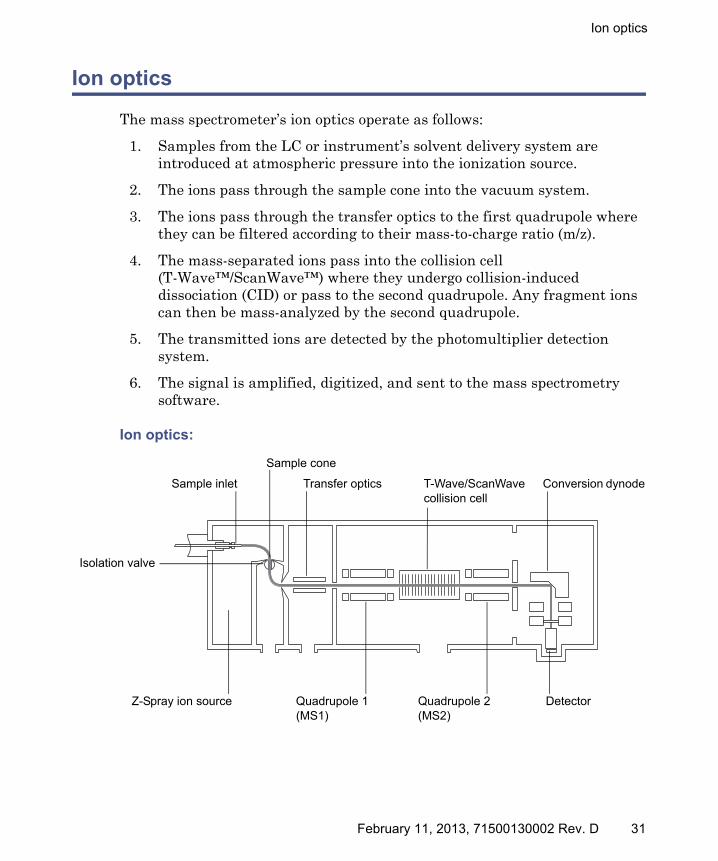
The mass spectrometer’s ion optics operate as follows:
1. Samples from the LC or instrument’s solvent delivery system are introduced at atmospheric pressure into the ionization source.
2. The ions pass through the sample cone into the vacuum system.
3. The ions pass through the transfer optics to the first quadrupole where they can be filtered according to their mass-to-charge ratio (m/z).
4. The mass-separated ions pass into the collision cell (T-Wave™/ScanWave™) where they undergo collision-induced dissociation (CID) or pass to the second quadrupole. Any fragment ions can then be mass-analyzed by the second quadrupole.
5. The transmitted ions are detected by the photomultiplier detection system.
6. The signal is amplified, digitized, and sent to the mass spectrometry software.
Ion optics:
Sample cone
Isolation valve
T-Wave/ScanWave collision cell
Z-Spray ion source Quadrupole 1 (MS1)
Quadrupole 2 (MS2)
Detector
Conversion dynodeSample inlet Transfer optics
February 11, 2013, 71500130002 Rev. D 31

1 Waters Xevo TQ MS Overview
MS operating modes
The following table shows the MS operating modes.
In MS mode, the instrument can acquire data at scan speeds up to 10,000 Da/s. Use this mode for instrument tuning and calibration before MS/MS analysis. See the mass spectrometer’s online Help for further information.
Use the selected ion recording (SIR) mode for quantitation when you cannot find a suitable fragment ion to perform a more specific multiple reaction monitoring (MRM) analysis. See “MS/MS operating modes” on page 33.
Note: In SIR and MRM modes, neither quadrupole is scanned, therefore no spectrum (intensity versus mass) is produced. The data obtained from SIR or MRM analyses derive from the chromatogram plot (specified mass intensity versus time).
MS operating modes:
Operating mode MS1 Collision cell MS2
MS Pass all masses Resolving (scanning)
SIR Pass all masses Resolving (static)
32 February 11, 2013, 71500130002 Rev. D

MS/MS operating modes
MS/MS operating modes
Note: In SIR and MRM modes, neither quadrupole is scanned, so no spectrum (intensity versus mass) is produced.
The following table shows the MS/MS operating modes.
MS/MS operating modes:
Operating mode MS1 Collision cell MS2
Product (daughter) ion spectrum
Static (at precursor mass)
Pass all masses Scanning
Precursor (parent) ion spectrum
Scanning Static (at product mass)
MRM Static (at precursor mass)
Static (at product mass)
Constant neutral loss spectrum
Scanning (synchronized with MS2)
Scanning (synchronized with MS1)
ScanWave daughter scan
Static (at precursor mass)
ScanWave enabled
Scanning (synchronized with collision cell)
February 11, 2013, 71500130002 Rev. D 33
1 Waters Xevo TQ MS Overview
Product (daughter) ion mode
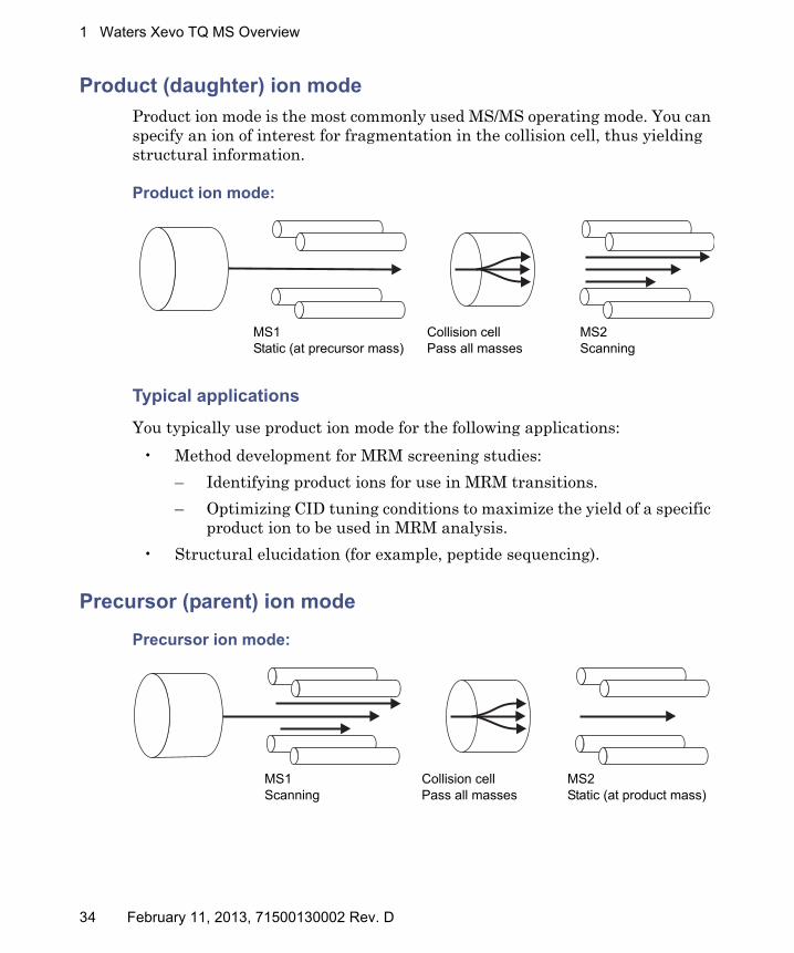
Product ion mode is the most commonly used MS/MS operating mode. You can specify an ion of interest for fragmentation in the collision cell, thus yielding structural information.
Product ion mode:
Typical applications
You typically use product ion mode for the following applications:
• Method development for MRM screening studies:
– Identifying product ions for use in MRM transitions.
– Optimizing CID tuning conditions to maximize the yield of a specific product ion to be used in MRM analysis.
• Structural elucidation (for example, peptide sequencing).
Precursor (parent) ion mode
Precursor ion mode:
MS1Static (at precursor mass)
MS2Scanning
Collision cellPass all masses
MS1Scanning
MS2Static (at product mass)
Collision cellPass all masses
34 February 11, 2013, 71500130002 Rev. D
MS/MS operating modes
Typical application
You typically use the precursor ion mode for structural elucidation—that is, to complement or confirm product scan data—by scanning for all the precursors of a common product ion.
Multiple reaction monitoring mode
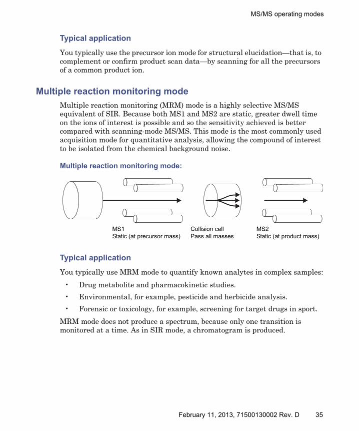
Multiple reaction monitoring (MRM) mode is a highly selective MS/MS equivalent of SIR. Because both MS1 and MS2 are static, greater dwell time on the ions of interest is possible and so the sensitivity achieved is better compared with scanning-mode MS/MS. This mode is the most commonly used acquisition mode for quantitative analysis, allowing the compound of interest to be isolated from the chemical background noise.
Multiple reaction monitoring mode:
Typical application
You typically use MRM mode to quantify known analytes in complex samples:
• Drug metabolite and pharmacokinetic studies.
• Environmental, for example, pesticide and herbicide analysis.
• Forensic or toxicology, for example, screening for target drugs in sport.
MRM mode does not produce a spectrum, because only one transition is monitored at a time. As in SIR mode, a chromatogram is produced.
MS1Static (at precursor mass)
MS2Static (at product mass)
Collision cellPass all masses
February 11, 2013, 71500130002 Rev. D 35

1 Waters Xevo TQ MS Overview
Constant neutral loss mode
Constant neutral loss mode detects the loss of a specific neutral fragment or functional group from an unspecified precursor(s).
The scans of MS1 and MS2 are synchronized. When MS1 transmits a specific precursor ion, MS2 “looks” to see whether that precursor loses a fragment of a certain mass. If it does, the loss registers at the detector.
In constant neutral loss mode, the spectrum shows the masses of all precursors that actually lost a fragment of a certain mass.
Constant neutral loss mode:
Typical application
You typically use constant neutral loss mode to screen mixtures for a specific class of compound that is characterized by a common fragmentation pathway, indicating the presence of compounds containing a common functional group.
MS1Scanning(synchronized with MS2)
Collision cellPass all masses
MS2Scanning(synchronized with MS1)
36 February 11, 2013, 71500130002 Rev. D
MS/MS operating modes
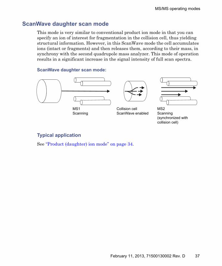
ScanWave daughter scan mode
This mode is very similar to conventional product ion mode in that you can specify an ion of interest for fragmentation in the collision cell, thus yielding structural information. However, in this ScanWave mode the cell accumulates ions (intact or fragments) and then releases them, according to their mass, in synchrony with the second quadrupole mass analyzer. This mode of operation results in a significant increase in the signal intensity of full scan spectra.
ScanWave daughter scan mode:
Typical application
See “Product (daughter) ion mode” on page 34.
MS1Scanning
Collision cellScanWave enabled
MS2Scanning(synchronized with collision cell)
February 11, 2013, 71500130002 Rev. D 37

1 Waters Xevo TQ MS Overview
Leak sensors
Leak sensors in the drip trays of the Xevo TQ MS continuously monitor the instrument for leaks. A leak sensor stops system flow when its optical sensor detects about 1.5 mL of accumulated leaked liquid in its surrounding reservoir. At the same time, the ACQUITY UPLC Console or UNIFI software displays an error message alerting you that a leak has developed.
See Waters ACQUITY UPLC Leak Sensor maintenance instructions for complete details.
Vacuum system
An external roughing (rotary vane) pump (a dry-pump option is available) and two internal turbomolecular pumps create the source vacuum. The turbomolecular pumps evacuate the analyzer and ion transfer region.
Vacuum leaks and electrical or vacuum pump failures cause vacuum loss, which protective interlocks guard against. The system monitors the turbomolecular pump speeds and continuously measures vacuum pressure with built-in Pirani and Penning gauges. The gauges also serve as switches, stopping operation when vacuum loss is sensed.
A vacuum isolation valve isolates the source from the mass analyzer, allowing routine source maintenance without venting.
38 February 11, 2013, 71500130002 Rev. D

Rear panel
Rear panel
The following figure shows the rear panel locations of the connectors used to operate the mass spectrometer with external devices.
Mass spectrometer rear panel:
TP03118
Auxiliary
10MB/100MB
Activity
External Connections 210 1
External Connections 110 1
LA N
EPC Com Port
Video Output
Service Bus12345678910 +-
Event In 1
ExternalConnections1
Not usedC
EInterlock
OUT
+-Event In 2
Not used
- IN IN
Com
N/C
N/O
Com
N/C
N/O
12345678910 +-AnalogueO
ut
ExternalConnections2
OUTG
as FailInterlock
Not used
- OUTOUT
+-Event O
ut 1
+-Event O
ut 2
OUT
Event inputs and outputs
Shielded Ethernet
Roughing pump relay switch
Source vacuum
Power connection
Source ventTurbo vacuum
Nitrogen inlet
Collision cell gas inlet
Pilot valve port
February 11, 2013, 71500130002 Rev. D 39

1 Waters Xevo TQ MS Overview
40 February 11, 2013, 71500130002 Rev. D
2 Preparing the Mass Spectrometer for Operation
This chapter describes how to start and shut down the mass spectrometer.
Contents
Topic Page
Starting the mass spectrometer ...................................................... 42
Preparing the IntelliStart Fluidics system..................................... 47
Rebooting the mass spectrometer ................................................... 49
Leaving the mass spectrometer ready for operation...................... 50
Emergency shutdown of the mass spectrometer ............................ 50
February 11, 2013, 71500130002 Rev. D 41

2 Preparing the Mass Spectrometer for Operation
Starting the mass spectrometer
This instrument is compatible with the ACQUITY UPLC system; if you are not using an ACQUITY UPLC system, refer to the documentation relevant to the system you are using. See “Non-ACQUITY devices for use with the Xevo TQ MS” on page 25.
Starting the mass spectrometer entails powering-on the workstation, logging in, powering-on the mass spectrometer and all other instruments, and starting the MassLynx or UNIFI software.
Requirement: You must power-on and log in to the workstation first to ensure that it obtains the IP addresses of the system instruments.
See the mass spectrometer’s online Help for details on MassLynx, IntelliStart, and UNIFI software.
To start the mass spectrometer:
1. On the rear panel, ensure the nitrogen supply is connected to the instrument’s nitrogen inlet connection (see the figure on page 39).
Requirement: The nitrogen must be dry and oil-free, with a purity of at least 95%. Regulate the supply at 600 to 690 kPa (6.0 to 6.9 bar, 90 to 100 psi).
2. Ensure that the collision gas supply is connected to the instrument’s collision cell gas inlet.
Requirement: The collision gas is argon; it must be dry and of high purity (99.9%). Regulate the supply at 50 kPa (0.5 bar, 7 psi).
3. Power-on the workstation, and log in before powering-on the other instruments.
Caution: To avoid causing severe damage to the instrument, use only compatible solvents. For more details, refer to the following sources:• Appendix B, “Materials of Construction and Compliant Solvents”,
for mass spectrometer solvent information.• Appendix C of the ACQUITY UPLC System Operator’s Guide for
solvent compatibility with ACQUITY devices.
Warning: To avoid ignition of flammable solvents, never let the nitrogen supply pressure fall below 690 kPa (6.9 bar, 100 psi).
42 February 11, 2013, 71500130002 Rev. D

Starting the mass spectrometer
4. Press the power switch on the top, left-hand side of the mass spectrometer and ACQUITY instruments.
Result: Each system instrument “beeps” and runs a series of startup tests.
5. Allow 3 minutes for the embedded PC to initialize. An audible alert sounds when the PC is ready.
Tip: The power and operate LEDs change as follows:
• During initialization, the binary solvent manager’s and sample manager’s status LED flashes green.
• After the instruments are successfully powered-on, all power LEDs show steady green. The binary solvent manager’s flow LED, the sample manager’s run LED, and the mass spectrometer’s Operate LED remain off.
6. Start the MassLynx or UNIFI software, and monitor the Instrument Console software for messages and LED indications.
7. To evacuate (pump down) the mass spectrometer, follow the procedure below for MassLynx software or UNIFI software.
MassLynx software:
a. Click IntelliStart in the MassLynx main window’s lower left-hand corner.
Result: The mass spectrometer’s console appears. The mass spectrometer is in Standby mode.
b. Click Control > Pump, to start the roughing pump.
Note: The Operate LED remains off.
c. Wait a minimum of 2 hours for the instrument to be fully pumped down (evacuated).
Tip: In the Instrument Console, the System Ready indicator shows green when the instrument is fully pumped down (evacuated).
February 11, 2013, 71500130002 Rev. D 43

2 Preparing the Mass Spectrometer for Operation
d. Click Resolve or Operate .
Result: When the mass spectrometer is in good operating condition, IntelliStart software displays “Ready” in the Instrument Console.
Tip: If clicking Resolve fails to put the instrument into Operate mode, IntelliStart software displays corrective actions in the Instrument Console.
UNIFI software:
a. From the Xevo TQ MS console, in the Maintain pane, click Vacuum.
b. On the status page, click Pump.
Tip: After a 20-second delay, during which the turbopump is starting, the roughing pump starts. The Instrument System pane shows that the instrument is in Standby mode, and the Operate LED remains off.
c. Wait a minimum of 2 hours for the instrument to be fully pumped down (evacuated).
Tip: In the Instrument Summary pane, the Status indicator shows green when the instrument is fully pumped down (evacuated).
d. Click Instrument Operate Mode .
Result: When the mass spectrometer is in good operating condition, UNIFI software displays status “Running” in the Instrument Summary pane.
Tip: If clicking Instrument Operate Mode fails to put the instrument into Operate mode, UNIFI software displays corrective actions.
44 February 11, 2013, 71500130002 Rev. D
Starting the mass spectrometer
Verifying the instrument’s state of readiness
When the mass spectrometer is in good operating condition, the power and Operate LEDs show constant green. You can view any error messages in IntelliStart software (MassLynx), or UNIFI software.
Monitoring the mass spectrometer LEDs
Light-emitting diodes on the mass spectrometer indicate its operational status.
Power LED
The power LED, to the top, left-hand side of the mass spectrometer’s front panel, indicates when the mass spectrometer is powered-on or powered-off.
Operate LED
The Operate LED, on the right-hand side of the power LED, indicates the operating condition.
See the mass spectrometer’s online Help topic “Monitoring the mass spectrometer LEDs” for details on the Operate LED indications.
Tuning and calibration information
You must tune and calibrate the mass spectrometer prior to use. You can perform these tasks using IntelliStart (MassLynx software) or UNIFI software.
For further instruction, see the mass spectrometer’s online Help.
February 11, 2013, 71500130002 Rev. D 45
2 Preparing the Mass Spectrometer for Operation
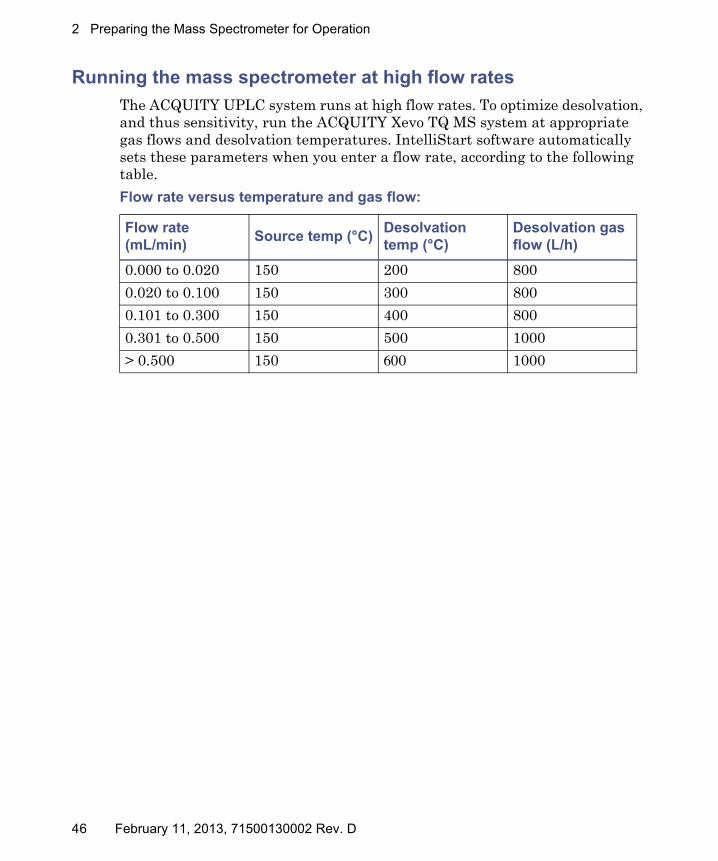
Running the mass spectrometer at high flow rates
The ACQUITY UPLC system runs at high flow rates. To optimize desolvation, and thus sensitivity, run the ACQUITY Xevo TQ MS system at appropriate gas flows and desolvation temperatures. IntelliStart software automatically sets these parameters when you enter a flow rate, according to the following table.
Flow rate versus temperature and gas flow:
Flow rate (mL/min)
Source temp (°C)Desolvation temp (°C)
Desolvation gas flow (L/h)
0.000 to 0.020 150 200 800
0.020 to 0.100 150 300 800
0.101 to 0.300 150 400 800
0.301 to 0.500 150 500 1000
> 0.500 150 600 1000
46 February 11, 2013, 71500130002 Rev. D

Preparing the IntelliStart Fluidics system
Preparing the IntelliStart Fluidics system
For additional information, see “Connecting the liquid waste line” on page 234.
Installing the reservoir bottles
Use standard reservoir bottles (30 mL) for instrument setup and calibration. Use the Low-volume Adaptor Kit (included) to infuse smaller volumes. The low-volume vials have a volume of 1.5 mL.
Required materials
Chemical-resistant, powder-free gloves
To install the reservoir bottles:
1. Remove the reservoir bottle caps.
2. Screw the reservoir bottles onto the mass spectrometer as shown below.
Caution: To avoid accidental spillage damaging the instrument, do not store large volume solvent reservoirs on top of the instrument.
Warning: To avoid becoming contaminated with biohazards or toxic compounds, always wear chemical-resistant, powder-free gloves while performing this procedure.
Reservoir bottle
February 11, 2013, 71500130002 Rev. D 47
2 Preparing the Mass Spectrometer for Operation
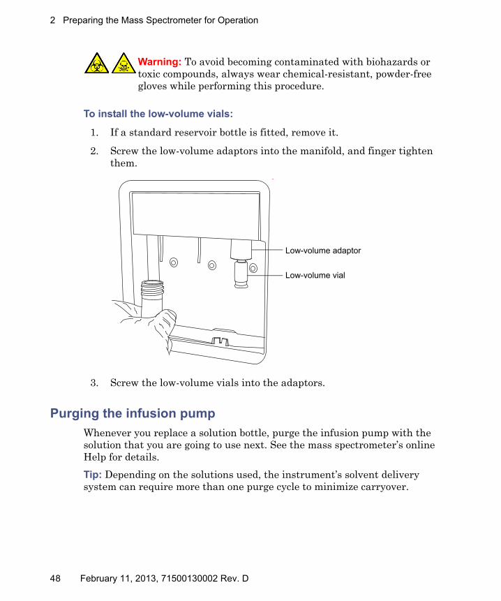
To install the low-volume vials:
1. If a standard reservoir bottle is fitted, remove it.
2. Screw the low-volume adaptors into the manifold, and finger tighten them.
3. Screw the low-volume vials into the adaptors.
Purging the infusion pump
Whenever you replace a solution bottle, purge the infusion pump with the solution that you are going to use next. See the mass spectrometer’s online Help for details.
Tip: Depending on the solutions used, the instrument’s solvent delivery system can require more than one purge cycle to minimize carryover.
Warning: To avoid becoming contaminated with biohazards or toxic compounds, always wear chemical-resistant, powder-free gloves while performing this procedure.
Low-volume vial
Low-volume adaptor
48 February 11, 2013, 71500130002 Rev. D
Rebooting the mass spectrometer
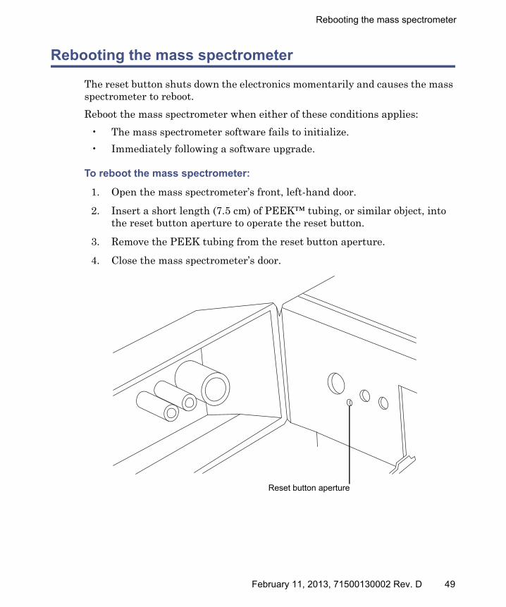
Rebooting the mass spectrometer
The reset button shuts down the electronics momentarily and causes the mass spectrometer to reboot.
Reboot the mass spectrometer when either of these conditions applies:
• The mass spectrometer software fails to initialize.
• Immediately following a software upgrade.
To reboot the mass spectrometer:
1. Open the mass spectrometer’s front, left-hand door.
2. Insert a short length (7.5 cm) of PEEK™ tubing, or similar object, into the reset button aperture to operate the reset button.
3. Remove the PEEK tubing from the reset button aperture.
4. Close the mass spectrometer’s door.
Reset button aperture
February 11, 2013, 71500130002 Rev. D 49

2 Preparing the Mass Spectrometer for Operation
Leaving the mass spectrometer ready for operation
Leave the mass spectrometer in Operate mode except in the following cases:
• When performing routine maintenance
• When changing the source
• When leaving the mass spectrometer unused for a long period
In these instances, put the mass spectrometer in Standby mode, see the online Help for details.
Emergency shutdown of the mass spectrometer
To shut down the mass spectrometer in an emergency:
1. Operate the power button on the front of the mass spectrometer.
2. Disconnect the power cable from the back of the mass spectrometer.
Warning: To avoid electric shock, isolate the instrument observing the procedure outlined below. The instrument’s power switch does not isolate it from the main power supply.
Caution: To avoid losing data, reboot the instrument as described on page 49.
50 February 11, 2013, 71500130002 Rev. D
3 Changing the Mode of Operation
This chapter describes how to prepare the mass spectrometer for the
following modes of operation:
• ESI (electrospray ionization)
• ESCi (combined electrospray and atmospheric pressure chemical ionization)
• APCI (atmospheric pressure chemical ionization)
• Combined Atmospheric Pressure Photoionization (APPI)/APCI
• NanoFlow ESI.
Note: Available source options can vary depending on the software used to operate the Xevo TQ MS. Refer to the MassLynx or UNIFI online Help for more information about supported sources.
Contents:
Topic Page
ESI mode .......................................................................................... 52
ESCi mode ........................................................................................ 57
APCI mode........................................................................................ 57
Combined APPI/APCI source .......................................................... 61
NanoFlow ESI source....................................................................... 69
February 11, 2013, 71500130002 Rev. D 51
3 Changing the Mode of Operation
ESI mode
To run ESI, you must fit the ESI probe to the ESI/APCI/ESCi source enclosure. The following sections explain how to install and remove the ESI probe.
Installing the ESI probe
Required material
Chemical-resistant, powder-free gloves
To install the ESI probe:
1. Prepare the instrument for working on the source (see “Preparing the instrument for working on the source” on page 85).
2. Remove the protective sleeve, if fitted, from the ESI probe tip.
Warning: To avoid personal contamination with biohazards or toxic materials, and to avoid spreading contamination to uncontaminated surfaces, wear clean, chemical-resistant, powder-free gloves while performing this procedure. The LC system connections, ESI probe, and source can be contaminated.
Warning: To avoid electric shock, ensure that the instrument is prepared for working on the source before commencing this procedure.
Warning: To avoid puncture wounds, handle the ESI probe with care; the probe tip is sharp.
52 February 11, 2013, 71500130002 Rev. D
ESI mode
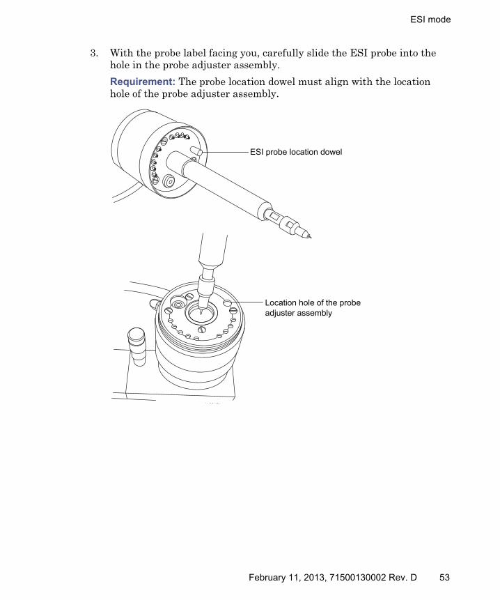
3. With the probe label facing you, carefully slide the ESI probe into the hole in the probe adjuster assembly.
Requirement: The probe location dowel must align with the location hole of the probe adjuster assembly.
TP03129
Location hole of the probe adjuster assembly
ESI probe location dowel
February 11, 2013, 71500130002 Rev. D 53

3 Changing the Mode of Operation
ESI probe, mounted on the source enclosure:
4. Tighten the probe locking ring to secure the probe in place.
5. Connect the ESI probe’s cable to the high voltage connector.
6. Open the access door to the fluidics valve (see the figure on page 24).
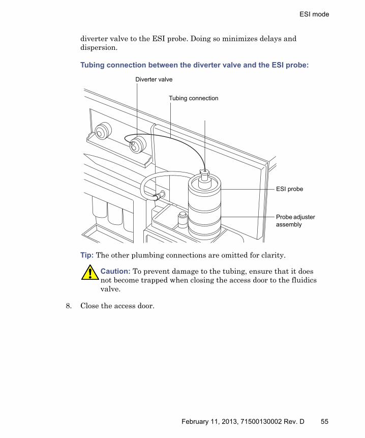
7. Using tubing greater than or equal to 0.004-inch ID, connect port 2 (the top port) of the diverter valve to the ESI probe.
Recommendation: To reduce peak broadening, use 0.004-inch ID tubing for sample flow rates ≤ 1.2 mL/min; use 0.005-inch ID tubing for sample flow rates > 1.2 mL/min.
Requirement: If you are replacing the tubing supplied with the instrument, you must minimize the length of the tube connecting the
Caution: To avoid nitrogen leakage, fully tighten the probe locking ring.
Warning: To avoid electric shock, do not use stainless steel tubing to connect the diverter valve to the ESI probe; use the PEEK tubing supplied with the instrument.
TP03128
ESI probe cable
ESI probe
Vernier probe adjuster
Probe locking ring
Source window
High voltage connector
Source enclosure release
Vertical probe adjuster
54 February 11, 2013, 71500130002 Rev. D
ESI mode
diverter valve to the ESI probe. Doing so minimizes delays and dispersion.
Tubing connection between the diverter valve and the ESI probe:
Tip: The other plumbing connections are omitted for clarity.
8. Close the access door.
Caution: To prevent damage to the tubing, ensure that it does not become trapped when closing the access door to the fluidics valve.
ESI probe
Diverter valve
Tubing connection
Probe adjuster assembly
February 11, 2013, 71500130002 Rev. D 55
3 Changing the Mode of Operation
Removing the ESI probe
Required material
Chemical-resistant, powder-free gloves
To remove the ESI probe:
1. Prepare the instrument for working on the source (see “Preparing the instrument for working on the source” on page 85).
2. Disconnect the tubing from the ESI probe.
3. Disconnect the ESI probe’s cable from the high voltage connector.
4. Unscrew the probe locking ring.
5. Carefully remove the ESI probe from the probe adjuster assembly.
6. If available, fit the protective sleeve to the ESI probe tip.
Warning: To avoid personal contamination with biohazards or toxic materials, and to avoid spreading contamination to uncontaminated surfaces, wear clean, chemical-resistant, powder-free gloves while performing this procedure. The LC system connections, ESI probe, and source can be contaminated.
Warning: To avoid electric shock, ensure that the instrument is prepared for working on the source before commencing this procedure.
Warning: To avoid puncture wounds, handle the probe with care; the ESI probe tip is sharp.
56 February 11, 2013, 71500130002 Rev. D

ESCi mode
ESCi mode
To run ESCi, you must fit an ESI probe and corona pin to the ESI/APCI/ESCi source enclosure.
See “Installing the ESI probe” on page 52, “Installing the corona pin in the source” on page 90, and “Combined electrospray ionization and atmospheric pressure chemical ionization (ESCi)” on page 27.
Optimizing the ESI probe for ESCi operation
See the mass spectrometer’s online Help for details on how to optimize the ESI probe for ESCi operation.
APCI mode
APCI mode, an option for the mass spectrometer, produces singly-charged protonated or deprotonated molecules for a broad range of nonvolatile analytes.
The APCI interface consists of the ESI/APCI/ESCi enclosure fitted with a corona pin and an APCI probe. Mobile phase from the LC column enters the probe, where it is pneumatically converted to an aerosol, rapidly heated, and vaporized or gasified at the probe tip.
APCI mode:
Hot gas from the APCI probe passes between the sample cone and the corona pin, which is typically operated with a discharge current of 5 µA. Mobile phase molecules rapidly react with ions generated by the corona discharge to produce stable reagent ions. Analyte molecules introduced into the mobile phase react with the reagent ions at atmospheric pressure and typically become protonated (in the positive ion mode) or deprotonated (in the negative ion mode). The sample and reagent ions then pass through the sample cone and into the mass spectrometer.
APCI probe
Sample coneCorona pin
February 11, 2013, 71500130002 Rev. D 57

3 Changing the Mode of Operation
Installing the APCI probe
Required material: Chemical-resistant, powder-free gloves
To install the APCI probe:
1. Prepare the instrument for working on the source (see “Preparing the instrument for working on the source” on page 85).
2. With the probe label facing towards you, carefully slide the APCI probe into the hole in the probe adjuster assembly, ensuring that the probe location dowel aligns with the probe adjuster assembly location hole.
Warning: To avoid personal contamination with biohazards or toxic materials, and to avoid spreading contamination to uncontaminated surfaces, wear clean, chemical-resistant, powder-free gloves while performing this procedure. The LC system connections, APCI probe, and source can be contaminated.
Warning: To avoid electric shock, ensure that the instrument is prepared for working on the source before commencing this procedure.
TP03129
APCI probe location dowel
Probe adjuster assembly location hole
58 February 11, 2013, 71500130002 Rev. D
APCI mode
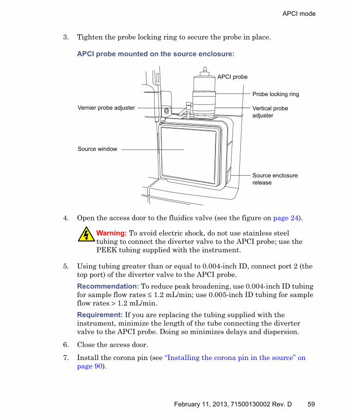
3. Tighten the probe locking ring to secure the probe in place.
APCI probe mounted on the source enclosure:
4. Open the access door to the fluidics valve (see the figure on page 24).
5. Using tubing greater than or equal to 0.004-inch ID, connect port 2 (the top port) of the diverter valve to the APCI probe.
Recommendation: To reduce peak broadening, use 0.004-inch ID tubing for sample flow rates ≤ 1.2 mL/min; use 0.005-inch ID tubing for sample flow rates > 1.2 mL/min.
Requirement: If you are replacing the tubing supplied with the instrument, minimize the length of the tube connecting the diverter valve to the APCI probe. Doing so minimizes delays and dispersion.
6. Close the access door.
7. Install the corona pin (see “Installing the corona pin in the source” on page 90).
Warning: To avoid electric shock, do not use stainless steel tubing to connect the diverter valve to the APCI probe; use the PEEK tubing supplied with the instrument.
TP03128
APCI probe
Vernier probe adjuster
Source enclosure release
Probe locking ring
Source window
Vertical probe adjuster
February 11, 2013, 71500130002 Rev. D 59

3 Changing the Mode of Operation
Removing the APCI probe
Required material
Chemical-resistant, powder-free gloves
To remove the APCI probe:
1. Prepare the instrument for working on the source (see “Preparing the instrument for working on the source” on page 85).
2. Remove the corona pin (see “Removing the corona pin from the source” on page 93).
3. Disconnect the diverter valve tubing from the APCI probe.
4. Unscrew the probe locking ring.
5. Carefully remove the probe from the probe adjuster assembly.
Warning: To avoid personal contamination with biohazards or toxic materials, and to avoid spreading contamination to uncontaminated surfaces, wear clean, chemical-resistant, powder-free gloves while performing this procedure. The LC system connections, APCI probe, and source can be contaminated.
Warning: To avoid electric shock, ensure that the instrument is prepared for working on the source before commencing this procedure.
60 February 11, 2013, 71500130002 Rev. D

Combined APPI/APCI source
Combined APPI/APCI source
This optional, replacement source-enclosure can be operated as APPI, APCI or dual-mode APPI/APCI. Where, dual-mode APPI/APCI performs rapid switching between ionization modes.
APPI operation
In atmospheric pressure photoionization (APPI) mode, the source is fitted with an APCI probe, and the APPI lamp drive assembly is advanced into the source.
APPI mode:
The APCI probe introduces vaporized sample into the source where photons generated by an ultra-violet (UV) lamp (mounted in the APPI lamp drive assembly) produce sample ions. Direct photoionization of a sample molecule occurs when the photon energy exceeds the ionization potential of the sample molecule.
A repeller electrode (mounted on the APPI lamp drive assembly) deflects and focuses the sample ions towards the sample cone.
APCI probe
Sample molecules
APPI lamp drive assembly
Repeller electrodeUV lamp
Sample ions
Sample cone
Photons from the UV lamp
February 11, 2013, 71500130002 Rev. D 61

3 Changing the Mode of Operation
APCI operation
Atmospheric pressure chemical ionization (APCI) produces singly-charged protonated or deprotonated molecules for a large range of nonvolatile analytes. In APCI mode, the source is fitted with an APCI corona pin. Unused, the APPI lamp drive assembly is retracted from the source.
APCI mode:
The APCI probe introduces vaporized sample into the source. The sample passes between the sample cone and the corona pin, which typically operates with a discharge current of 5 µA. The corona discharge generates ions that react with the mobile phase molecules to produce stable reagent ions. Analyte molecules in the mobile phase react with the reagent ions at atmospheric pressure and become protonated (in the positive ion mode) or deprotonated (in the negative ion mode). The sample and reagent ions pass through the sample cone.
APCI probe
Retracted APPI lamp drive assembly
Sample cone
APCI corona pin
62 February 11, 2013, 71500130002 Rev. D

Combined APPI/APCI source
Dual-mode operation
Dual-mode operation enables rapid switching between APPI and APCI ionization modes and allows high-throughput operations (for example, for sample screening).
You replace the standard corona pin with a specially shaped APPI/APCI corona pin, so that the APPI lamp holder can be advanced into the source for dual operation.
When the source is configured for dual operation in APCI mode, current is applied to the corona pin, but the repeller electrode is inactive.
Dual operation in APCI mode:
When the source is configured for dual operation in APPI mode, the corona pin is inactive, and a voltage is applied to the repeller electrode.
Dual operation in APPI mode:
Sample cone
APCI probe
Photons from the UV lamp
Repeller electrode inactive
Corona pin with current applied
Sample cone
APCI probe
Photons from the UV lamp
Repeller electrode with voltage applied
Corona pin inactive
February 11, 2013, 71500130002 Rev. D 63
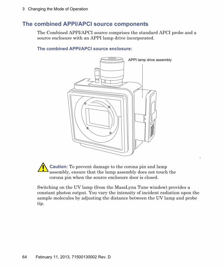
3 Changing the Mode of Operation
The combined APPI/APCI source components
The Combined APPI/APCI source comprises the standard APCI probe and a source enclosure with an APPI lamp drive incorporated.
The combined APPI/APCI source enclosure:
.
Switching on the UV lamp (from the MassLynx Tune window) provides a constant photon output. You vary the intensity of incident radiation upon the sample molecules by adjusting the distance between the UV lamp and probe tip.
Caution: To prevent damage to the corona pin and lamp assembly, ensure that the lamp assembly does not touch the corona pin when the source enclosure door is closed.
XMS0001
APPI lamp drive assembly
64 February 11, 2013, 71500130002 Rev. D

Combined APPI/APCI source
APPI lamp drive assembly inside the source enclosure:
TP03201
APPI lamp drive assembly
Source enclosure
UV lamp and repeller electrode
APCI probe
February 11, 2013, 71500130002 Rev. D 65

3 Changing the Mode of Operation
Installing the Combined APPI/APCI Source software
If the Combined APPI/APCI Source is not installed on the instrument, insert the Software Upgrade CD-ROM into the MassLynx workstation CD drive, and follow the on-screen instructions.
Tip: If this software upgrade is not installed, the APPI options will not be available in the Tune window’s Ion Mode menu.
Required materials
Chemical-resistant, powder-free gloves
To install the combined APPI/APCI source:
1. Prepare the instrument for working on the source (see “Preparing the instrument for working on the source” on page 85).
2. Remove the probe from the currently installed source.
• If you are removing an ESI probe, see “Removing the ESI probe” on page 56.
• If you are removing an APCI probe, see “Removing the APCI probe” on page 60.
3. Remove the existing source enclosure (see “Removing the source enclosure from the instrument” on page 87).
4. Install the combined APPI/APCI source-enclosure (see “Fitting the source enclosure to the instrument” on page 89).
5. Install the specially shaped corona pin (see “Installing the corona pin in the source” on page 90).
Warning: To avoid personal contamination with biohazards or toxic materials, and to avoid spreading contamination to uncontaminated surfaces, wear clean, chemical-resistant, powder-free gloves while performing this procedure. The source components can be contaminated.
Warning: To avoid electric shock, ensure that the instrument is suitably prepared before commencing this procedure.
Warning: To avoid burn injuries, take great care while working with the probe and source; these components can be hot.
66 February 11, 2013, 71500130002 Rev. D

Combined APPI/APCI source
6. Connect the APPI drive cable, to the instrument front panel.
7. Connect the HT cable, to the instrument front panel.
8. Close the instrument’s front access door.
9. Install the APCI probe to the source and ensure that it is working correctly (see “Installing the APCI probe” on page 58).
Tip: An automatic pressure test is performed each time the source-enclosure is closed and when the instrument starts.
Caution: To prevent damage to the corona pin and lamp assembly, ensure that the lamp assembly does not touch the corona pin when the source enclosure door is closed.
February 11, 2013, 71500130002 Rev. D 67
3 Changing the Mode of Operation
Removing the APCI probe and APPI source enclosure
Required materials
Chemical-resistant, powder-free gloves
To remove the combined APPI/APCI source:
1. Prepare the instrument for working on the source (see “Preparing the instrument for working on the source” on page 85).
2. Remove the APCI probe (see “Removing the APCI probe” on page 60).
3. Disconnect the HT cable, from the instrument front panel.
4. Disconnect the APPI drive cable, from the instrument front panel.
5. Remove the source enclosure (see “Removing the source enclosure from the instrument” on page 87).
6. Remove the corona pin (see “Removing the corona pin from the source” on page 93).
7. Fit the blanking plug to the pin’s mounting contact.
Warning: To avoid personal contamination with biohazards or toxic materials, and to avoid spreading contamination to uncontaminated surfaces, wear clean, chemical-resistant, powder-free gloves while performing this procedure. The source components can be contaminated.
Warning: To avoid electric shock, ensure that the instrument is suitably prepared before commencing this procedure.
Warning: To avoid burn injuries, take great care while working with the probe and source; these components can be hot.
68 February 11, 2013, 71500130002 Rev. D

NanoFlow ESI source
NanoFlow ESI source
The NanoFlow source enclosure comprises the NanoFlow stage (for x-, y-, z-axis adjustment), the sprayer-enclosure, and a microscope camera.
NanoFlow source, stage and microscope camera:
A sprayer is mounted on an X, Y, Z stage (three-axis manipulator) which slides on a pair of guide rails that allow its withdrawal from the source-enclosure for maintenance and changes.
A light within the source provides illumination for the spray, which you can observe using the video camera mounted on the corner of the source housing.
The low flow rates involved with operating the NanoFlow source prohibit its use with the instrument’s solvent delivery system.
XMS0022
Microscope camera
Sprayer enclosure
X, Y, Z stage
February 11, 2013, 71500130002 Rev. D 69

3 Changing the Mode of Operation
Installing the NanoFlow source
Required materials
• Chemical-resistant, powder-free gloves
To install the NanoFlow source:
1. Prepare the instrument for working on the source (see “Preparing the instrument for working on the source” on page 85).
2. Remove the probe from the currently installed source.
• If you are removing an ESI probe, see “Removing the ESI probe” on page 56.
• If you are removing an APCI probe, see “Removing the APCI probe” on page 60.
3. Remove the existing source enclosure (see “Removing the source enclosure from the instrument” on page 87).
Warning: To avoid personal contamination with biohazards or toxic materials, and to avoid spreading contamination to uncontaminated surfaces, wear clean, chemical-resistant, powder-free gloves while performing this procedure. The source components can be contaminated.
Warning: To avoid electric shock, ensure that the instrument is suitably prepared before commencing this procedure.
Warning: To avoid burn injuries, ensure that the source heater is turned off and the ion block is cool before opening the source. The ion block, which can be hot, is exposed when you fit the NanoFlow source.
Warning: To avoid burn injuries, take great care while working with the probe and source; these components can be hot.
70 February 11, 2013, 71500130002 Rev. D

NanoFlow ESI source
4. On the NanoFlow source, release the stage retaining-screw, pull the stop screw and slide the stage fully out of the enclosure.
5. Using both hands, fit the NanoFlow source enclosure to the two supporting studs on the source adaptor housing.
6. Close the source enclosure door.
7. Connect a 1/16 inch PTFE tube between the mass-flow controller output (mounted beneath the stage on the front of the NanoFlow source) and your sprayer.
Tip: For details regarding how to fit each sprayer, see the corresponding reference:
• Waters Universal NanoFlow Sprayer Installation and Maintenance Guide (part number 71500110107)
• “Fitting a borosilicate glass capillary (nanovial)” on page 73
• Capillary Electrophoresis/ Capillary Electrochromatography Sprayer User's Guide (part number 6666522)
Caution: To prevent the sprayer colliding with the cone and breaking, always retract the stage before installing the source enclosure or closing the door.
Stop screwRetaining screw
February 11, 2013, 71500130002 Rev. D 71
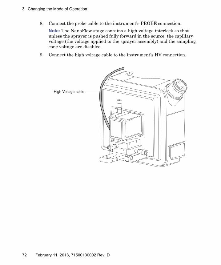
3 Changing the Mode of Operation
8. Connect the probe cable to the instrument’s PROBE connection.
Note: The NanoFlow stage contains a high voltage interlock so that unless the sprayer is pushed fully forward in the source, the capillary voltage (the voltage applied to the sprayer assembly) and the sampling cone voltage are disabled.
9. Connect the high voltage cable to the instrument’s HV connection.
XMS0023
High Voltage cable
72 February 11, 2013, 71500130002 Rev. D

NanoFlow ESI source
Fitting a borosilicate glass capillary (nanovial)
Required materials
• Chemical-resistant, powder-free gloves
• Needle-nose pliers
To fit a borosilicate glass capillary (nanovial):
1. Loosen the stage retaining screw.
2. Pull the stop screw to release the stage.
3. Slide the stage out of the NanoFlow source enclosure and remove the magnetic cover.
4. Unscrew the retaining screw, and lift the sprayer from the stage.
Warning: To avoid lacerations, puncture injuries, and possible contamination with biohazardous and toxic samples, do not touch the sharp end of the capillary.
Caution: To avoid damaging capillaries, take great care when handling them. Capillaries are extremely fragile; always hold their blunt end, never the sharp end, which can easily be damaged.
Warning: To avoid electric shock, ensure that the NanoFlow stage is fully retracted from the source before beginning this procedure.
February 11, 2013, 71500130002 Rev. D 73
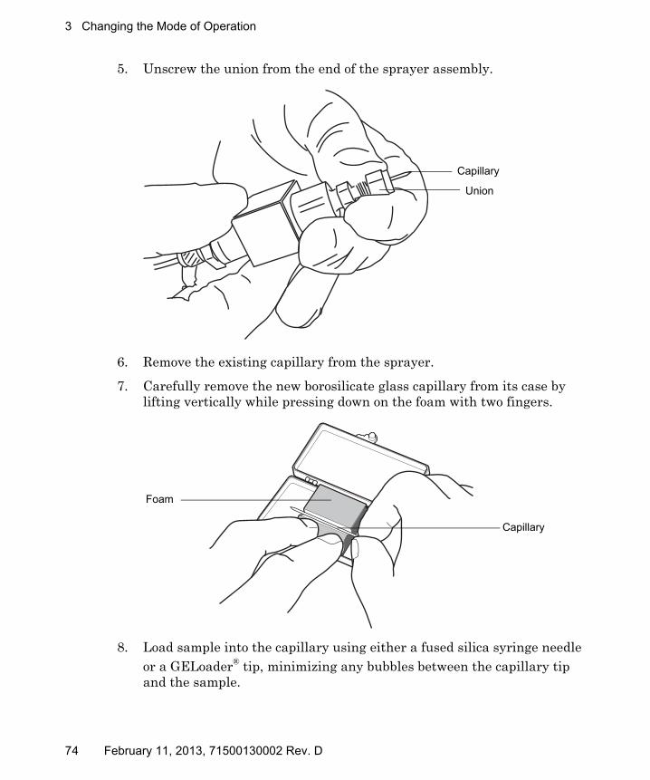
3 Changing the Mode of Operation
5. Unscrew the union from the end of the sprayer assembly.
6. Remove the existing capillary from the sprayer.
7. Carefully remove the new borosilicate glass capillary from its case by lifting vertically while pressing down on the foam with two fingers.
8. Load sample into the capillary using either a fused silica syringe needle or a GELoader® tip, minimizing any bubbles between the capillary tip and the sample.
Capillary
Union
Foam
Capillary
74 February 11, 2013, 71500130002 Rev. D
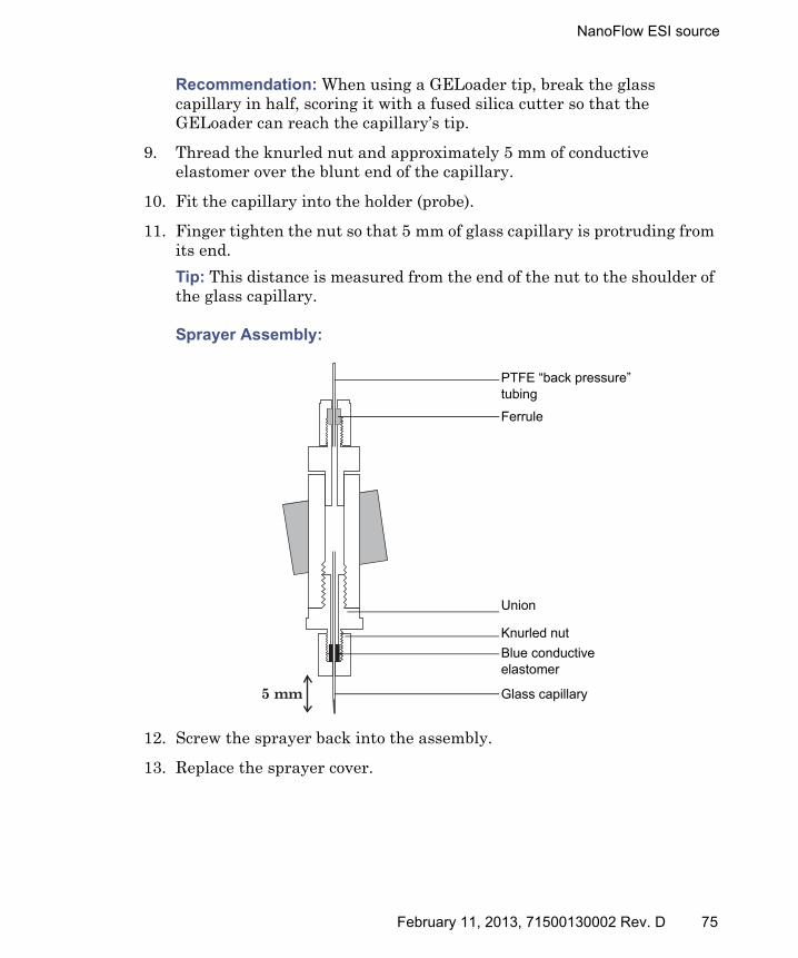
NanoFlow ESI source
Recommendation: When using a GELoader tip, break the glass capillary in half, scoring it with a fused silica cutter so that the GELoader can reach the capillary’s tip.
9. Thread the knurled nut and approximately 5 mm of conductive elastomer over the blunt end of the capillary.
10. Fit the capillary into the holder (probe).
11. Finger tighten the nut so that 5 mm of glass capillary is protruding from its end.
Tip: This distance is measured from the end of the nut to the shoulder of the glass capillary.
Sprayer Assembly:
12. Screw the sprayer back into the assembly.
13. Replace the sprayer cover.
5 mm
PTFE “back pressure” tubing
Ferrule
Union
Knurled nut
Blue conductive elastomer
Glass capillary
February 11, 2013, 71500130002 Rev. D 75

3 Changing the Mode of Operation
14. On the MassLynx MS Tune window, ensure that the Capillary (kV) parameter on the ES+/- Source tab is set to 0.
15. Carefully push the stage back into the NanoFlow source enclosure, using the stop and handle.
Caution: To avoid damage to the capillary tip, adjust the sprayer tip position before you push the sprayer inside the NanoFlow source enclosure. Ensure that the capillary tip does not collide with the cone or the side of the source.
76 February 11, 2013, 71500130002 Rev. D
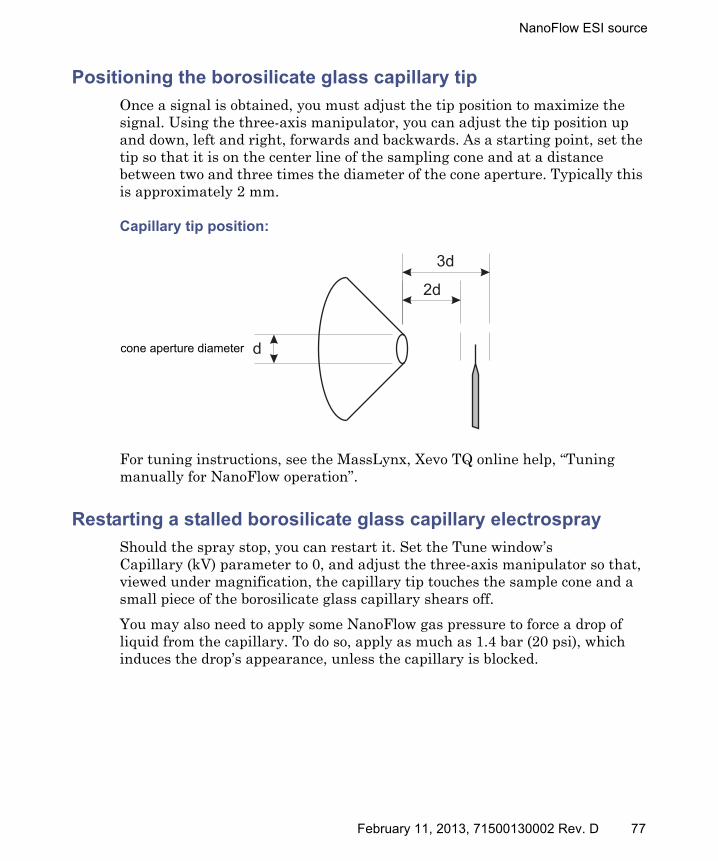
NanoFlow ESI source
Positioning the borosilicate glass capillary tip
Once a signal is obtained, you must adjust the tip position to maximize the signal. Using the three-axis manipulator, you can adjust the tip position up and down, left and right, forwards and backwards. As a starting point, set the tip so that it is on the center line of the sampling cone and at a distance between two and three times the diameter of the cone aperture. Typically this is approximately 2 mm.
Capillary tip position:
For tuning instructions, see the MassLynx, Xevo TQ online help, “Tuning manually for NanoFlow operation”.
Restarting a stalled borosilicate glass capillary electrospray
Should the spray stop, you can restart it. Set the Tune window’s Capillary (kV) parameter to 0, and adjust the three-axis manipulator so that, viewed under magnification, the capillary tip touches the sample cone and a small piece of the borosilicate glass capillary shears off.
You may also need to apply some NanoFlow gas pressure to force a drop of liquid from the capillary. To do so, apply as much as 1.4 bar (20 psi), which induces the drop’s appearance, unless the capillary is blocked.
d
2d
3d
cone aperture diameter
February 11, 2013, 71500130002 Rev. D 77

3 Changing the Mode of Operation
78 February 11, 2013, 71500130002 Rev. D

4 Maintenance Procedures
This chapter provides the maintenance guidelines and procedures necessary to maintain the instrument’s performance.
Keep to a maintenance schedule, and perform maintenance as required and described in this chapter.
Contents
Topic Page
Maintenance schedule ..................................................................... 81
Spare parts ....................................................................................... 82
Troubleshooting with Connections INSIGHT ................................ 83
Safety and handling......................................................................... 84
Preparing the instrument for working on the source .................... 85
Removing and refitting the source enclosure ................................. 87
Installing and removing the corona pin.......................................... 90
Operating the source isolation valve............................................... 94
Removing O-rings and seals ............................................................ 97
Cleaning the instrument case ......................................................... 98
Emptying the nitrogen exhaust trap bottle .................................... 98
Inspecting the Varian roughing pump oil level.............................. 101
Adding oil to the Varian roughing pump........................................ 102
Replacing the Varian roughing pump oil and oil mist filter.......... 104
Cleaning the source components..................................................... 110
Cleaning the sampling cone assembly ............................................ 111
Cleaning the extraction cone ........................................................... 120
Cleaning the ion block assembly ..................................................... 128
Cleaning the source hexapole assembly ......................................... 140
Replacing the ESI probe tip and gasket ......................................... 146
Replacing the ESI probe sample capillary...................................... 150
February 11, 2013, 71500130002 Rev. D 79

4 Maintenance Procedures
Cleaning the APCI probe tip ........................................................... 158
Replacing the APCI probe sample capillary ................................... 159
Cleaning or replacing the corona pin .............................................. 165
Replacing the APCI probe heater.................................................... 166
Replacing the ion block source heater............................................. 170
Replacing the source assembly seals .............................................. 174
Replacing the air filter..................................................................... 179
APPI/APCI source—changing the UV lamp bulb........................... 181
APPI/APCI source—Cleaning the lamp window............................ 184
APPI/APCI source—Replacing the APPI lamp drive seals............ 185
Contents (Continued)
Topic Page
80 February 11, 2013, 71500130002 Rev. D

Maintenance schedule
Maintenance schedule
The following table lists periodic maintenance schedules that ensure optimum instrument performance.
Maintenance schedule:
Procedure Frequency For information...
Clean the instrument case. As required. See page 98.
Empty the nitrogen exhaust trap bottle.
Check daily, empty as required.
See page 98.
Inspect and adjust the roughing pump oil level.
Weekly. See page 101.
Replace the roughing pump oil and oil mist filter.
Annually. See page 104.
Clean the source components. When they are visibly fouled, the background or high-peak contaminants are unacceptably high or sensitivity decreases to unacceptable levels.
See page 110.
Replace the ESI probe tip. When sensitivity decreases to unacceptable levels.
See page 146.
Replace the ESI probe capillary.
When sensitivity decreases to unacceptable levels or sample flow is inconsistent.
See page 150.
Clean the APCI probe tip. (Options using the APCI probe only.)
When sensitivity decreases to unacceptable levels.
See page 158.
Replace the APCI probe capillary.
When sensitivity decreases to unacceptable levels or sample flow is inconsistent.
See page 159.
February 11, 2013, 71500130002 Rev. D 81

4 Maintenance Procedures
Spare parts
Replace only the parts mentioned in this document. For spare parts details, see the Waters Quality Parts® Locator on the Waters Web site’s Services/Support page.
Clean or replace the corona pin (APCI and ESCi modes).
When the corona pin is corroded or black, or the sensitivity decreases to unacceptable levels.
See page 165.
Replace the APCI probe heater.
If the heater fails when the instrument is pumped down (evacuated).
See page 166.
Replace the ion block heater cartridge.
If the heater fails to heat when the instrument is pumped down (evacuated).
See page 170.
Replace the source assembly seals.
Annually. See page 174.
Replace the oil-free (scroll) pump seals.
Annually. See Edwards document XDS35i Instruction Manual A730-01-880.
Replace the air filter. Annually. See page 179.
Clean the UV lamp window. When the window becomes visibly dirty, or when the sensitivity decreases to unacceptable levels.
See page 184.
Change the UV lamp bulb. When the bulb fails. See page 181.
Replace the APPI lamp drive assembly O-rings.
Annually. See page 185.
Maintenance schedule: (Continued)
Procedure Frequency For information...
82 February 11, 2013, 71500130002 Rev. D

Troubleshooting with Connections INSIGHT
Troubleshooting with Connections INSIGHT
Connections INSIGHT® is an intelligent device management (IDM) Web service that enables Waters to provide proactive service and support for the ACQUITY UPLC system. To use Connections INSIGHT, a Waters technician must install its service agent software on your workstation. In a client/server system, the service agent must also be installed on the computer from which you control the system. The service agent software automatically and securely captures and sends information about the support needs of your system directly to Waters.
If you encounter a performance issue as you are using the Instrument Console, you can also manually submit a Connections Insight request to Waters customer support.
As an option, Remote Desktop is a real-time collaboration tool, a service that controls two-way connection with the ACQUITY UPLC system by enabling the Connections INSIGHT iAssist service level.
Consult these sources for more information about Connections INSIGHT and Connections INSIGHT iAssist:
• http://www.waters.com.
• Your sales representative.
• Your local Waters subsidiary.
• Waters Customer Support, see page iv.
To submit a Connections Insight request:
1. Open the Connections Insight software tray application, and select the iHelp tab.
2. In the Connections INSIGHT Request dialog box, type your name, telephone number, e-mail address, and a description of the problem.
3. Click Submit. Allow approximately 5 minutes to save the service profile.
Result: A .zip file containing your Connections INSIGHT profile is forwarded to Waters customer support for review. Saving a service profile or plot file from the Instrument Console can require up to 150 MB of file space.
February 11, 2013, 71500130002 Rev. D 83
4 Maintenance Procedures
Safety and handling
Bear in mind the following safety considerations when performing maintenance procedures:
See Appendix A for safety advisory information.
Warning: To avoid personal contamination with biohazards or toxic materials, and to avoid spreading contamination to uncontaminated surfaces, wear clean, chemical-resistant, powder-free gloves while handling instrument components.
Warning: To prevent injury, always observe Good Laboratory Practice when handling solvents, changing tubing, or operating the instrument. Know the physical and chemical properties of the solvents used (see the Material Safety Data Sheets for the solvents in use).
Warning: To avoid electric shock,• do not remove the instrument’s panels. There are no
user-serviceable items inside the instrument.• ensure that the instrument is in Standby mode before
commencing any maintenance.
Warning: To avoid burn injuries, take great care while working with the probe and source; these components can be hot.
Warning: To avoid puncture wounds, take great care while working with the source enclosure open if one or both of these conditions apply:• An ESI probe is fitted (the probe tip is sharp).• A corona pin is fitted (the pin tip is sharp).
Warning: To avoid injury, ensure that these criteria are met when performing maintenance inside the source enclosure:• The instrument is in Standby mode.• LC flow is diverted to waste or set to Off.• Desolvation gas flow is stopped.
84 February 11, 2013, 71500130002 Rev. D
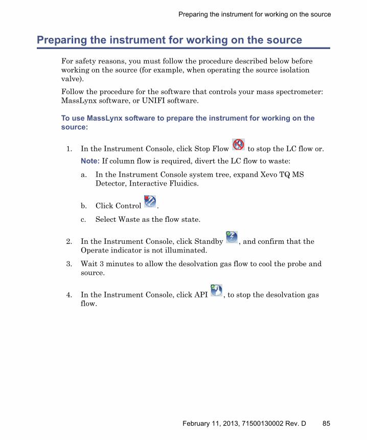
Preparing the instrument for working on the source
Preparing the instrument for working on the source
For safety reasons, you must follow the procedure described below before working on the source (for example, when operating the source isolation valve).
Follow the procedure for the software that controls your mass spectrometer: MassLynx software, or UNIFI software.
To use MassLynx software to prepare the instrument for working on the source:
1. In the Instrument Console, click Stop Flow to stop the LC flow or.
Note: If column flow is required, divert the LC flow to waste:
a. In the Instrument Console system tree, expand Xevo TQ MS Detector, Interactive Fluidics.
b. Click Control .
c. Select Waste as the flow state.
2. In the Instrument Console, click Standby , and confirm that the Operate indicator is not illuminated.
3. Wait 3 minutes to allow the desolvation gas flow to cool the probe and source.
4. In the Instrument Console, click API , to stop the desolvation gas flow.
February 11, 2013, 71500130002 Rev. D 85

4 Maintenance Procedures
To use UNIFI software to prepare the instrument for working on the source:
1. On the System Console tool bar, click Stop Flow to stop the LC flow.
Note: If column flow is required, divert the LC flow to waste:
a. On the Setup pane, click Fluidics.
b. On the Sample Fluidics page, from the Flow Path menu, select Waste.
2. Click Instrument Standby Mode , and confirm that the Operate indicator is not illuminated.
3. Wait 3 minutes to allow the desolvation gas flow to cool the probe and source.
4. Stop the API gas by clicking .
(If the API gas is already stopped, is shown on the tool bar.)
86 February 11, 2013, 71500130002 Rev. D
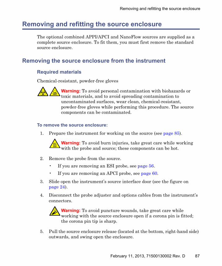
Removing and refitting the source enclosure
Removing and refitting the source enclosure
The optional combined APPI/APCI and NanoFlow sources are supplied as a complete source enclosure. To fit them, you must first remove the standard source enclosure.
Removing the source enclosure from the instrument
Required materials
Chemical-resistant, powder-free gloves
To remove the source enclosure:
1. Prepare the instrument for working on the source (see page 85).
2. Remove the probe from the source.
• If you are removing an ESI probe, see page 56.
• If you are removing an APCI probe, see page 60.
3. Slide open the instrument’s source interface door (see the figure on page 24).
4. Disconnect the probe adjuster and options cables from the instrument’s connectors.
5. Pull the source enclosure release (located at the bottom, right-hand side) outwards, and swing open the enclosure.
Warning: To avoid personal contamination with biohazards or toxic materials, and to avoid spreading contamination to uncontaminated surfaces, wear clean, chemical-resistant, powder-free gloves while performing this procedure. The source components can be contaminated.
Warning: To avoid burn injuries, take great care while working with the probe and source; these components can be hot.
Warning: To avoid puncture wounds, take great care while working with the source enclosure open if a corona pin is fitted; the corona pin tip is sharp.
February 11, 2013, 71500130002 Rev. D 87
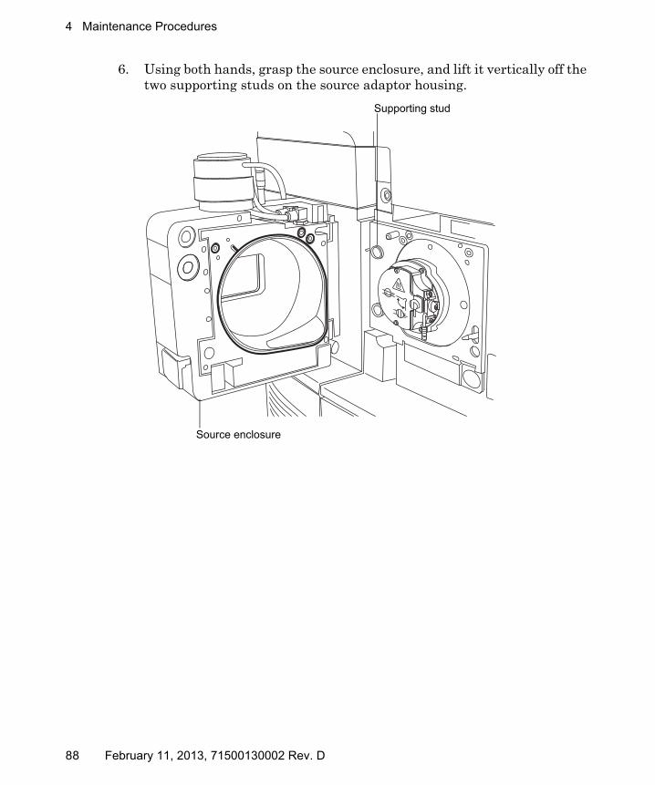
4 Maintenance Procedures
6. Using both hands, grasp the source enclosure, and lift it vertically off the two supporting studs on the source adaptor housing.
TP03164
Supporting stud
Source enclosure
88 February 11, 2013, 71500130002 Rev. D

Removing and refitting the source enclosure
Fitting the source enclosure to the instrument
Required materials
Chemical-resistant, powder-free gloves
To fit the source enclosure:
1. Using both hands, fit the source enclosure to the two supporting studs on the source adaptor housing.
2. Close the source enclosure.
3. Connect the probe adjuster and options cables to the instrument’s connectors.
4. Slide closed the instrument’s source interface door.
Warning: To avoid personal contamination with biohazards or toxic materials, and to avoid spreading contamination to uncontaminated surfaces, wear clean, chemical-resistant, powder-free gloves while performing this procedure. The source components can be contaminated.
Warning: To avoid puncture wounds, take great care while fitting the source enclosure to the source if a corona pin is fitted (the pin tip is sharp).
Caution: To prevent the NanoFlow source sprayer colliding with the cone and breaking, always retract the stage before closing the source enclosure door.
February 11, 2013, 71500130002 Rev. D 89
4 Maintenance Procedures
Installing and removing the corona pin
For ESCi, APCI and dual-mode APCI/APPI operation, you must fit a corona pin.
Installing the corona pin in the source
Required materials
Chemical-resistant, powder-free gloves
To install the corona pin in the source:
1. Prepare the instrument for working on the source (see page 85).
2. Pull the source enclosure release (located at the bottom, right-hand side) outwards, and swing open the enclosure.
Warning: To avoid personal contamination with biohazards or toxic materials, and to avoid spreading contamination to uncontaminated surfaces, wear clean, chemical-resistant, powder-free gloves while performing this procedure. The LC system connections, ESI probe, and source can be contaminated.
Warning: To avoid electric shock, ensure that the instrument is prepared for working on the source when commencing this procedure.
Warning: To avoid burn injuries, take great care while working with the source enclosure open; the source can be hot.
Warning: To avoid puncture wounds, take great care while working with the source enclosure open if an ESI probe is fitted; the ESI probe tip is sharp.
90 February 11, 2013, 71500130002 Rev. D

Installing and removing the corona pin
3. Remove the blanking plug from the corona pin mounting contact.
Tip: Store the blanking plug in a safe location.
Corona pin mounting contact:
4. Fit the corona pin to the mounting contact, ensuring that the corona pin is securely mounted and that its tip aligns with the sample cone aperture.
Corona pin:
5. Close the source enclosure.
Warning: To avoid puncture wounds, handle the corona pin with care; the pin tip is sharp.
TP03130
Corona pin mounting contact blanking plug
TP03130
Corona pin
Sample cone aperture
February 11, 2013, 71500130002 Rev. D 91
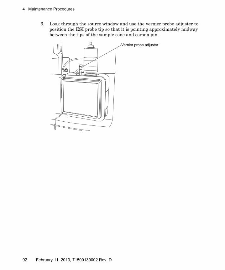
4 Maintenance Procedures
6. Look through the source window and use the vernier probe adjuster to position the ESI probe tip so that it is pointing approximately midway between the tips of the sample cone and corona pin.
TP03128
Vernier probe adjuster
92 February 11, 2013, 71500130002 Rev. D

Installing and removing the corona pin
Removing the corona pin from the source
Required materials
Chemical-resistant, powder-free gloves
To remove the corona pin from the source:
1. Prepare the instrument for working on the source (see page 85).
2. Pull the source enclosure release (located at the bottom, right-hand side) outwards, and swing open the enclosure.
3. Remove the corona pin from its mounting contact (see the figure on page 91).
Tip: Store the corona pin in a safe location.
4. Fit the blanking plug to the corona pin mounting contact (see the figure on page 91).
5. Close the source enclosure.
Warning: To avoid personal contamination with biohazards or toxic materials, and to avoid spreading contamination to uncontaminated surfaces, wear clean, chemical-resistant, powder-free gloves while performing this procedure. The LC system connections, ESI probe, and source can be contaminated.
Warning: To avoid electric shock, ensure that the instrument is prepared for working on the source when commencing this procedure.
Warning: To avoid burn injuries, take great care while working with the instrument’s source enclosure open; the source can be hot.
Warning: To avoid puncture wounds, take great care while working with the source enclosure open if an ESI probe is fitted; the ESI probe tip is sharp.
February 11, 2013, 71500130002 Rev. D 93

4 Maintenance Procedures
Operating the source isolation valve
You must close the source isolation valve to isolate the source from the instrument vacuum system for certain maintenance procedures.
Required materials
Chemical-resistant, powder-free gloves
To close the source isolation valve before starting a maintenance procedure:
1. Prepare the instrument for working on the source (see page 85).
2. Pull the source enclosure release (located at the bottom, right-hand side) outwards and swing open the enclosure.
Warning: To avoid personal contamination with biohazards or toxic materials, and to avoid spreading contamination to uncontaminated surfaces, wear clean, chemical-resistant, powder-free gloves while performing this procedure. The source components can be contaminated.
Warning: To avoid electric shock, ensure that the instrument is suitably prepared before commencing this procedure.
Warning: To avoid burn injuries, take great care while working with the instrument’s source enclosure open; the source can be hot.
Warning: To avoid puncture wounds, take great care while working with the source enclosure open if one or both of these conditions apply:• An ESI probe is fitted (the probe tip is sharp).• A corona pin is fitted (the pin tip is sharp).
94 February 11, 2013, 71500130002 Rev. D

Operating the source isolation valve
3. Close the source isolation valve by moving its handle counterclockwise, to the vertical position.
Isolation valve handle in closed position
February 11, 2013, 71500130002 Rev. D 95

4 Maintenance Procedures
To open the source isolation valve after completing a maintenance procedure:
1. Open the source isolation valve by moving its handle clockwise to the horizontal position.
2. Close the source enclosure.
Warning: To avoid personal contamination with biohazards or toxic materials, and to avoid spreading contamination to uncontaminated surfaces, wear clean, chemical-resistant, powder-free gloves while performing this procedure. The source components can be contaminated.
Warning: To avoid puncture wounds, take great care while working with the source enclosure open if one or both of these conditions apply:• An ESI probe is fitted (the probe tip is sharp).• A corona pin is fitted (the pin tip is sharp).
TP03130
Isolation valve handle in open position
96 February 11, 2013, 71500130002 Rev. D
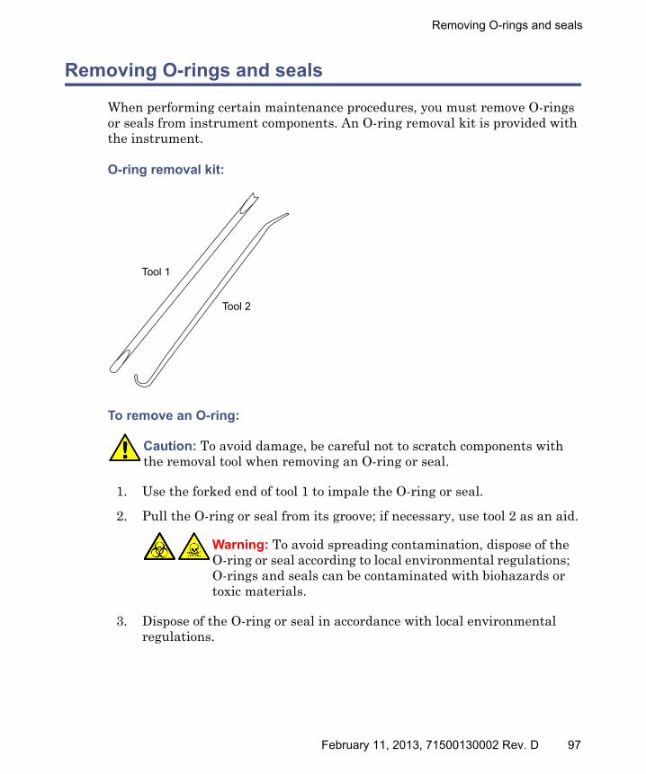
Removing O-rings and seals
Removing O-rings and seals
When performing certain maintenance procedures, you must remove O-rings or seals from instrument components. An O-ring removal kit is provided with the instrument.
O-ring removal kit:
To remove an O-ring:
1. Use the forked end of tool 1 to impale the O-ring or seal.
2. Pull the O-ring or seal from its groove; if necessary, use tool 2 as an aid.
3. Dispose of the O-ring or seal in accordance with local environmental regulations.
Caution: To avoid damage, be careful not to scratch components with the removal tool when removing an O-ring or seal.
Warning: To avoid spreading contamination, dispose of the O-ring or seal according to local environmental regulations; O-rings and seals can be contaminated with biohazards or toxic materials.
Tool 1
Tool 2
February 11, 2013, 71500130002 Rev. D 97

4 Maintenance Procedures
Cleaning the instrument case
Use a soft cloth, dampened with water, to clean the outside surfaces of the mass spectrometer.
Emptying the nitrogen exhaust trap bottle
Inspect the nitrogen exhaust trap bottle in the instrument’s exhaust line, daily and empty it before it is more than approximately 10% full.
Nitrogen exhaust trap bottle:
Caution: To avoid damage, do not use abrasives or solvents to clean the instrument’s case.
TP03164
From instrument exhaust connection
To laboratory exhaust port
Cap
Nitrogen exhaust trap bottle
From instrument pilot valve port
98 February 11, 2013, 71500130002 Rev. D

Emptying the nitrogen exhaust trap bottle
Required materials
Chemical-resistant, powder-free gloves
To empty the nitrogen exhaust trap bottle:
1. To stop the LC flow, follow the action below for your software:
2. Pull the source enclosure release (located at the bottom, right-hand side) outwards, and swing open the enclosure.
3. Unscrew and remove the nitrogen exhaust trap bottle from the cap and associated fittings.
4. Dispose of the waste liquid in accordance with local environmental regulations.
5. Fit and tighten the nitrogen exhaust trap bottle to the cap.
6. Secure the nitrogen exhaust trap bottle in the upright position.
7. Close the source enclosure.
Tip: An automatic leak test will now be performed.
Software Action
MassLynx In the instrument console, click Stop Flow .
UNIFI On the System Console tool bar, click Stop Flow .
Warning: To avoid personal contamination with biohazards or toxic materials, and to avoid spreading contamination to uncontaminated surfaces, wear clean, chemical-resistant, powder-free gloves while handling the nitrogen exhaust trap bottle. The waste liquid in the nitrogen exhaust trap bottle comprises ACQUITY UPLC solvents and analytes.
Warning: To avoid spreading contamination, dispose of waste liquid according to local environmental regulations. The waste liquid can be contaminated with biohazards or toxic materials.
February 11, 2013, 71500130002 Rev. D 99
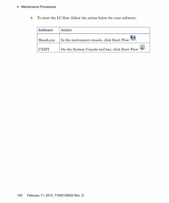
4 Maintenance Procedures
8. To start the LC flow, follow the action below for your software:
Software Action
MassLynx In the instrument console, click Start Flow .
UNIFI On the System Console tool bar, click Start Flow .
100 February 11, 2013, 71500130002 Rev. D

Inspecting the Varian roughing pump oil level
Inspecting the Varian roughing pump oil level
Note: This procedure is not required for an Edwards oil-free roughing pump.
Requirement: You must inspect the oil level while the roughing pump is running.
The roughing pump oil level appears in the roughing pump’s oil level sight glass. Inspect the oil level at weekly intervals; with the pump running, the oil level is typically at approximately 30% to 60% of the maximum oil level. This corresponds to approximately the maximum oil level when the pump is not operating. If the oil level is below these values, add oil to the pump (see “Adding oil to the Varian roughing pump” on page 102).
Roughing pump oil level sight glass:
Caution: To ensure correct operation of the Varian™ roughing pump, do not operate the pump with the oil level at less than 30% of the MAX level.
Maximum oil level
Minimum oil level
February 11, 2013, 71500130002 Rev. D 101

4 Maintenance Procedures
Adding oil to the Varian roughing pump
If the roughing pump oil level is found to be low, you must add oil to the roughing pump. See “Inspecting the Varian roughing pump oil level” on page 101.
Varian roughing pump:
Required materials
• Chemical-resistant, powder-free gloves
• Funnel
• Varian GP45 oil
TP03159
Oil filler plug
Oil level sight glass
Oil drain plug
102 February 11, 2013, 71500130002 Rev. D
Adding oil to the Varian roughing pump
To add oil to the roughing pump:
1. Vent and shut down the mass spectrometer (see the mass spectrometer’s online Help for details).
2. Allow the oil to settle in the pump.
3. Unscrew and remove the roughing pump’s oil filler plug.
Important: To maintain pump performance, use only Varian GP45 oil.
4. Using the funnel, slowly add Varian GP45 oil into the oil filler aperture until the oil reaches the oil level sight glass maximum level.
5. Fit and tighten the roughing pump’s oil filler plug.
6. Start the mass spectrometer (see “Starting the mass spectrometer” on page 42).
Tips: After you add oil to the pump, the following situations can occur:
• The oil level drops slightly during the first month of operation.
• The oil changes color (darkens) over time.
• When the pump approaches operating temperature, any oil spilled becomes odorous.
Warning: To avoid personal contamination with biohazards or toxic materials, always wear chemical-resistant, powder-free gloves when adding or replacing pump oil. The oil can be contaminated with analyte accumulated during normal operation.
Warning: To avoid burn injuries, take great care while working with the roughing pump: it can be hot.
Caution: To avoid oil leakage, when fitting the oil filler plug to the roughing pump,• ensure that the plug is not cross threaded.• do not over-tighten the plug.
February 11, 2013, 71500130002 Rev. D 103

4 Maintenance Procedures
Replacing the Varian roughing pump oil and oil mist filter
Change the roughing pump oil and oil mist filter annually.
This procedure is not required for an Edwards oil-free roughing pump.
Emptying the roughing pump oil
Required materials
• Chemical-resistant, powder-free gloves
• 8-mm Allen wrench
• Container to catch used oil
• Lint-free cloth
To empty the roughing pump oil:
1. Vent and shut down the mass spectrometer (see the mass spectrometer’s online Help for details).
2. Allow the roughing pump to cool.
3. Place the container for capturing the used oil under the pump’s drain plug (see the figure on page 102).
4. Unscrew and remove the oil filler plug.
5. Use the 8-mm Allen wrench to remove the oil drain plug.
Warning: To avoid personal contamination with biohazards or toxic materials, always wear chemical-resistant, powder-free gloves when adding or replacing pump oil. The oil can be contaminated with analyte accumulated during normal operation.
Warning: To avoid burn injuries, take great care while working with the roughing pump: it can be hot.
104 February 11, 2013, 71500130002 Rev. D

Replacing the Varian roughing pump oil and oil mist filter
6. Tip the pump toward the drain plug aperture and allow the oil to drain completely into the container.
7. Dispose of the roughing pump oil in accordance with local environmental regulations.
8. Use the lint-free cloth to remove loose particles from the magnetic tip of the oil drain plug.
Warning: To avoid spreading contamination, dispose of roughing pump oil according to local environmental regulations. The oil can be contaminated with biohazards or toxic materials.
February 11, 2013, 71500130002 Rev. D 105

4 Maintenance Procedures
Replacing the oil mist filter
Required materials
• Chemical-resistant, powder-free gloves
• 3-mm Allen wrench
• New oil mist filter
To replace the oil mist filter:
1. Use the 3-mm Allen wrench to remove the 4 screws securing the oil mist canister cover to the oil mist canister.
2. Remove the oil mist canister cover from the oil mist canister.
Tip: The cover can be tight and difficult to remove.
Warning: To avoid personal contamination with biohazards or toxic materials, always wear chemical-resistant, powder-free gloves when performing this procedure. The oil mist filter and canister components can be contaminated with analyte accumulated during normal operation.
Cover securing screw
Oil mist canister
106 February 11, 2013, 71500130002 Rev. D

Replacing the Varian roughing pump oil and oil mist filter
3. Remove the spring and oil mist filter from the canister.
4. Dispose of the oil mist filter in accordance with local environmental regulations.
5. Install the new oil mist filter in the canister.
Requirement: To seat the new filter properly, press it down firmly when installing it in the canister.
6. Ensure that the O-ring on the oil mist canister cover is correctly seated.
7. Center the spring on top of the oil mist filter.
8. Fit the spring over the collar on the oil mist canister cover, and then fit the cover to the oil mist canister.
9. Use the 3-mm Allen wrench to fit and tighten the 4 screws securing the oil mist canister cover to the oil mist canister.
Warning: To avoid spreading contamination, ensure that the oil mist filter is correctly disposed of according to local environmental regulations.The oil mist filter can be contaminated with biohazards or toxic materials.
Oil mist canister cover
Spring
Oil mist filterO-ring
February 11, 2013, 71500130002 Rev. D 107

4 Maintenance Procedures
To refill the pump with oil
Required materials
• Chemical-resistant, powder-free gloves
• 8-mm Allen wrench
• Funnel
• 1-L bottle of Varian GP45 oil
Refilling the pump with oil:
1. Ensure that the O-ring on the pump’s oil drain plug is clean and properly seated.
2. Use the 8-mm Allen wrench to fit and tighten the roughing pump’s oil drain plug.
Tip: When the oil drain plug is tightened, the plug seals with an O-ring. Compression is controlled by the O-ring groove depth in the plug. Increased torque does not improve the plug seal; it only makes the plug difficult to remove later.
Important: To maintain pump performance, use Varian GP45 oil.
3. Using the funnel, pour 1 L of Varian GP45 oil into the oil filler aperture.
Tip: The oil level may be above the sight-glass MAX level, but should drop to the MAX level or below during the first few days of operation.
Warning: To avoid personal contamination with biohazards or toxic materials, always wear chemical-resistant, powder-free gloves when adding or replacing oil. The roughing pump components can be contaminated with analyte accumulated during normal operation.
Caution: To avoid oil leakage when fitting the oil drain plug to the roughing pump,• ensure that the plug is not cross threaded.• ensure that the O-ring is not pinched.• do not overtighten the plug.
108 February 11, 2013, 71500130002 Rev. D

Replacing the Varian roughing pump oil and oil mist filter
4. Ensure that the O-ring on the oil filler plug is clean and properly seated.
5. Fit and tighten the oil filler plug.
6. Start the mass spectrometer (see “Starting the mass spectrometer” on page 42).
Tip: After you add oil to the pump, the following situations can occur:
• The oil level drops slightly during the first month of operation.
• The oil changes color (darkens) over time.
• After running the pump for 12 to 48 hours, a few drops of oil sometimes appear near the filler plug. Excess oil around the lip of the filler plug flows downwards and drips from the pump when it reaches operating temperature.
• When the pump approaches operating temperature, any oil spilled becomes odorous.
Caution: To avoid oil leakage when fitting the oil filler plug to the roughing pump,• ensure that the plug is not cross threaded.• ensure that the O-ring is not pinched.• do not over tighten the plug.
February 11, 2013, 71500130002 Rev. D 109

4 Maintenance Procedures
Cleaning the source components
Clean the sample cone and cone gas nozzle when these conditions apply:
• The sample cone and cone gas nozzle are visibly fouled.
• LC and sample-related causes for decreased signal intensity have been dismissed.
See “Cleaning the sampling cone assembly” on page 111.
If cleaning the sample cone and cone gas nozzles fails to increase signal sensitivity, also clean the extraction cone. See “Cleaning the extraction cone” on page 120.
If cleaning the extraction cone fails to increase signal sensitivity, clean the ion block and isolation valve. See “Cleaning the ion block assembly” on page 128.
If cleaning the ion block and isolation valve fails to increase signal sensitivity, also clean the source hexapole assembly. See “Cleaning the source hexapole assembly” on page 140.
110 February 11, 2013, 71500130002 Rev. D
Cleaning the sampling cone assembly
Cleaning the sampling cone assembly
You can remove the sampling cone assembly (comprising the sample cone, O-ring, and cone gas nozzle) for cleaning without venting the instrument.
Removing the sampling cone assembly from the source
Required materials
Chemical-resistant, powder-free gloves
Warning: To avoid personal contamination with biohazards or toxic materials, and to avoid spreading contamination to uncontaminated surfaces, wear clean, chemical-resistant, powder-free gloves when performing this procedure. The source components can be contaminated.
Warning: To avoid electric shock, ensure that the instrument is in Standby mode before commencing this procedure.
Warning: To avoid puncture wounds, take great care while working with the source enclosure open if one or both of these conditions apply:• An ESI probe is fitted (the probe tip is sharp).• A corona pin is fitted (the pin tip is sharp).
Warning: To avoid burn injuries, take great care while working with the source enclosure open; the source can be hot.
February 11, 2013, 71500130002 Rev. D 111

4 Maintenance Procedures
To remove the sampling cone assembly from the source:
1. Close the source isolation valve (see “To close the source isolation valve before starting a maintenance procedure:” on page 94).
2. Grasp the cone gas nozzle handle, and use it to rotate the sampling cone assembly 90 degrees, moving the handle from the vertical to the horizontal position.
3. Slide the sampling cone assembly out of the ion block assembly.
Caution: To avoid damaging the instrument by sudden venting, do not open the isolation valve at any time while the sampling cone assembly is removed from the ion block assembly.
TP03131
Cone gas nozzle handle
Sampling cone assembly
TP03132
Ion block assembly
112 February 11, 2013, 71500130002 Rev. D

Cleaning the sampling cone assembly
Disassembling the sampling cone assembly
Required materials
• Chemical-resistant, powder-free gloves
• Combined 2.5-mm Allen wrench and cone extraction tool
To disassemble the sampling cone assembly:
1. On the combined 2.5-mm Allen wrench and cone extraction tool, slide the collar to the end of the tool.
2. Insert the collar in the sample cone.
Warning: To avoid personal contamination with biohazards or toxic materials, and to avoid spreading contamination to uncontaminated surfaces, wear clean, chemical-resistant, powder-free gloves when working with the sampling cone assembly.
Collar
February 11, 2013, 71500130002 Rev. D 113
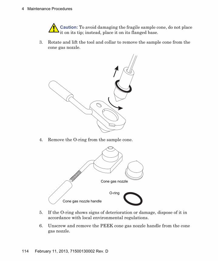
4 Maintenance Procedures
3. Rotate and lift the tool and collar to remove the sample cone from the cone gas nozzle.
4. Remove the O-ring from the sample cone.
5. If the O-ring shows signs of deterioration or damage, dispose of it in accordance with local environmental regulations.
6. Unscrew and remove the PEEK cone gas nozzle handle from the cone gas nozzle.
Caution: To avoid damaging the fragile sample cone, do not place it on its tip; instead, place it on its flanged base.
Cone gas nozzle
O-ring
Cone gas nozzle handle
114 February 11, 2013, 71500130002 Rev. D

Cleaning the sampling cone assembly
Cleaning the sample cone and cone gas nozzle
Required materials
• Chemical-resistant, powder-free gloves.
• Appropriately sized glass vessels in which to completely immerse components when cleaning. Use only glassware not previously cleaned with surfactants.
• HPLC-grade (or better) methanol.
• HPLC-grade (or better) water.
• Formic acid.
• Ultrasonic bath.
• Source of oil-free, inert gas (nitrogen or argon) for drying (air-drying optional).
• Wash bottle containing HPLC-grade (or better) 1:1 methanol/water.
• Large beaker.
To clean the sample cone and cone gas nozzle:
1. If the sample cone contains debris, place a drop of formic acid on its aperture.
2. Immerse the sample cone, cone gas nozzle, and cone gas nozzle handle in separate glass vessels containing 1:1 methanol/water.
Tip: If the components are obviously contaminated, use 45:45:10 methanol/water/formic acid.
Warning: To avoid personal contamination with biohazards or toxic materials, and to avoid spreading contamination to uncontaminated surfaces, wear clean, chemical-resistant, powder-free gloves when working with the sample cone and cone gas nozzle.
Warning: To avoid injury, work with extreme care. Use a fume hood, and suitable protective equipment. Formic acid is extremely corrosive and toxic.
Caution: To avoid damaging the fragile sample cone, do not place it on its tip; instead, place it on its flanged base.
February 11, 2013, 71500130002 Rev. D 115

4 Maintenance Procedures
3. Place the vessels in the ultrasonic bath for 30 minutes.
4. If you used formic acid in the cleaning solution, do as follows:
a. Rinse the components by immersing them in separate glass vessels containing water and then placing the vessels in the ultrasonic bath for 20 minutes.
b. Remove any residual water from the extraction cone by immersing it in a glass vessel containing methanol and then placing the vessel in the ultrasonic bath for 10 minutes.
5. Carefully remove the components from the vessels, and blow-dry them with inert, oil-free gas.
6. Inspect each component for persisting contamination. If contamination is present, do as follows:
a. Use the wash bottle containing 1:1 methanol/water to rinse the component over the large beaker.
b. Blow-dry the component with inert, oil-free gas.
7. Inspect each component for persisting contamination. If contamination is present, dispose of the component, and obtain a new one before reassembling the sampling cone assembly.
Caution: To avoid recontaminating the components, wear clean, chemical-resistant, powder-free gloves for the rest of this procedure.
116 February 11, 2013, 71500130002 Rev. D

Cleaning the sampling cone assembly
Assembling the sampling cone assembly
Required materials
Chemical-resistant, powder-free gloves
To assemble the sampling cone assembly:
1. Fit the cone gas nozzle handle to the cone gas nozzle and turn the handle clockwise to tighten.
2. Carefully fit the sample cone into the cone gas nozzle.
3. Fit the O-ring into the groove created between the sample cone and cone gas nozzle. (Fit a new O-ring if the old one has been disposed of.)
Caution:
• To avoid recontaminating the sampling cone assembly, wear clean chemical-resistant, powder-free gloves during this procedure.
• To avoid damaging the fragile sample cone, do not place it on its tip; instead, place it on its flanged base.
TP02663
O-ring
Sample cone
Cone gas nozzle
Cone gas nozzle handle
February 11, 2013, 71500130002 Rev. D 117
4 Maintenance Procedures
Fitting the sampling cone assembly to the source
Required material
Chemical-resistant, powder-free gloves
Warning: To avoid personal contamination with biohazards or toxic materials, and to avoid spreading contamination to uncontaminated surfaces, wear clean, chemical-resistant, powder-free gloves when working with the source components.
Warning: To avoid puncture wounds, take great care while working with the source enclosure open if one or both of these conditions apply:• An ESI probe is fitted (the probe tip is sharp).• A corona pin is fitted (the pin tip is sharp).
Caution: To avoid damaging the instrument by sudden venting, do not open the source isolation valve before fitting the sampling cone assembly to the ion block assembly.
118 February 11, 2013, 71500130002 Rev. D

Cleaning the sampling cone assembly
To fit the sampling cone assembly to the source:
1. Ensure that the source isolation valve is in the closed position (see “To close the source isolation valve before starting a maintenance procedure:” on page 94).
2. Hold the sampling cone assembly so that the cone gas nozzle handle is oriented horizontally and at the top, and then slide the sampling cone assembly into the ion block assembly.
3. Grasp the cone gas nozzle handle and use it to rotate the sampling cone assembly 90 degrees, moving the handle downward from the horizontal to the vertical position.
4. Open the source isolation valve (see “To open the source isolation valve after completing a maintenance procedure:” on page 96).
5. Close the source enclosure.
TP03132
Ion block assembly
Sampling cone assembly
February 11, 2013, 71500130002 Rev. D 119

4 Maintenance Procedures
Cleaning the extraction cone
Clean the ion block and extraction cone when cleaning the sample cone and cone gas nozzle fails to increase signal sensitivity. You must remove the ion block assembly from the source assembly to clean the extraction cone.
Removing the ion block assembly from the source assembly
Required materials
• Chemical-resistant, powder-free gloves
• Combined 2.5-mm Allen wrench and cone extraction tool
To remove the ion block assembly:
1. Vent and shut down the mass spectrometer (see the mass spectrometer’s online Help for details).
2. Close the source isolation valve (see “To close the source isolation valve before starting a maintenance procedure:” on page 94).
Warning: To avoid personal contamination with biohazards or toxic materials, and to avoid spreading contamination to uncontaminated surfaces, wear clean, chemical-resistant, powder-free gloves when working with the source components.
Warning: To avoid burn injuries, allow the source to cool for at least 30 minutes before proceeding; the source can be hot.
Warning: To avoid puncture wounds, take great care while working with the source enclosure open if one or both of these conditions apply:• An ESI probe is fitted (the probe tip is sharp).• A corona pin is fitted (the pin tip is sharp).
120 February 11, 2013, 71500130002 Rev. D
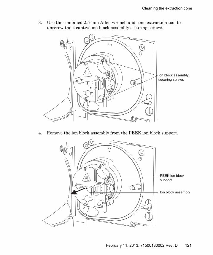
Cleaning the extraction cone
3. Use the combined 2.5-mm Allen wrench and cone extraction tool to unscrew the 4 captive ion block assembly securing screws.
4. Remove the ion block assembly from the PEEK ion block support.
TP03130
Ion block assembly securing screws
TP03130
Ion block assembly
PEEK ion block support
February 11, 2013, 71500130002 Rev. D 121
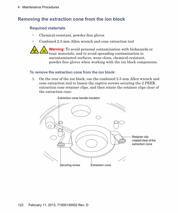
4 Maintenance Procedures
Removing the extraction cone from the ion block
Required materials
• Chemical-resistant, powder-free gloves
• Combined 2.5-mm Allen wrench and cone extraction tool
To remove the extraction cone from the ion block:
1. On the rear of the ion block, use the combined 2.5-mm Allen wrench and cone extraction tool to loosen the captive screws securing the 2 PEEK extraction cone retainer clips, and then rotate the retainer clips clear of the extraction cone.
Warning: To avoid personal contamination with biohazards or toxic materials, and to avoid spreading contamination to uncontaminated surfaces, wear clean, chemical-resistant, powder-free gloves when working with the ion block components.
Securing screw Extraction cone
Retainer clip rotated clear of the extraction cone
Extraction cone handle insulator
122 February 11, 2013, 71500130002 Rev. D
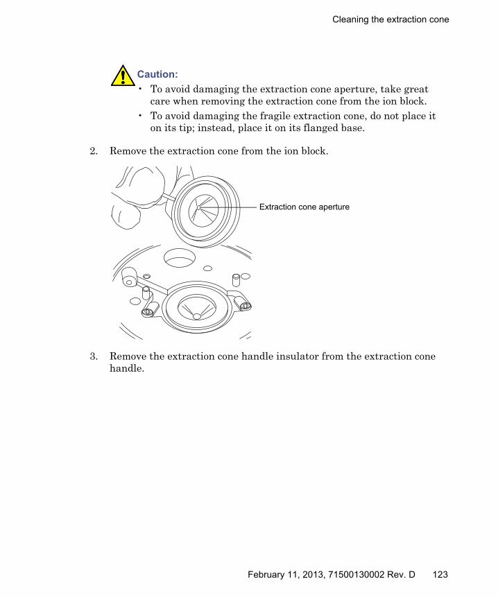
Cleaning the extraction cone
2. Remove the extraction cone from the ion block.
3. Remove the extraction cone handle insulator from the extraction cone handle.
Caution:
• To avoid damaging the extraction cone aperture, take great care when removing the extraction cone from the ion block.
• To avoid damaging the fragile extraction cone, do not place it on its tip; instead, place it on its flanged base.
Extraction cone aperture
February 11, 2013, 71500130002 Rev. D 123

4 Maintenance Procedures
Cleaning the extraction cone
Required materials
• Chemical-resistant, powder-free gloves.
• Appropriately sized glass vessel in which to completely immerse the extraction cone when cleaning. Use only glassware not previously cleaned with surfactants.
• HPLC-grade (or better) methanol.
• HPLC-grade (or better) water.
• Formic acid.
• Ultrasonic bath.
• Source of oil-free, inert gas (for example, nitrogen) for drying (air-drying optional).
• Wash bottle containing HPLC-grade (or better) 1:1 methanol/water.
• Large beaker.
To clean the extraction cone:
1. Immerse the extraction cone in the glass vessel containing 1:1 methanol/water.
Tip: If the extraction cone is obviously contaminated, use 45:45:10 methanol/water/formic acid.
2. Place the vessel in the ultrasonic bath for 30 minutes.
Warning: To avoid personal contamination with biohazards or toxic materials, and to avoid spreading contamination to uncontaminated surfaces, wear clean, chemical-resistant, powder-free gloves when working with the extraction cone.
Warning: To avoid injury, work with extreme care. Use a fume hood, and suitable protective equipment. Formic acid is extremely corrosive and toxic.
Caution: To avoid damaging the fragile extraction cone, do not place it on its tip; instead, place it on its flanged base.
124 February 11, 2013, 71500130002 Rev. D

Cleaning the extraction cone
3. If you used formic acid in the cleaning solution, do as follows:
a. Rinse the extraction cone by immersing it in a glass vessel containing water and then placing the vessel in the ultrasonic bath for 20 minutes.
b. Dry the components by immersing them in separate glass vessels containing methanol and then placing the vessels in the ultrasonic bath for 10 minutes.
4. Carefully remove the extraction cone from the vessel, and blow-dry it using inert, oil-free gas.
5. Inspect the extraction cone for persisting contamination. If contamination is present, do as follows:
a. Use the wash bottle containing 1:1 methanol/water to rinse the extraction cone over the large beaker.
b. Blow-dry the extraction cone with inert, oil-free gas.
6. Inspect the extraction cone for persisting contamination. If contamination is present, dispose of the extraction cone, and obtain a new one.
Caution: To avoid recontaminating the extraction cone, wear clean, chemical-resistant, powder-free gloves for the rest of this procedure.
Warning: To avoid spreading contamination, dispose of the extraction cone in accordance with local environmental regulations.
February 11, 2013, 71500130002 Rev. D 125

4 Maintenance Procedures
Fitting the extraction cone to the ion block
Required materials
• Chemical-resistant, powder-free gloves
• Combined 2.5-mm Allen wrench and cone extraction tool
To fit the extraction cone to the ion block:
1. Fit the extraction cone handle insulator to the extraction cone handle.
2. Fit the extraction cone to the ion block.
3. Rotate the 2 PEEK extraction cone retainer clips to secure the extraction cone, then use the combined 2.5-mm Allen wrench and cone extraction tool to tighten the retainer clip securing screws.
Fitting the ion block assembly to the source assembly
Required materials
• Chemical-resistant, powder-free gloves
• Combined 2.5-mm Allen wrench and cone extraction tool
Warning: To avoid personal contamination with biohazards or toxic materials, and to avoid spreading contamination to uncontaminated surfaces, wear clean, chemical-resistant, powder-free gloves when working with the ion block.
Warning: To avoid personal contamination with biohazards or toxic materials, and to avoid spreading contamination to uncontaminated surfaces, wear clean, chemical-resistant, powder-free gloves when working with the source components.
Warning: To avoid puncture wounds, take great care while working with the source enclosure open if one or both of these conditions apply:• An ESI probe is fitted (the probe tip is sharp).• A corona pin is fitted (the pin tip is sharp).
126 February 11, 2013, 71500130002 Rev. D

Cleaning the extraction cone
To fit the ion block assembly to the source assembly:
1. Fit the ion block assembly to the PEEK ion block support.
2. Use the combined 2.5-mm Allen wrench and cone extraction tool to fit and then slowly tighten the 4 ion block assembly securing screws sequentially and in small increments.
3. Open the source isolation valve (see “Operating the source isolation valve” on page 94).
4. Close the source enclosure.
Caution: To avoid recontaminating the ion block assembly, wear clean chemical-resistant, powder-free gloves during this procedure.
February 11, 2013, 71500130002 Rev. D 127

4 Maintenance Procedures
Cleaning the ion block assembly
Clean the ion block assembly if cleaning the sample cone, cone gas nozzle, and extraction cone fails to increase signal sensitivity.
Disassembling the source ion block assembly
Required materials
• Chemical-resistant, powder-free gloves
• Combined 2.5-mm Allen wrench and cone extraction tool
• O-ring removal kit
• Needle-nose pliers
128 February 11, 2013, 71500130002 Rev. D

Cleaning the ion block assembly
To disassemble the ion block assembly:
1. Remove the ion block assembly from the source assembly (see “Removing the ion block assembly from the source assembly” on page 120).
2. Ensure that the isolation valve is closed.
3. Grasp the cone gas nozzle handle and use it to rotate the sampling cone assembly through 90 degrees.
4. Slide the sampling cone assembly out of the ion block assembly.
Warning: To avoid personal contamination with biohazards or toxic materials, and to avoid spreading contamination to uncontaminated surfaces, wear clean, chemical-resistant, powder-free gloves when working with the ion block assembly.
Caution: To ensure correct operation of the ion block assembly after reassembly,• do not remove the sampling cone assembly retaining blocks.• do not adjust the screws securing the sampling cone assembly
retaining blocks.
Isolation valve handle in closed position
Sampling cone assembly retaining blocks
Cone gas nozzle handle
February 11, 2013, 71500130002 Rev. D 129

4 Maintenance Procedures
5. Use the combined 2.5-mm Allen wrench and cone extraction tool to loosen the 2 ion block cover plate captive securing screws.
6. Remove the ion block cover plate.
7. Grasp the isolation valve and pull it out of the ion block.
Ion block cover plate securing screw
Ion block cover plate
Isolation valve
O-ring
130 February 11, 2013, 71500130002 Rev. D

Cleaning the ion block assembly
8. Use the O-ring removal kit to carefully remove the isolation valve O-ring (see “Removing O-rings and seals” on page 97).
9. If the isolation valve O-ring shows signs of deterioration or damage, dispose of it in accordance with local environmental regulations.
10. Use the combined 2.5-mm Allen wrench and cone extraction tool to loosen the captive PEEK terminal block securing screw.
11. Use the needle-nose pliers to grasp the PEEK terminal block and partially lift it out of the ion block.
Warning: To prevent spreading contamination, dispose of the isolation valve O-ring according to local environmental regulations. The O-ring can be contaminated with biohazards or toxic materials.
Caution: To avoid damaging the heater cartridge assembly wires, do not bend or twist them when removing the assembly from the ion block.
PEEK terminal block securing screw
February 11, 2013, 71500130002 Rev. D 131
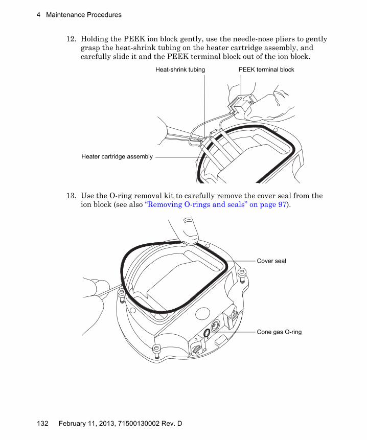
4 Maintenance Procedures
12. Holding the PEEK ion block gently, use the needle-nose pliers to gently grasp the heat-shrink tubing on the heater cartridge assembly, and carefully slide it and the PEEK terminal block out of the ion block.
13. Use the O-ring removal kit to carefully remove the cover seal from the ion block (see also “Removing O-rings and seals” on page 97).
Heat-shrink tubing
Heater cartridge assembly
PEEK terminal block
Cover seal
Cone gas O-ring
132 February 11, 2013, 71500130002 Rev. D

Cleaning the ion block assembly
14. Use the O-ring removal kit to carefully remove the cone gas O-ring from the ion block.
15. If the cover seal or cone gas O-ring shows signs of deterioration or damage, dispose of it in accordance with local environmental regulations.
16. Insert the combined 2.5-mm Allen wrench and cone extraction tool through the hole in the ion block blanking plug, and then unscrew and remove the ion block blanking plug and associated seal.
17. If the blanking plug seal shows signs of deterioration or damage, dispose of it in accordance with local environmental regulations.
Warning: To avoid spreading contamination, dispose of the cover seal and cone gas O-ring according to local environmental regulations. They can be contaminated with biohazards or toxic materials.
Warning: To avoid spreading contamination, dispose of the blanking plug seal according to local environmental regulations. It can be contaminated with biohazards or toxic materials.
Blanking plug
Combined 2.5-mm Allen wrench and cone extraction tool
February 11, 2013, 71500130002 Rev. D 133

4 Maintenance Procedures
18. Use the combined 2.5-mm Allen wrench and cone extraction tool to remove the captive screws securing the 2 PEEK extraction cone retainer clips.
19. Remove the extraction cone from the ion block.
Caution:
• To avoid damaging the extraction cone aperture, take great care when removing the extraction cone from the ion block.
• To avoid damaging the fragile extraction cone, do not place it on its tip; instead, place it on its flanged base.
Securing screw
Extraction cone
Retainer clip
Extraction cone aperture
134 February 11, 2013, 71500130002 Rev. D

Cleaning the ion block assembly
20. Remove the extraction cone handle insulator from the extraction cone handle.
21. Remove the extraction cone seal from the ion block.
Extraction cone seal
February 11, 2013, 71500130002 Rev. D 135

4 Maintenance Procedures
Cleaning the ion block components
Required materials
• Chemical-resistant, powder-free gloves.
• Appropriately sized glass vessels in which to completely immerse components when cleaning. Use only glassware not previously cleaned with surfactants.
• HPLC-grade (or better) methanol.
• HPLC-grade (or better) water.
• Formic acid.
• Ultrasonic bath.
• Source of oil-free, inert gas (for example, nitrogen) for drying (air-drying optional).
• Wash bottle containing HPLC-grade (or better) 1:1 methanol/water.
• Large beaker.
To clean the ion block components:
1. Immerse the ion block and isolation valve in separate glass vessels containing 1:1 methanol/water.
Tip: If the components are obviously contaminated, use 45:45:10 methanol/water/formic acid.
2. Place the vessels in the ultrasonic bath for 30 minutes.
Warning: To avoid personal contamination with biohazards or toxic materials, and to avoid spreading contamination to uncontaminated surfaces, wear clean, chemical-resistant, powder-free gloves when working with the ion block components.
Warning: To avoid injury, work with extreme care. Use a fume hood, and suitable protective equipment. Formic acid is extremely corrosive and toxic.
136 February 11, 2013, 71500130002 Rev. D
Cleaning the ion block assembly
3. If you used formic acid in the cleaning solution, do as follows:
a. Rinse the components by immersing them separately in glass vessels containing water and then placing the vessels in the ultrasonic bath for 20 minutes.
b. Dry the components by immersing them in separate glass vessels containing methanol and then placing the vessels in the ultrasonic bath for 10 minutes.
4. Carefully remove the components from the vessels, and blow-dry them using inert, oil-free gas.
5. Inspect each component for persisting contamination. If contamination is present, do as follows:
a. Use the wash bottle containing 1:1 methanol/water to rinse the component over the large beaker.
b. Blow-dry the component with inert, oil-free gas.
6. Inspect each component for persisting contamination. If contamination is present, dispose of the component, and obtain a new one before reassembly.
Caution: To avoid recontaminating the components, wear clean, chemical-resistant, powder-free gloves for the rest of this procedure.
Warning: To avoid spreading contamination, dispose of the components in accordance with local environmental regulations.
February 11, 2013, 71500130002 Rev. D 137
4 Maintenance Procedures
Assembling the source ion block assembly
Required materials
• Chemical-resistant, powder-free gloves
• Combined 2.5-mm Allen wrench and cone extraction tool
• Needle-nose pliers
• Isopropyl alcohol in small container
To assemble the ion block assembly:
1. Fit the extraction cone seal to the ion block.
2. Fit the extraction cone handle insulator to the extraction cone handle.
3. Fit the extraction cone to the ion block.
4. Fit the 2 PEEK extraction cone retainer clips to the ion block.
5. Use the combined 2.5-mm Allen wrench and cone extraction tool to tighten the captive screw securing each extraction cone retainer clip to the ion block.
6. Fit the blanking plug seal to the ion block blanking plug. (Fit a new seal if the old one has been disposed of.)
7. Fit the blanking plug to the ion block and finger tighten it.
8. Insert the combined 2.5-mm Allen wrench and cone extraction tool through the hole in the blanking plug and use it to fully tighten the plug.
Caution:
• To avoid recontaminating the ion block assembly, wear clean chemical-resistant, powder-free gloves during this procedure.
• To avoid damaging the fragile extraction cone, do not place it on its tip; instead, place it on its flanged base.
Caution: To avoid damaging the extraction cone aperture, take great care when fitting the extraction cone to the ion block.
138 February 11, 2013, 71500130002 Rev. D

Cleaning the ion block assembly
9. Using the needle-nose pliers to gently grasp the heat-shrink tubing on the heater cartridge assembly, slide the assembly and the PEEK terminal block into the ion block.
10. Use the combined 2.5-mm Allen wrench and cone extraction tool to tighten the captive PEEK terminal block securing screw.
11. Ensure that the grooves for the cover seal, cone gas O-ring, and isolation valve O-ring are free from dirt and debris.
Tip: If contamination is present, use 1:1 methanol/water, applied to a lint-free cloth, to carefully clean the grooves.
12. Fit the cover seal to the ion block, ensuring that it is correctly seated. (Fit a new seal if the old one has been disposed of.)
13. Fit the cone gas O-ring to the ion block, ensuring that it is correctly seated. (Fit a new O-ring if the old one has been disposed of.)
14. If the old isolation valve O-ring has been disposed of, soak a new O-ring in isopropyl alcohol for a few minutes.
Rationale: Doing so lubricates the O-ring and aids your fitting the O-ring to the isolation valve.
15. Fit the O-ring to the isolation valve.
16. Fit the isolation valve to the ion block assembly, so that it is in the closed position.
17. Fit the ion block cover plate to the ion block assembly, and then use the combined 2.5-mm Allen wrench and cone extraction tool to tighten the 2 ion block cover plate captive securing screws.
18. Hold the sampling cone assembly so that the cone gas nozzle handle is oriented horizontally and at the top, and then slide the sampling cone assembly into the ion block assembly.
19. Grasp the sampling cone assembly handle, and use it to rotate the sampling cone assembly through 90 degrees.
20. Fit the ion block assembly to the source assembly (see “Fitting the ion block assembly to the source assembly” on page 126).
Caution: To avoid damaging the heater cartridge assembly wires, do not bend or twist them when fitting the assembly to the ion block.
February 11, 2013, 71500130002 Rev. D 139

4 Maintenance Procedures
Cleaning the source hexapole assembly
Clean the source hexapole assembly if cleaning the ion block, isolation valve, and extraction cone fails to increase signal sensitivity.
Removing the ion block assembly, ion block support, and hexapole from the source assembly
Required materials
• Chemical-resistant, powder-free gloves
• 3-mm Allen wrench
• O-ring removal kit
To remove the ion block assembly, ion block support, and hexapole:
1. Remove the ion block assembly from the PEEK ion block support (see “Removing the ion block assembly from the source assembly” on page 120).
Warning: To avoid personal contamination with biohazards or compounds that are toxic or corrosive, and to avoid spreading contamination to uncontaminated surfaces, wear clean, chemical-resistant, powder-free gloves when working with the source components.
140 February 11, 2013, 71500130002 Rev. D

Cleaning the source hexapole assembly
2. Use the 3-mm Allen wrench to unscrew and remove the 4 screws securing the PEEK ion block support to the adaptor housing.
3. Remove the PEEK ion block support from the adaptor housing.
4. Use the O-ring removal kit to carefully remove all the O-rings from the PEEK ion block support (see “Removing O-rings and seals” on page 97).
5. If any of the O-rings show signs of deterioration or damage, dispose of them in accordance with local environmental regulations.
6. Carefully grasp the source hexapole assembly and remove it from the adaptor housing.
Warning: To avoid contaminating uncontaminated surfaces with biohazards or compounds that are toxic or corrosive, dispose of the O-rings according to local environmental regulations.
Caution: To avoid damage when removing the hexapole assembly from the adaptor housing:• avoid scratching the internal surfaces of the adaptor block.• do not compress the hexapole rods.
Securing screws
PEEK ion block support
Adaptor housing
Hexapole assembly
February 11, 2013, 71500130002 Rev. D 141

4 Maintenance Procedures
Cleaning the hexapole assembly
Required materials
• Chemical-resistant, powder-free gloves.
• 500-mL measuring cylinder or appropriately sized glass vessel in which to completely immerse the hexapole when cleaning. Use only glassware not previously cleaned with surfactants.
• Length of small diameter PEEK or Teflon® tubing appropriately sized for suspending the hexapole in the glass vessel when cleaning.
• HPLC-grade (or better) methanol.
• Ultrasonic bath.
• Source of oil-free, inert gas (for example, nitrogen) for drying (air-drying optional).
• HPLC-grade (or better) 1:1 methanol/water.
• Wash bottle containing HPLC-grade (or better) 1:1 methanol/water.
• Large beaker.
• Small, flat-blade screwdriver.
To clean the source hexapole assembly:
1. Bend the PEEK or Teflon tube into a hook shape.
2. Insert one end of the hook into one of the holes on the hexapole assembly’s rear support ring.
3. Use the hook to carefully suspend the hexapole assembly in the glass vessel so that the bottom of the assembly does not touch the bottom of the vessel.
Warning: To avoid personal contamination with biohazards or compounds that are toxic or corrosive, and to avoid spreading contamination to uncontaminated surfaces, wear clean, chemical-resistant, powder-free gloves when working with the source hexapole assembly.
Caution: To avoid vibration damage to the hexapole assembly, ensure that the bottom of the assembly is not in contact with the bottom of the glass vessel.
142 February 11, 2013, 71500130002 Rev. D
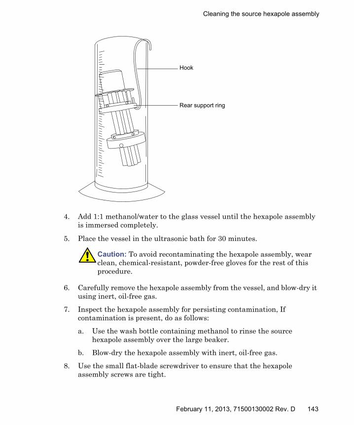
Cleaning the source hexapole assembly
4. Add 1:1 methanol/water to the glass vessel until the hexapole assembly is immersed completely.
5. Place the vessel in the ultrasonic bath for 30 minutes.
6. Carefully remove the hexapole assembly from the vessel, and blow-dry it using inert, oil-free gas.
7. Inspect the hexapole assembly for persisting contamination, If contamination is present, do as follows:
a. Use the wash bottle containing methanol to rinse the source hexapole assembly over the large beaker.
b. Blow-dry the hexapole assembly with inert, oil-free gas.
8. Use the small flat-blade screwdriver to ensure that the hexapole assembly screws are tight.
Caution: To avoid recontaminating the hexapole assembly, wear clean, chemical-resistant, powder-free gloves for the rest of this procedure.
TP02658
Hook
Rear support ring
February 11, 2013, 71500130002 Rev. D 143

4 Maintenance Procedures
Fitting the hexapole assembly, PEEK ion block support, and ion block assembly to the source assembly
Required materials
• Chemical-resistant, powder-free gloves
• 3-mm Allen wrench
• Lint-free cloth
• HPLC-grade (or better) 1:1 methanol/water
• New seals and O-rings
To fit the hexapole assembly and PEEK ion block support to the source:
1. Carefully fit the source hexapole assembly into the adaptor housing, aligning the notches in the differential aperture at its rear with the two bottom support rails on the analyzer assembly. Then carefully slide the assembly fully into place.
2. Ensure that the grooves for the PEEK ion block support O-rings are free from dirt and debris.
Tip: If contamination is present, use 1:1 methanol/water, applied to a lint-free cloth, to carefully clean the grooves.
3. Fit the O-rings to the PEEK ion block support. Fit new O-rings if any of the old O-rings were disposed of.
Tip: To fit an O-ring in its groove, start fitting the O-ring at the notch in the groove, and then progressively work the ring into the groove, in either direction from the notch.
Caution: To avoid recontaminating the source, wear clean, chemical-resistant, powder-free gloves during this procedure.
Caution: To avoid damage when fitting the hexapole assembly into the adaptor housing:• avoid scratching the internal surfaces of the adaptor block.• do not compress the hexapole rods.
144 February 11, 2013, 71500130002 Rev. D
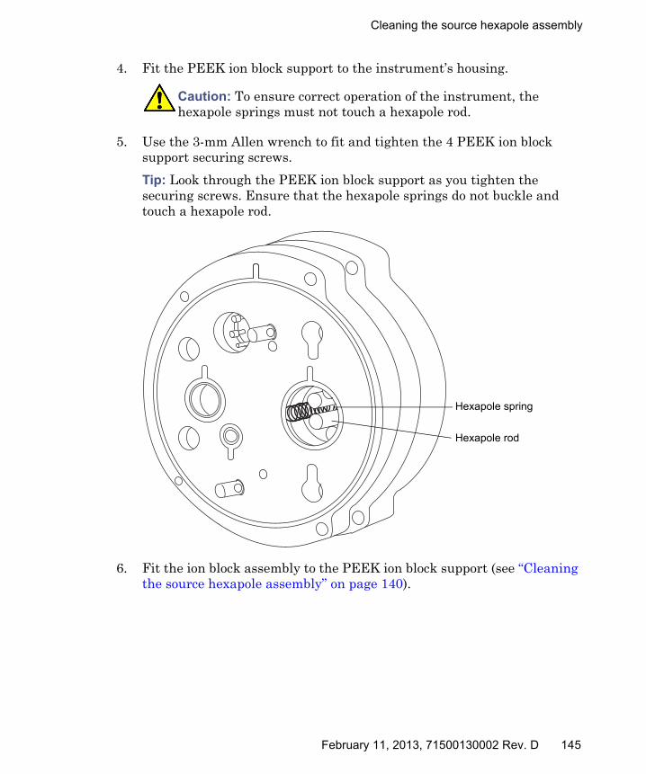
Cleaning the source hexapole assembly
4. Fit the PEEK ion block support to the instrument’s housing.
5. Use the 3-mm Allen wrench to fit and tighten the 4 PEEK ion block support securing screws.
Tip: Look through the PEEK ion block support as you tighten the securing screws. Ensure that the hexapole springs do not buckle and touch a hexapole rod.
6. Fit the ion block assembly to the PEEK ion block support (see “Cleaning the source hexapole assembly” on page 140).
Caution: To ensure correct operation of the instrument, the hexapole springs must not touch a hexapole rod.
Hexapole spring
Hexapole rod
February 11, 2013, 71500130002 Rev. D 145

4 Maintenance Procedures
Replacing the ESI probe tip and gasket
Replace the ESI probe tip if a blockage occurs in the internal metal sheathing through which the stainless steel capillary passes or if the probe tip is damaged.
Removing the ESI probe tip and gasket
Required materials
• Chemical-resistant, powder-free gloves
• 7-mm wrench
• 10-mm wrench
To remove the ESI probe tip and gasket:
1. Remove the ESI probe from the source (see “Removing the ESI probe” on page 56).
Warning: To avoid personal contamination with biohazards or compounds that are toxic or corrosive, and to avoid spreading contamination to uncontaminated surfaces, wear clean, chemical-resistant, powder-free gloves when working with the probe and source components.
Warning: To avoid burn injuries, take great care while performing this procedure; the probe and source can be hot.
Warning: To avoid puncture wounds, handle the probe with care; the ESI probe tip is sharp.
146 February 11, 2013, 71500130002 Rev. D

Replacing the ESI probe tip and gasket
2. Use the 10-mm wrench to remove the probe tip.
Tip: If the probe tip is difficult to remove, use the 7-mm wrench in conjunction with the 10-mm wrench.
Probe tip
10-mm wrench
Probe tip
7-mm wrench
10-mm wrench
February 11, 2013, 71500130002 Rev. D 147
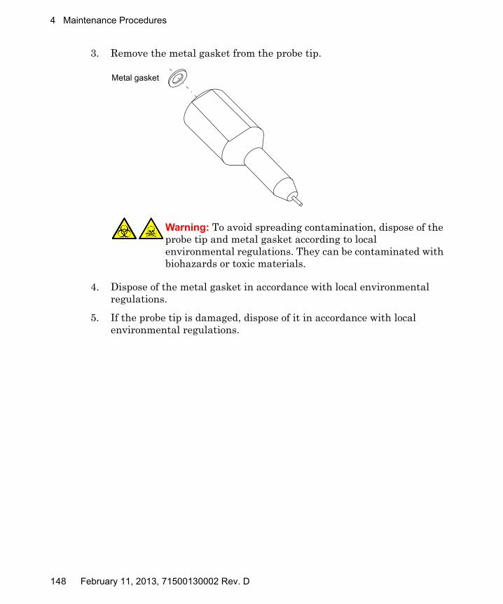
4 Maintenance Procedures
3. Remove the metal gasket from the probe tip.
4. Dispose of the metal gasket in accordance with local environmental regulations.
5. If the probe tip is damaged, dispose of it in accordance with local environmental regulations.
Warning: To avoid spreading contamination, dispose of the probe tip and metal gasket according to local environmental regulations. They can be contaminated with biohazards or toxic materials.
Metal gasket
148 February 11, 2013, 71500130002 Rev. D
Replacing the ESI probe tip and gasket
Fitting the ESI probe tip and gasket
Required materials
• Chemical-resistant, powder-free gloves
• 10-mm wrench
To fit the ESI probe tip and gasket:
1. Fit the metal gasket into the probe tip. Use a new metal gasket or probe tip if the old ones were disposed of.
2. Fit the probe tip over the capillary, and screw the tip onto the probe assembly.
3. Use the 10-mm wrench to tighten the probe tip.
4. Use the nebulizer adjuster knob to adjust the capillary so that it protrudes by approximately 0.5 mm from the end of the probe.
5. Fit the ESI probe to the source (see “Installing the ESI probe” on page 52).
Warning: To avoid personal contamination with biohazards or compounds that are toxic or corrosive, and to avoid spreading contamination to uncontaminated surfaces, wear clean, chemical-resistant, powder-free gloves when working with the probe and source components.
Warning: To avoid puncture wounds, handle the probe with care; the ESI probe tip is sharp.
Caution: To avoid gas leakage, fully tighten the probe tip.
February 11, 2013, 71500130002 Rev. D 149
4 Maintenance Procedures
Replacing the ESI probe sample capillary
Replace the stainless steel sample capillary in the ESI probe if it becomes blocked and cannot be cleared, or if it becomes contaminated or damaged.
Removing the existing capillary
Required materials
• Chemical-resistant, powder-free gloves
• Combined 2.5-mm Allen wrench and cone extraction tool
• 7-mm wrench
• 8-mm wrench
• 10-mm wrench
• Needle-nose pliers
To remove the existing capillary:
1. Remove the probe from the source (see “Removing the ESI probe” on page 56).
Warning: To avoid personal contamination with biohazards or compounds that are toxic or corrosive, and to avoid spreading contamination to uncontaminated surfaces, wear clean, chemical-resistant, powder-free gloves when working with the probe and source components.
Warning: To avoid burn injuries, take great care while performing this procedure; the probe and source can be hot.
Warning: To avoid puncture wounds, handle the probe with care; the ESI probe tip is sharp.
150 February 11, 2013, 71500130002 Rev. D

Replacing the ESI probe sample capillary
2. Use the combined 2.5-mm Allen wrench and cone extraction tool to remove the 3 probe end-cover retaining screws.
3. Remove the end-cover from the probe assembly.
4. Unscrew and remove the nebulizer adjuster knob.
End-cover retaining screws
End-cover
Nebulizer adjuster knob
February 11, 2013, 71500130002 Rev. D 151
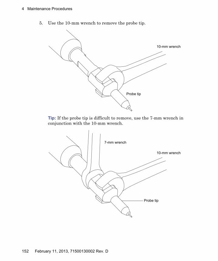
4 Maintenance Procedures
5. Use the 10-mm wrench to remove the probe tip.
Tip: If the probe tip is difficult to remove, use the 7-mm wrench in conjunction with the 10-mm wrench.
Probe tip
10-mm wrench
Probe tip
7-mm wrench
10-mm wrench
152 February 11, 2013, 71500130002 Rev. D

Replacing the ESI probe sample capillary
6. Remove the metal gasket from the probe tip.
7. Remove the PEEK union/UNF coupling assembly and capillary from the probe.
8. Unscrew and remove the knurled collar from the UNF coupling.
9. Remove the knurled collar and conductive sleeve from the capillary.
Metal gasket
PEEK union/UNF coupling assembly
Capillary
UNF couplingPEEK union
Conductive sleeve
Knurled collarLocknut
February 11, 2013, 71500130002 Rev. D 153

4 Maintenance Procedures
10. Use the 7-mm wrench to loosen the locknut.
Tip: Use the 8-mm wrench, to steady the UNF coupling when loosening the locknut.
11. Unscrew the PEEK union from the UNF coupling (this connection is finger-tight only).
12. Remove the ferrule and PTFE liner sleeve from the capillary.
13. Remove the capillary from the UNF coupling.
14. Dispose of the capillary, PTFE liner sleeve, and ferrule in accordance with local environmental regulations.
Warning: To avoid spreading contamination, dispose of the capillary, PTFE liner sleeve, and ferrule according to local environmental regulations. They can be contaminated with biohazards or toxic materials.
Ferrule
PTFE liner sleeve
154 February 11, 2013, 71500130002 Rev. D

Replacing the ESI probe sample capillary
Installing the new capillary
Required materials
• Chemical-resistant, powder-free gloves
• Combined 2.5-mm Allen wrench and cone extraction tool
• 10-mm wrench
• Needle-nose pliers
• LC pump
• HPLC-grade (or better) 1:1 acetonitrile/water
• Capillary
• Ferrule
• Seal
• PTFE liner tube
• Conductive sleeve
• Red, PEEK tubing
• Sharp knife
To install the new capillary:
1. Use the sharp knife to cut an approximately 60 cm (24 inches) piece of red, PEEK tubing squarely (that is, perpendicular to its horizontal axis).
2. Insert one end of the red, PEEK tubing in the probe inlet connector, and screw the connector, finger-tight, into the PEEK union.
Rationale: Doing so ensures a minimum dead volume when fitting the capillary.
Warning: To avoid personal contamination with biohazards or compounds that are toxic or corrosive, and to avoid spreading contamination to uncontaminated surfaces, wear clean, chemical-resistant, powder-free gloves when working with the probe and source components.
Warning: To avoid puncture wounds, handle the probe with care; the ESI probe tip is sharp.
February 11, 2013, 71500130002 Rev. D 155

4 Maintenance Procedures
3. Fit the UNF coupling to the new capillary.
4. Use the needle-nose pliers to slide a new liner sleeve and ferrule onto the capillary.
5. Insert the capillary in the PEEK union, and ensure that it is fully seated.
6. Screw the UNF coupling into the PEEK union, finger-tight only.
7. Gently tug on the capillary, testing to ensure that it stays in place.
8. Use the 7-mm wrench to tighten the locknut against the PEEK union until the union can no longer be twisted.
9. Slide a new conductive sleeve and the knurled collar over the capillary.
10. Tighten the knurled collar to the UNF coupling.
11. Perform a leak test by attaching the free end of the PEEK tubing to an LC pump and pumping 50:50 acetonitrile/water through it, at 1 mL/min.
• If leakage occurs, disassemble and remake the connection, and repeat the leak test.
• If the backpressure on the LC pump is high, replace the capillary, and repeat the leak test.
12. When no leakage occurs and the backpressure on the LC pump is normal, disconnect the PEEK tubing from the LC pump.
Warning: To avoid high-pressure liquid jet spray, wear safety goggles when performing the leak test.
TP02671
Probe inlet connector
PEEK tubing
156 February 11, 2013, 71500130002 Rev. D

Replacing the ESI probe sample capillary
13. Remove the probe inlet connector and PEEK tubing from the PEEK union.
14. Carefully thread the capillary through the probe assembly.
15. Carefully push the PEEK union/UNF coupling assembly and capillary into the probe assembly so that the locating pin on the UNF coupling is fully engaged in the locating slot at the head of the probe assembly.
16. Fit the nebulizer adjuster knob to the PEEK union/UNF coupling assembly.
17. Finger-tighten the nebulizer adjuster knob onto the probe assembly.
18. Fit the end-cover to the probe assembly.
19. Use the combined 2.5-mm Allen wrench and cone extraction tool to fit and tighten the 3 probe end-cover retaining screws.
20. Fit the metal gasket to the probe tip.
21. Fit the probe tip over the capillary, and screw the tip onto the probe assembly.
22. Use the 10-mm wrench to tighten the probe tip.
23. Use the nebulizer adjuster knob to adjust the capillary so that it protrudes by approximately 0.5 mm from the end of the probe tip.
24. Fit the ESI probe to the source (see also “Installing the ESI probe” on page 52).
Caution: To avoid gas leakage, fully tighten the probe tip.
UNF coupling locating pin
Probe assembly locating slot
February 11, 2013, 71500130002 Rev. D 157
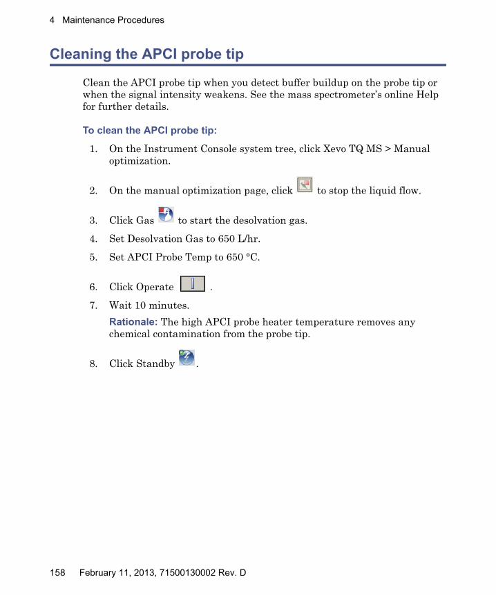
4 Maintenance Procedures
Cleaning the APCI probe tip
Clean the APCI probe tip when you detect buffer buildup on the probe tip or when the signal intensity weakens. See the mass spectrometer’s online Help for further details.
To clean the APCI probe tip:
1. On the Instrument Console system tree, click Xevo TQ MS > Manual optimization.
2. On the manual optimization page, click to stop the liquid flow.
3. Click Gas to start the desolvation gas.
4. Set Desolvation Gas to 650 L/hr.
5. Set APCI Probe Temp to 650 °C.
6. Click Operate .
7. Wait 10 minutes.
Rationale: The high APCI probe heater temperature removes any chemical contamination from the probe tip.
8. Click Standby .
158 February 11, 2013, 71500130002 Rev. D
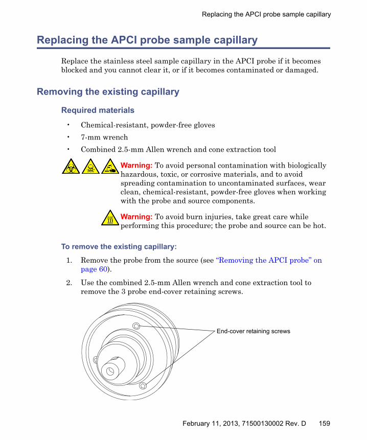
Replacing the APCI probe sample capillary
Replacing the APCI probe sample capillary
Replace the stainless steel sample capillary in the APCI probe if it becomes blocked and you cannot clear it, or if it becomes contaminated or damaged.
Removing the existing capillary
Required materials
• Chemical-resistant, powder-free gloves
• 7-mm wrench
• Combined 2.5-mm Allen wrench and cone extraction tool
To remove the existing capillary:
1. Remove the probe from the source (see “Removing the APCI probe” on page 60).
2. Use the combined 2.5-mm Allen wrench and cone extraction tool to remove the 3 probe end-cover retaining screws.
Warning: To avoid personal contamination with biologically hazardous, toxic, or corrosive materials, and to avoid spreading contamination to uncontaminated surfaces, wear clean, chemical-resistant, powder-free gloves when working with the probe and source components.
Warning: To avoid burn injuries, take great care while performing this procedure; the probe and source can be hot.
End-cover retaining screws
February 11, 2013, 71500130002 Rev. D 159
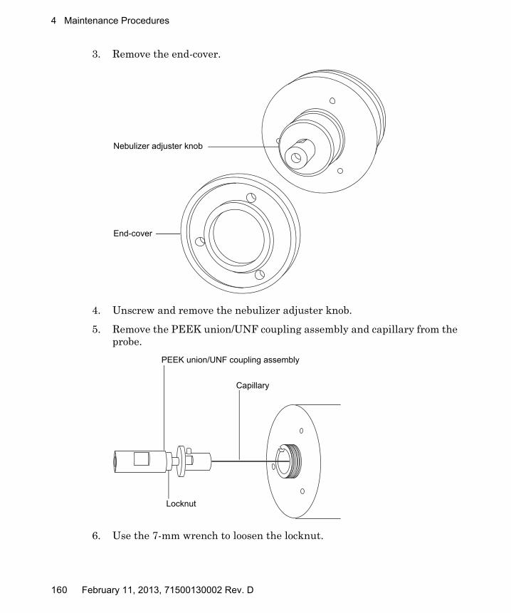
4 Maintenance Procedures
3. Remove the end-cover.
4. Unscrew and remove the nebulizer adjuster knob.
5. Remove the PEEK union/UNF coupling assembly and capillary from the probe.
6. Use the 7-mm wrench to loosen the locknut.
End-cover
Nebulizer adjuster knob
PEEK union/UNF coupling assembly
Capillary
Locknut
160 February 11, 2013, 71500130002 Rev. D

Replacing the APCI probe sample capillary
7. Unscrew the PEEK union from the UNF coupling (this connection is finger-tight).
8. Remove the ferrule from the capillary.
9. Remove the capillary from the UNF coupling.
10. Dispose of the capillary and ferrule in accordance with local environmental regulations.
Warning: To avoid spreading contamination, dispose of the capillary and ferrule according to local environmental regulations. They can be contaminated with biologically hazardous, or corrosive materials.
Ferrule
February 11, 2013, 71500130002 Rev. D 161

4 Maintenance Procedures
Installing the new capillary
Required materials
• Chemical-resistant, powder-free gloves
• Needle-nose pliers
• 7-mm wrench
• Combined 2.5-mm Allen wrench and cone extraction tool
• Red, PEEK tubing
• LC pump
• HPLC-grade (or better) 1:1 acetonitrile/water
• Capillary
• Sharp knife
To install the new capillary:
1. Use the sharp knife to cut an approximately 60 cm (24 inches) piece of red, PEEK tubing squarely (that is, perpendicular to its horizontal axis).
2. Insert one end of the red, PEEK tubing in the probe inlet connector, and screw the connector, finger-tight, into the PEEK union.
Rationale: Doing so ensures a minimum dead volume when fitting the capillary.
Warning: To avoid personal contamination with biologically hazardous, toxic, or corrosive materials, and to avoid spreading contamination to uncontaminated surfaces, wear clean, chemical-resistant, powder-free gloves when working with the probe and source components.
162 February 11, 2013, 71500130002 Rev. D

Replacing the APCI probe sample capillary
3. Fit the UNF coupling to the new capillary.
4. Use the needle-nose pliers to slide a new ferrule onto the capillary.
5. Insert the capillary in the PEEK union, and ensure that it is fully seated.
6. Screw the UNF coupling into the PEEK union, finger-tight only.
7. Gently tug on the capillary, testing to ensure that it stays in place.
8. Use the 7-mm wrench to tighten the locknut against the PEEK union.
9. Perform a leak test by attaching the free end of the PEEK tubing to an LC pump and pumping 50:50 acetonitrile/water through it at 1 mL/min.
• If leakage occurs, disassemble and remake the connection, and repeat the leak test.
• If the backpressure on the LC pump is high, replace the capillary, and repeat the leak test.
10. When no leakage occurs and the backpressure on the LC pump is normal, disconnect the PEEK tubing from the LC pump.
11. Remove the probe inlet connector and PEEK tubing from the PEEK union.
12. Remove the probe heater (see “Replacing the APCI probe heater” on page 166, step 2 through step 4).
Warning: To avoid high-pressure liquid jet spray, wear safety goggles when performing the leak test.
TP02671
Probe inlet connector
PEEK tubing
February 11, 2013, 71500130002 Rev. D 163
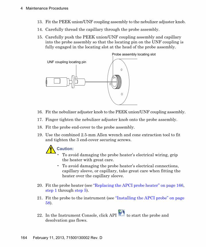
4 Maintenance Procedures
13. Fit the PEEK union/UNF coupling assembly to the nebulizer adjuster knob.
14. Carefully thread the capillary through the probe assembly.
15. Carefully push the PEEK union/UNF coupling assembly and capillary into the probe assembly so that the locating pin on the UNF coupling is fully engaged in the locating slot at the head of the probe assembly.
16. Fit the nebulizer adjuster knob to the PEEK union/UNF coupling assembly.
17. Finger tighten the nebulizer adjuster knob onto the probe assembly.
18. Fit the probe end-cover to the probe assembly.
19. Use the combined 2.5-mm Allen wrench and cone extraction tool to fit and tighten the 3 end-cover securing screws.
20. Fit the probe heater (see “Replacing the APCI probe heater” on page 166, step 1 through step 5).
21. Fit the probe to the instrument (see “Installing the APCI probe” on page 58).
22. In the Instrument Console, click API to start the probe and desolvation gas flows.
Caution:
• To avoid damaging the probe heater’s electrical wiring, grip the heater with great care.
• To avoid damaging the probe heater’s electrical connections, capillary sleeve, or capillary, take great care when fitting the heater over the capillary sleeve.
UNF coupling locating pin
Probe assembly locating slot
164 February 11, 2013, 71500130002 Rev. D

Cleaning or replacing the corona pin
Cleaning or replacing the corona pin
Required materials
• Chemical-resistant, powder-free gloves
• Needle-nose pliers
• HPLC-grade (or better) methanol
• Lint-free tissue
• Lapping film
• Corona pin
To clean or replace the corona pin:
1. Remove the corona pin from the source (see “Removing the corona pin from the source” on page 93).
2. Replace the corona pin if it is deformed or otherwise damaged. Otherwise clean its tip with the lapping film, and then wipe it clean with a methanol-saturated tissue.
3. Install the corona pin in the source (see “Installing the corona pin in the source” on page 90).
Warning: To avoid personal contamination with biologically hazardous, toxic, or corrosive materials, and to avoid spreading contamination to uncontaminated surfaces, wear clean, chemical-resistant, powder-free gloves when working with the probe and source components.
Warning: To avoid burn injuries, take great care while performing this procedure; the probe and source can be hot.
Warning: To avoid electric shock, ensure that the instrument is in Standby mode before commencing this procedure.
Warning: To avoid puncture wounds, handle the corona pin with care; the corona pin tip is sharp.
February 11, 2013, 71500130002 Rev. D 165

4 Maintenance Procedures
Replacing the APCI probe heater
Replace the APCI probe heater if it fails to heat.
Removing the APCI probe heater
Required materials
• Chemical-resistant, powder-free gloves
• Flat-blade, jeweler’s screwdriver
To remove the APCI probe heater:
1. Remove the probe from the source (see “Removing the APCI probe” on page 60).
2. Use the jeweler’s screwdriver to loosen the 2 set screws securing the probe heater cover to the probe.
Warning: To avoid personal contamination with biologically hazardous, toxic, or corrosive materials, and to avoid spreading contamination to uncontaminated surfaces, wear clean, chemical-resistant, powder-free gloves when working with the probe and source components.
Probe heater coverSet screw
166 February 11, 2013, 71500130002 Rev. D
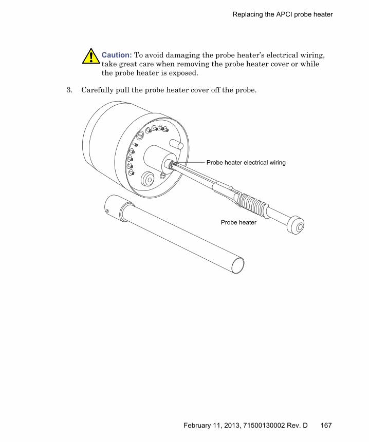
Replacing the APCI probe heater
3. Carefully pull the probe heater cover off the probe.
Caution: To avoid damaging the probe heater’s electrical wiring, take great care when removing the probe heater cover or while the probe heater is exposed.
Probe heater
Probe heater electrical wiring
February 11, 2013, 71500130002 Rev. D 167

4 Maintenance Procedures
4. Gripping the probe heater as shown, carefully pull it off the probe assembly.
5. Dispose of the probe heater in accordance with local environmental regulations.
Caution:
• To avoid damaging the probe heater’s electrical wiring, take great care when gripping and handling the heater.
• To avoid damaging the probe heater’s electrical connections, do not twist the heater when removing it from the probe assembly.
Warning: To avoid spreading contamination, dispose of the probe heater according to local environmental regulations. It can be contaminated with biohazardous, or toxic materials.
Probe heater
168 February 11, 2013, 71500130002 Rev. D
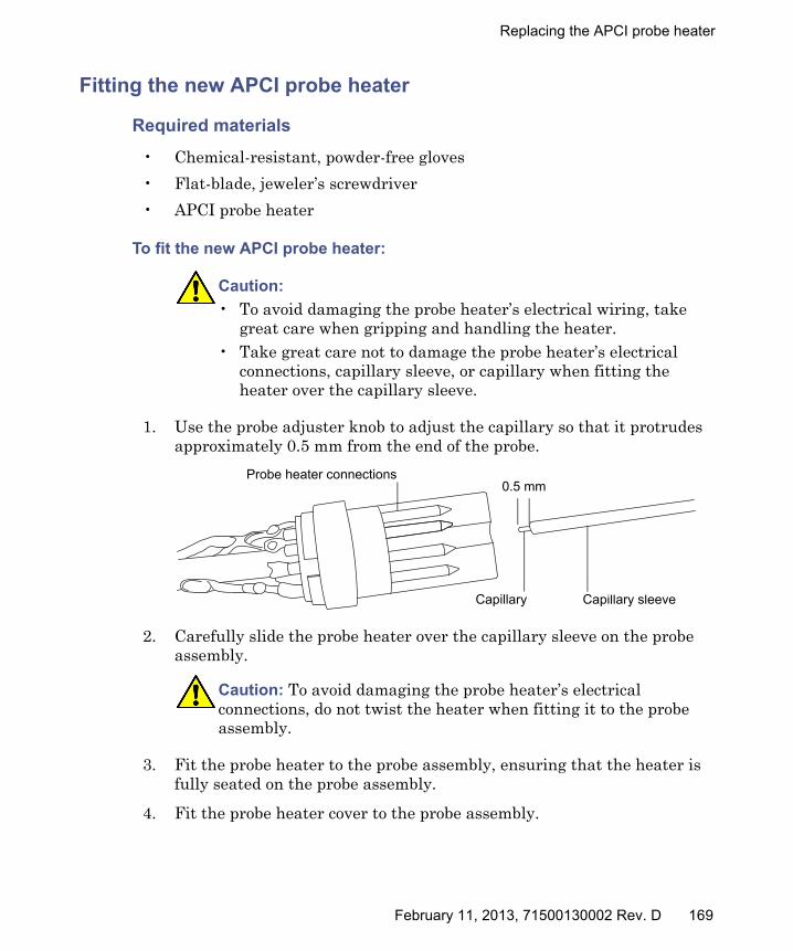
Replacing the APCI probe heater
Fitting the new APCI probe heater
Required materials
• Chemical-resistant, powder-free gloves
• Flat-blade, jeweler’s screwdriver
• APCI probe heater
To fit the new APCI probe heater:
1. Use the probe adjuster knob to adjust the capillary so that it protrudes approximately 0.5 mm from the end of the probe.
2. Carefully slide the probe heater over the capillary sleeve on the probe assembly.
3. Fit the probe heater to the probe assembly, ensuring that the heater is fully seated on the probe assembly.
4. Fit the probe heater cover to the probe assembly.
Caution:
• To avoid damaging the probe heater’s electrical wiring, take great care when gripping and handling the heater.
• Take great care not to damage the probe heater’s electrical connections, capillary sleeve, or capillary when fitting the heater over the capillary sleeve.
Caution: To avoid damaging the probe heater’s electrical connections, do not twist the heater when fitting it to the probe assembly.
TP02670
Probe heater connections
Capillary sleeveCapillary
0.5 mm
February 11, 2013, 71500130002 Rev. D 169

4 Maintenance Procedures
5. Use the jeweler’s screwdriver to tighten the 2 set screws securing the probe heater cover to the probe.
6. Fit the probe to the instrument (see “Installing the APCI probe” on page 58).
7. In the Instrument Console, click API to start the desolvation gas.
Replacing the ion block source heater
Replace the ion block source heater if it fails to heat when the instrument is pumped down (evacuated).
Required materials
• Chemical-resistant, powder-free gloves
• Needle-nose pliers
• Combined 2.5-mm Allen wrench and cone extraction tool
• Ion block source heater
To replace the ion block source heater:
1. Remove the ion block assembly from the instrument (see “Removing the ion block assembly from the source assembly” on page 120).
Warning: To avoid personal contamination with biohazards or compounds that are toxic or corrosive, and to avoid spreading contamination to uncontaminated surfaces, wear clean, chemical-resistant, powder-free gloves when working with the ion block assembly.
170 February 11, 2013, 71500130002 Rev. D
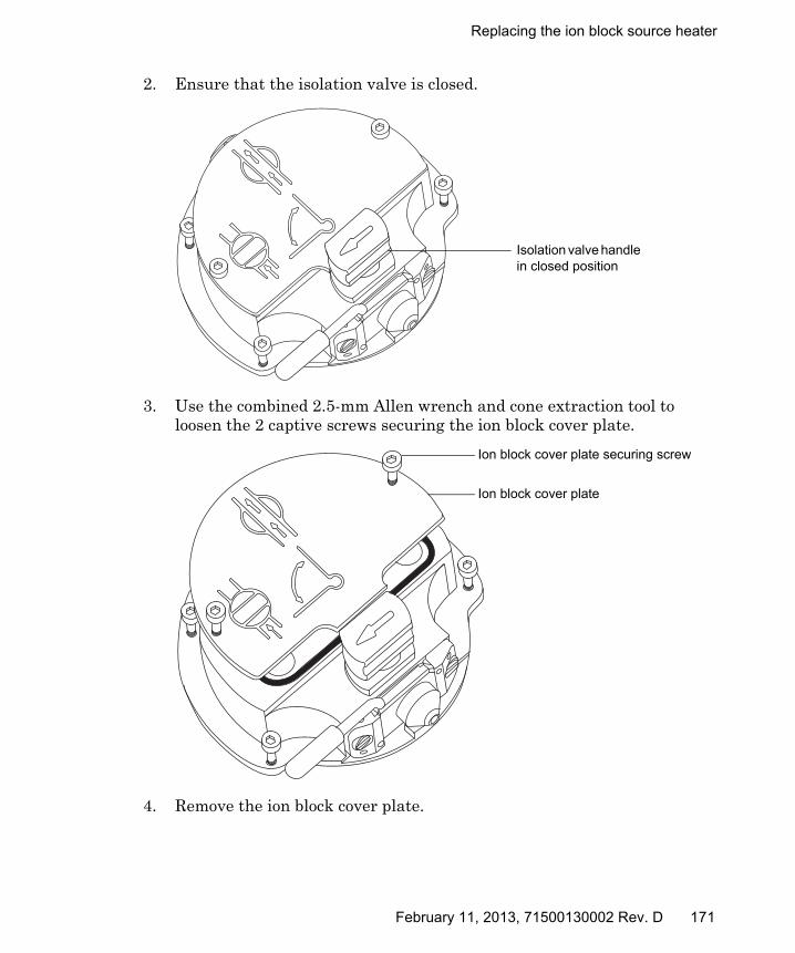
Replacing the ion block source heater
2. Ensure that the isolation valve is closed.
3. Use the combined 2.5-mm Allen wrench and cone extraction tool to loosen the 2 captive screws securing the ion block cover plate.
4. Remove the ion block cover plate.
Isolation valve handle in closed position
Ion block cover plate securing screw
Ion block cover plate
February 11, 2013, 71500130002 Rev. D 171
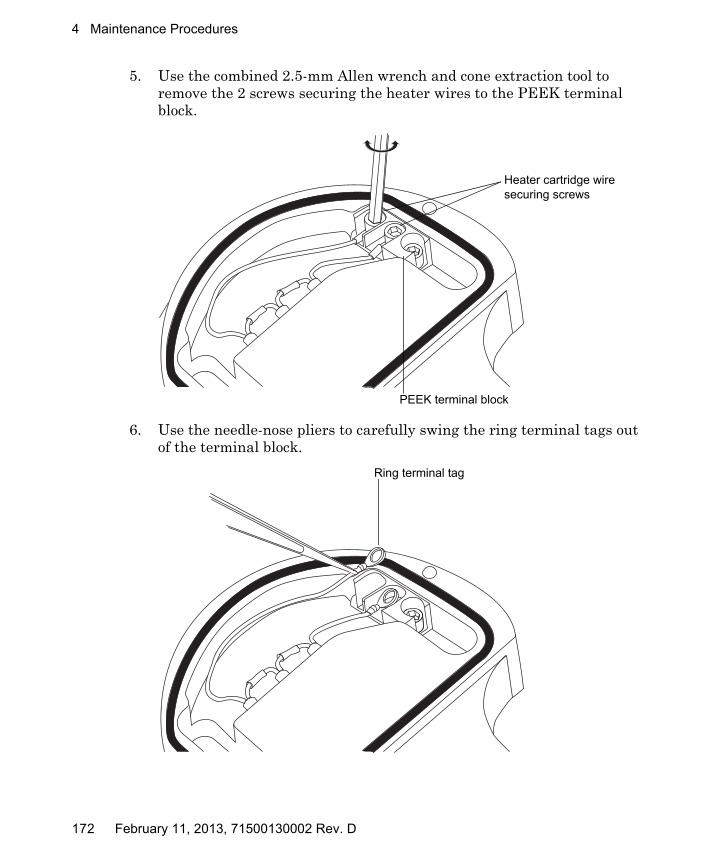
4 Maintenance Procedures
5. Use the combined 2.5-mm Allen wrench and cone extraction tool to remove the 2 screws securing the heater wires to the PEEK terminal block.
6. Use the needle-nose pliers to carefully swing the ring terminal tags out of the terminal block.
Heater cartridge wire securing screws
PEEK terminal block
Ring terminal tag
172 February 11, 2013, 71500130002 Rev. D
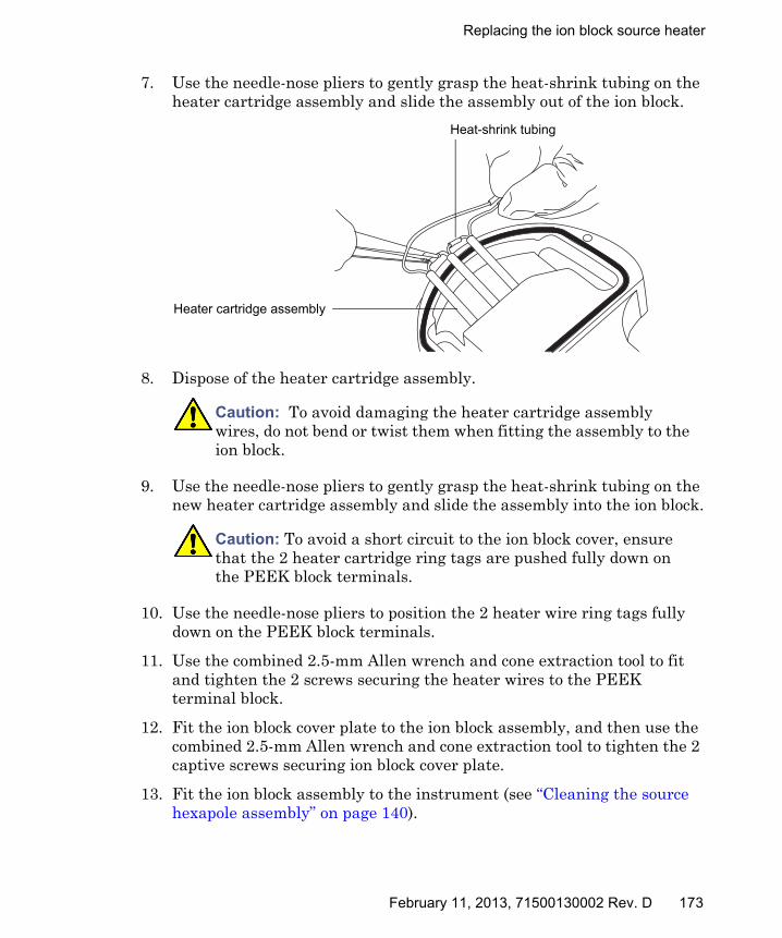
Replacing the ion block source heater
7. Use the needle-nose pliers to gently grasp the heat-shrink tubing on the heater cartridge assembly and slide the assembly out of the ion block.
8. Dispose of the heater cartridge assembly.
9. Use the needle-nose pliers to gently grasp the heat-shrink tubing on the new heater cartridge assembly and slide the assembly into the ion block.
10. Use the needle-nose pliers to position the 2 heater wire ring tags fully down on the PEEK block terminals.
11. Use the combined 2.5-mm Allen wrench and cone extraction tool to fit and tighten the 2 screws securing the heater wires to the PEEK terminal block.
12. Fit the ion block cover plate to the ion block assembly, and then use the combined 2.5-mm Allen wrench and cone extraction tool to tighten the 2 captive screws securing ion block cover plate.
13. Fit the ion block assembly to the instrument (see “Cleaning the source hexapole assembly” on page 140).
Caution: To avoid damaging the heater cartridge assembly wires, do not bend or twist them when fitting the assembly to the ion block.
Caution: To avoid a short circuit to the ion block cover, ensure that the 2 heater cartridge ring tags are pushed fully down on the PEEK block terminals.
Heat-shrink tubing
Heater cartridge assembly
February 11, 2013, 71500130002 Rev. D 173

4 Maintenance Procedures
Replacing the source assembly seals
To avoid excessive leakage of solvent vapor into the laboratory atmosphere, the following seals must be renewed at intervals of no greater than 1 year:
• Probe adjuster assembly probe seal
• Probe adjuster assembly nebulization gas seal
• Source enclosure seal
• Source enclosure nebulizer gas seal
• Source enclosure desolvation gas seal
• Source enclosure pressure test gas seal
Removing the probe adjuster assembly probe and source enclosure seals
Required materials
• Chemical-resistant, powder-free gloves
• O-ring removal kit
Warning: To avoid excessive leakage of solvent vapor into the laboratory atmosphere, the seals listed below must be renewed, at intervals of no greater than 1 year, exactly as described in this section.
174 February 11, 2013, 71500130002 Rev. D
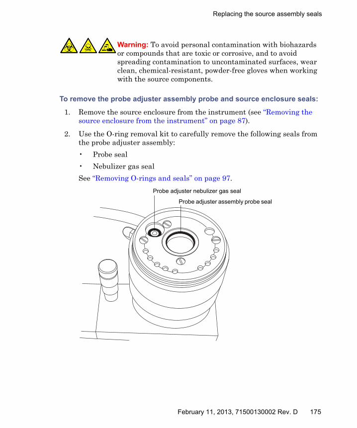
Replacing the source assembly seals
To remove the probe adjuster assembly probe and source enclosure seals:
1. Remove the source enclosure from the instrument (see “Removing the source enclosure from the instrument” on page 87).
2. Use the O-ring removal kit to carefully remove the following seals from the probe adjuster assembly:
• Probe seal
• Nebulizer gas seal
See “Removing O-rings and seals” on page 97.
Warning: To avoid personal contamination with biohazards or compounds that are toxic or corrosive, and to avoid spreading contamination to uncontaminated surfaces, wear clean, chemical-resistant, powder-free gloves when working with the source components.
Probe adjuster nebulizer gas seal
Probe adjuster assembly probe seal
February 11, 2013, 71500130002 Rev. D 175

4 Maintenance Procedures
3. Use the O-ring removal kit to carefully remove the following seals from the source enclosure:
• Source enclosure seal
• Nebulizer gas seal
• Desolvation gas seal
• Auxiliary gas seal
4. Dispose of all the seals in accordance with local environmental regulations.
Warning: To avoid spreading contamination, dispose of all the seals according to local environmental regulations. The seals can be contaminated with biohazards or toxic materials.
TP03164
Source enclosure seal
Nebulizer gas seal
Desolvation gas sealAuxiliary gas
seal
176 February 11, 2013, 71500130002 Rev. D
Replacing the source assembly seals
Fitting the new source enclosure and probe adjuster assembly probe seals
Required materials
• Chemical-resistant, powder-free gloves
• Wash bottle containing HPLC-grade (or better) 1:1 methanol/water
• New seals
To fit the new source enclosure and probe adjuster assembly probe seals:
1. Ensure that all the grooves for seals are free from dirt and debris.
Tip: If contamination is present, use 1:1 methanol/water, applied to a lint-free cloth, to carefully clean the grooves.
Requirement: Ensure that the tails of the source enclosure seals are correctly located in the groove when fitting them to the source enclosure.
2. Fit the new source enclosure seal to the source enclosure and start by feeding the seal into the groove at the bottom right-hand corner, working around the seal in a counterclockwise direction.
3. Fit the following new seals to the source enclosure:
• Nebulizer gas seal
• Desolvation gas seal
• Auxiliary gas seal
Warning: To avoid personal contamination with biohazards or compounds that are toxic or corrosive, and to avoid spreading contamination to uncontaminated surfaces, wear clean, chemical-resistant, powder-free gloves when working with the source components.
February 11, 2013, 71500130002 Rev. D 177

4 Maintenance Procedures
Requirement: These seals have a special cross-section; fit them in the groove as shown.
4. Fit the following new seals to the probe adjuster assembly:
• Probe seal
• Nebulizer gas seal
5. Refit the source enclosure to the instrument (see “Fitting the source enclosure to the instrument” on page 89).
Groove
Seal
178 February 11, 2013, 71500130002 Rev. D

Replacing the air filter
Replacing the air filter
You must replace the air filter annually.
Required materials
• Needle-nose pliers
• New filter
To replace the air filter:
1. Open the access door to the fluidics pump.
2. Unscrew the captive thumbscrew on the filter cover.
Thumbscrew
Filter cover
February 11, 2013, 71500130002 Rev. D 179

4 Maintenance Procedures
3. Remove the filter cover from the instrument.
4. Lift the filter, vertically, from the its slot in the instrument.
Tip: If necessary, use the needle-nose files to grasp the filter.
5. Dispose of the filter.
6. Fit the new filter into the instrument.
7. Fit the filter cover to the instrument.
8. Tighten the thumbscrew on the filter cover.
9. Close the access door to the fluidics pump.
Filter cover
Filter
180 February 11, 2013, 71500130002 Rev. D

APPI/APCI source—changing the UV lamp bulb
APPI/APCI source—changing the UV lamp bulb
Required materials
• Chemical-resistant, powder-free gloves
• 2.5-mm Allen wrench
• Small, Phillips® (cross-head) screwdriver
• 20-cm (8-inch) length of 4-mm nylon tube
To change the UV lamp bulb:
1. Prepare the instrument for working on the source (see “Preparing the instrument for working on the source” on page 85).
2. Pull the source enclosure release (located at the bottom, right-hand side) outwards, and swing open the enclosure.
3. Retrieve the 2.5 mm Allen wrench from its storage recess at the top, right-hand side of the source (enclosure open).
Warning: To avoid personal contamination with biologically hazardous, toxic, or corrosive materials, and to avoid spreading contamination to uncontaminated surfaces, wear clean, chemical-resistant, powder-free gloves when working with the source components.
Warning: To avoid electric shock, ensure that the instrument is suitably prepared before commencing this procedure.
Warning: To avoid burn injuries, take great care while working with the probe, source and lamp bulb; these components can be hot.
Warning: To avoid eye injury from UV radiation, ensure that the APPI lamp is off before carrying out this procedure.
February 11, 2013, 71500130002 Rev. D 181

4 Maintenance Procedures
4. Hook the short-end of the Allen wrench through the ring on the back of the bulb extraction plug, and tug to remove it.
5. Insert the length of 4-mm nylon tube through the back of the lamp drive assembly, and push the bulb forward.
TP03202
XMS0005
Nylon tube APPI lamp bulb
182 February 11, 2013, 71500130002 Rev. D
APPI/APCI source—changing the UV lamp bulb
6. Pull the bulb out of the lamp drive assembly.
7. Insert the new bulb into the lamp drive assembly.
Tip: The lamp glass is magnesium fluoride. Avoid touching it because dirt or other contaminants on the window significantly reduce UV transmission.
8. Refit the lamp-bulb access plug.
9. Close the source enclosure.
10. Slide closed the instrument’s source interface door.
Caution: To avoid breaking the bulb, do not use a screwdriver to push the bulb out of the lamp drive assembly.
February 11, 2013, 71500130002 Rev. D 183

4 Maintenance Procedures
APPI/APCI source—Cleaning the lamp window
The transmission of the high-energy photons responsible for APPI relies on the cleanliness of the magnesium fluoride lamp window. Clean the window to keep the surface clear of contamination, and thus avoid reduced sensitivity.
Required materials
• Chemical-resistant, powder-free gloves
• Lint-free cloth
• Methanol or Isopropanol
To clean the lamp window:
1. Prepare the instrument for working on the source (see “Preparing the instrument for working on the source” on page 85).
2. Pull the source enclosure release (located at the bottom, right-hand side) outwards and swing open the enclosure
3. Use methanol or isopropyl alcohol, applied to the lint-free cloth, to carefully clean the lamp window.
4. Close the source enclosure.
5. Slide closed the instrument’s source interface door.
Warning: To avoid burn injuries, take great care while working with the probe, source, and lamp bulb. These components can be hot.
Warning: To avoid eye injury from UV radiation, ensure that the APPI lamp is off before carrying out this procedure.
184 February 11, 2013, 71500130002 Rev. D
APPI/APCI source—Replacing the APPI lamp drive seals
APPI/APCI source—Replacing the APPI lamp drive seals
The following APPI lamp drive assembly O-rings must be renewed at intervals of no greater than one year:
• UV lamp bulb sealing O-ring
• Mounting shaft O-rings
• UV lamp mounting flange O-ring
Tip: An automatic pressure test is performed each time the source-enclosure is closed and when the instrument starts.
Removing the APPI lamp drive assembly seals
Required materials
• Chemical-resistant, powder-free gloves
• 2.5-mm Allen wrench (from storage recess inside the source door)
• Small Phillips (cross-head) screwdriver
• 20-cm (8-inch) length of 4-mm nylon tube
• O-ring removal kit
• The mounting-shaft insertion tool
• A suitable clear working area on a bench
• A soft cloth or mat to protect the source enclosure window as it is laid on its face
Warning: To ensure the integrity of the source exhaust system, the APPI lamp drive assembly O-rings listed below must be renewed at intervals not exceeding one year, exactly as described in this section.
February 11, 2013, 71500130002 Rev. D 185
4 Maintenance Procedures
To remove the APPI lamp drive assembly seals:
1. Remove the APCI probe and combined APPI/APCI source enclosure (see “To remove the combined APPI/APCI source:” on page 68).
2. Remove the UV bulb from the lamp drive assembly and store it safely (see “To change the UV lamp bulb:” on page 181).
3. Remove the 2 lamp-drive cover screws, above the bulb-extraction plug-aperture.
4. Clear an area, lay out the soft cloth or mat, and lay the source-enclosure on its face.
Warning: To avoid personal contamination with biologically hazardous, toxic, or corrosive materials, and to avoid spreading contamination to uncontaminated surfaces, wear clean, chemical-resistant, powder-free gloves when working with the probe and source components.
Warning: To avoid electric shock, ensure that the instrument is in Standby mode before commencing this procedure.
Caution: To avoid damaging the UV bulb, handle it with care; the bulb is fragile.
Caution: To avoid damaging the source enclosure, take care to lay it on a smooth surface. Laying the source enclosure face-first on a hard object or other protrusion can smash the glass window.
186 February 11, 2013, 71500130002 Rev. D

APPI/APCI source—Replacing the APPI lamp drive seals
5. Remove the 2 source enclosure, release-handle screws, and remove the handle.
6. Remove the remaining 2 screws, which are hidden by the release handle.
7. Slide the cover off the lamp-drive.
8. Remove the 4 source-enclosure cover screws.
9. Ease the source-enclosure cover over the lamp drive assembly.
10. Use the 2.5-mm Allen wrench to unscrew the 4 mounting-flange screws.
TP03204
4 source-enclosure cover screws
lamp-drive cover screws (2)
Release handle
February 11, 2013, 71500130002 Rev. D 187
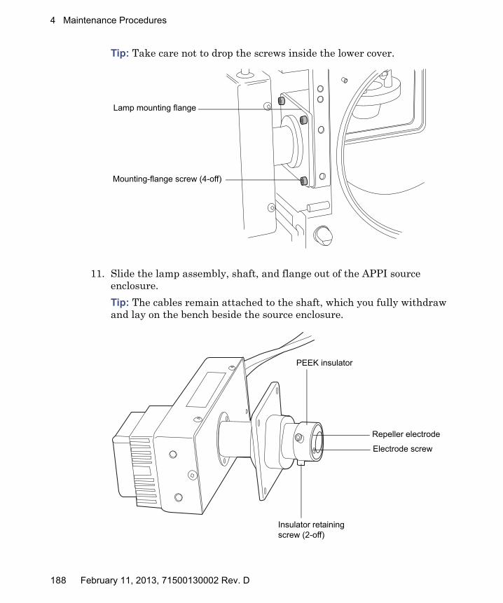
4 Maintenance Procedures
Tip: Take care not to drop the screws inside the lower cover.
11. Slide the lamp assembly, shaft, and flange out of the APPI source enclosure.
Tip: The cables remain attached to the shaft, which you fully withdraw and lay on the bench beside the source enclosure.
TP03205
Mounting-flange screw (4-off)
Lamp mounting flange
TP03206
Electrode screw
Repeller electrode
PEEK insulator
Insulator retaining screw (2-off)
188 February 11, 2013, 71500130002 Rev. D

APPI/APCI source—Replacing the APPI lamp drive seals
12. Using the small, Phillips screwdriver, remove the electrode screw and repeller electrode.
13. Use the 2.5-mm Allen wrench to remove the two insulator screws.
14. Remove the PEEK insulator from the end of the mounting shaft.
15. Slide the shaft mounting flange all the way off the shaft taking care to note the correct orientation for reassembly.
16. Use the O-ring removal kit to carefully remove the lamp-bulb sealing O-ring from inside the bulb holder (see “Removing O-rings and seals” on page 97).
17. Use the O-ring removal kit to carefully remove the two O-rings from inside the lamp mounting flange (see “Removing O-rings and seals” on page 97).
XMS0014
Lamp bulb sealing O-ring
Mounting shaft O-rings
Lamp mounting flange
February 11, 2013, 71500130002 Rev. D 189
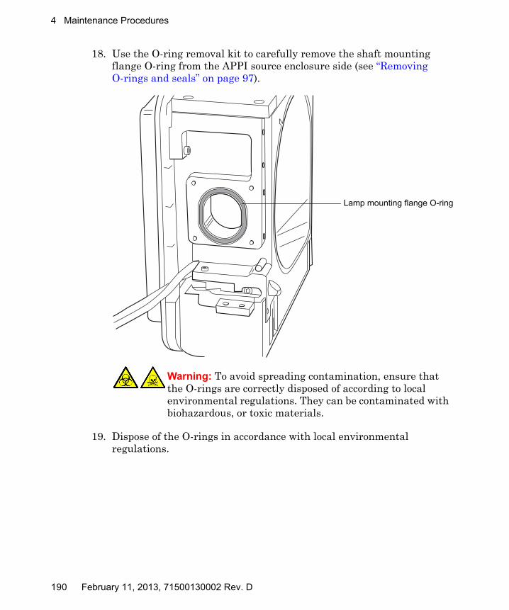
4 Maintenance Procedures
18. Use the O-ring removal kit to carefully remove the shaft mounting flange O-ring from the APPI source enclosure side (see “Removing O-rings and seals” on page 97).
19. Dispose of the O-rings in accordance with local environmental regulations.
Warning: To avoid spreading contamination, ensure that the O-rings are correctly disposed of according to local environmental regulations. They can be contaminated with biohazardous, or toxic materials.
XMS0016
Lamp mounting flange O-ring
190 February 11, 2013, 71500130002 Rev. D
APPI/APCI source—Replacing the APPI lamp drive seals
Fitting the new APPI lamp drive assembly O-rings
Required materials
• Chemical-resistant, powder-free gloves
• 2.5-mm Allen wrench
• 1:1 methanol/water
• Lint-free cloth
To fit the new APPI lamp drive assembly O-rings:
1. Ensure that all the grooves for the O-rings are free from dirt and hairs.
Tips:
• If contamination is present, use 1:1 methanol/water, applied to the lint-free cloth, to carefully clean the grooves.
• For the asymmetric O-ring seals, first seat the O-ring in the small radius at the bottom of the groove. Then use a suitable tool, one with a circular cross-section, to “roll” the remainder of the O-ring into the groove.
2. Fit the lamp bulb sealing O-ring in the lamp aperture.
3. Fit the two new O-rings inside the lamp mounting flange.
4. Fit the new lamp mounting flange O-ring to the APPI source enclosure side.
Warning: To avoid personal contamination with biologically hazardous, toxic, or corrosive materials, and to avoid spreading contamination to uncontaminated surfaces, wear clean, chemical-resistant, powder-free gloves when working with the lamp drive assembly components.
Caution: To avoid damaging the APPI lamp drive assembly O-rings, take care when fitting them. Small nicks, tears, dirt, and dust can compromise their performance, leading to rapid deterioration in the assembly’s operation.
February 11, 2013, 71500130002 Rev. D 191
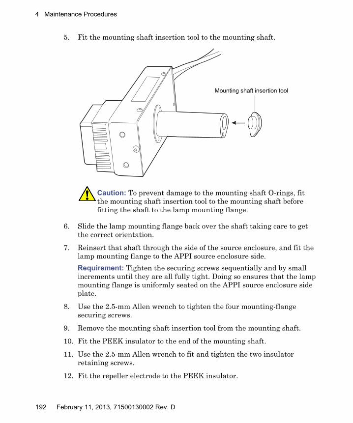
4 Maintenance Procedures
5. Fit the mounting shaft insertion tool to the mounting shaft.
6. Slide the lamp mounting flange back over the shaft taking care to get the correct orientation.
7. Reinsert that shaft through the side of the source enclosure, and fit the lamp mounting flange to the APPI source enclosure side.
Requirement: Tighten the securing screws sequentially and by small increments until they are all fully tight. Doing so ensures that the lamp mounting flange is uniformly seated on the APPI source enclosure side plate.
8. Use the 2.5-mm Allen wrench to tighten the four mounting-flange securing screws.
9. Remove the mounting shaft insertion tool from the mounting shaft.
10. Fit the PEEK insulator to the end of the mounting shaft.
11. Use the 2.5-mm Allen wrench to fit and tighten the two insulator retaining screws.
12. Fit the repeller electrode to the PEEK insulator.
Caution: To prevent damage to the mounting shaft O-rings, fit the mounting shaft insertion tool to the mounting shaft before fitting the shaft to the lamp mounting flange.
XMS0017
Mounting shaft insertion tool
192 February 11, 2013, 71500130002 Rev. D
APPI/APCI source—Replacing the APPI lamp drive seals
13. Use the small Phillips screwdriver to fit and tighten the repeller electrode retaining screw.
14. Insert the UV bulb into the lamp drive assembly and push it fully home.
15. Fully retract the lamp mounting shaft from the source enclosure.
16. Refit the lamp-assembly collar-cover, and secure it on its base with the 4 screws.
17. Refit the lamp assembly cover, and secure it on its base (2 screws) and above the bulb extraction aperture (2 screws).
18. Refit the source enclosure release handle, and secure it with the 2 screws.
19. Refit and reconnect the source-enclosure to the machine, refit the corona pin and probe. Refer to “To install the combined APPI/APCI source:” on page 66 for instructions.
February 11, 2013, 71500130002 Rev. D 193

4 Maintenance Procedures
194 February 11, 2013, 71500130002 Rev. D
A Safety Advisories
Waters® instruments and devices display hazard symbols that alert you to the hidden dangers associated with a product’s operation and maintenance. The symbols also appear in product manuals where they accompany statements describing the hazards and advising how to avoid them. This appendix presents the safety symbols and statements that apply to all of the products that Waters offers.
Contents:
Topic Page
Warning symbols.............................................................................. 196
Caution advisory .............................................................................. 200
Warnings that apply to all Waters instruments and devices ........ 201Warnings that address the replacing of fuses ................................ 206
Electrical and handling symbols ..................................................... 208
February 11, 2013, 71500130002 Rev. D 195

A Safety Advisories
Warning symbols
Warning symbols alert you to the risk of death, injury or seriously adverse physiological reactions associated with an instrument’s use or misuse. Heed all warnings when you install, repair, or operate any Waters instrument or device. Waters accepts no liability in cases of injury or property damage resulting from the failure of individuals to comply with any safety precaution when installing, repairing, or operating any of its instruments or devices.
The following symbols warn of risks that can arise when you operate or maintain a Waters instrument or device, or a component of an instrument or device. When one of these symbols appear in a manual’s narrative sections or procedures, an accompanying statement identifies the applicable risk and explains how to avoid it.
Warning: (General risk of danger. When this symbol appears on an instrument, consult the instrument’s user documentation for important safety-related information before you use the instrument.)
Warning: (Risk of burn injury from contacting hot surfaces.)
Warning: (Risk of electric shock.)
Warning: (Risk of fire.)
Warning: (Risk of sharp-point puncture injury.)
Warning: (Risk of hand crush injury.)
Warning: (Risk of exposure to ultraviolet radiation.)
Warning: (Risk of contacting corrosive substances.)
Warning: (Risk of exposure to a toxic substance.)
Warning: (Risk of personal exposure to laser radiation.)
Warning: (Risk of exposure to biological agents that can pose a serious health threat.)
196 February 11, 2013, 71500130002 Rev. D

Warning symbols
Specific warnings
The following warnings (both symbols and text) can appear in the user manuals of particular instruments and devices and on labels affixed to them or their component parts.
Burst warning
This warning applies to Waters instruments and devices fitted with nonmetallic tubing.
Warning: (Risk of tipping.)
Warning: (Risk of explosion.)
Warning: (Risk of eye injury.)
Warning: To avoid injury from bursting, nonmetallic tubing, heed these precautions when working in the vicinity of such tubing when it is pressurized:• Wear eye protection.• Extinguish all nearby flames.• Do not use tubing that is, or has been, stressed or kinked.• Do not expose nonmetallic tubing to incompatible compounds like
tetrahydrofuran (THF) and nitric or sulfuric acids.• Be aware that some compounds, like methylene chloride and
dimethyl sulfoxide, can cause nonmetallic tubing to swell, significantly reducing the pressure at which the tubing can rupture.
February 11, 2013, 71500130002 Rev. D 197

A Safety Advisories
Mass spectrometer shock hazard
The following warning applies to all Waters mass spectrometers.
The following warning applies to certain mass spectrometers when they are in Operate mode.
Mass spectrometer flammable solvents warning
This warning applies to mass spectrometers performing an analysis that requires the use of flammable solvents.
Warning: To avoid electric shock, do not remove the mass spectrometer’s protective panels. The components they cover are not user-serviceable.
Warning: To avoid nonlethal electric shock, ensure the mass spectrometer is in Standby mode before you touch any of its external surfaces that are marked with this high voltage warning symbol.
Warning: To prevent ignition of flammable solvent vapors in the enclosed space of a mass spectrometer’s ion source, ensure that nitrogen flows continuously through the source. The nitrogen supply pressure must not fall below 690 kPa (6.9 bar, 100 psi) during an analysis requiring the use of flammable solvents. Also a gas-fail device must be installed, to interrupt the flow of LC solvent should the nitrogen supply fail.
198 February 11, 2013, 71500130002 Rev. D

Warning symbols
Biohazard warning
The following warning applies to Waters instruments and devices that can process material containing biohazards, which are substances that contain biological agents capable of producing harmful effects in humans.
Biohazard and chemical hazard warning
This warning applies to Waters instruments and devices that can process biohazards, corrosive materials, or toxic materials.
Warning: To avoid infection with potentially infectious, human-sourced products, inactivated microorganisms, and other biological materials, assume that all biological fluids that you handle are infectious. Specific precautions appear in the latest edition of the US National Institutes of Health (NIH) publication, Biosafety in Microbiological and Biomedical Laboratories (BMBL).Observe Good Laboratory Practice (GLP) at all times, particularly when working with hazardous materials, and consult the biohazard safety representative for your organization regarding the proper use and handling of infectious substances.
Warning: To avoid personal contamination with biohazards, toxic materials, or corrosive materials, you must understand the hazards associated with their handling. Guidelines prescribing the proper use and handling of such materials appear in the latest edition of the National Research Council's publication, Prudent Practices in the Laboratory: Handling and Disposal of Chemicals. Observe Good Laboratory Practice (GLP) at all times, particularly when working with hazardous materials, and consult the safety representative for your organization regarding its protocols for handling such materials.
February 11, 2013, 71500130002 Rev. D 199
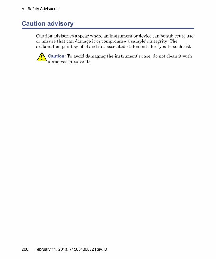
A Safety Advisories
Caution advisory
Caution advisories appear where an instrument or device can be subject to use or misuse that can damage it or compromise a sample’s integrity. The exclamation point symbol and its associated statement alert you to such risk.
Caution: To avoid damaging the instrument’s case, do not clean it with abrasives or solvents.
200 February 11, 2013, 71500130002 Rev. D

Warnings that apply to all Waters instruments and devices
Warnings that apply to all Waters instruments and devices
When operating this device, follow standard quality-control procedures and the equipment guidelines in this section.
Attention: Changes or modifications to this unit not expressly approved by the party responsible for compliance could void the user’s authority to operate the equipment.
Important: Toute modification sur cette unité n’ayant pas été expressément approuvée par l’autorité responsable de la conformité à la réglementation peut annuler le droit de l’utilisateur à exploiter l’équipement.
Achtung: Jedwede Änderungen oder Modifikationen an dem Gerät ohne die ausdrückliche Genehmigung der für die ordnungsgemäße Funktionstüchtigkeit verantwortlichen Personen kann zum Entzug der Bedienungsbefugnis des Systems führen.
Avvertenza: qualsiasi modifica o alterazione apportata a questa unità e non espressamente autorizzata dai responsabili per la conformità fa decadere il diritto all'utilizzo dell'apparecchiatura da parte dell'utente.
Atencion: cualquier cambio o modificación efectuado en esta unidad que no haya sido expresamente aprobado por la parte responsable del cumplimiento puede anular la autorización del usuario para utilizar el equipo.
注意:未經有關法規認證部門允許對本設備進行的改變或修改,可能會使使用者喪失操作該設
備的權利。
注意:未经有关法规认证部门明确允许对本设备进行的改变或改装,可能会使使用者丧失操作该设备的合法性。
주의: 규정 준수를 책임지는 당사자의 명백한 승인 없이 이 장치를 개조 또는 변경할 경우, 이 장치를 운용할 수 있는 사용자 권한의 효력을 상실할 수 있습니다.
注意:規制機関から明確な承認を受けずに本装置の変更や改造を行うと、本装置のユーザーとしての承認が無効になる可能性があります。
February 11, 2013, 71500130002 Rev. D 201

A Safety Advisories
Warning: Use caution when working with any polymer tubing under pressure:• Always wear eye protection when near pressurized polymer tubing.• Extinguish all nearby flames.• Do not use tubing that has been severely stressed or kinked.• Do not use nonmetallic tubing with tetrahydrofuran (THF) or concentrated
nitric or sulfuric acids.• Be aware that methylene chloride and dimethyl sulfoxide cause nonmetallic
tubing to swell, which greatly reduces the rupture pressure of the tubing.Attention: Manipulez les tubes en polymère sous pression avec precaution:• Portez systématiquement des lunettes de protection lorsque vous vous
trouvez à proximité de tubes en polymère pressurisés.• Eteignez toute flamme se trouvant à proximité de l’instrument.• Evitez d'utiliser des tubes sévèrement déformés ou endommagés.• Evitez d'utiliser des tubes non métalliques avec du tétrahydrofurane (THF)
ou de l'acide sulfurique ou nitrique concentré.• Sachez que le chlorure de méthylène et le diméthylesulfoxyde entraînent le
gonflement des tuyaux non métalliques, ce qui réduit considérablement leur pression de rupture.
Vorsicht: Bei der Arbeit mit Polymerschläuchen unter Druck ist besondere Vorsicht angebracht:• In der Nähe von unter Druck stehenden Polymerschläuchen stets
Schutzbrille tragen.• Alle offenen Flammen in der Nähe löschen.• Keine Schläuche verwenden, die stark geknickt oder überbeansprucht sind.• Nichtmetallische Schläuche nicht für Tetrahydrofuran (THF) oder
konzentrierte Salpeter- oder Schwefelsäure verwenden.• Durch Methylenchlorid und Dimethylsulfoxid können nichtmetallische
Schläuche quellen; dadurch wird der Berstdruck des Schlauches erheblich reduziert.
202 February 11, 2013, 71500130002 Rev. D

Warnings that apply to all Waters instruments and devices
Attenzione: fare attenzione quando si utilizzano tubi in materiale polimerico sotto pressione:• Indossare sempre occhiali da lavoro protettivi nei pressi di tubi di polimero
pressurizzati.• Spegnere tutte le fiamme vive nell'ambiente circostante.• Non utilizzare tubi eccessivamente logorati o piegati.• Non utilizzare tubi non metallici con tetraidrofurano (THF) o acido solforico
o nitrico concentrati.• Tenere presente che il cloruro di metilene e il dimetilsolfossido provocano
rigonfiamenti nei tubi non metallici, riducendo notevolmente la pressione di rottura dei tubi stessi.
Advertencia: se recomienda precaución cuando se trabaje con tubos de polímero sometidos a presión:• El usuario deberá protegerse siempre los ojos cuando trabaje cerca de tubos
de polímero sometidos a presión.• Si hubiera alguna llama las proximidades.• No se debe trabajar con tubos que se hayan doblado o sometido a altas
presiones.• Es necesario utilizar tubos de metal cuando se trabaje con tetrahidrofurano
(THF) o ácidos nítrico o sulfúrico concentrados.• Hay que tener en cuenta que el cloruro de metileno y el sulfóxido de dimetilo
dilatan los tubos no metálicos, lo que reduce la presión de ruptura de los tubos.
警告:當在有壓力的情況下使用聚合物管線時,小心注意以下幾點。
• 當接近有壓力的聚合物管線時一定要戴防護眼鏡。
• 熄滅附近所有的火焰。
• 不要使用已經被壓癟或嚴重彎曲管線。
• 不要在非金屬管線中使用四氫呋喃或濃硝酸或濃硫酸。
• 要了解使用二氯甲烷及二甲基亞楓會導致非金屬管線膨脹,大大降低管線的耐壓能力。
February 11, 2013, 71500130002 Rev. D 203
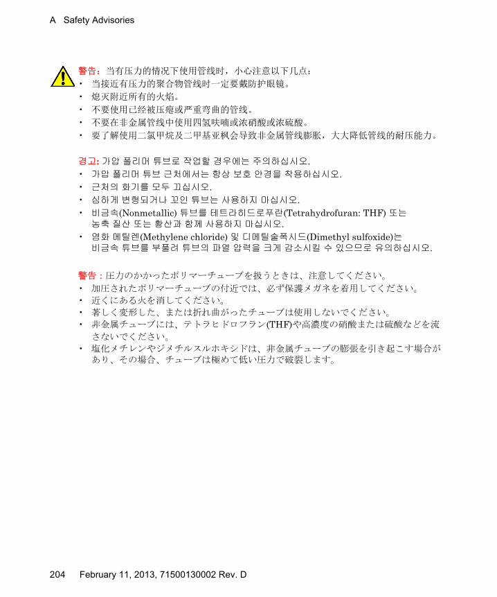
A Safety Advisories
警告:当有压力的情况下使用管线时,小心注意以下几点:
• 当接近有压力的聚合物管线时一定要戴防护眼镜。
• 熄灭附近所有的火焰。
• 不要使用已经被压瘪或严重弯曲的管线。
• 不要在非金属管线中使用四氢呋喃或浓硝酸或浓硫酸。
• 要了解使用二氯甲烷及二甲基亚枫会导致非金属管线膨胀,大大降低管线的耐压能力。
경고: 가압 폴리머 튜브로 작업할 경우에는 주의하십시오.• 가압 폴리머 튜브 근처에서는 항상 보호 안경을 착용하십시오.• 근처의 화기를 모두 끄십시오.• 심하게 변형되거나 꼬인 튜브는 사용하지 마십시오.• 비금속(Nonmetallic) 튜브를 테트라히드로푸란(Tetrahydrofuran: THF) 또는 농축 질산 또는 황산과 함께 사용하지 마십시오.
• 염화 메틸렌(Methylene chloride) 및 디메틸술폭시드(Dimethyl sulfoxide)는 비금속 튜브를 부풀려 튜브의 파열 압력을 크게 감소시킬 수 있으므로 유의하십시오.
警告:圧力のかかったポリマーチューブを扱うときは、注意してください。
• 加圧されたポリマーチューブの付近では、必ず保護メガネを着用してください。
• 近くにある火を消してください。
• 著しく変形した、または折れ曲がったチューブは使用しないでください。
• 非金属チューブには、テトラヒドロフラン(THF)や高濃度の硝酸または硫酸などを流
さないでください。
• 塩化メチレンやジメチルスルホキシドは、非金属チューブの膨張を引き起こす場合があり、その場合、チューブは極めて低い圧力で破裂します。
204 February 11, 2013, 71500130002 Rev. D

Warnings that apply to all Waters instruments and devices
Warning: The user shall be made aware that if the equipment is used in a manner not specified by the manufacturer, the protection provided by the equipment may be impaired.
Attention: L’utilisateur doit être informé que si le matériel est utilisé d’une façon non spécifiée par le fabricant, la protection assurée par le matériel risque d’être défectueuses.
Vorsicht: Der Benutzer wird darauf aufmerksam gemacht, dass bei unsachgemäßer Verwenddung des Gerätes die eingebauten Sicherheitseinrichtungen unter Umständen nicht ordnungsgemäß funktionieren.
Attenzione: si rende noto all'utente che l'eventuale utilizzo dell'apparecchiatura secondo modalità non previste dal produttore può compromettere la protezione offerta dall'apparecchiatura.
Advertencia: el usuario deberá saber que si el equipo se utiliza de forma distinta a la especificada por el fabricante, las medidas de protección del equipo podrían ser insuficientes.
警告:使用者必須非常清楚如果設備不是按照製造廠商指定的方式使用,那麼該設備所提供的保護將被消弱。
警告:使用者必须非常清楚如果设备不是按照制造厂商指定的方式使用,那么该设备所提供的保护将被削弱。
경고: 제조업체가 명시하지 않은 방식으로 장비를 사용할 경우 장비가 제공하는 보호 수단이 제대로 작동하지 않을 수 있다는 점을 사용자에게 반드시 인식시켜야 합니다.
警告: ユーザーは、製造元により指定されていない方法で機器を使用すると、機器が提供している保証が無効になる可能性があることに注意して下さい。
February 11, 2013, 71500130002 Rev. D 205
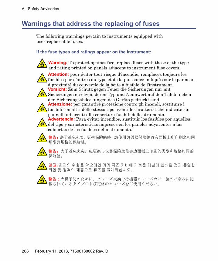
A Safety Advisories
Warnings that address the replacing of fuses
The following warnings pertain to instruments equipped with user-replaceable fuses.
If the fuse types and ratings appear on the instrument:
Warning: To protect against fire, replace fuses with those of the type and rating printed on panels adjacent to instrument fuse covers.Attention: pour éviter tout risque d'incendie, remplacez toujours les fusibles par d'autres du type et de la puissance indiqués sur le panneau à proximité du couvercle de la boite à fusible de l'instrument.Vorsicht: Zum Schutz gegen Feuer die Sicherungen nur mit Sicherungen ersetzen, deren Typ und Nennwert auf den Tafeln neben den Sicherungsabdeckungen des Geräts gedruckt sind.Attenzione: per garantire protezione contro gli incendi, sostituire i fusibili con altri dello stesso tipo aventi le caratteristiche indicate sui pannelli adiacenti alla copertura fusibili dello strumento.Advertencia: Para evitar incendios, sustituir los fusibles por aquellos del tipo y características impresos en los paneles adyacentes a las cubiertas de los fusibles del instrumento.
警告 :為了避免火災,更換保險絲時,請使用與儀器保險絲蓋旁面板上所印刷之相同類型與規格的保險絲。
警告:为了避免火灾,应更换与仪器保险丝盖旁边面板上印刷的类型和规格相同的保险丝。
경고: 화재의 위험을 막으려면 기기 퓨즈 커버에 가까운 패널에 인쇄된 것과 동일한 타입 및 정격의 제품으로 퓨즈를 교체하십시오.
警告:火災予防のために、ヒューズ交換では機器ヒューズカバー脇のパネルに記載されているタイプおよび定格のヒューズをご使用ください。
206 February 11, 2013, 71500130002 Rev. D
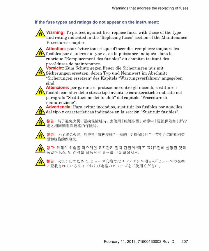
Warnings that address the replacing of fuses
If the fuse types and ratings do not appear on the instrument:
Warning: To protect against fire, replace fuses with those of the type and rating indicated in the “Replacing fuses” section of the Maintenance Procedures chapter.Attention: pour éviter tout risque d'incendie, remplacez toujours les fusibles par d'autres du type et de la puissance indiqués dans la rubrique "Remplacement des fusibles" du chapitre traitant des procédures de maintenance.Vorsicht: Zum Schutz gegen Feuer die Sicherungen nur mit Sicherungen ersetzen, deren Typ und Nennwert im Abschnitt "Sicherungen ersetzen" des Kapitels "Wartungsverfahren" angegeben sind.Attenzione: per garantire protezione contro gli incendi, sostituire i fusibili con altri dello stesso tipo aventi le caratteristiche indicate nel paragrafo "Sostituzione dei fusibili" del capitolo "Procedure di manutenzione".Advertencia: Para evitar incendios, sustituir los fusibles por aquellos del tipo y características indicados en la sección "Sustituir fusibles".
警告 :為了避免火災,更換保險絲時,應使用「維護步驟」章節中「更換保險絲」所指定之相同類型與規格的保險絲。
警告:为了避免火灾,应更换 “维护步骤 ”一章的 “更换保险丝 ”一节中介绍的相同类型和规格的保险丝。
경고: 화재의 위험을 막으려면 유지관리 절차 단원의 “퓨즈 교체” 절에 설명된 것과 동일한 타입 및 정격의 제품으로 퓨즈를 교체하십시오.
警告: 火災予防のために、ヒューズ交換ではメンテナンス項目の「ヒューズの交換」に記載されているタイプおよび定格のヒューズをご使用ください。
February 11, 2013, 71500130002 Rev. D 207
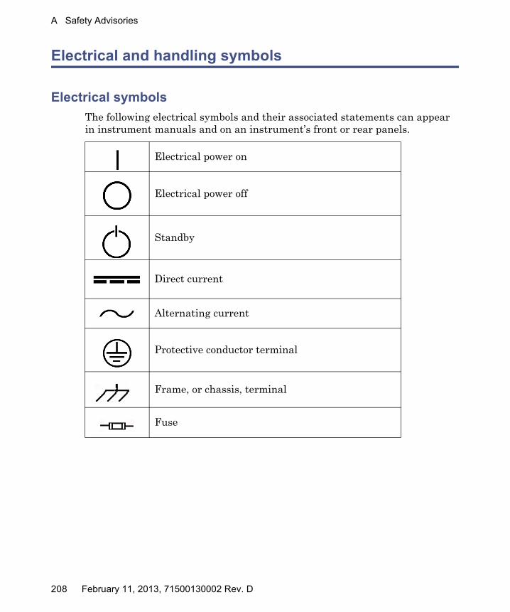
A Safety Advisories
Electrical and handling symbols
Electrical symbols
The following electrical symbols and their associated statements can appear in instrument manuals and on an instrument’s front or rear panels.
Electrical power on
Electrical power off
Standby
Direct current
Alternating current
Protective conductor terminal
Frame, or chassis, terminal
Fuse
208 February 11, 2013, 71500130002 Rev. D
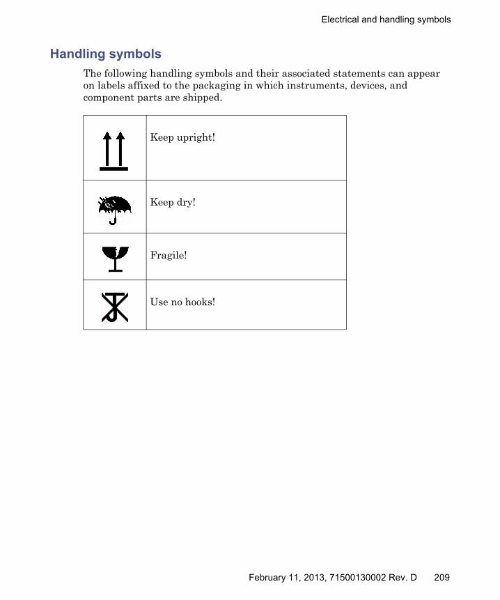
Electrical and handling symbols
Handling symbols
The following handling symbols and their associated statements can appear on labels affixed to the packaging in which instruments, devices, and component parts are shipped.
Keep upright!
Keep dry!
Fragile!
Use no hooks!
February 11, 2013, 71500130002 Rev. D 209

A Safety Advisories
210 February 11, 2013, 71500130002 Rev. D
B Materials of Construction and Compliant Solvents
Warning: To confirm the integrity of the source exhaust system, you must address any safety issues raised by the contents of this Appendix.
Contents
Topic Page
Preventing contamination ............................................................... 212
Items exposed to solvent.................................................................. 212
Solvents used to prepare mobile phases ......................................... 213
February 11, 2013, 71500130002 Rev. D 211
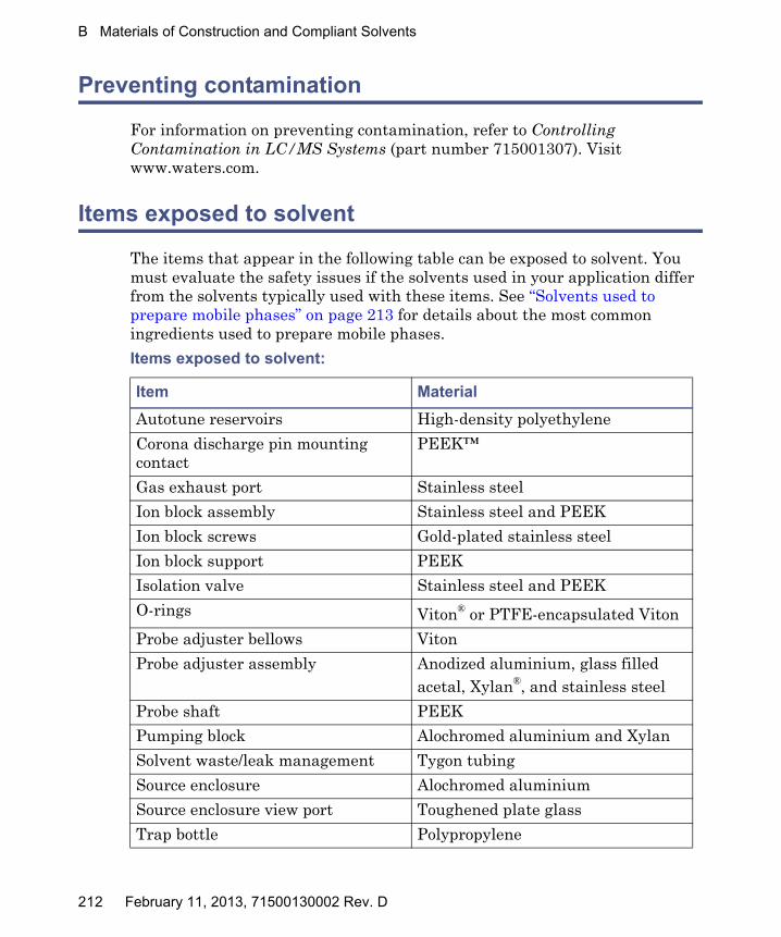
B Materials of Construction and Compliant Solvents
Preventing contamination
For information on preventing contamination, refer to Controlling Contamination in LC/MS Systems (part number 715001307). Visit www.waters.com.
Items exposed to solvent
The items that appear in the following table can be exposed to solvent. You must evaluate the safety issues if the solvents used in your application differ from the solvents typically used with these items. See “Solvents used to prepare mobile phases” on page 213 for details about the most common ingredients used to prepare mobile phases.
Items exposed to solvent:
Item Material
Autotune reservoirs High-density polyethylene
Corona discharge pin mounting contact
PEEK™
Gas exhaust port Stainless steel
Ion block assembly Stainless steel and PEEK
Ion block screws Gold-plated stainless steel
Ion block support PEEK
Isolation valve Stainless steel and PEEK
O-rings Viton® or PTFE-encapsulated Viton
Probe adjuster bellows Viton
Probe adjuster assembly Anodized aluminium, glass filled acetal, Xylan®, and stainless steel
Probe shaft PEEK
Pumping block Alochromed aluminium and Xylan
Solvent waste/leak management Tygon tubing
Source enclosure Alochromed aluminium
Source enclosure view port Toughened plate glass
Trap bottle Polypropylene
212 February 11, 2013, 71500130002 Rev. D
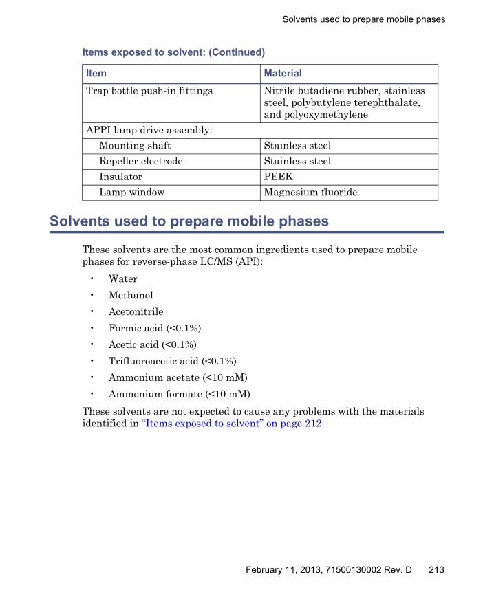
Solvents used to prepare mobile phases
Solvents used to prepare mobile phases
These solvents are the most common ingredients used to prepare mobile phases for reverse-phase LC/MS (API):
• Water
• Methanol
• Acetonitrile
• Formic acid (<0.1%)
• Acetic acid (<0.1%)
• Trifluoroacetic acid (<0.1%)
• Ammonium acetate (<10 mM)
• Ammonium formate (<10 mM)
These solvents are not expected to cause any problems with the materials identified in “Items exposed to solvent” on page 212.
Trap bottle push-in fittings Nitrile butadiene rubber, stainless steel, polybutylene terephthalate, and polyoxymethylene
APPI lamp drive assembly:
Mounting shaft Stainless steel
Repeller electrode Stainless steel
Insulator PEEK
Lamp window Magnesium fluoride
Items exposed to solvent: (Continued)
Item Material
February 11, 2013, 71500130002 Rev. D 213

B Materials of Construction and Compliant Solvents
214 February 11, 2013, 71500130002 Rev. D
C External Connections
This appendix describes the mass spectrometer’s external connections.
Warning: To avoid skeletal or muscle injury associated with lifting heavy objects, use suitable machinery and the supplied harness to lift the mass spectrometer.
Caution: To avoid damaging the mass spectrometer, observe the following precautions:• Contact Waters Technical Service before moving it.• If you must transport the instrument, or remove it from
service, contact Waters Technical Service for recommended cleaning, flushing, and packaging procedures.
See “Troubleshooting with Connections INSIGHT” on page 83.
Contents
Topic Page
External wiring and vacuum connections ...................................... 216
Connecting the Varian oil-filled roughing pump............................ 217
Connecting the Edwards oil-free roughing pump .......................... 223
Connecting to the nitrogen gas supply ........................................... 229
Connecting to the collision cell gas supply ..................................... 230
Connecting the nitrogen exhaust line............................................. 231
Connecting the liquid waste line..................................................... 234
Connecting the workstation ............................................................ 236
Connecting Ethernet cables............................................................. 237
Input/output signal connectors........................................................ 237
Connecting to the electricity source ................................................ 243
February 11, 2013, 71500130002 Rev. D 215

C External Connections
External wiring and vacuum connections
The instrument’s rear panel connectors are shown below.
Mass spectrometer rear panel connectors:
TP03118
Auxiliary
10MB/100MB
Activity
External Connections 210 1
External Connections 110 1
LA N
EPC Com Port
Video Output
Service Bus12345678910 +-
Event In 1
ExternalConnections1
Not usedC
EInterlock
OUT
+-Event In 2
Not used
- IN IN
Com
N/C
N/O
Com
N/C
N/O
12345678910 +-AnalogueO
ut
ExternalConnections2
OUT
Gas Fail
Interlock
Not used
- OUTOUT
+-Event O
ut 1
+-Event O
ut 2
OUT
Event inputs and outputs
Shielded Ethernet
Roughing pump connector
Source vacuum
Power
Nitrogen exhaustTurbo vacuum
Nitrogen inlet
Collision cell gas inlet
Pilot valve port
216 February 11, 2013, 71500130002 Rev. D

Connecting the Varian oil-filled roughing pump
Connecting the Varian oil-filled roughing pump
Note: To connect the alternative, oil-free roughing pump, see “Connecting the Edwards oil-free roughing pump” on page 223.
TP03159
Inlet port flange
Oil exhaust filter
Electrical connection panel
February 11, 2013, 71500130002 Rev. D 217

C External Connections
Required materials
• Chemical-resistant, powder-free gloves
• 7-mm nut driver
• Sharp knife
• Elbow (included in the Waters Rotary Pump Kit)
• NW25 tee (included in the installation kit)
• NW25 center rings (included in the installation kit)
• NW25 clamps (included in the installation kit)
• 12.7-mm clear PVC exhaust tubing (included in the Waters Rotary Pump Kit)
• PVC hose clamps (included in the Waters Rotary Pump Kit)
• 1-inch ID vacuum hose (included in the Waters Rotary Pump Kit)
• PTFE drip tray
218 February 11, 2013, 71500130002 Rev. D
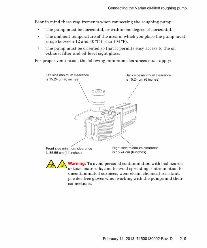
Connecting the Varian oil-filled roughing pump
Bear in mind these requirements when connecting the roughing pump:
• The pump must be horizontal, or within one degree of horizontal.
• The ambient temperature of the area in which you place the pump must range between 12 and 40 ºC (54 to 104 ºF).
• The pump must be oriented so that it permits easy access to the oil exhaust filter and oil-level sight glass.
For proper ventilation, the following minimum clearances must apply:
Warning: To avoid personal contamination with biohazards or toxic materials, and to avoid spreading contamination to uncontaminated surfaces, wear clean, chemical-resistant, powder-free gloves when working with the pumps and their connections.
TP03159
Left side minimum clearance is 15.24 cm (6 inches)
Right side minimum clearance is 15.24 cm (6 inches)
Back side minimum clearance is 15.24 cm (6 inches)
Front side minimum clearance is 35.56 cm (14 inches)
February 11, 2013, 71500130002 Rev. D 219
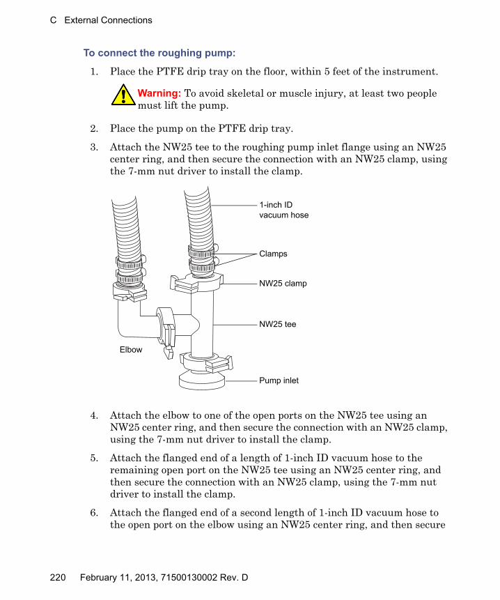
C External Connections
To connect the roughing pump:
1. Place the PTFE drip tray on the floor, within 5 feet of the instrument.
2. Place the pump on the PTFE drip tray.
3. Attach the NW25 tee to the roughing pump inlet flange using an NW25 center ring, and then secure the connection with an NW25 clamp, using the 7-mm nut driver to install the clamp.
4. Attach the elbow to one of the open ports on the NW25 tee using an NW25 center ring, and then secure the connection with an NW25 clamp, using the 7-mm nut driver to install the clamp.
5. Attach the flanged end of a length of 1-inch ID vacuum hose to the remaining open port on the NW25 tee using an NW25 center ring, and then secure the connection with an NW25 clamp, using the 7-mm nut driver to install the clamp.
6. Attach the flanged end of a second length of 1-inch ID vacuum hose to the open port on the elbow using an NW25 center ring, and then secure
Warning: To avoid skeletal or muscle injury, at least two people must lift the pump.
TP02625
Pump inlet
NW25 tee
1-inch ID vacuum hose
NW25 clamp
Clamps
Elbow
220 February 11, 2013, 71500130002 Rev. D
Connecting the Varian oil-filled roughing pump
the connection with an NW25 clamp, using the 7-mm nut driver to install the clamp.
7. Connect the free ends of the two lengths of vacuum hose to the two, 1-inch OD, straight, vacuum ports on the mass spectrometer’s rear panel.
8. Install 2 clamps on each hose end.
9. Connect the 12.7-mm clear PVC exhaust tubing to the roughing pump oil exhaust filter port NW25 nozzle fittingusing an NW25 center ring, and then secure the connection with an NW25 clamp, using the 7-mm nut driver to install the clamp.
10. Secure the exhaust tubing with a hose clamp.
11. Route the open end of the exhaust tubing to a suitable exhaust vent.
12. Inspect the oil level in the pump.
See “Inspecting the Varian roughing pump oil level” on page 101, and, if needed, “Adding oil to the Varian roughing pump” on page 102.
13. Make the electrical connections to the roughing pump.
Caution: To avoid gas leaks, use the sharp knife to cut the PVC exhaust tubing squarely (that is, perpendicular to its horizontal axis).
Caution: To prevent serious damage to the instrument, two separate exhaust systems are required: one for nitrogen, the other for the roughing pump. Vent the exhausts to atmosphere through separate lines. Oil mist can seriously damage the instrument if the nitrogen exhaust line connects with the roughing pump exhaust line. Your warranty does not cover damage caused by routing exhaust lines incorrectly.
Caution: To ensure correct operation of the roughing pump, do not operate the pump with the oil level below 30% of the MAX level.
February 11, 2013, 71500130002 Rev. D 221
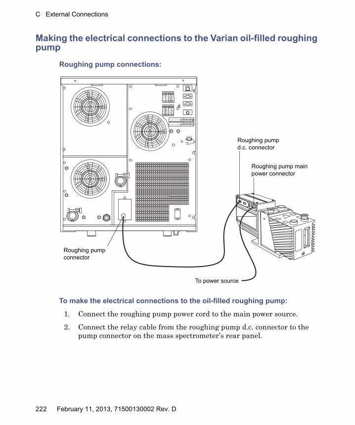
C External Connections
Making the electrical connections to the Varian oil-filled roughing pump
Roughing pump connections:
To make the electrical connections to the oil-filled roughing pump:
1. Connect the roughing pump power cord to the main power source.
2. Connect the relay cable from the roughing pump d.c. connector to the pump connector on the mass spectrometer’s rear panel.
TP03159
TP03118
Auxiliary
10MB/100MB
Activity
External Connections 210 1
External Connections 110 1
LA N
EPC Com Port
Video Output
Service Bus12345678910 +-
Event In 1
ExternalConnections1
Not usedC
EInterlock
OUT
+-Event In 2
Not used
- IN IN
Com
N/C
N/O
Com
N/C
N/O
12345678910 +-AnalogueO
ut
ExternalConnections2
OUT
Gas Fail
Interlock
Not used
- OUTOUT
+-Event O
ut 1
+-Event O
ut 2
OUT
Roughing pump main power connector
To power source
Roughing pump d.c. connector
Roughing pump connector
222 February 11, 2013, 71500130002 Rev. D

Connecting the Edwards oil-free roughing pump
Connecting the Edwards oil-free roughing pump
The oil-free roughing pump is an alternative to the oil-filled roughing pump. To connect the oil-filled roughing pump, see “Connecting the Varian oil-filled roughing pump” on page 217.
TP03165
Inlet flange
Exhaust port flange
February 11, 2013, 71500130002 Rev. D 223

C External Connections
Required materials
• Chemical-resistant, powder-free gloves
• 7-mm nut driver
• Sharp knife
• Elbow (included in the Waters Rotary Pump Kit)
• NW25 tee (included in the installation kit)
• NW25 center rings (included in the installation kit)
• NW25 clamps (included in the installation kit)
• NW40 center rings (included in the installation kit)
• NW40 clamps (included in the installation kit)
• NW25/NW40 adaptor (included in the installation kit)
• 12.7-mm clear PVC exhaust tubing (included in the Waters Rotary Pump Kit)
• PVC hose clamps (included in the Waters Rotary Pump Kit)
• 1-inch ID vacuum hose (included in the Waters Rotary Pump Kit)
224 February 11, 2013, 71500130002 Rev. D
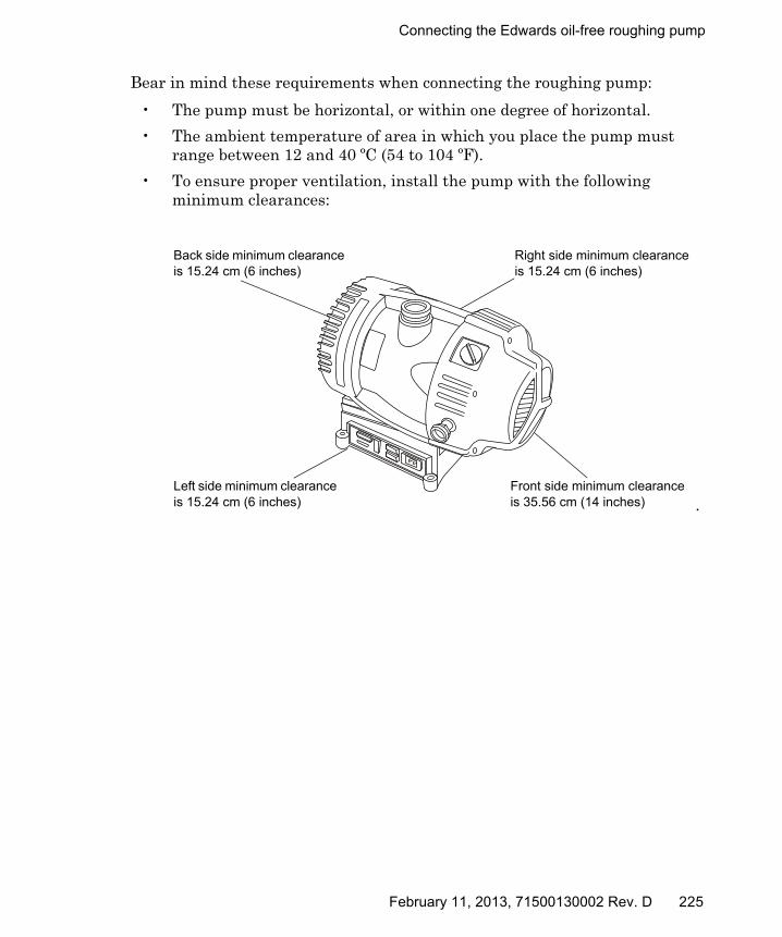
Connecting the Edwards oil-free roughing pump
Bear in mind these requirements when connecting the roughing pump:
• The pump must be horizontal, or within one degree of horizontal.
• The ambient temperature of area in which you place the pump must range between 12 and 40 ºC (54 to 104 ºF).
• To ensure proper ventilation, install the pump with the following minimum clearances:
.
TP03165Left side minimum clearance is 15.24 cm (6 inches)
Right side minimum clearance is 15.24 cm (6 inches)
Front side minimum clearance is 35.56 cm (14 inches)
Back side minimum clearance is 15.24 cm (6 inches)
February 11, 2013, 71500130002 Rev. D 225

C External Connections
To connect the oil-free roughing pump:
1. Place the pump on the floor, within 1.5 m (5 feet) of the instrument.
2. Attach the NW25/NW40 adaptor to the roughing pump inlet flange using an NW40 center ring, and then secure the connection with an NW40 clamp, using the 7-mm nut driver to install the clamp.
3. Attach the NW25 tee to the NW25/NW40 adaptor using an NW25 center ring, and then secure the connection with an NW25 clamp, using the 7-mm nut driver to install the clamp.
Warning: To avoid personal contamination with biohazards or toxic compounds, and to avoid spreading contamination to uncontaminated surfaces, wear clean, chemical-resistant, powder-free gloves when working with the pump and its connections.
Warning: To avoid skeletal or muscle injury, at least two people must lift the pump.
TP02625
NW25/NW40 adaptor
NW25 tee
1-inch ID vacuum hose
NW25 clamp
Clamps
Elbow
226 February 11, 2013, 71500130002 Rev. D
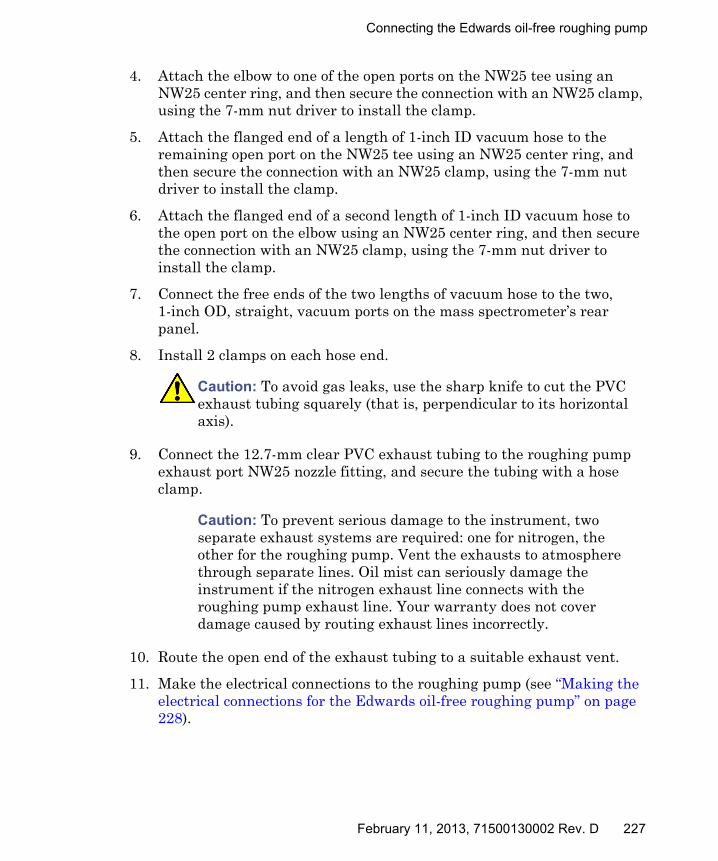
Connecting the Edwards oil-free roughing pump
4. Attach the elbow to one of the open ports on the NW25 tee using an NW25 center ring, and then secure the connection with an NW25 clamp, using the 7-mm nut driver to install the clamp.
5. Attach the flanged end of a length of 1-inch ID vacuum hose to the remaining open port on the NW25 tee using an NW25 center ring, and then secure the connection with an NW25 clamp, using the 7-mm nut driver to install the clamp.
6. Attach the flanged end of a second length of 1-inch ID vacuum hose to the open port on the elbow using an NW25 center ring, and then secure the connection with an NW25 clamp, using the 7-mm nut driver to install the clamp.
7. Connect the free ends of the two lengths of vacuum hose to the two, 1-inch OD, straight, vacuum ports on the mass spectrometer’s rear panel.
8. Install 2 clamps on each hose end.
9. Connect the 12.7-mm clear PVC exhaust tubing to the roughing pump exhaust port NW25 nozzle fitting, and secure the tubing with a hose clamp.
10. Route the open end of the exhaust tubing to a suitable exhaust vent.
11. Make the electrical connections to the roughing pump (see “Making the electrical connections for the Edwards oil-free roughing pump” on page 228).
Caution: To avoid gas leaks, use the sharp knife to cut the PVC exhaust tubing squarely (that is, perpendicular to its horizontal axis).
Caution: To prevent serious damage to the instrument, two separate exhaust systems are required: one for nitrogen, the other for the roughing pump. Vent the exhausts to atmosphere through separate lines. Oil mist can seriously damage the instrument if the nitrogen exhaust line connects with the roughing pump exhaust line. Your warranty does not cover damage caused by routing exhaust lines incorrectly.
February 11, 2013, 71500130002 Rev. D 227
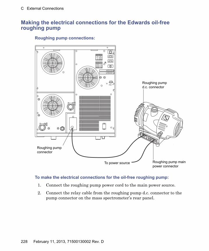
C External Connections
Making the electrical connections for the Edwards oil-free roughing pump
Roughing pump connections:
To make the electrical connections for the oil-free roughing pump:
1. Connect the roughing pump power cord to the main power source.
2. Connect the relay cable from the roughing pump d.c. connector to the pump connector on the mass spectrometer’s rear panel.
TP03118
Auxiliary
10MB/100MB
Activity
TP03165
External Connections 210 1
External Connections 110 1
LA N
EPC Com Port
Video Output
Service Bus12345678910 +-
Event In 1
ExternalConnections1
Not usedC
EInterlock
OUT
+-Event In 2
Not used
- IN IN
Com
N/C
N/O
Com
N/C
N/O
12345678910 +-AnalogueO
ut
ExternalConnections2
OUT
Gas Fail
Interlock
Not used
- OUTOUT
+-Event O
ut 1
+-Event O
ut 2
OUT
Roughing pump main power connector
To power source
Roughing pump d.c. connector
Roughing pump connector
228 February 11, 2013, 71500130002 Rev. D

Connecting to the nitrogen gas supply
Connecting to the nitrogen gas supply
Required materials
• Chemical-resistant, powder-free gloves
• 6-mm PTFE tubing (included in the Waters Rough Pump Connect Kit)
• Nitrogen regulator
To connect the nitrogen gas supply:
1. Connect one end of the 6-mm PTFE tubing to the nitrogen inlet port on the rear of the instrument.
Nitrogen and collision cell gas inlet, and vacuum connectors:
2. Attach a nitrogen regulator (not provided) to the nitrogen supply.
TP03118
Auxiliary
10MB/100MB
Activity
External Connections 210 1
External Connections 110 1
LA N
EPC Com Port
Video Output
Service Bus12345678910 +-
Event In 1
ExternalConnections1
Not usedC
EInterlock
OUT
+-Event In 2
Not used
- IN IN
Com
N/C
N/O
Com
N/C
N/O
12345678910 +-AnalogueO
ut
ExternalConnections2
OUT
Gas Fail
Interlock
Not used
- OUTOUT
+-Event O
ut 1
+-Event O
ut 2
OUT
Source vacuum
Nitrogen exhaust
Turbo vacuum
Nitrogen inlet port
Collision cell gas inlet
Pilot valve port
February 11, 2013, 71500130002 Rev. D 229

C External Connections
3. Connect the free end of the 6-mm PTFE tubing to the nitrogen regulator.
Requirement: The nitrogen must be dry and oil-free, with a purity of at least 95%.
4. Set the nitrogen regulator to 600 to 690 kPa (6.0 to 6.9 bar, 90 to 100 psi).
Connecting to the collision cell gas supply
Required materials
• Chemical-resistant, powder-free gloves
• 11-mm wrench
• 1/8-inch Swagelok® nut and ferrule
• 1/8-inch stainless steel tube (supplied with the mass spectrometer)
• Argon regulator (not supplied)
To connect the collision cell gas supply:
1. Use the 1/8-inch Swagelok nut and ferrule to connect the 1/8-inch stainless steel tube to the collision cell gas inlet on the rear of the mass spectrometer (see the figure on page 229).
2. Use the 11-mm wrench to tighten the 1/8-inch Swagelok nut.
3. Attach an argon regulator (not provided) to the argon supply.
Requirement: The argon must be dry and of high purity (99.997%).
4. Connect the free end of the tube to the collision gas supply.
5. Set the argon regulator to 50 kPa (0.5 bar, 7 psi).
230 February 11, 2013, 71500130002 Rev. D

Connecting the nitrogen exhaust line
Connecting the nitrogen exhaust line
Required materials
• Chemical-resistant, powder-free gloves
• Sharp knife
• Nitrogen exhaust trap bottle
• 6-mm, 10-mm, and 12-mm PTFE tubing (included in the Waters Rough Pump Connect Kit)
• snoop® (or equivalent) leak detector liquid
Warning: To avoid exposure to biohazards or toxic LC solvents carried in the nitrogen exhaust, ensure that the nitrogen exhaust is vented via the nitrogen exhaust trap bottle and laboratory exhaust system. The laboratory exhaust system must provide a minimum vacuum of 0.20 kPa (2 mbar, 0.03 psi) below atmospheric pressure (negative pressure).
Warning: To avoid personal contamination with biohazards or toxic compounds, and to avoid spreading contamination to uncontaminated surfaces, wear clean, chemical-resistant, powder-free gloves when working with the exhaust connections.
Warning: To avoid the buildup of hazardous gases, do not place the nitrogen exhaust trap bottle in an enclosed cabinet.
Caution: To prevent serious damage to the instrument, two separate exhaust systems are required: one for nitrogen, the other for the roughing pump. Vent the exhausts to atmosphere through separate exhaust lines. Oil mist can seriously damage the instrument if the nitrogen exhaust line connects with the roughing pump exhaust line. Your warranty does not cover damage caused by routing exhaust lines incorrectly.
February 11, 2013, 71500130002 Rev. D 231
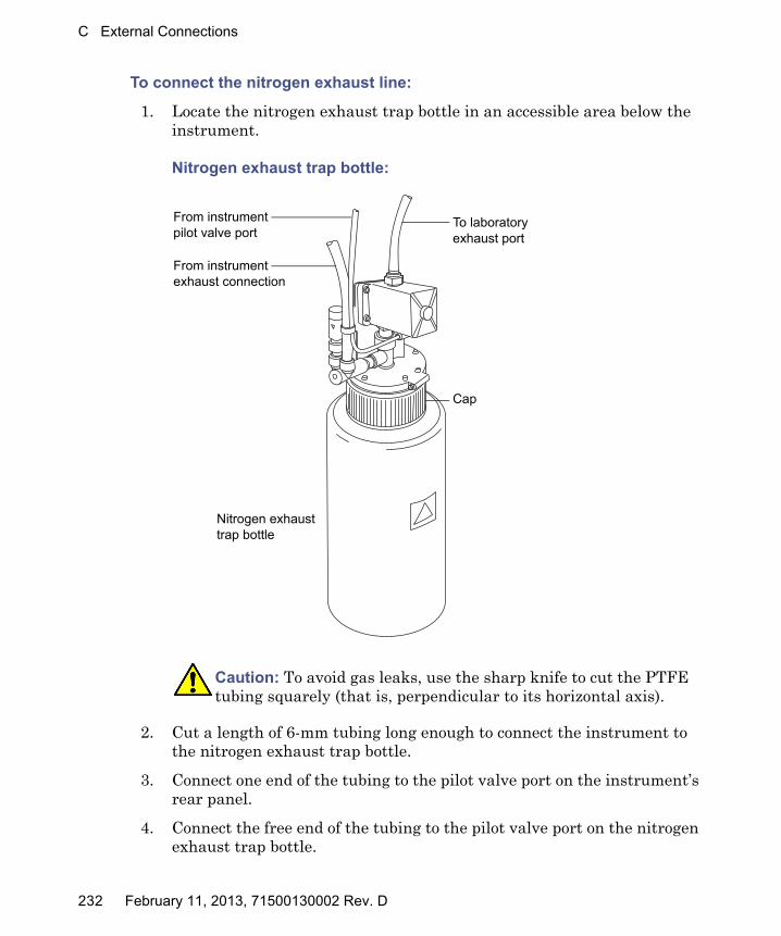
C External Connections
To connect the nitrogen exhaust line:
1. Locate the nitrogen exhaust trap bottle in an accessible area below the instrument.
Nitrogen exhaust trap bottle:
2. Cut a length of 6-mm tubing long enough to connect the instrument to the nitrogen exhaust trap bottle.
3. Connect one end of the tubing to the pilot valve port on the instrument’s rear panel.
4. Connect the free end of the tubing to the pilot valve port on the nitrogen exhaust trap bottle.
Caution: To avoid gas leaks, use the sharp knife to cut the PTFE tubing squarely (that is, perpendicular to its horizontal axis).
TP03164
From instrument exhaust connection
To laboratory exhaust port
Cap
Nitrogen exhaust trap bottle
From instrument pilot valve port
232 February 11, 2013, 71500130002 Rev. D
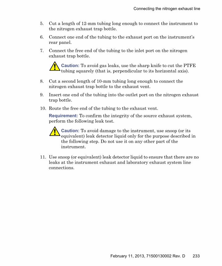
Connecting the nitrogen exhaust line
5. Cut a length of 12-mm tubing long enough to connect the instrument to the nitrogen exhaust trap bottle.
6. Connect one end of the tubing to the exhaust port on the instrument’s rear panel.
7. Connect the free end of the tubing to the inlet port on the nitrogen exhaust trap bottle.
8. Cut a second length of 10-mm tubing long enough to connect the nitrogen exhaust trap bottle to the exhaust vent.
9. Insert one end of the tubing into the outlet port on the nitrogen exhaust trap bottle.
10. Route the free end of the tubing to the exhaust vent.
Requirement: To confirm the integrity of the source exhaust system, perform the following leak test.
11. Use snoop (or equivalent) leak detector liquid to ensure that there are no leaks at the instrument exhaust and laboratory exhaust system line connections.
Caution: To avoid gas leaks, use the sharp knife to cut the PTFE tubing squarely (that is, perpendicular to its horizontal axis).
Caution: To avoid damage to the instrument, use snoop (or its equivalent) leak detector liquid only for the purpose described in the following step. Do not use it on any other part of the instrument.
February 11, 2013, 71500130002 Rev. D 233

C External Connections
Connecting the liquid waste line
Required materials
• Chemical-resistant, powder-free gloves
• Waste container
To connect the liquid waste line:
1. Place a suitable waste container below the mass spectrometer.
2. Slide a drain line over the barbed fitting of the drain (located at the bottom, left-hand side of the mass spectrometer).
Warning: To prevent personal contamination with biohazards or toxic materials, always wear chemical-resistant, powder-free gloves while performing this procedure. The waste line and connection can be contaminated.
Caution: To avoid distorting the drip tray or causing the drain cup to leak, restrain the drain cup when attaching or removing the waste line.
TP02684
Drain cup
Barbed fittingDrain line
234 February 11, 2013, 71500130002 Rev. D
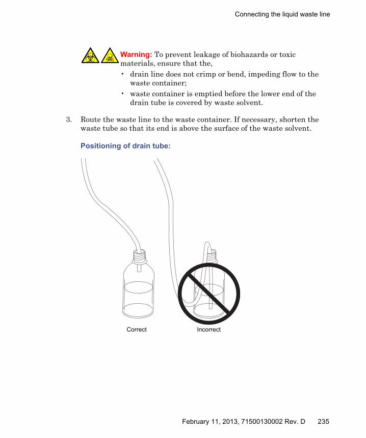
Connecting the liquid waste line
3. Route the waste line to the waste container. If necessary, shorten the waste tube so that its end is above the surface of the waste solvent.
Positioning of drain tube:
Warning: To prevent leakage of biohazards or toxic materials, ensure that the,• drain line does not crimp or bend, impeding flow to the
waste container;• waste container is emptied before the lower end of the
drain tube is covered by waste solvent.
TP01807Correct Incorrect
February 11, 2013, 71500130002 Rev. D 235

C External Connections
Connecting the workstation
Before connecting the workstation to the instrument, set up the workstation according to its accompanying instructions. Locate the workstation within 5 meters (16 feet) of the instrument.
Requirement: Use shielded network cables with the mass spectrometer to ensure compliance with FCC limits.
To connect the workstation:
1. Connect the monitor to the PC.
2. Connect one end of the shielded network cable to the appropriate port on the rear panel of the mass spectrometer.
3. Connect the other end of the shielded network cable to the port labeled instrument LAN on the workstation rear panel.
To connect the instrument to the power source:
Requirement: Do not connect the instrument’s power supply cord until you complete the installation procedures in the previous sections.
1. Select the appropriate power cord for your location.
2. Connect the female end of the power cord to the power port on the rear panel of the instrument.
Warning: To avoid injury from electric shock or fire, and to prevent damage to the workstation and ancillary equipment, do not place objects filled with liquid—such as solvent bottles—on these items, or expose them to dripping or splashing liquids.
236 February 11, 2013, 71500130002 Rev. D

Connecting Ethernet cables
Connecting Ethernet cables
Requirement: Use shielded network cables with the mass spectrometer to ensure compliance with FCC limits.
To make Ethernet connections:
1. Connect one end of one shielded Ethernet cable to the network switch, and then connect the other end to the Ethernet card on the preconfigured ACQUITY® workstation.
Tip: On preconfigured systems, the Ethernet card is identified as the Instrument LAN card.
2. Connect one end of the other shielded Ethernet cable to the back of the mass spectrometer, and then connect the other end to the network switch.
Input/output signal connectors
Two removable connectors (designated External Connections 1and External Connections 2) are on the mass spectrometer’s rear panel; these connectors hold the screw terminals for input/output signals. The connectors are keyed so that they can receive a signal cable inserted only one way.
Warning: To avoid electric shock, all electrical connections to the rear panel must be separated from hazardous voltages by double or reinforced insulation. Circuits of this type are classified as safety extra low voltage (SELV). Examples of circuits that are typically SELV include contact closure inputs and outputs for auto-samplers, and UV, RI, and fluorescence mass spectrometer signal outputs for LC/MS systems. The electrical connections on the rear panel of this mass spectrometer are all SELV.
Caution: To avoid damaging the instrument,• never apply a voltage to the Analog (out) connectors; these are
active connections driven by the instrument.• do not apply voltages higher than those shown in the tables on
page 239.
February 11, 2013, 71500130002 Rev. D 237
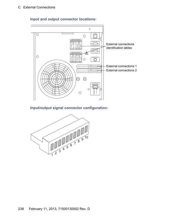
C External Connections
Input and output connector locations:
Input/output signal connector configuration:
External Connections 210 1
External Connections 110 1
LA N
EPC Com Port
Video Output
System Activity
Service Bus12345678910 +-
EventIn 1
ExternalConnections1
Not usedC
EInterlock
OUT
+-EventIn 2
Not used
- IN IN
Com
N/C
N/O
Com
N/C
N/O
12345678910 +-AnalogueO
ut
ExternalConnections2
OUT
Gas Fail
Interlock
Not used
- OUTOUT
+-Event O
ut 1
+-Event O
ut 2
OUT
External connections 1
External connections identification tables
External connections 2
12
34
56
78
910
238 February 11, 2013, 71500130002 Rev. D
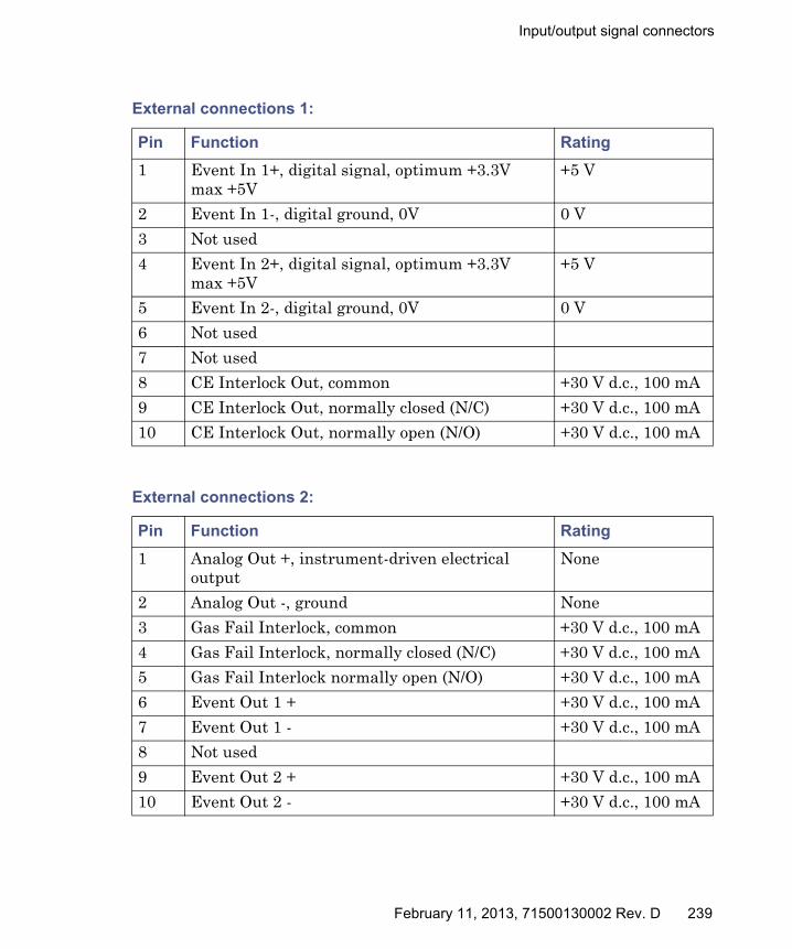
Input/output signal connectors
External connections 1:
Pin Function Rating
1 Event In 1+, digital signal, optimum +3.3V max +5V
+5 V
2 Event In 1-, digital ground, 0V 0 V
3 Not used
4 Event In 2+, digital signal, optimum +3.3V max +5V
+5 V
5 Event In 2-, digital ground, 0V 0 V
6 Not used
7 Not used
8 CE Interlock Out, common +30 V d.c., 100 mA
9 CE Interlock Out, normally closed (N/C) +30 V d.c., 100 mA
10 CE Interlock Out, normally open (N/O) +30 V d.c., 100 mA
External connections 2:
Pin Function Rating
1 Analog Out +, instrument-driven electrical output
None
2 Analog Out -, ground None
3 Gas Fail Interlock, common +30 V d.c., 100 mA
4 Gas Fail Interlock, normally closed (N/C) +30 V d.c., 100 mA
5 Gas Fail Interlock normally open (N/O) +30 V d.c., 100 mA
6 Event Out 1 + +30 V d.c., 100 mA
7 Event Out 1 - +30 V d.c., 100 mA
8 Not used
9 Event Out 2 + +30 V d.c., 100 mA
10 Event Out 2 - +30 V d.c., 100 mA
February 11, 2013, 71500130002 Rev. D 239

C External Connections
Making signal connections
Requirement: To meet the regulatory requirements of immunity from external electrical disturbances, install connection covers over the signal connectors.
To make signal connections:
1. Determine the signal connection location from the silk-screened label on the rear panel of each instrument.
Mass spectrometer signal connections:
Signal connections Description
Analog (Out) Used for analog chart output functionality. The output voltage range is 0 to 2 V. The resolution of the voltage output is 12 bits.
Gas Fail Interlock (Out)
Used to stop the solvent flow if the nitrogen gas supply fails. Maximum 30 V, 0.5 A, 10 W.
Event (Out) Allows the mass spectrometer to trigger an external event.
Event (In) Allows an external device to start data acquisition. Maximum 30 V.
CE Interlock Interfaces with a capillary electrophoresis power supply so that the instrument is safely interlocked against high voltages.
240 February 11, 2013, 71500130002 Rev. D

Input/output signal connectors
2. Attach the positive and negative leads of the signal cable to the connector.
3. Slide the clamp (with the bend facing down) into the protective shield.
4. Insert the clamp and shield (with the bend facing down) into the connection cover, and loosely tighten with one self-tapping screw.
TP02585
Signal cable
Connector
TP02586
Connection cover
Shield
Clamp
February 11, 2013, 71500130002 Rev. D 241

C External Connections
5. Insert the connector with the signal cable into the connection cover, and position the clamp over the cable leads, and tighten the clamp into place with the second self-tapping screw.
6. Place the second connection cover over the first cover, and snap it into place.
TP02587
Cable leads
Clamp
TP02588
Signal connector
Connection cover
242 February 11, 2013, 71500130002 Rev. D

Connecting to the electricity source
Connecting to the electricity source
The mass spectrometer requires a separate, grounded electricity source. The ground connection in the electrical outlet must be common and connected near the system.
Recommendation: Use a line conditioner or an uninterruptible power supply (UPS) for optimum long-term input voltage stability.
To connect to the electricity source:
1. Connect the female end of the power cord to the receptacle on the rear panel of the mass spectrometer.
2. Connect the male end of the mass spectrometer power cord to a suitable 200 to 240 V a.c. wall outlet.
Warning: To avoid electrical shock, use the SVT-type power cord in the United States and HAR-type (or better) in Europe. The main power cord must only be replaced with one of adequate rating. For information regarding what cord to use in other countries, contact your local Waters distributor.
February 11, 2013, 71500130002 Rev. D 243

C External Connections
244 February 11, 2013, 71500130002 Rev. D

D Plumbing the IntelliStart Fluidics System
This appendix provides reference information for replacing the tubing in the IntelliStart™ Fluidics system.
Warning: To avoid personal contamination with biohazards or toxic materials, always wear chemical-resistant, powder-free gloves while working on the IntelliStart Fluidics system.
Contents
Topic Page
Preventing contamination ............................................................... 246
Plumbing schematic......................................................................... 246
Pipe specifications............................................................................ 247
February 11, 2013, 71500130002 Rev. D 245
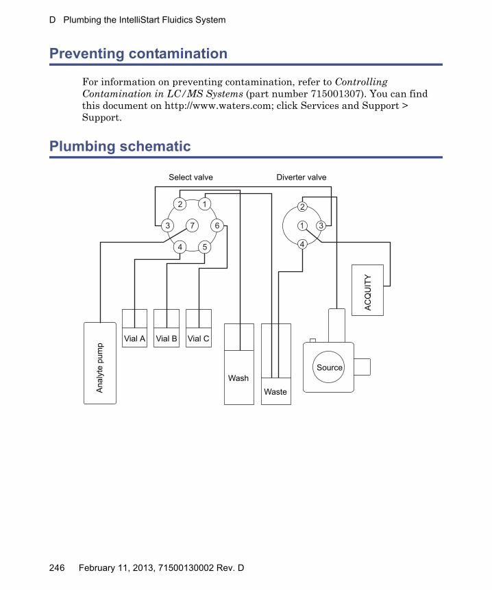
D Plumbing the IntelliStart Fluidics System
Preventing contamination
For information on preventing contamination, refer to Controlling Contamination in LC/MS Systems (part number 715001307). You can find this document on http://www.waters.com; click Services and Support > Support.
Plumbing schematic
2 1
7 63
4 5
2
1 3
4
Select valve Diverter valve
SourceA
CQ
UIT
Y
Waste
Wash
Vial A Vial B Vial C
Ana
lyte
pum
p
246 February 11, 2013, 71500130002 Rev. D

Pipe specifications
Pipe specifications
The following table gives the internal dimensions (ID), external dimensions (ED), Color, Length, and Quantity for the IntelliStart Fluidics pipes.
Replacement pipe specifications:
Connection ID (inches) ED (inches) Color Length (mm) Quantity
Select to divert 0.005 1/16 Red 200 1
Vial 0.020 1/16 Orange 600 3
Wash 0.020 1/16 Orange 1000 1
Pump 0.040 1/16 Natural 500 1
Waste 0.040 1/16 Natural 1000 2
February 11, 2013, 71500130002 Rev. D 247

D Plumbing the IntelliStart Fluidics System
248 February 11, 2013, 71500130002 Rev. D