Embed Size (px)
Citation preview

Water Wash Hood, Dry Grease Extractor
Maintenance Manual 2002
___________________________ Spring Air Systems Inc., Oakville, Ontario
Phone (905) 338-2999, Fax (905) 338-0179, [email protected] www.springairsystems.com
_____________________________________________________________________________________________ Spring Air Systems Water Wash Hood Maintenance Manual 2002
1
Water Wash Hood Dry Extractor
OPERATING AND MAINTENANCE MANUAL
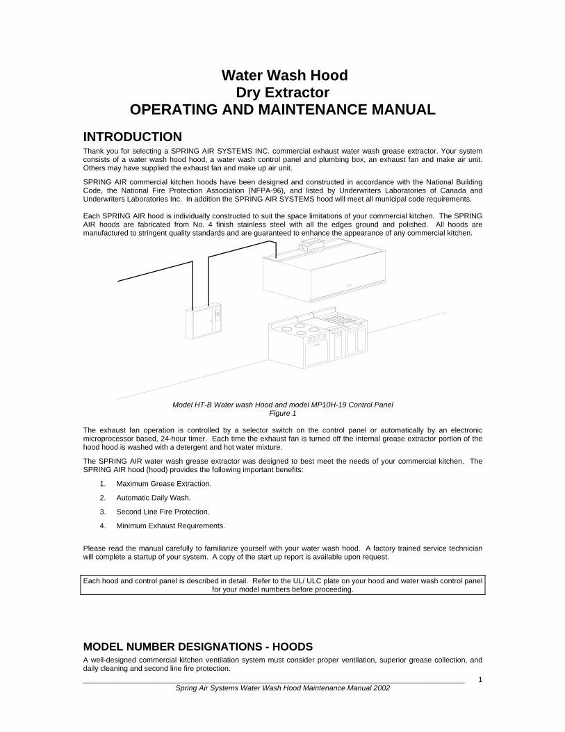
INTRODUCTION Thank you for selecting a SPRING AIR SYSTEMS INC. commercial exhaust water wash grease extractor. Your system consists of a water wash hood hood, a water wash control panel and plumbing box, an exhaust fan and make air unit. Others may have supplied the exhaust fan and make up air unit.
SPRING AIR commercial kitchen hoods have been designed and constructed in accordance with the National Building Code, the National Fire Protection Association (NFPA-96), and listed by Underwriters Laboratories of Canada and Underwriters Laboratories Inc. In addition the SPRING AIR SYSTEMS hood will meet all municipal code requirements. Each SPRING AIR hood is individually constructed to suit the space limitations of your commercial kitchen. The SPRING AIR hoods are fabricated from No. 4 finish stainless steel with all the edges ground and polished. All hoods are manufactured to stringent quality standards and are guaranteed to enhance the appearance of any commercial kitchen.
Model HT-B Water wash Hood and model MP10H-19 Control Panel
Figure 1 The exhaust fan operation is controlled by a selector switch on the control panel or automatically by an electronic microprocessor based, 24-hour timer. Each time the exhaust fan is turned off the internal grease extractor portion of the hood hood is washed with a detergent and hot water mixture.
The SPRING AIR water wash grease extractor was designed to best meet the needs of your commercial kitchen. The SPRING AIR hood (hood) provides the following important benefits:
1. Maximum Grease Extraction.
2. Automatic Daily Wash.
3. Second Line Fire Protection.
4. Minimum Exhaust Requirements.
Please read the manual carefully to familiarize yourself with your water wash hood. A factory trained service technician will complete a startup of your system. A copy of the start up report is available upon request.
Each hood and control panel is described in detail. Refer to the UL/ ULC plate on your hood and water wash control panel
for your model numbers before proceeding.
MODEL NUMBER DESIGNATIONS - HOODS A well-designed commercial kitchen ventilation system must consider proper ventilation, superior grease collection, and daily cleaning and second line fire protection.
_____________________________________________________________________________________________ Spring Air Systems Water Wash Hood Maintenance Manual 2002
2
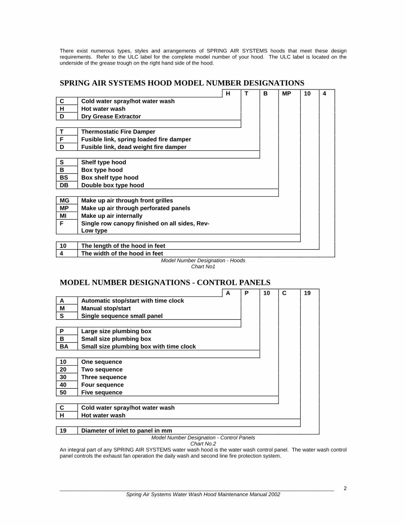
There exist numerous types, styles and arrangements of SPRING AIR SYSTEMS hoods that meet these design requirements. Refer to the ULC label for the complete model number of your hood. The ULC label is located on the underside of the grease trough on the right hand side of the hood.
SPRING AIR SYSTEMS HOOD MODEL NUMBER DESIGNATIONS H T B MP 10 4 C Cold water spray/hot water wash H Hot water wash D Dry Grease Extractor T Thermostatic Fire Damper F Fusible link, spring loaded fire damper D Fusible link, dead weight fire damper S Shelf type hood B Box type hood BS Box shelf type hood DB Double box type hood MG Make up air through front grilles MP Make up air through perforated panels MI Make up air internally F Single row canopy finished on all sides, Rev-
Low type
10 The length of the hood in feet 4 The width of the hood in feet
Model Number Designation - Hoods Chart No1
MODEL NUMBER DESIGNATIONS - CONTROL PANELS A P 10 C 19 A Automatic stop/start with time clock M Manual stop/start S Single sequence small panel P Large size plumbing box B Small size plumbing box BA Small size plumbing box with time clock 10 One sequence 20 Two sequence 30 Three sequence 40 Four sequence 50 Five sequence C Cold water spray/hot water wash H Hot water wash 19 Diameter of inlet to panel in mm
Model Number Designation - Control Panels Chart No.2
An integral part of any SPRING AIR SYSTEMS water wash hood is the water wash control panel. The water wash control panel controls the exhaust fan operation the daily wash and second line fire protection system.

_____________________________________________________________________________________________ Spring Air Systems Water Wash Hood Maintenance Manual 2002
3
CONTROL PANEL OPERATION
Sequence of Operation: All panels Exhaust fan: To start the exhaust fan rotate the fan selector switch to the “ON” position. The green “FAN ON” pilot and exhaust fan will turn on. The exhaust fan starter coil is energized through terminals 3 and 4 in the water wash control panel.
Supply fan: Power is provided for a fresh air motorized shut off damper through terminals 4, 8, & 9. The damper motor is energized through terminals 4, & 8. Once an end switch closes 120V/1/60 power is supplied back to the control panel through terminal 9. The supply fan motor starter is then energized through terminals 4 & 9.
When a motorized damper with end switch is not used in the installation the field electrician must jumper terminals 8 & 9 in the water wash panel to provide 120V/1/60 power to the supply fan motor starter.
MP10C & MP10H Wash Panel Figure 2 Cold Water Spray Panels (SB10C/MPx0C/APx0C)
When the fan selector switch is rotated to the “ON” position the cold water spray solenoid valve is energized. The cold-water spray operates while the exhaust fan is operating. The cold-water spray can be observed by looking into the inlet slot of the grease extractor. All nozzles should be spraying to form a uniformed water pattern along the length of the hood.
To stop the exhaust and supply fan rotate the selector switch to the “OFF” position. The green fan “ON” pilot and the exhaust fan will turn off.
Cold Water Spray Panels (SB10C/MPx0C/APx0C).
In addition the cold-water spray solenoid valve will close.
SINGLE SEQUENCE WASH MODEL: SB10C, SB10H CAPACITY: One ¾” (19 mm) to 1.25” (32 mm) hot water inlet and one ¾” (19 mm) to 1.25” (32 mm) hot water outlet connections for washing p to 46 ft. (14 m) of hood.
Model SB10C and SB10H control panel internal wiring
Figure 3 MODELS: MP10C, MP10H CAPACITY: One ¾” (19 mm) to 1.5” (38 mm) hot water inlet and one ¾” (19 mm) to 1.5” (38 mm) hot water outlet connections for washing up to 50 ft. (15 m) of hood.

_____________________________________________________________________________________________ Spring Air Systems Water Wash Hood Maintenance Manual 2002
4
When the selector switch has been rotated to the “OFF” position, after a 60 second time delay, the blue “WASH” pilot the detergent pump and hot water solenoid valve are energized. The hot water and detergent mixture flow to the hood and enter the grease extractor through an inlet pipe connected to the spray manifold. The detergent water mixture is sprayed from nozzles spaced uniformly along the length of the wash manifold washing the grease dirt and lint from the grease extractor baffle and into the drain. The wash continues for the period of time set on the wash timer adjustable from 0 to 600 seconds. At the end of the wash cycle the blue “WASH” pilot, the detergent pump and the hot water solenoid valve shut off. The system remains idle until the next time the fan selector switch is turned to the “ON” position.
Single Sequence Wash MP10C & MP10H Electrical Wiring Figure 4
TWO SEQUENCE WASH MODELS: MP20C, MP20H CAPACITY: One ¾” (19 mm to 1.5” (38 mm) hot water inlet and two ¾” (19 mm) to 1.5” (38 mm) hot water outlet connections for washing up to 100 ft. (30 m) of hood.
When the fan selector switch has been rotated to the “OFF” position, after a 60 second delay, the blue “WASH #1” pilot, the detergent pump, and the hot water solenoid #1 are energized.
The detergent and water mixture washes the first group of hoods (up to 50-ft. (15 m)). The wash cycle remains on for the length of time set on wash timer #1 (T1) adjustable from 0 to 600 seconds. At the end of wash cycle #1 the “WASH #1” pilot and the hot water solenoid #1 shut off and the blue “WASH #2”
MP20C & MP20H water wash panel Figure 5
_____________________________________________________________________________________________ Spring Air Systems Water Wash Hood Maintenance Manual 2002
5
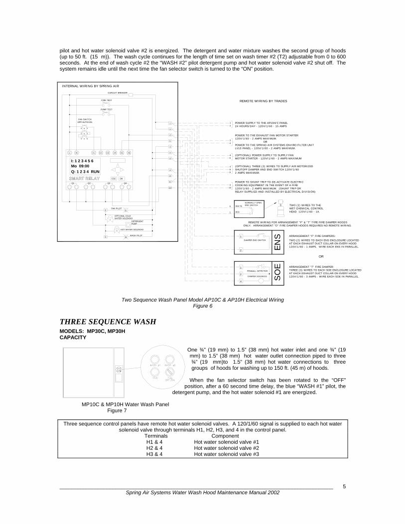
pilot and hot water solenoid valve #2 is energized. The detergent and water mixture washes the second group of hoods (up to 50 ft. (15 m)). The wash cycle continues for the length of time set on wash timer #2 (T2) adjustable from 0 to 600 seconds. At the end of wash cycle #2 the “WASH #2” pilot detergent pump and hot water solenoid valve #2 shut off. The system remains idle until the next time the fan selector switch is turned to the “ON” position.
Two Sequence Wash Panel Model AP10C & AP10H Electrical Wiring Figure 6
THREE SEQUENCE WASH MODELS: MP30C, MP30H CAPACITY
One ¾” (19 mm) to 1.5” (38 mm) hot water inlet and one ¾” (19 mm) to 1.5” (38 mm) hot water outlet connection piped to three ¾” (19 mm)to 1.5” (38 mm) hot water connections to three groups of hoods for washing up to 150 ft. (45 m) of hoods.
When the fan selector switch has been rotated to the “OFF” position, after a 60 second time delay, the blue “WASH #1” pilot, the
detergent pump, and the hot water solenoid #1 are energized.
MP10C & MP10H Water Wash Panel Figure 7
Three sequence control panels have remote hot water solenoid valves. A 120/1/60 signal is supplied to each hot water solenoid valve through terminals H1, H2, H3, and 4 in the control panel.
Terminals Component H1 & 4 Hot water solenoid valve #1 H2 & 4 Hot water solenoid valve #2 H3 & 4 Hot water solenoid valve #3
OPTIONAL COLDWATER SOLENOID
HOT WATER SOLENOID
H
CFAN PILOT
WASH PILOTB
PUMPDETERGENT
G
SMART RELAY
Q: 1 2 3 4 RUN
INTERNAL WIRING BY SPRING AIR
Mo 09:00
Q1 Q2
L
I: 1 2 3 4 5 6
N I1
OFF/AUTO/ONFAN SWITCH
1
OK
Q3
ESC
Q4
I5I2 I3 I4 I6
10
9
8
4
4
4
3
5
2
CURCUIT BREAKER
PUMP TEST
FIRE TEST
1
WHITE TWO (2) WIRES TO THE5
HEAD 120V/1/60 - 1A.WET CHEMICAL CONTROL
ARRANGEMENT "F" FIRE DAMPERS:
ARRANGEMENT "T" FIRE DAMPER:
REMOTE WIRING FOR ARRANGEMENT "F" & "T" TYPE FIRE DAMPER HOODS
TWO (2) WIRES TO EACH ENS ENCLOSURE LOCATEDAT EACH EXHAUST DUCT COLLAR ON EVERY HOOD
AT EACH EXHAUST DUCT COLLAR ON EVERY HOOD
ONLY. ARRANGEMENT "D" FIRE DAMPER HOODS REQUIRES NO REMOTE WIRING.
120V/1/60 - 1 AMPS. WIRE EACH ENS IN PARALLEL.
THREE (3) WIRES TO EACH SOE ENCLOSURE LOCATED
120V/1/60 - 3 AMPS - WIRE EACH SOE IN PARALLEL.
FENWALL DETECTOR
DAMPER SOLENOID
DAMPER END SWITCH
1
2
4
2
1
1 RED
ENS
SO
E
OR
POWER TO THE SPRING AIR SYSTEMS ENVIRO FILTER UNIT
(OPTIONAL) THREE (3) WIRES TO SUPPLY AIR MOTORIZED
RELAY SUPPLIED AND INSTALLED BY ELECTRICAL DIVISION)
120V/1/60 - 2 AMPS MAXIMUM.
2 AMPS MAXIMUM.
POWER TO THE EXHAUST FAN MOTOR STARTER
LV10 PANEL - 120V/1/60 - 2 AMPS MAXIMUM.
(OPTIONAL) POWER SUPPLY TO SUPPLY FANMOTOR STARTER - 120V/1/60 - 2 AMPS MAXIMUM
SHUTOFF DAMPER AND END SWITCH 120V/1/60
POWER TO SHUNT TRIP TO DE-ACTIVATE ELECTRICCOOKING EQUIPMENT IN THE EVENT OF A FIRE120V/1/60 - 2 AMPS MAXIMUM. (SHUNT TRIP OR
NORMALLY OPENEND SWITCH
4
104
98
94
43 OR
REMOTE WIRING BY TRADES
POWER SUPPLY TO THE AP10H/C PANEL24 HOURS/DAY - 120V/1/60 - 15 AMPS
14
x x
o x
o o
o
x
x
_____________________________________________________________________________________________ Spring Air Systems Water Wash Hood Maintenance Manual 2002
6
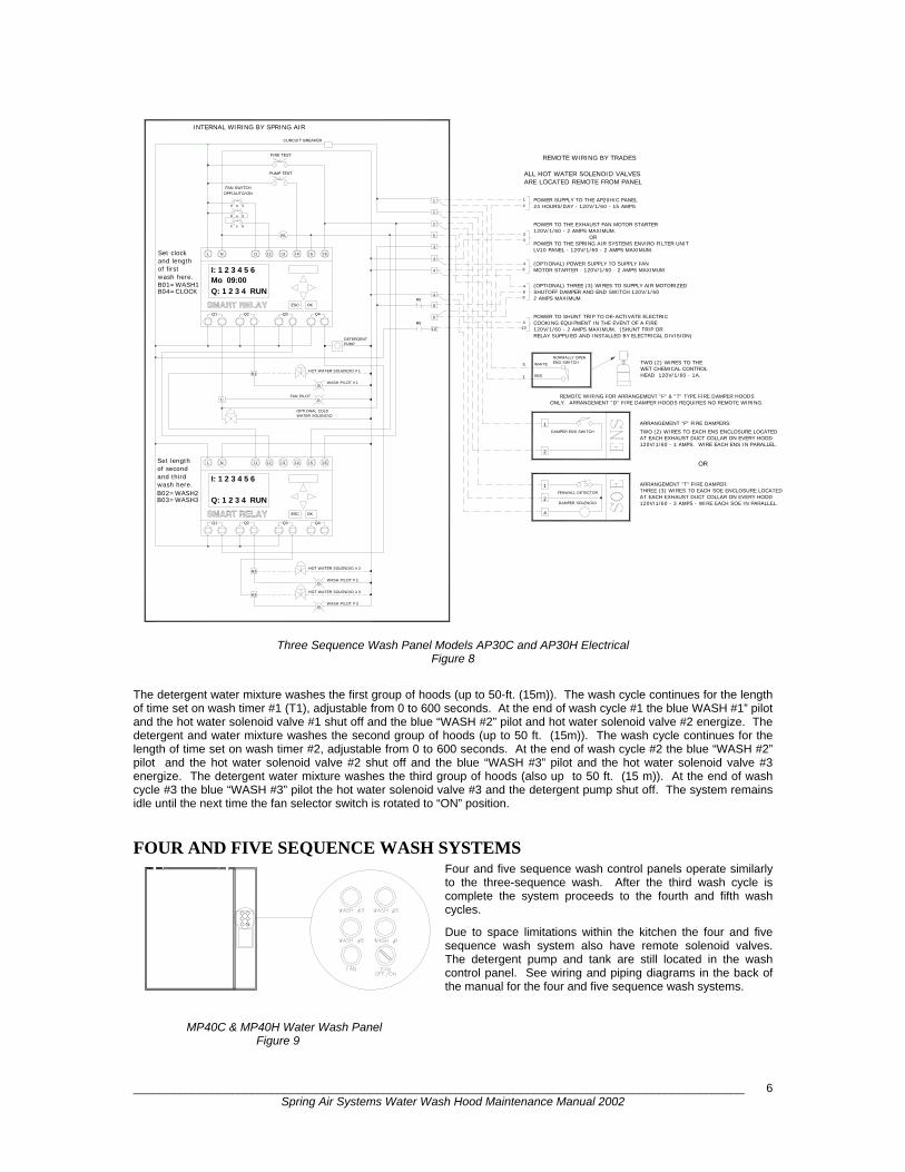
Three Sequence Wash Panel Models AP30C and AP30H Electrical
Figure 8
The detergent water mixture washes the first group of hoods (up to 50-ft. (15m)). The wash cycle continues for the length of time set on wash timer #1 (T1), adjustable from 0 to 600 seconds. At the end of wash cycle #1 the blue WASH #1” pilot and the hot water solenoid valve #1 shut off and the blue “WASH #2” pilot and hot water solenoid valve #2 energize. The detergent and water mixture washes the second group of hoods (up to 50 ft. (15m)). The wash cycle continues for the length of time set on wash timer #2, adjustable from 0 to 600 seconds. At the end of wash cycle #2 the blue “WASH #2” pilot and the hot water solenoid valve #2 shut off and the blue “WASH #3” pilot and the hot water solenoid valve #3 energize. The detergent water mixture washes the third group of hoods (also up to 50 ft. (15 m)). At the end of wash cycle #3 the blue “WASH #3” pilot the hot water solenoid valve #3 and the detergent pump shut off. The system remains idle until the next time the fan selector switch is rotated to “ON” position.
FOUR AND FIVE SEQUENCE WASH SYSTEMS Four and five sequence wash control panels operate similarly to the three-sequence wash. After the third wash cycle is complete the system proceeds to the fourth and fifth wash cycles.
Due to space limitations within the kitchen the four and five sequence wash system also have remote solenoid valves. The detergent pump and tank are still located in the wash control panel. See wiring and piping diagrams in the back of the manual for the four and five sequence wash systems.
MP40C & MP40H Water Wash Panel Figure 9
H2
H3
WASH PILOT #3
WASH PILOT #2
HOT WATER SOLENOID #3
HOT WATER SOLENOID #2
B
B
I1
Q: 1 2 3 4 RUN
SMART RELAY
INTERNAL WIRING BY SPRING AIR
I1
SMART RELAY
Q: 1 2 3 4 RUN
H1
Set length
wash here.and thirdof second
B03=WASH3B02=WASH2
Q1 Q2
I: 1 2 3 4 5 6
L N
C
NSet clock L
B01=WASH1B04=CLOCK
wash here.
and lengthof first
Q1 Q2
Mo 09:00I: 1 2 3 4 5 6
FAN SWITCHOFF/AUTO/ON
ALL HOT WATER SOLENOID VALVESARE LOCATED REMOTE FROM PANEL
POWER SUPPLY TO THE AP20H/C PANEL24 HOURS/DAY - 120V/1/60 - 15 AMPS
REMOTE WIRING BY TRADES
POWER TO THE EXHAUST FAN MOTOR STARTER120V/1/60 - 2 AMPS MAXIMUM.
LV10 PANEL - 120V/1/60 - 2 AMPS MAXIMUM.
(OPTIONAL) POWER SUPPLY TO SUPPLY FANMOTOR STARTER - 120V/1/60 - 2 AMPS MAXIMUM
SHUTOFF DAMPER AND END SWITCH 120V/1/60 2 AMPS MAXIMUM.
POWER TO SHUNT TRIP TO DE-ACTIVATE ELECTRICCOOKING EQUIPMENT IN THE EVENT OF A FIRE120V/1/60 - 2 AMPS MAXIMUM. (SHUNT TRIP OR
POWER TO THE SPRING AIR SYSTEMS ENVIRO FILTER UNIT
(OPTIONAL) THREE (3) WIRES TO SUPPLY AIR MOTORIZED
RELAY SUPPLIED AND INSTALLED BY ELECTRICAL DIVISION)
DAMPER END SWITCH
REMOTE WIRING FOR ARRANGEMENT "F" & "T" TYPE FIRE DAMPER HOODSONLY. ARRANGEMENT "D" FIRE DAMPER HOODS REQUIRES NO REMOTE WIRING.
ESC OK
Q3 Q4
I3I2 I6I4 I5
HOT WATER SOLENOID #1
WASH PILOT #1
WATER SOLENOIDOPTIONAL COLD
FAN PILOT
B
G
4
1
2
1
2
5 WHITE
RED1
I6I4I3I2 I5
ESC OK
Q3 Q4
DETERGENTPUMP
R5
FIRE TEST
PUMP TEST
8
10
9R5
4
4
R54
410
94
84
9
1
1
2
3
5
4
43
1
NORMALLY OPEN
WET CHEMICAL CONTROLTWO (2) WIRES TO THE
OR
ARRANGEMENT "F" FIRE DAMPERS:TWO (2) WIRES TO EACH ENS ENCLOSURE LOCATEDAT EACH EXHAUST DUCT COLLAR ON EVERY HOOD
ARRANGEMENT "T" FIRE DAMPER:
AT EACH EXHAUST DUCT COLLAR ON EVERY HOOD
120V/1/60 - 1 AMPS. WIRE EACH ENS IN PARALLEL.
THREE (3) WIRES TO EACH SOE ENCLOSURE LOCATED
120V/1/60 - 3 AMPS - WIRE EACH SOE IN PARALLEL.
HEAD 120V/1/60 - 1A.
FENWALL DETECTOR
DAMPER SOLENOID
END SWITCH
OR
CURCUIT BREAKER
x x o
xo x
oo x

_____________________________________________________________________________________________ Spring Air Systems Water Wash Hood Maintenance Manual 2002
7
REMOTE PIPING
All remote piping must meet applicable local plumbing codes. The panel must be installed with adequate protection to stop the flow of detergent back into the potable water supply. This may be accomplished, depending on the municipality, with a vacuum breaker and check valve assembly or a back flow preventor. SPRING AIR SYSTEMS will always prepipe the detergent line into the main hot water outlet pipe in the plumbing cabinet unless advised to do otherwise prior to shipment.
IT IS IMPORTANT TO CHECK WITH LOCAL PLUMBING INSPECTORS TO DETERMINE WHAT IS ACCEPTABLE PRACTICE IN YOUR JURISDICTION.
Backflow Preventor Vacuum Breaker Figure 10
CLEANING THE EXTERIOR Normal soil can be removed with a mild detergent water mixture applied to a cloth.
To remove baked on grease, apply a cleanser to a damp cloth or sponge and rub on the metal in the direction of the polishing lines. DO NOT RUB IN A CIRCULAR MOTION. Burnt deposits, which do not respond, can usually be removed by rubbing the surface with SCOTCH-BRITE scouring pads or STAINLESS scouring pads. Do not use ordinary steel wool. Heat tint can be removed by a vigorous scouring in the direction of the polish lines using SCOTCH-BRITE or STAINLESS scouring pads in conjunction with powdered cleanser.
Once the wash cycle(s) are complete wipe of the interior surface of the hood canopy and the underside of the grease trough and skirt.
During the wash cycle(s) condensation may form on these surfaces. The condensation will assist in cleaning off any grease, dirt or lint, which may have built up during the daily operation.
Cleaning the Hood Exterior Figure 11

_____________________________________________________________________________________________ Spring Air Systems Water Wash Hood Maintenance Manual 2002
8
WASH TIMER SETTINGS All SB10C, MP10C, MP20C, MP30C, MP40C, & MP50C wash control panel timers are factory set at two minutes. All SB10H, MP10H, MP20H, MP30H, MP40H, & MP50H wash control panel timers are factory set at three minutes. After the first four days of operation open the front access door on the grease extractor. Visually check if the baffle and interior surfaces are clean. If there are grease deposits check that the hot water pressure is between 40 psi (2.8 kg/cm2) and 70 psi (4.2 kg/cm2) and the hot water temperature is between 120 F (49 C) and 180 F (82 C). If there is adequate temperature and pressure either use a higher detergent concentration or increase the wash time. The detergent concentration can be adjusted by increasing the cam setting on the side of the detergent pump.
Loosen the wing nut on the side of the detergent pump and rotate the cam to the next setting. The cam is adjustable from 0 to 6, 6 being the highest detergent concentration. Only increase one setting at a time. Inspect the interior each day and adjust until all surfaces are clean.
Only increase the wash time in 30-second intervals until all baffles and exposed interior grease extractor surfaces are clean.
For type “C” water wash hoods check that the cold water pressure is at least 10 psi 1.4 kg/cm2).
AUTOMATIC WASH SYSTEMS:
SBA10H, SBA10C, AP10H, AP10C, AP20H, AP20C, AP30H, AP30C, AP40H, AP40C, AP50H, & AP50C
The automatic wash control panels are equipped with a solid-state microprocessor. The fan selector switch is replaced with a three-position “OFF/AUTO/ON” switch. In the “OFF” and “ON” positions the control panel operates identical to the standard SB, & MP manual wash panels. When the fan switch is rotated to the “AUTO” position the solid-state time clock controls the OFF/ON operation of the exhaust fan, supply fan and wash cycle. Setting the clock (T6) is as simple as setting a digital watch.
Automatic Wash Panel Figure 12a
SBA10C and SBA10H Automatic Wash Panel Wiring Schematic
Figure 12b
NOTE 1:ALL REMOTE ELECTRIAL WIRING
AND NATIONAL CODE REQUIREMENTSSHALL CONFORM TO ALL LOCAL
INTERNAL WIRING BY SPRING AIR
Q: 1 2 3 4 RUN
Mo 09:00I: 1 2 3 4 5 6
SMART RELAYQ1
L
Q2
N I1 I2
FAN SWITCHOFF/AUTO/ON
PUMPDETERGENT
HOT WATER SOLENOID
WASH PILOTH B
FAN PILOT
OPTIONAL COLDWATER SOLENOID
C G
ESC
Q3
OK
Q4
I3 I4 I5 I6
CURCUIT BREAKER
4
4
8
9
3
5
1
END SWITCH TWO (2) WIRES TO THE
MOTOR STARTERS OVERLOADS
5
1
RED
WHITEWET CHEMICAL CONTROLHEAD 120V/1/60 - 1A.
ELECTRICAL DIVISIONAND DISCONNECTS BY
NOTE 2:
SHUTOFF DAMPER AND END SWITCH 120V/1/60 (OPTIONAL) THREE (3) WIRES TO SUPPLY AIR MOTORIZED
MOTOR STARTER - 120V/1/60 - 2 AMPS MAXIMUM(OPTIONAL) POWER SUPPLY TO SUPPLY FAN
LV10 PANEL - 120V/1/60 - 2 AMPS MAXIMUM.POWER TO THE SPRING AIR SYSTEMS ENVIRO FILTER UNIT
POWER TO THE EXHAUST FAN MOTOR STARTER
24 HOURS/DAY - 120V/1/60 - 15 AMPSPOWER SUPPLY TO THE SB10H/C PANEL
NORMALLY OPEN
2 AMPS MAXIMUM.948
94
REMOTE WIRING BY TRADES
120V/1/60 - 2 AMPS MAXIMUM.34
41
ORx x o
xo x
oo x
_____________________________________________________________________________________________ Spring Air Systems Water Wash Hood Maintenance Manual 2002
9
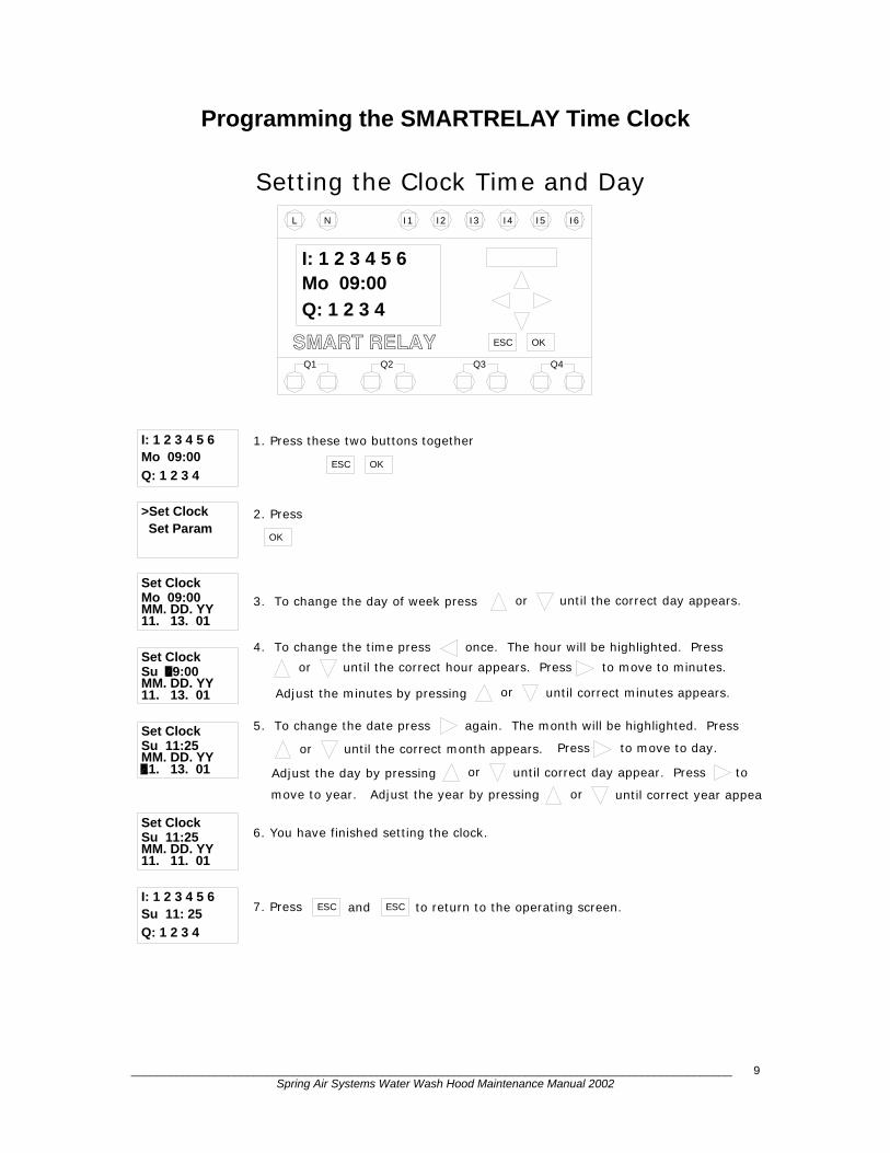
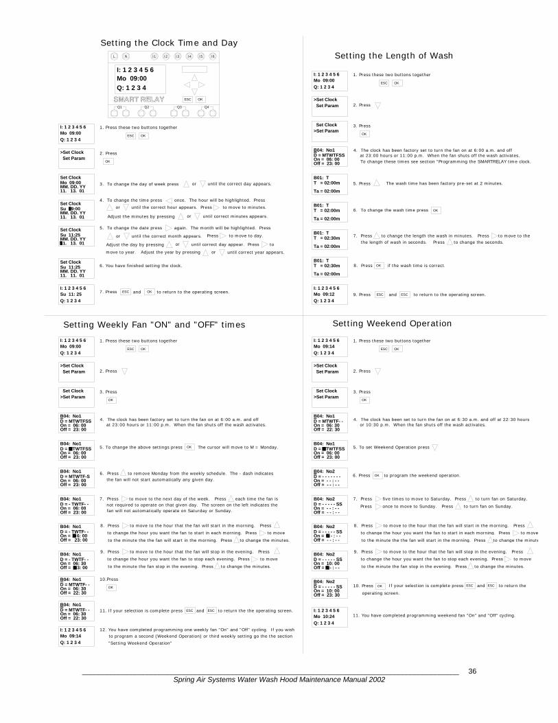
Programming the SMARTRELAY Time Clock
to return to the operating screen.
6. You have finished setting the clock.
3. To change the day of week press
move to year. Adjust the year by pressing
5. To change the date press again. The month will be highlighted. Press
until the correct month appears.
orAdjust the day by pressing
Adjust the minutes by pressing
until the correct hour appears.4. To change the time press once. The hour will be highlighted. Press
1. Press these two buttons together
Su 11: 25
Q: 1 2 3 4
I: 1 2 3 4 5 6
Su 11:25Set Clock
11. 11. 01MM. DD. YY
ESC7. Press and
Su 11:25MM. DD. YY
Set Clock
11. 13. 01
Set Clock
11. 13. 01MM. DD. YYSu 09:00
11. 13. 01MM. DD. YYMo 09:00Set Clock
Set Param>Set Clock
Q: 1 2 3 4
Mo 09:00I: 1 2 3 4 5 6
or
or
ESC
2. Press
OK
OK
until correct year appear
or until the correct day appears.
until correct day appear. Press to
Press to move to day.
until correct minutes appears.
Press to move to minutes.
or
or
I3
Setting the Clock Time and Day
I: 1 2 3 4 5 6
Q: 1 2 3 4
Mo 09:00
SMART RELAYQ1
L N
Q2
I2I1
OKESC
Q3 Q4
I5I4 I6
ESC

_____________________________________________________________________________________________ Spring Air Systems Water Wash Hood Maintenance Manual 2002
10
Setting the Weekly Fan “ON” and “OFF” Times
Mo 09:00
fan will not automatically operate on Saturday or Sunday.
the fan will not start automatically any given day.
to program a second (Weekend Operation) or third weekly setting go the the section12. You have completed programming one weekly fan "On" and "Off" cycling. If you wish
11. If your selection is complete press and to return the the operating screen.
9. Press to move to the hour that the fan will stop in the evening. Press
8. Press to move to the hour that the fan will start in the morning. Press
7. Press to move to the next day of the week. Press each time the fan is
6. Press to remove Monday from the weekly schedule. The - dash indicates
5. To change the above settings press
4. The clock has been factory set to turn the fan on at 6:00 a.m. and off
to the minute the fan stop in the evening. Press to change the minutes.
to change the hour you want the fan to stop each evening. Press to move
to the minute the the fan will start in the morning. Press to change the minutes.
to change the hour you want the fan to start in each morning. Press to move
not required to operate on that given day. The screen on the left indicates the
at 23:00 hours or 11:00 p.m. When the fan shuts off the wash activates.
Off = 23: 00
D = - TWTF- -
Mo 09:14
Q: 1 2 3 4
I: 1 2 3 4 5 6
B04: No1
On = 06: 30Off = 22: 30
Off = 22: 30On = 06: 30
B04: No1
Off = 2 3: 00On = 06: 30
B04: No1
Off = 23: 00On = 0 6: 00
B04: No1
"Setting Weekend Operation"
10.Press
OK
D = - TWTF- -
D = MTWTF-S
B04: No1
On = 06: 00
Off = 23: 00On = 06: 00
B04: No1
B04: No1D = MTWTFSSOn = 06: 00Off = 23: 00
>Set Clock Set Param
Off = 23: 00On = 06: 00D = MTWTFSSB04: No1
>Set Param Set Clock
Q: 1 2 3 4
3. Press
OK
2. Press
ESC OK
ESC ESC
The cursor will move to M = Monday.OK
1. Press these two buttons togetherI: 1 2 3 4 5 6
D = - TWTF- -
D = MTWTF- -
D = MTWTF- -
_____________________________________________________________________________________________ Spring Air Systems Water Wash Hood Maintenance Manual 2002
11
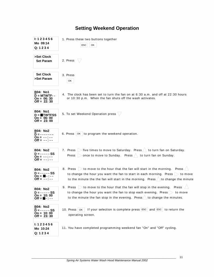
Setting Weekend Operation
>Set Clock
11. You have completed programming weekend fan "On" and "Off" cycling.
If your selection is complete press and to return the
Press once to move to Sunday. Press to turn fan on Sunday.
7. Press five times to move to Saturday. Press to turn fan on Saturday.
6. Press to program the weekend operation.
or 10:30 p.m. When the fan shuts off the wash activates.4. The clock has been set to turn the fan on at 6:30 a.m. and off at 22:30 hours
9. Press to move to the hour that the fan will stop in the evening. Press to change the hour you want the fan to stop each evening. Press to move
to the minute the fan stop in the evening. Press to change the minutes.
to the minute the the fan will start in the morning. Press to change the minute
to change the hour you want the fan to start in each morning. Press to move
8. Press to move to the hour that the fan will start in the morning. Press
Off = - - : - -
Q: 1 2 3 4
I: 1 2 3 4 5 6Mo 10:24
D = - - - - - SS
D = - - - - - SS
Off = 23: 30
B04: No2
B04: No2
On = 10: 00
Off = - - : - -On = 10: 00
OK
operating screen.
10. Press
On = - - : - -
B04: No2D = - - - - - SS
On = - - : - -Off = - - : - -
B04: No2D = - - - - - SS
Off = - - : - - On = - - : - -D = - - - - - - -B04: No2
Off = 22: 30On = 06: 30D = MTWTF- -
B04: No1D = MTWTFSSOn = 06: 00Off = 23: 00
Set Param
B04: No1
>Set Param Set Clock
OK
5. To set Weekend Operation press
2. Press
3. Press
OK
ESC ESC
1. Press these two buttons togetherMo 09:14
Q: 1 2 3 4
I: 1 2 3 4 5 6
ESC OK

_____________________________________________________________________________________________ Spring Air Systems Water Wash Hood Maintenance Manual 2002
12
Setting the Wash Cycle Length
>Set Clock
9. Press and to return to the operating screen.
8. Press if the wash time is correct.
the length of wash in seconds. Press to change the seconds.7. Press to change the length the wash in minutes. Press to move to the
The wash time has been factory pre-set at 2 minutes.
4. The clock has been factory set to turn the fan on at 6:00 a.m. and offat 23:00 hours or 11:00 p.m. When the fan shuts off the wash activates.To change these times see section "Programming the SMARTRELAY time clock.
Ta = 02:00m
Mo 09:12I: 1 2 3 4 5 6
Q: 1 2 3 4
ESC ESC
T = 02:30m
T = 02:30m
Ta = 02:00m
Ta = 02:00m
T = 02:00m
T = 02:00m
Ta = 02:00m
Set Param
Off = 23: 00On = 06: 00D = MTWTFSSB04: No1
>Set Param Set Clock
B01: T
B01: T
B01: T
B01: T5. Press
OK
6. To change the wash time press
2. Press
3. Press
OK
OK
1. Press these two buttons together
Q: 1 2 3 4
Mo 09:00I: 1 2 3 4 5 6
ESC OK
OK
I5I1
SMART RELAY
I: 1 2 3 4 5 6Mo 09:00
Q: 1 2 3 4
Q1 Q2
L N
ESC
Q3
I3I2 I4
Q4
I6
_____________________________________________________________________________________________ Spring Air Systems Water Wash Hood Maintenance Manual 2002
13
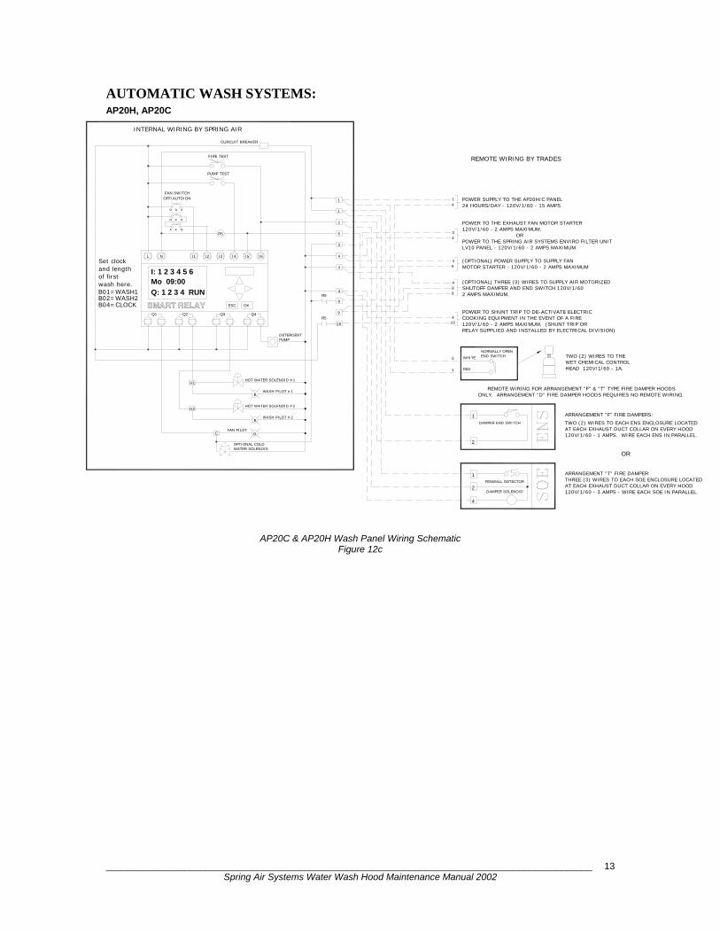
AUTOMATIC WASH SYSTEMS: AP20H, AP20C
AP20C & AP20H Wash Panel Wiring Schematic Figure 12c
I1
Q: 1 2 3 4 RUN
SMART RELAY
INTERNAL WIRING BY SPRING AIR
H2
H1
Set clockand length
wash here.
B02=WASH2B01=WASH1
B04=CLOCK
of firstMo 09:00
Q1 Q2
I: 1 2 3 4 5 6
L N
OFF/AUTO/ONFAN SWITCH
REMOTE WIRING BY TRADES
120V/1/60 - 2 AMPS MAXIMUM.
24 HOURS/DAY - 120V/1/60 - 15 AMPSPOWER SUPPLY TO THE AP20H/C PANEL
2 AMPS MAXIMUM.
RELAY SUPPLIED AND INSTALLED BY ELECTRICAL DIVISION)120V/1/60 - 2 AMPS MAXIMUM. (SHUNT TRIP ORCOOKING EQUIPMENT IN THE EVENT OF A FIREPOWER TO SHUNT TRIP TO DE-ACTIVATE ELECTRIC
SHUTOFF DAMPER AND END SWITCH 120V/1/60 (OPTIONAL) THREE (3) WIRES TO SUPPLY AIR MOTORIZED
MOTOR STARTER - 120V/1/60 - 2 AMPS MAXIMUM(OPTIONAL) POWER SUPPLY TO SUPPLY FAN
LV10 PANEL - 120V/1/60 - 2 AMPS MAXIMUM.POWER TO THE SPRING AIR SYSTEMS ENVIRO FILTER UNIT
POWER TO THE EXHAUST FAN MOTOR STARTER
DAMPER END SWITCH
REMOTE WIRING FOR ARRANGEMENT "F" & "T" TYPE FIRE DAMPER HOODSONLY. ARRANGEMENT "D" FIRE DAMPER HOODS REQUIRES NO REMOTE WIRING.
FAN PILOTC
WATER SOLENOID
G
OPTIONAL COLD
WASH PILOT #1
HOT WATER SOLENOID #1
HOT WATER SOLENOID #2
WASH PILOT #2
B
B
DETERGENTPUMP
2
4
2
1
1
WHITE
RED
5
1
R5
ESC
Q3 Q4
OK
I2 I3 I6I4 I5
R5
R5
CURCUIT BREAKER
FIRE TEST
PUMP TEST
35
4
8
9
10
4
3
4
489
410
4
49
1
1
2
41
OR
ARRANGEMENT "T" FIRE DAMPER:
ARRANGEMENT "F" FIRE DAMPERS:
TWO (2) WIRES TO THEWET CHEMICAL CONTROLHEAD 120V/1/60 - 1A.
120V/1/60 - 3 AMPS - WIRE EACH SOE IN PARALLEL.
THREE (3) WIRES TO EACH SOE ENCLOSURE LOCATED
120V/1/60 - 1 AMPS. WIRE EACH ENS IN PARALLEL.
AT EACH EXHAUST DUCT COLLAR ON EVERY HOOD
AT EACH EXHAUST DUCT COLLAR ON EVERY HOODTWO (2) WIRES TO EACH ENS ENCLOSURE LOCATED
FENWALL DETECTOR
DAMPER SOLENOID
END SWITCHNORMALLY OPEN
ORx x o
xo x
oo x
_____________________________________________________________________________________________ Spring Air Systems Water Wash Hood Maintenance Manual 2002
14
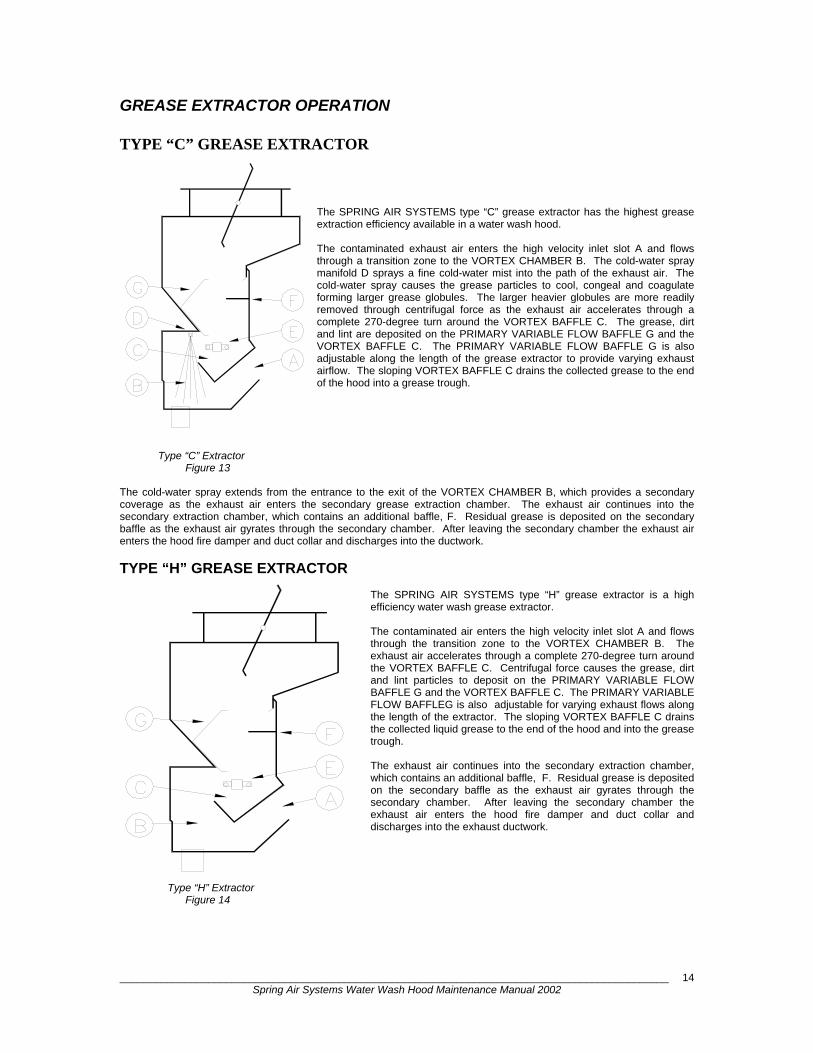
GREASE EXTRACTOR OPERATION
TYPE “C” GREASE EXTRACTOR The SPRING AIR SYSTEMS type “C” grease extractor has the highest grease extraction efficiency available in a water wash hood. The contaminated exhaust air enters the high velocity inlet slot A and flows through a transition zone to the VORTEX CHAMBER B. The cold-water spray manifold D sprays a fine cold-water mist into the path of the exhaust air. The cold-water spray causes the grease particles to cool, congeal and coagulate forming larger grease globules. The larger heavier globules are more readily removed through centrifugal force as the exhaust air accelerates through a complete 270-degree turn around the VORTEX BAFFLE C. The grease, dirt and lint are deposited on the PRIMARY VARIABLE FLOW BAFFLE G and the VORTEX BAFFLE C. The PRIMARY VARIABLE FLOW BAFFLE G is also adjustable along the length of the grease extractor to provide varying exhaust airflow. The sloping VORTEX BAFFLE C drains the collected grease to the end of the hood into a grease trough.
Type “C” Extractor Figure 13 The cold-water spray extends from the entrance to the exit of the VORTEX CHAMBER B, which provides a secondary coverage as the exhaust air enters the secondary grease extraction chamber. The exhaust air continues into the secondary extraction chamber, which contains an additional baffle, F. Residual grease is deposited on the secondary baffle as the exhaust air gyrates through the secondary chamber. After leaving the secondary chamber the exhaust air enters the hood fire damper and duct collar and discharges into the ductwork.
TYPE “H” GREASE EXTRACTOR The SPRING AIR SYSTEMS type “H” grease extractor is a high efficiency water wash grease extractor. The contaminated air enters the high velocity inlet slot A and flows through the transition zone to the VORTEX CHAMBER B. The exhaust air accelerates through a complete 270-degree turn around the VORTEX BAFFLE C. Centrifugal force causes the grease, dirt and lint particles to deposit on the PRIMARY VARIABLE FLOW BAFFLE G and the VORTEX BAFFLE C. The PRIMARY VARIABLE FLOW BAFFLEG is also adjustable for varying exhaust flows along the length of the extractor. The sloping VORTEX BAFFLE C drains the collected liquid grease to the end of the hood and into the grease trough. The exhaust air continues into the secondary extraction chamber, which contains an additional baffle, F. Residual grease is deposited on the secondary baffle as the exhaust air gyrates through the secondary chamber. After leaving the secondary chamber the exhaust air enters the hood fire damper and duct collar and discharges into the exhaust ductwork.
Type “H” Extractor Figure 14
_____________________________________________________________________________________________ Spring Air Systems Water Wash Hood Maintenance Manual 2002
15
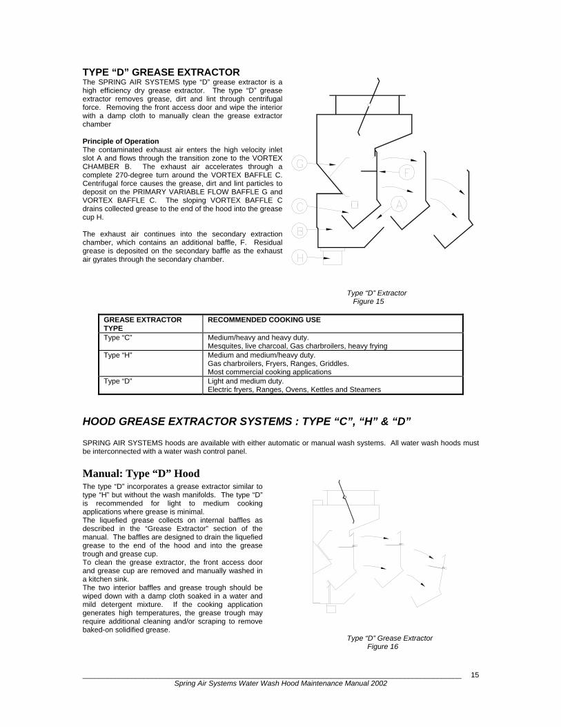
TYPE “D” GREASE EXTRACTOR The SPRING AIR SYSTEMS type “D” grease extractor is a high efficiency dry grease extractor. The type “D” grease extractor removes grease, dirt and lint through centrifugal force. Removing the front access door and wipe the interior with a damp cloth to manually clean the grease extractor chamber Principle of Operation The contaminated exhaust air enters the high velocity inlet slot A and flows through the transition zone to the VORTEX CHAMBER B. The exhaust air accelerates through a complete 270-degree turn around the VORTEX BAFFLE C. Centrifugal force causes the grease, dirt and lint particles to deposit on the PRIMARY VARIABLE FLOW BAFFLE G and VORTEX BAFFLE C. The sloping VORTEX BAFFLE C drains collected grease to the end of the hood into the grease cup H. The exhaust air continues into the secondary extraction chamber, which contains an additional baffle, F. Residual grease is deposited on the secondary baffle as the exhaust air gyrates through the secondary chamber. Type “D” Extractor Figure 15
GREASE EXTRACTOR TYPE
RECOMMENDED COOKING USE
Type “C” Medium/heavy and heavy duty. Mesquites, live charcoal, Gas charbroilers, heavy frying
Type “H” Medium and medium/heavy duty. Gas charbroilers, Fryers, Ranges, Griddles. Most commercial cooking applications
Type “D”
Light and medium duty. Electric fryers, Ranges, Ovens, Kettles and Steamers
HOOD GREASE EXTRACTOR SYSTEMS : TYPE “C”, “H” & “D” SPRING AIR SYSTEMS hoods are available with either automatic or manual wash systems. All water wash hoods must be interconnected with a water wash control panel.
Manual: Type “D” Hood The type “D” incorporates a grease extractor similar to type “H” but without the wash manifolds. The type “D” is recommended for light to medium cooking applications where grease is minimal. The liquefied grease collects on internal baffles as described in the “Grease Extractor” section of the manual. The baffles are designed to drain the liquefied grease to the end of the hood and into the grease trough and grease cup. To clean the grease extractor, the front access door and grease cup are removed and manually washed in a kitchen sink. The two interior baffles and grease trough should be wiped down with a damp cloth soaked in a water and mild detergent mixture. If the cooking application generates high temperatures, the grease trough may require additional cleaning and/or scraping to remove baked-on solidified grease. Type “D” Grease Extractor Figure 16
_____________________________________________________________________________________________ Spring Air Systems Water Wash Hood Maintenance Manual 2002
16
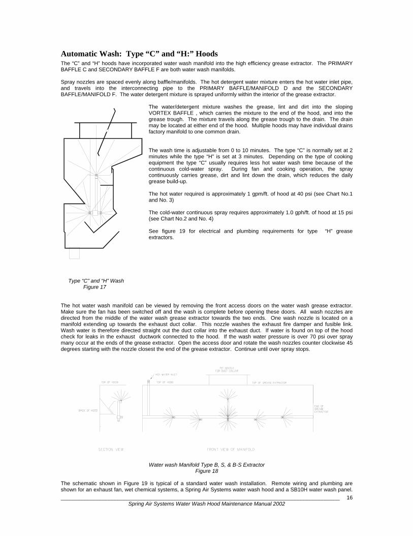
Automatic Wash: Type “C” and “H:” Hoods The “C” and “H” hoods have incorporated water wash manifold into the high efficiency grease extractor. The PRIMARY BAFFLE C and SECONDARY BAFFLE F are both water wash manifolds. Spray nozzles are spaced evenly along baffle/manifolds. The hot detergent water mixture enters the hot water inlet pipe, and travels into the interconnecting pipe to the PRIMARY BAFFLE/MANIFOLD D and the SECONDARY BAFFLE/MANIFOLD F. The water detergent mixture is sprayed uniformly within the interior of the grease extractor.
The water/detergent mixture washes the grease, lint and dirt into the sloping VORTEX BAFFLE , which carries the mixture to the end of the hood, and into the grease trough. The mixture travels along the grease trough to the drain. The drain may be located at either end of the hood. Multiple hoods may have individual drains factory manifold to one common drain. The wash time is adjustable from 0 to 10 minutes. The type “C” is normally set at 2 minutes while the type “H” is set at 3 minutes. Depending on the type of cooking equipment the type “C” usually requires less hot water wash time because of the continuous cold-water spray. During fan and cooking operation, the spray continuously carries grease, dirt and lint down the drain, which reduces the daily grease build-up. The hot water required is approximately 1 gpm/ft. of hood at 40 psi (see Chart No.1 and No. 3) The cold-water continuous spray requires approximately 1.0 gph/ft. of hood at 15 psi (see Chart No.2 and No. 4) See figure 19 for electrical and plumbing requirements for type “H” grease extractors.
Type “C” and “H” Wash Figure 17 The hot water wash manifold can be viewed by removing the front access doors on the water wash grease extractor. Make sure the fan has been switched off and the wash is complete before opening these doors. All wash nozzles are directed from the middle of the water wash grease extractor towards the two ends. One wash nozzle is located on a manifold extending up towards the exhaust duct collar. This nozzle washes the exhaust fire damper and fusible link. Wash water is therefore directed straight out the duct collar into the exhaust duct. If water is found on top of the hood check for leaks in the exhaust ductwork connected to the hood. If the wash water pressure is over 70 psi over spray many occur at the ends of the grease extractor. Open the access door and rotate the wash nozzles counter clockwise 45 degrees starting with the nozzle closest the end of the grease extractor. Continue until over spray stops.
Water wash Manifold Type B, S, & B-S Extractor Figure 18
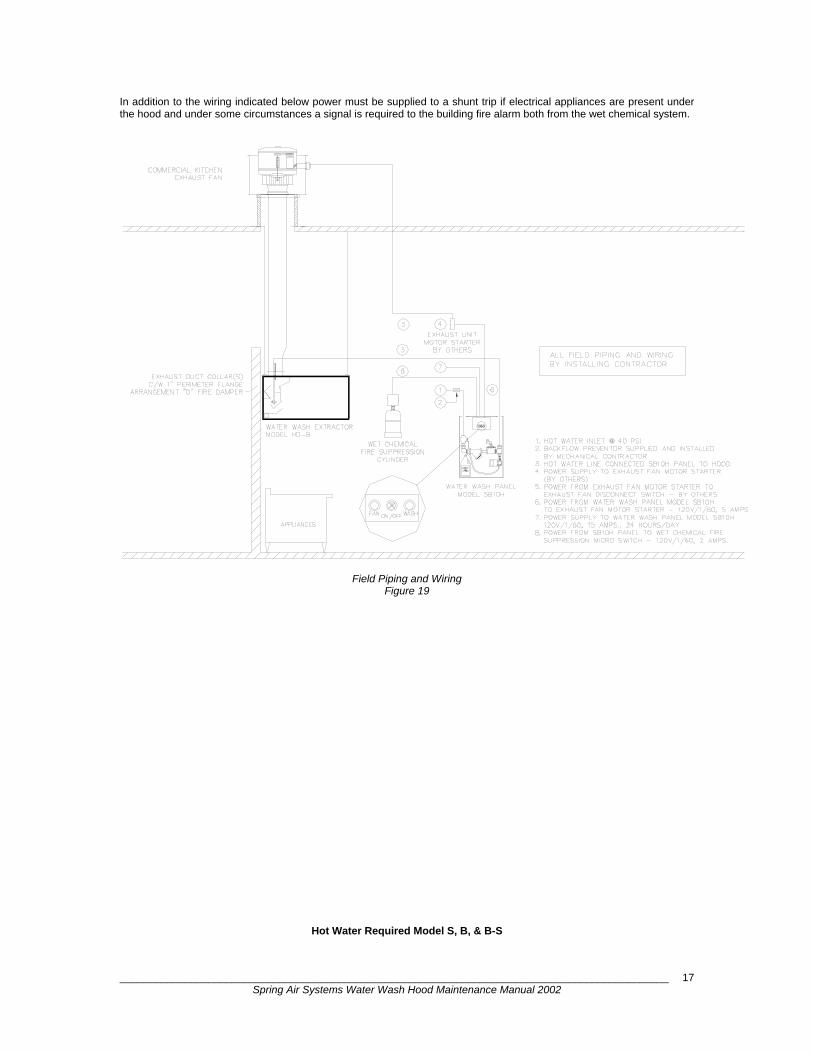
The schematic shown in Figure 19 is typical of a standard water wash installation. Remote wiring and plumbing are shown for an exhaust fan, wet chemical systems, a Spring Air Systems water wash hood and a SB10H water wash panel.
_____________________________________________________________________________________________ Spring Air Systems Water Wash Hood Maintenance Manual 2002
17
In addition to the wiring indicated below power must be supplied to a shunt trip if electrical appliances are present under the hood and under some circumstances a signal is required to the building fire alarm both from the wet chemical system.
Field Piping and Wiring Figure 19
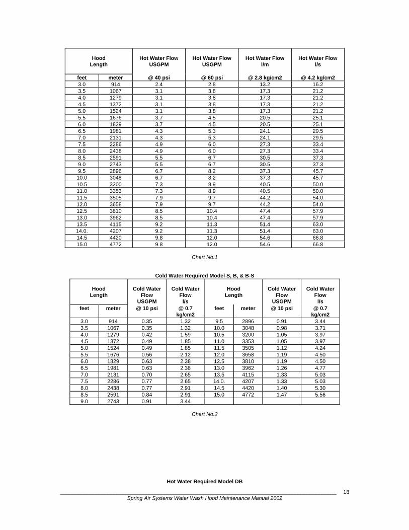
Hot Water Required Model S, B, & B-S
_____________________________________________________________________________________________ Spring Air Systems Water Wash Hood Maintenance Manual 2002
18
Hood
Length
Hot Water Flow
USGPM
Hot Water Flow
USGPM
Hot Water Flow
l/m
Hot Water Flow
l/s
feet meter @ 40 psi @ 60 psi @ 2.8 kg/cm2 @ 4.2 kg/cm2 3.0 914 2.4 2.8 13.2 16.2 3.5 1067 3.1 3.8 17.3 21.2 4.0 1279 3.1 3.8 17.3 21.2 4.5 1372 3.1 3.8 17.3 21.2 5.0 1524 3.1 3.8 17.3 21.2 5.5 1676 3.7 4.5 20.5 25.1 6.0 1829 3.7 4.5 20.5 25.1 6.5 1981 4.3 5.3 24.1 29.5 7.0 2131 4.3 5.3 24.1 29.5 7.5 2286 4.9 6.0 27.3 33.4 8.0 2438 4.9 6.0 27.3 33.4 8.5 2591 5.5 6.7 30.5 37.3 9.0 2743 5.5 6.7 30.5 37.3 9.5 2896 6.7 8.2 37.3 45.7
10.0 3048 6.7 8.2 37.3 45.7 10.5 3200 7.3 8.9 40.5 50.0 11.0 3353 7.3 8.9 40.5 50.0 11.5 3505 7.9 9.7 44.2 54.0 12.0 3658 7.9 9.7 44.2 54.0 12.5 3810 8.5 10.4 47.4 57.9 13.0 3962 8.5 10.4 47.4 57.9 13.5 4115 9.2 11.3 51.4 63.0 14.0. 4207 9.2 11.3 51.4 63.0 14.5 4420 9.8 12.0 54.6 66.8 15.0 4772 9.8 12.0 54.6 66.8
Chart No.1
Cold Water Required Model S, B, & B-S
Hood Length
Cold Water
Flow USGPM
Cold Water
Flow l/s
Hood
Length
Cold Water
Flow USGPM
Cold Water
Flow l/s
feet meter @ 10 psi @ 0.7 kg/cm2
feet meter @ 10 psi @ 0.7 kg/cm2
3.0 914 0.35 1.32 9.5 2896 0.91 3.44 3.5 1067 0.35 1.32 10.0 3048 0.98 3.71 4.0 1279 0.42 1.59 10.5 3200 1.05 3.97 4.5 1372 0.49 1.85 11.0 3353 1.05 3.97 5.0 1524 0.49 1.85 11.5 3505 1.12 4.24 5.5 1676 0.56 2.12 12.0 3658 1.19 4.50 6.0 1829 0.63 2.38 12.5 3810 1.19 4.50 6.5 1981 0.63 2.38 13.0 3962 1.26 4.77 7.0 2131 0.70 2.65 13.5 4115 1.33 5.03 7.5 2286 0.77 2.65 14.0. 4207 1.33 5.03 8.0 2438 0.77 2.91 14.5 4420 1.40 5.30 8.5 2591 0.84 2.91 15.0 4772 1.47 5.56 9.0 2743 0.91 3.44
Chart No.2
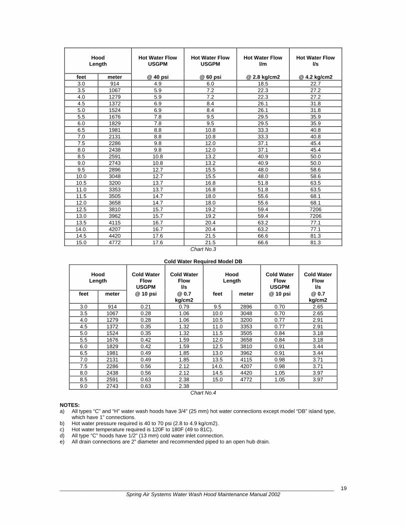
Hot Water Required Model DB
_____________________________________________________________________________________________ Spring Air Systems Water Wash Hood Maintenance Manual 2002
19
Hood
Length
Hot Water Flow
USGPM
Hot Water Flow
USGPM
Hot Water Flow
l/m
Hot Water Flow
l/s
feet meter @ 40 psi @ 60 psi @ 2.8 kg/cm2 @ 4.2 kg/cm2 3.0 914 4.9 6.0 18.5 22.7 3.5 1067 5.9 7.2 22.3 27.2 4.0 1279 5.9 7.2 22.3 27.2 4.5 1372 6.9 8.4 26.1 31.8 5.0 1524 6.9 8.4 26.1 31.8 5.5 1676 7.8 9.5 29.5 35.9 6.0 1829 7.8 9.5 29.5 35.9 6.5 1981 8.8 10.8 33.3 40.8 7.0 2131 8.8 10.8 33.3 40.8 7.5 2286 9.8 12.0 37.1 45.4 8.0 2438 9.8 12.0 37.1 45.4 8.5 2591 10.8 13.2 40.9 50.0 9.0 2743 10.8 13.2 40.9 50.0 9.5 2896 12.7 15.5 48.0 58.6
10.0 3048 12.7 15.5 48.0 58.6 10.5 3200 13.7 16.8 51.8 63.5 11.0 3353 13.7 16.8 51.8 63.5 11.5 3505 14.7 18.0 55.6 68.1 12.0 3658 14.7 18.0 55.6 68.1 12.5 3810 15.7 19.2 59.4 7206 13.0 3962 15.7 19.2 59.4 7206 13.5 4115 16.7 20.4 63.2 77.1 14.0. 4207 16.7 20.4 63.2 77.1 14.5 4420 17.6 21.5 66.6 81.3 15.0 4772 17.6 21.5 66.6 81.3
Chart No.3
Cold Water Required Model DB
Hood Length
Cold Water
Flow USGPM
Cold Water
Flow l/s
Hood
Length
Cold Water
Flow USGPM
Cold Water
Flow l/s
feet meter @ 10 psi @ 0.7 kg/cm2
feet meter @ 10 psi @ 0.7 kg/cm2
3.0 914 0.21 0.79 9.5 2896 0.70 2.65 3.5 1067 0.28 1.06 10.0 3048 0.70 2.65 4.0 1279 0.28 1.06 10.5 3200 0.77 2.91 4.5 1372 0.35 1.32 11.0 3353 0.77 2.91 5.0 1524 0.35 1.32 11.5 3505 0.84 3.18 5.5 1676 0.42 1.59 12.0 3658 0.84 3.18 6.0 1829 0.42 1.59 12.5 3810 0.91 3.44 6.5 1981 0.49 1.85 13.0 3962 0.91 3.44 7.0 2131 0.49 1.85 13.5 4115 0.98 3.71 7.5 2286 0.56 2.12 14.0. 4207 0.98 3.71 8.0 2438 0.56 2.12 14.5 4420 1.05 3.97 8.5 2591 0.63 2.38 15.0 4772 1.05 3.97 9.0 2743 0.63 2.38
Chart No.4 NOTES: a) All types “C” and “H” water wash hoods have 3/4” (25 mm) hot water connections except model “DB” island type,
which have 1” connections. b) Hot water pressure required is 40 to 70 psi (2.8 to 4.9 kg/cm2). c) Hot water temperature required is 120F to 180F (49 to 81C). d) All type “C” hoods have 1/2” (13 mm) cold water inlet connection. e) All drain connections are 2” diameter and recommended piped to an open hub drain.
_____________________________________________________________________________________________ Spring Air Systems Water Wash Hood Maintenance Manual 2002
20
Hood and Damper Assembly THE SURFACE FIRE SUPPRESSION SYSTEM is always installed in am commercial kitchen. They are required by national and local code. The surface fire suppression system is a wet chemical or a water sprinkler system. In the event of a fire on the cooking surface electric thermostat or fusible links activates the systems. These systems must be UL/ULC listed. NOTE: The exhaust fan should remain on after a surface fire suppression system has activated. A properly designed hood and damper assembly is UL/ULC listed to impede the spread of fire from the kitchen hood into the exhaust duct. The UL/ULC listed hood and damper assembly is an important part of the kitchen ventilation system. SPRING AIR SYSTEMS has three (3) arrangements of hood and damper assemblies available, arrangement “T”, “F”, and “D”, thermostatic or fusible link activated systems respectively.
All SB & SBA Panels - Arrangement “D” Hoods The wet chemical surface fire suppression system is connected to the water wash panel. Terminals 5 & 1 are connected to the normally open micro switch located in the control head of the wet chemical cylinder. When the wet chemical fire suppression system activates the micro switch closes sending 120V/1/60 power back to the control panel. Fire relay R6 is activated, the hot water solenoid valve is energized releasing water into the interior of the grease extractor, and power to the motorized fresh air damper and supply fan motor starter is shut off.
NOTE: The exhaust fan remains on after a primary surface fire suppression system has activated.
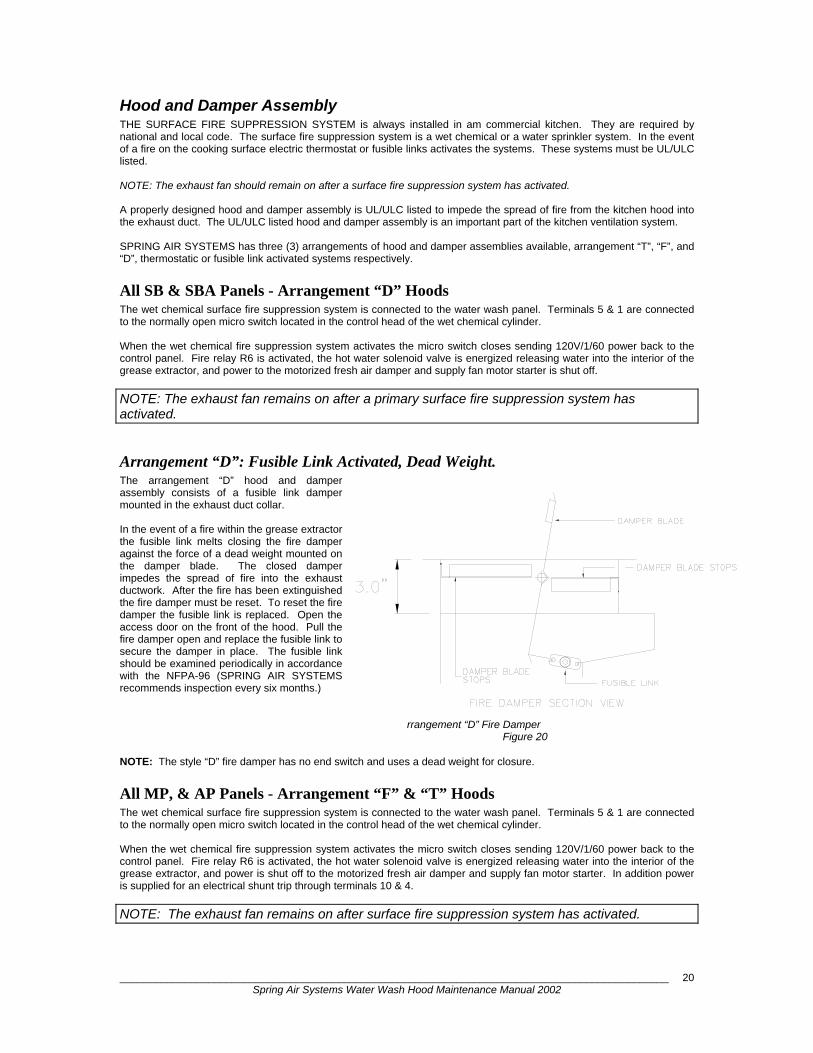
Arrangement “D”: Fusible Link Activated, Dead Weight. The arrangement “D” hood and damper assembly consists of a fusible link damper mounted in the exhaust duct collar. In the event of a fire within the grease extractor the fusible link melts closing the fire damper against the force of a dead weight mounted on the damper blade. The closed damper impedes the spread of fire into the exhaust ductwork. After the fire has been extinguished the fire damper must be reset. To reset the fire damper the fusible link is replaced. Open the access door on the front of the hood. Pull the fire damper open and replace the fusible link to secure the damper in place. The fusible link should be examined periodically in accordance with the NFPA-96 (SPRING AIR SYSTEMS recommends inspection every six months.)
Arrangement “D” Fire Damper
Figure 20 NOTE: The style “D” fire damper has no end switch and uses a dead weight for closure.
All MP, & AP Panels - Arrangement “F” & “T” Hoods The wet chemical surface fire suppression system is connected to the water wash panel. Terminals 5 & 1 are connected to the normally open micro switch located in the control head of the wet chemical cylinder. When the wet chemical fire suppression system activates the micro switch closes sending 120V/1/60 power back to the control panel. Fire relay R6 is activated, the hot water solenoid valve is energized releasing water into the interior of the grease extractor, and power is shut off to the motorized fresh air damper and supply fan motor starter. In addition power is supplied for an electrical shunt trip through terminals 10 & 4.
NOTE: The exhaust fan remains on after surface fire suppression system has activated.
_____________________________________________________________________________________________ Spring Air Systems Water Wash Hood Maintenance Manual 2002
21
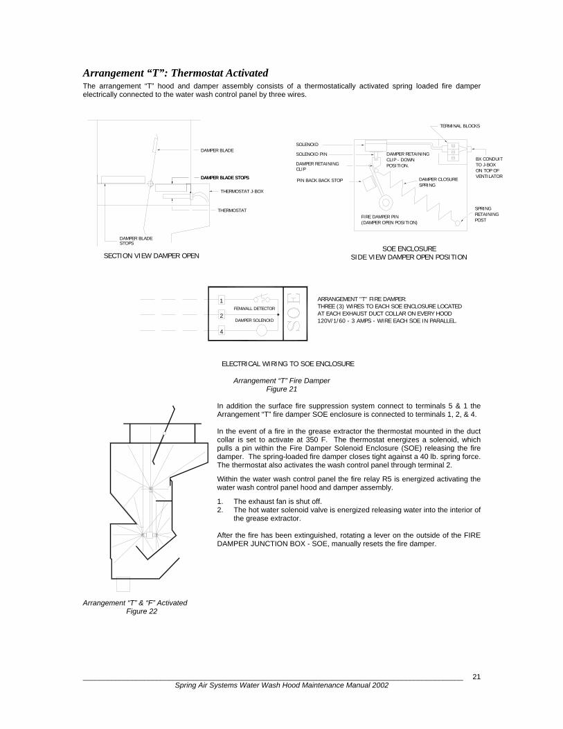
Arrangement “T”: Thermostat Activated The arrangement “T” hood and damper assembly consists of a thermostatically activated spring loaded fire damper electrically connected to the water wash control panel by three wires.
Arrangement “T” Fire Damper Figure 21
In addition the surface fire suppression system connect to terminals 5 & 1 the Arrangement “T” fire damper SOE enclosure is connected to terminals 1, 2, & 4. In the event of a fire in the grease extractor the thermostat mounted in the duct collar is set to activate at 350 F. The thermostat energizes a solenoid, which pulls a pin within the Fire Damper Solenoid Enclosure (SOE) releasing the fire damper. The spring-loaded fire damper closes tight against a 40 lb. spring force. The thermostat also activates the wash control panel through terminal 2.
Within the water wash control panel the fire relay R5 is energized activating the water wash control panel hood and damper assembly.
1. The exhaust fan is shut off. 2. The hot water solenoid valve is energized releasing water into the interior of
the grease extractor. After the fire has been extinguished, rotating a lever on the outside of the FIRE DAMPER JUNCTION BOX - SOE, manually resets the fire damper.
Arrangement “T” & “F” Activated Figure 22
ELECTRICAL WIRING TO SOE ENCLOSURE
SECTION VIEW DAMPER OPEN
DAMPER SOLENOID
4
FENWALL DETECTOR1
2
DAMPER BLADESTOPS
DAMPER BLADE STOPSDAMPER BLADE STOPS
THERMOSTAT
THERMOSTAT J-BOX
DAMPER BLADE
120V/1/60 - 3 AMPS - WIRE EACH SOE IN PARALLEL.
THREE (3) WIRES TO EACH SOE ENCLOSURE LOCATEDAT EACH EXHAUST DUCT COLLAR ON EVERY HOOD
SIDE VIEW DAMPER OPEN POSITIONSOE ENCLOSURE
ARRANGEMENT "T" FIRE DAMPER:
DAMPER RETAINING
(DAMPER OPEN POSITION)
POSITION.
PIN BACK BACK STOP
CLIP
FIRE DAMPER PIN
SOLENOID
SOLENOID PIN
DAMPER RETAININGCLIP - DOWN
ON TOP OFVENTILATOR
SPRINGRETAININGPOST
DAMPER CLOSURESPRING
BX CONDUITTO J-BOX
TERMINAL BLOCKS
_____________________________________________________________________________________________ Spring Air Systems Water Wash Hood Maintenance Manual 2002
22
The arrangement “T” has three advantages: 1. The damper is spring loaded to provide a positive closure and seal when closed. 2. The thermostat set at 350F (177C) responds quickly to activate the spring in the event of a fire. 3. The fire damper can be periodically tested by putting a jumper across terminals 1 & 2 in the water wash panel or
heating the thermostat to 350F (177C). The damper will simulate a fire condition and then must be manually reset. After the fire has been completely extinguished the fire damper must be reset. To reset the fire damper rotate the stainless steel handle located on the side of the Fire Damper Solenoid Enclosure 90 degrees clockwise. When access is restricted on model B and DB hoods an optional factory installed access door can be located in the roof of the hood in the vicinity of the duct collar.
The fire damper can be tested periodically (SPRING AIR SYSTEMS recommends testing the fire damper every six months). Putting a jumper across terminals 1 & 2 located in the water wash control panel tests the damper.
NOTES:
1. AT THE FIRST SIGN OF A KITCHEN FIRE NOTIFY THE FIRE DEPARTMENT IMMEDIATELY.
2. THE HOOD AND DAMPER ASSEMBLY IS NOT A SUBSTITUTE FOR THE SURFACE FIRE SUPPRESSION SYSTEM. (WET CHEMICAL, SPRINKLER, ETC.) A SURFACE FIRE PROTECTION MUST BE INSTALLED IN ACCORDANCE WITH APPLICABLE CODES.
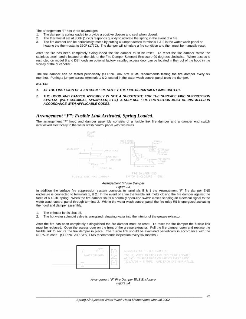
Arrangement “F”: Fusible Link Activated, Spring Loaded. The arrangement “F” hood and damper assembly consists of a fusible link fire damper and a damper end switch interlocked electrically to the water wash control panel with two wires.
Arrangement “F” Fire Damper Figure 23
In addition the surface fire suppression system connects to terminals 5 & 1 the Arrangement “F” fire damper ENS enclosure is connected to terminals 1, & 2. In the event of a fire the fusible link melts closing the fire damper against the force of a 40-lb. spring. When the fire damper shuts a normally open-end switch closes sending an electrical signal to the water wash control panel through terminal 2. Within the water wash control panel the fire relay R5 is energized activating the hood and damper assembly. 1. The exhaust fan is shut off. 2. The hot water solenoid valve is energized releasing water into the interior of the grease extractor. After the fire has been completely extinguished the fire damper must be reset. To reset the fire damper the fusible link must be replaced. Open the access door on the front of the grease extractor. Pull the fire damper open and replace the fusible link to secure the fire damper in place. The fusible link should be examined periodically in accordance with the NFPA-96 code. (SPRING AIR SYSTEMS recommends inspection every six months.)
Arrangement “F” Fire Damper ENS Enclosure
Figure 24
_____________________________________________________________________________________________ Spring Air Systems Water Wash Hood Maintenance Manual 2002
23
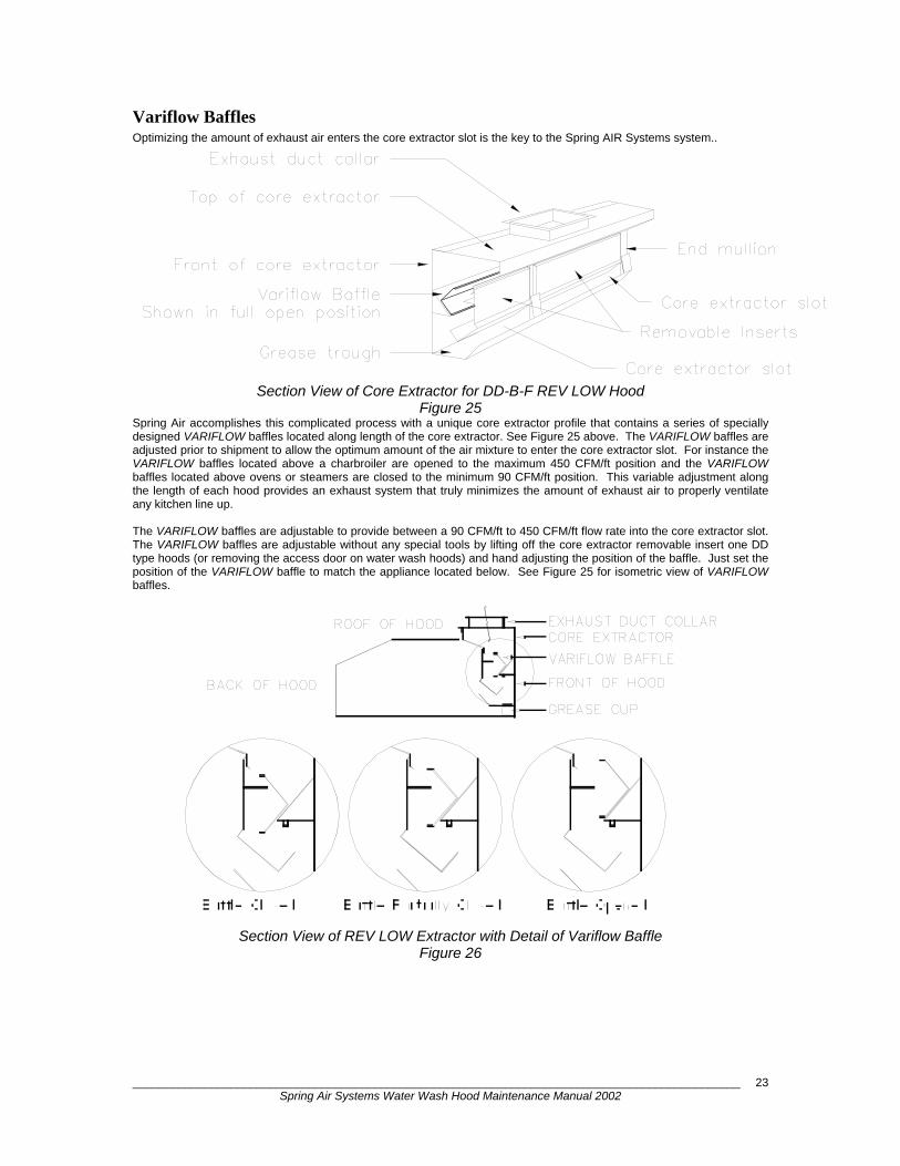
Variflow Baffles Optimizing the amount of exhaust air enters the core extractor slot is the key to the Spring AIR Systems system..
Section View of Core Extractor for DD-B-F REV LOW Hood
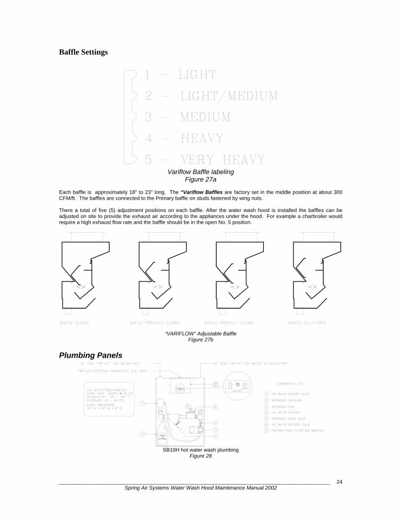
Figure 25 Spring Air accomplishes this complicated process with a unique core extractor profile that contains a series of specially designed VARIFLOW baffles located along length of the core extractor. See Figure 25 above. The VARIFLOW baffles are adjusted prior to shipment to allow the optimum amount of the air mixture to enter the core extractor slot. For instance the VARIFLOW baffles located above a charbroiler are opened to the maximum 450 CFM/ft position and the VARIFLOW baffles located above ovens or steamers are closed to the minimum 90 CFM/ft position. This variable adjustment along the length of each hood provides an exhaust system that truly minimizes the amount of exhaust air to properly ventilate any kitchen line up. The VARIFLOW baffles are adjustable to provide between a 90 CFM/ft to 450 CFM/ft flow rate into the core extractor slot. The VARIFLOW baffles are adjustable without any special tools by lifting off the core extractor removable insert one DD type hoods (or removing the access door on water wash hoods) and hand adjusting the position of the baffle. Just set the position of the VARIFLOW baffle to match the appliance located below. See Figure 25 for isometric view of VARIFLOW baffles.
Section View of REV LOW Extractor with Detail of Variflow Baffle
Figure 26
_____________________________________________________________________________________________ Spring Air Systems Water Wash Hood Maintenance Manual 2002
24
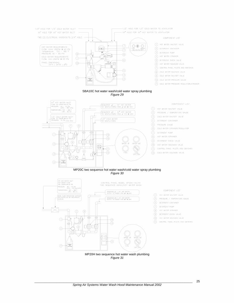
Baffle Settings
Variflow Baffle labeling
Figure 27a
Each baffle is approximately 18” to 23” long. The “Variflow Baffles are factory set in the middle position at about 300 CFM/ft. The baffles are connected to the Primary baffle on studs fastened by wing nuts. There a total of five (5) adjustment positions on each baffle. After the water wash hood is installed the baffles can be adjusted on site to provide the exhaust air according to the appliances under the hood. For example a charbroiler would require a high exhaust flow rate and the baffle should be in the open No. 5 position.
“VARIFLOW” Adjustable Baffle Figure 27b
Plumbing Panels
SB10H hot water wash plumbing
Figure 28
_____________________________________________________________________________________________ Spring Air Systems Water Wash Hood Maintenance Manual 2002
25
SBA10C hot water wash/cold water spray plumbing Figure 29
MP20C two sequence hot water wash/cold water spray plumbing
Figure 30
MP20H two sequence hot water wash plumbing
Figure 31

_____________________________________________________________________________________________ Spring Air Systems Water Wash Hood Maintenance Manual 2002
26
AP30C three sequence hot water wash plumbing
Figure 32
MP30H three sequence hot water wash plumbing Figure 33

_____________________________________________________________________________________________ Spring Air Systems Water Wash Hood Maintenance Manual 2002
27
SBA10C & SBA10H single sequence electrical wiring Figure 34
AP10C & AP10H single sequence electrical wiring Figure 35
NOTE 1:ALL REMOTE ELECTRIAL WIRING
AND NATIONAL CODE REQUIREMENTSSHALL CONFORM TO ALL LOCAL
INTERNAL WIRING BY SPRING AIR
Q: 1 2 3 4 RUN
Mo 09:00I: 1 2 3 4 5 6
SMART RELAYQ1
L
Q2
N I1 I2
FAN SWITCHOFF/AUTO/ON
PUMPDETERGENT
HOT WATER SOLENOID
WASH PILOTH B
FAN PILOT
OPTIONAL COLDWATER SOLENOID
C G
ESC
Q3
OK
Q4
I3 I4 I5 I6
CURCUIT BREAKER
4
4
8
9
3
5
1
END SWITCH TWO (2) WIRES TO THE
MOTOR STARTERS OVERLOADS
5
1
RED
WHITEWET CHEMICAL CONTROLHEAD 120V/1/60 - 1A.
ELECTRICAL DIVISIONAND DISCONNECTS BY
NOTE 2:
SHUTOFF DAMPER AND END SWITCH 120V/1/60 (OPTIONAL) THREE (3) WIRES TO SUPPLY AIR MOTORIZED
MOTOR STARTER - 120V/1/60 - 2 AMPS MAXIMUM(OPTIONAL) POWER SUPPLY TO SUPPLY FAN
LV10 PANEL - 120V/1/60 - 2 AMPS MAXIMUM.POWER TO THE SPRING AIR SYSTEMS ENVIRO FILTER UNIT
POWER TO THE EXHAUST FAN MOTOR STARTER
24 HOURS/DAY - 120V/1/60 - 15 AMPSPOWER SUPPLY TO THE SB10H/C PANEL
NORMALLY OPEN
2 AMPS MAXIMUM.948
94
REMOTE WIRING BY TRADES
120V/1/60 - 2 AMPS MAXIMUM.34
41
ORx x o
xo x
oo x
H
C
HOT WATER SOLENOID
DETERGENT
WASH PILOTB
PUMP
WATER SOLENOIDOPTIONAL COLD
FAN PILOTG
1
5
INTERNAL WIRING BY SPRING AIR
FIRE TEST
PUMP TEST
I3
FAN SWITCH
Q: 1 2 3 4 RUN
Mo 09:00I: 1 2 3 4 5 6
SMART RELAYQ1 Q2
NL I1 I2
OFF/AUTO/ON
10
ESC OK
Q3 Q4
I4 I5 I6
9
8
4
4
104
984
9
3
4
5
2
1
1
4
43
41
CURCUIT BREAKER
120V/1/60 - 3 AMPS - WIRE EACH SOE IN PARALLEL.
THREE (3) WIRES TO EACH SOE ENCLOSURE LOCATED
120V/1/60 - 1 AMPS. WIRE EACH ENS IN PARALLEL.
ONLY. ARRANGEMENT "D" FIRE DAMPER HOODS REQUIRES NO REMOTE WIRING.
AT EACH EXHAUST DUCT COLLAR ON EVERY HOOD
AT EACH EXHAUST DUCT COLLAR ON EVERY HOODTWO (2) WIRES TO EACH ENS ENCLOSURE LOCATED
4
REMOTE WIRING FOR ARRANGEMENT "F" & "T" TYPE FIRE DAMPER HOODS
ARRANGEMENT "T" FIRE DAMPER:
ARRANGEMENT "F" FIRE DAMPERS:
TWO (2) WIRES TO THEWET CHEMICAL CONTROLHEAD 120V/1/60 - 1A.
DAMPER END SWITCH
DAMPER SOLENOID
FENWALL DETECTOR
2
1
2
1
END SWITCHNORMALLY OPEN
RED
WHITE
OR
RELAY SUPPLIED AND INSTALLED BY ELECTRICAL DIVISION)120V/1/60 - 2 AMPS MAXIMUM. (SHUNT TRIP ORCOOKING EQUIPMENT IN THE EVENT OF A FIREPOWER TO SHUNT TRIP TO DE-ACTIVATE ELECTRIC
SHUTOFF DAMPER AND END SWITCH 120V/1/60 (OPTIONAL) THREE (3) WIRES TO SUPPLY AIR MOTORIZED
MOTOR STARTER - 120V/1/60 - 2 AMPS MAXIMUM(OPTIONAL) POWER SUPPLY TO SUPPLY FAN
LV10 PANEL - 120V/1/60 - 2 AMPS MAXIMUM.POWER TO THE SPRING AIR SYSTEMS ENVIRO FILTER UNIT
POWER TO THE EXHAUST FAN MOTOR STARTER
24 HOURS/DAY - 120V/1/60 - 15 AMPSPOWER SUPPLY TO THE AP10H/C PANEL
2 AMPS MAXIMUM.
120V/1/60 - 2 AMPS MAXIMUM.OR
REMOTE WIRING BY TRADES
x x o
xo x
oo x

_____________________________________________________________________________________________ Spring Air Systems Water Wash Hood Maintenance Manual 2002
28
AP20C & AP20H two sequence electrical wiring Figure 36
AP30C & AP30H three sequence electrical wiring
Figure 37
I1
Q: 1 2 3 4 RUN
SMART RELAY
INTERNAL WIRING BY SPRING AIR
H2
H1
Set clockand length
wash here.
B02=WASH2B01=WASH1
B04=CLOCK
of firstMo 09:00
Q1 Q2
I: 1 2 3 4 5 6
L N
OFF/AUTO/ONFAN SWITCH
REMOTE WIRING BY TRADES
120V/1/60 - 2 AMPS MAXIMUM.
24 HOURS/DAY - 120V/1/60 - 15 AMPSPOWER SUPPLY TO THE AP20H/C PANEL
2 AMPS MAXIMUM.
RELAY SUPPLIED AND INSTALLED BY ELECTRICAL DIVISION)120V/1/60 - 2 AMPS MAXIMUM. (SHUNT TRIP ORCOOKING EQUIPMENT IN THE EVENT OF A FIREPOWER TO SHUNT TRIP TO DE-ACTIVATE ELECTRIC
SHUTOFF DAMPER AND END SWITCH 120V/1/60 (OPTIONAL) THREE (3) WIRES TO SUPPLY AIR MOTORIZED
MOTOR STARTER - 120V/1/60 - 2 AMPS MAXIMUM(OPTIONAL) POWER SUPPLY TO SUPPLY FAN
LV10 PANEL - 120V/1/60 - 2 AMPS MAXIMUM.POWER TO THE SPRING AIR SYSTEMS ENVIRO FILTER UNIT
POWER TO THE EXHAUST FAN MOTOR STARTER
DAMPER END SWITCH
REMOTE WIRING FOR ARRANGEMENT "F" & "T" TYPE FIRE DAMPER HOODSONLY. ARRANGEMENT "D" FIRE DAMPER HOODS REQUIRES NO REMOTE WIRING.
FAN PILOTC
WATER SOLENOID
G
OPTIONAL COLD
WASH PILOT #1
HOT WATER SOLENOID #1
HOT WATER SOLENOID #2
WASH PILOT #2
B
B
DETERGENTPUMP
2
4
2
1
1
WHITE
RED
5
1
R5
ESC
Q3 Q4
OK
I2 I3 I6I4 I5
R5
R5
CURCUIT BREAKER
FIRE TEST
PUMP TEST
35
4
8
9
10
4
3
4
489
410
4
49
1
1
2
41
OR
ARRANGEMENT "T" FIRE DAMPER:
ARRANGEMENT "F" FIRE DAMPERS:
TWO (2) WIRES TO THEWET CHEMICAL CONTROLHEAD 120V/1/60 - 1A.
120V/1/60 - 3 AMPS - WIRE EACH SOE IN PARALLEL.
THREE (3) WIRES TO EACH SOE ENCLOSURE LOCATED
120V/1/60 - 1 AMPS. WIRE EACH ENS IN PARALLEL.
AT EACH EXHAUST DUCT COLLAR ON EVERY HOOD
AT EACH EXHAUST DUCT COLLAR ON EVERY HOODTWO (2) WIRES TO EACH ENS ENCLOSURE LOCATED
FENWALL DETECTOR
DAMPER SOLENOID
END SWITCHNORMALLY OPEN
ORx x o
xo x
oo x
H2
H3
WASH PILOT #3
WASH PILOT #2
HOT WATER SOLENOID #3
HOT WATER SOLENOID #2
B
B
I1
Q: 1 2 3 4 RUN
SMART RELAY
INTERNAL WIRING BY SPRING AIR
I1
SMART RELAY
Q: 1 2 3 4 RUN
H1
Set length
wash here.and thirdof second
B03=WASH3B02=WASH2
Q1 Q2
I: 1 2 3 4 5 6
L N
C
NSet clock L
B01=WASH1B04=CLOCK
wash here.
and lengthof first
Q1 Q2
Mo 09:00I: 1 2 3 4 5 6
FAN SWITCHOFF/AUTO/ON
ALL HOT WATER SOLENOID VALVESARE LOCATED REMOTE FROM PANEL
POWER SUPPLY TO THE AP20H/C PANEL24 HOURS/DAY - 120V/1/60 - 15 AMPS
REMOTE WIRING BY TRADES
POWER TO THE EXHAUST FAN MOTOR STARTER120V/1/60 - 2 AMPS MAXIMUM.
LV10 PANEL - 120V/1/60 - 2 AMPS MAXIMUM.
(OPTIONAL) POWER SUPPLY TO SUPPLY FANMOTOR STARTER - 120V/1/60 - 2 AMPS MAXIMUM
SHUTOFF DAMPER AND END SWITCH 120V/1/60 2 AMPS MAXIMUM.
POWER TO SHUNT TRIP TO DE-ACTIVATE ELECTRICCOOKING EQUIPMENT IN THE EVENT OF A FIRE120V/1/60 - 2 AMPS MAXIMUM. (SHUNT TRIP OR
POWER TO THE SPRING AIR SYSTEMS ENVIRO FILTER UNIT
(OPTIONAL) THREE (3) WIRES TO SUPPLY AIR MOTORIZED
RELAY SUPPLIED AND INSTALLED BY ELECTRICAL DIVISION)
DAMPER END SWITCH
REMOTE WIRING FOR ARRANGEMENT "F" & "T" TYPE FIRE DAMPER HOODSONLY. ARRANGEMENT "D" FIRE DAMPER HOODS REQUIRES NO REMOTE WIRING.
ESC OK
Q3 Q4
I3I2 I6I4 I5
HOT WATER SOLENOID #1
WASH PILOT #1
WATER SOLENOIDOPTIONAL COLD
FAN PILOT
B
G
4
1
2
1
2
5 WHITE
RED1
I6I4I3I2 I5
ESC OK
Q3 Q4
DETERGENTPUMP
R5
FIRE TEST
PUMP TEST
8
10
9R5
4
4
R54
410
94
84
9
1
1
2
3
5
4
43
1
NORMALLY OPEN
WET CHEMICAL CONTROLTWO (2) WIRES TO THE
OR
ARRANGEMENT "F" FIRE DAMPERS:TWO (2) WIRES TO EACH ENS ENCLOSURE LOCATEDAT EACH EXHAUST DUCT COLLAR ON EVERY HOOD
ARRANGEMENT "T" FIRE DAMPER:
AT EACH EXHAUST DUCT COLLAR ON EVERY HOOD
120V/1/60 - 1 AMPS. WIRE EACH ENS IN PARALLEL.
THREE (3) WIRES TO EACH SOE ENCLOSURE LOCATED
120V/1/60 - 3 AMPS - WIRE EACH SOE IN PARALLEL.
HEAD 120V/1/60 - 1A.
FENWALL DETECTOR
DAMPER SOLENOID
END SWITCH
OR
CURCUIT BREAKER
x x o
xo x
oo x
_____________________________________________________________________________________________ Spring Air Systems Water Wash Hood Maintenance Manual 2002
29
MAINTENANCE SCHEDULE
DAILY: 1. After the manual or automatic wash wipe down the interior and exterior surfaces of the hood canopy and the
underside of the grease trough. Use a damp cloth and avoid abrasive cleansers.
WEEKLY: 1. Check the level of detergent in the control panel. (Panels with low detergent alarm will automatically signal when a
refill is necessary). 2. During the normal fan operation visually inspect the cold-water spray nozzles. The nozzles can be observed by
looking directly into the hood inlet slot. If a nozzle is not spraying remove/clean and or replace. (Type “C” extractors only.)
3. After the daily wash inspect the hot water wash manifold and nozzles. Open the front access door to view the wash manifold. If grease or dirt is still visible remove/clean and or replace the hot water nozzle. Prior to replacement check that hot water pressure and temperature are within design ranges.
MONTHLY: 1. Check operation of detergent pump. Inspect for leaks and broken fittings. 2. After the daily wash inspect the complete interior of the grease extractor. Open the front access door and check the
VORTEX BAFFLE and grease trough for any debris. Check that the drain is free and clear.
SIX MONTHS: 1. Clean all line strainers located in the control panel (hot water and cold water). 2. Check exhaust fan belts for alignment, tightness, and wear. Adjust and/or replace. 3. Measure the exhaust volume. Design exhaust volume is stamped on the ULC plate. Refer to the Exhaust Air
Measurement section of this manual for detailed instructions. 4. Check the Second Line Fire Protection System.
Arrangement “T”: Manually activate system by placing a jumper across terminals 1 & 2 in the control panel. The following sequence should occur:
(i) Fire damper closes. (ii) Exhaust fan shuts off. (iii) Hot water solenoid is energized spraying water into the interior of the grease extractor. Reset the fire damper by
rotating the reset handle 90 degrees clockwise. (The handle is located on the side of the fire solenoid enclosure ENS.)
Arrangement “F”: Visually inspect the fusible link, which holds the fire damper open. Clean and/or replace. Manually activate the Second Line Fire Protection System placing a jumper across terminals 1 & 2 in the control panel. The following sequence should occur:
(i) Exhaust fan shuts off. (ii) Hot water solenoid is engaged spraying water into the interior of the grease extractor.
CAUTION: PRIOR TO ACTIVATING THE HOOD AND DAMPER ASSEMBLY CHECK IF THE PRIMARY FIRE PROTECTION SYSTEM OR BUILDING FIRE ALARM IS ELECTRICALLY CONNECTED TO THE WATER WASH CONTROL PANEL.
_____________________________________________________________________________________________ Spring Air Systems Water Wash Hood Maintenance Manual 2002
30
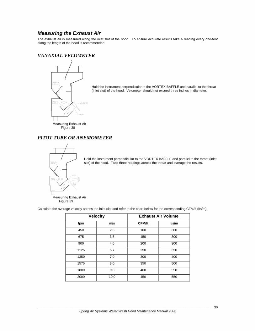
Measuring the Exhaust Air The exhaust air is measured along the inlet slot of the hood. To ensure accurate results take a reading every one-foot along the length of the hood is recommended.
VANAXIAL VELOMETER
Hold the instrument perpendicular to the VORTEX BAFFLE and parallel to the throat (inlet slot) of the hood. Velometer should not exceed three inches in diameter.
Measuring Exhaust Air Figure 38
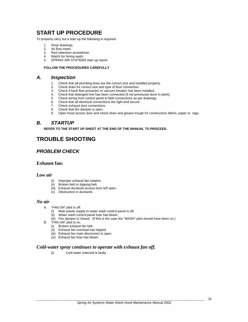
PITOT TUBE OR ANEMOMETER Hold the instrument perpendicular to the VORTEX BAFFLE and parallel to the throat (inlet slot) of the hood. Take three readings across the throat and average the results.
Measuring Exhaust Air Figure 39 Calculate the average velocity across the inlet slot and refer to the chart below for the corresponding CFM/ft (l/s/m).
Velocity Exhaust Air Volume
fpm m/s CFM/ft l/s/m
450 2.3 100 300
675 3.5 150 300
900 4.6 200 300
1125 5.7 250 350
1350 7.0 300 400
1575 8.0 350 500
1800 9.0 400 550
2000 10.0 450 550
_____________________________________________________________________________________________ Spring Air Systems Water Wash Hood Maintenance Manual 2002
31
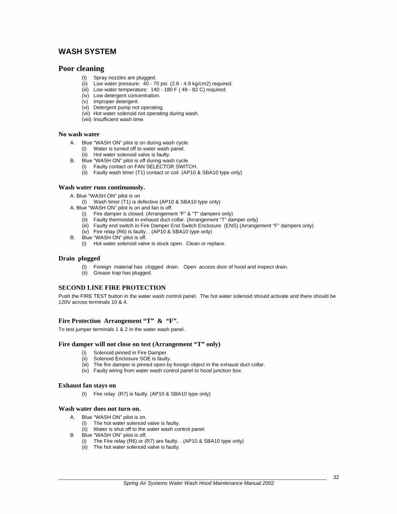
START UP PROCEDURE To properly carry out a start up the following is required.
1. Shop drawings. 2. Air flow meter. 3. Red robertson screwdriver. 4. Watch for timing wash. 5. SPRING AIR SYSTEMS start up report. FOLLOW THE PROCEDURES CAREFULLY
A. Inspection 1. Check that all plumbing lines are the correct size and installed properly. 2. Check drain for correct size and type of floor connection. 3. Check if back flow preventor or vacuum breaker has been installed. 4. Check that detergent line has been connected (if not previously done in plant). 5. Check wiring from control panel to field connections as per drawings. 6. Check that all electrical connections are tight and secure. 7. Check exhaust duct connections. 8. Check that fire damper is open. 9. Open hood access door and check drain and grease trough for construction debris, paper or rags.
B. STARTUP REFER TO THE START UP SHEET AT THE END OF THE MANUAL TO PROCEED.
TROUBLE SHOOTING
PROBLEM CHECK
Exhaust fan:
Low air (I) Improper exhaust fan rotation. (ii) Broken belt or slipping belt. (iii) Exhaust ductwork access door left open. (v) Obstruction in ductwork.
No air A. “FAN ON” pilot is off.
(i) Main power supply to water wash control panel is off. (ii) Water wash control panel fuse has blown. (iii) Fire damper is closed. (If this is the case the “WASH” pilot should have been on.)
B. “FAN ON” pilot is on. (i) Broken exhaust fan belt. (ii) Exhaust fan overload has tripped. (iii) Exhaust fan main disconnect is open. (iv) Exhaust fan fuse has blown.
Cold-water spray continues to operate with exhaust fan off. (i) Cold water solenoid is faulty
_____________________________________________________________________________________________ Spring Air Systems Water Wash Hood Maintenance Manual 2002
32
WASH SYSTEM
Poor cleaning (I) Spray nozzles are plugged. (ii) Low water pressure: 40 - 70 psi (2.8 - 4.9 kg/cm2) required. (iii) Low water temperature: 140 - 180 F ( 49 - 82 C) required. (iv) Low detergent concentration. (v) Improper detergent. (vi) Detergent pump not operating. (vii) Hot water solenoid not operating during wash. (viii) Insufficient wash time.
No wash water A. Blue “WASH ON” pilot is on during wash cycle.
(i) Water is turned off to water wash panel. (ii) Hot water solenoid valve is faulty.
B. Blue “WASH ON” pilot is off during wash cycle. (i) Faulty contact on FAN SELECTOR SWITCH. (ii) Faulty wash timer (T1) contact or coil. (AP10 & SBA10 type only)
Wash water runs continuously. A. Blue “WASH ON” pilot is on
(I) Wash timer (T1) is defective (AP10 & SBA10 type only) A. Blue “WASH ON” pilot is on and fan is off.
(i) Fire damper is closed. (Arrangement “F” & “T” dampers only) (ii) Faulty thermostat in exhaust duct collar. (Arrangement “T” damper only) (iii) Faulty end switch in Fire Damper End Switch Enclosure (ENS) (Arrangement “F” dampers only) (iv) Fire relay (R6) is faulty. . (AP10 & SBA10 type only)
B. Blue “WASH ON” pilot is off. (i) Hot water solenoid valve is stuck open. Clean or replace.
Drain plugged (I) Foreign material has clogged drain. Open access door of hood and inspect drain. (ii) Grease trap has plugged.
SECOND LINE FIRE PROTECTION Push the FIRE TEST button in the water wash control panel. The hot water solenoid should activate and there should be 120V across terminals 10 & 4.
Fire Protection Arrangement “T” & “F”. To test jumper terminals 1 & 2 in the water wash panel.
Fire damper will not close on test (Arrangement “T” only) (i) Solenoid pinned in Fire Damper (ii) Solenoid Enclosure SOE is faulty. (iii) The fire damper is pinned open by foreign object in the exhaust duct collar. (iv) Faulty wiring from water wash control panel to hood junction box.
Exhaust fan stays on (I) Fire relay (R7) is faulty. (AP10 & SBA10 type only)
Wash water does not turn on. A. Blue “WASH ON” pilot is on.
(I) The hot water solenoid valve is faulty. (ii) Water is shut off to the water wash control panel.
B Blue “WASH ON” pilot is off. (i) The Fire relay (R6) or (R7) are faulty. . (AP10 & SBA10 type only) (ii) The hot water solenoid valve is faulty.

_____________________________________________________________________________________________ Spring Air Systems Water Wash Hood Maintenance Manual 2002
33
Water Wash Hood Start-up Report General Information Job Name Date Customer Location Spring Air Service Exhaust Fan Model No. Manufacturer Upblast Discharge yes no Exhaust Fan HP Exhaust Air Design (CFM) Supply Air Design (CFM) Hood mounting Height from finished floor to front of hood
Make Up Air Systems Good Fair Poor None Hood Item
Model Length Width No. of Baffles Baffle Size * Design CFM
Baffle No. Left to Right
Baffle Setting Velocity Reading (fpm)
Calculated Exhaust Volume per Baffle (CFM) **
1 2 3 4 5 6
Total Exhaust Measured CFM Design Exhaust CFM Hood Item
Model Length Width No. of Baffles Baffle Size * Design CFM
Baffle No. Left to Right
Baffle Setting Velocity Reading (fpm)
Calculated Exhaust Volume per Baffle (CFM) **
1 2 3 4 5 6
Total Exhaust Measured CFM Design Exhaust CFM
_____________________________________________________________________________________________ Spring Air Systems Water Wash Hood Maintenance Manual 2002
34
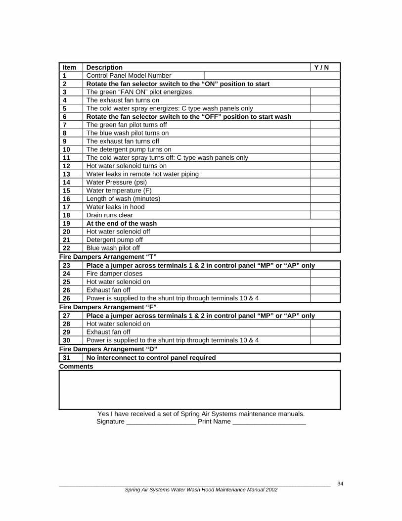
Item Description Y / N 1 Control Panel Model Number 2 Rotate the fan selector switch to the “ON” position to start3 The green “FAN ON” pilot energizes 4 The exhaust fan turns on 5 The cold water spray energizes: C type wash panels only 6 Rotate the fan selector switch to the “OFF” position to start wash 7 The green fan pilot turns off 8 The blue wash pilot turns on 9 The exhaust fan turns off 10 The detergent pump turns on 11 The cold water spray turns off: C type wash panels only 12 Hot water solenoid turns on 13 Water leaks in remote hot water piping 14 Water Pressure (psi) 15 Water temperature (F) 16 Length of wash (minutes) 17 Water leaks in hood 18 Drain runs clear 19 At the end of the wash 20 Hot water solenoid off 21 Detergent pump off 22 Blue wash pilot off
Fire Dampers Arrangement “T” 23 Place a jumper across terminals 1 & 2 in control panel “MP” or “AP” only 24 Fire damper closes 25 Hot water solenoid on 26 Exhaust fan off 26 Power is supplied to the shunt trip through terminals 10 & 4
Fire Dampers Arrangement “F” 27 Place a jumper across terminals 1 & 2 in control panel “MP” or “AP” only 28 Hot water solenoid on 29 Exhaust fan off 30 Power is supplied to the shunt trip through terminals 10 & 4
Fire Dampers Arrangement “D” 31 No interconnect to control panel required
Comments
Yes I have received a set of Spring Air Systems maintenance manuals. Signature ___________________ Print Name ____________________
_____________________________________________________________________________________________ Spring Air Systems Water Wash Hood Maintenance Manual 2002
35
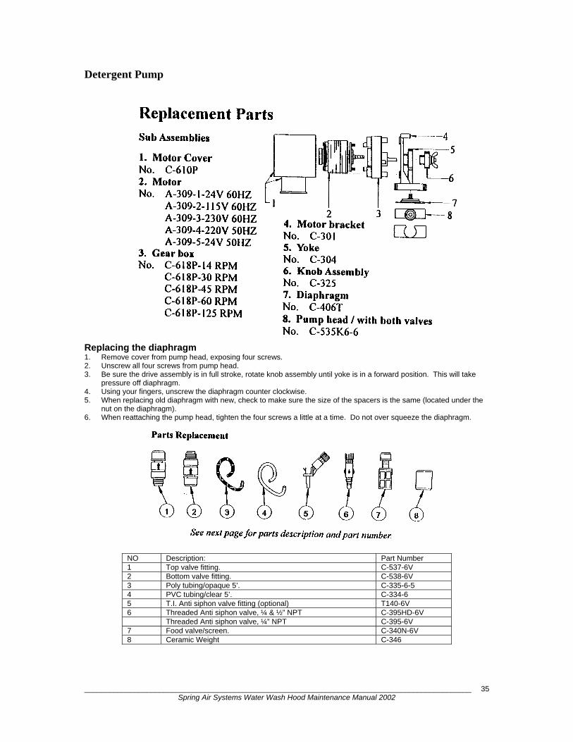
Detergent Pump
Replacing the diaphragm 1. Remove cover from pump head, exposing four screws. 2. Unscrew all four screws from pump head. 3. Be sure the drive assembly is in full stroke, rotate knob assembly until yoke is in a forward position. This will take
pressure off diaphragm. 4. Using your fingers, unscrew the diaphragm counter clockwise. 5. When replacing old diaphragm with new, check to make sure the size of the spacers is the same (located under the
nut on the diaphragm). 6. When reattaching the pump head, tighten the four screws a little at a time. Do not over squeeze the diaphragm.
NO Description: Part Number 1 Top valve fitting. C-537-6V 2 Bottom valve fitting. C-538-6V 3 Poly tubing/opaque 5’. C-335-6-5 4 PVC tubing/clear 5’. C-334-6 5 T.I. Anti siphon valve fitting (optional) T140-6V 6 Threaded Anti siphon valve, ¼ & ½” NPT C-395HD-6V Threaded Anti siphon valve, ¼” NPT C-395-6V 7 Food valve/screen. C-340N-6V 8 Ceramic Weight C-346
_____________________________________________________________________________________________ Spring Air Systems Water Wash Hood Maintenance Manual 2002
36
Q: 1 2 3 4
Mo 09:14 to program a second (Weekend Operation) or third weekly setting go the the section"Setting Weekend Operation"Q: 1 2 3 4
Setting Weekly Fan "ON" and "OFF" times
9. Press to move to the hour that the fan will stop in the evening. Press
to change the hour you want the fan to stop each evening. Press to move
to the minute the the fan will start in the morning. Press to change the minutes.
to change the hour you want the fan to start in each morning. Press to move
8. Press to move to the hour that the fan will start in the morning. Press
fan will not automatically operate on Saturday or Sunday.not required to operate on that given day. The screen on the left indicates the
the fan will not start automatically any given day.6. Press to remove Monday from the weekly schedule. The - dash indicates
at 23:00 hours or 11:00 p.m. When the fan shuts off the wash activates.4. The clock has been factory set to turn the fan on at 6:00 a.m. and off
5. To change the above settings press
7. Press to move to the next day of the week. Press each time the fan is
1. Press these two buttons together
ESC
12. You have completed programming one weekly fan "On" and "Off" cycling. If you wish
11. If your selection is complete press and to return the the operating screen.
to the minute the fan stop in the evening. Press to change the minutes.
B04: No1D = - TWTF- -
B04: No1
I: 1 2 3 4 5 6
D = MTWTF- -On = 06: 30Off = 22: 30
B04: No1D = MTWTF- -On = 06: 30Off = 22: 30
Off = 2 3: 00On = 06: 30
10.Press
OK
B04: No1
On = 0 6: 00
B04: No1D = - TWTF- -
Off = 23: 00
B04: No1
On = 06: 00Off = 23: 00
D = - TWTF- -
Off = 23: 00On = 06: 00D = MTWTF-S
B04: No1D = MTWTFSSOn = 06: 00Off = 23: 00
Off = 23: 00On = 06: 00D = MTWTFSSB04: No1
>Set Param Set Clock 3. Press
OK
>Set Clock Set Param
Mo 09:00I: 1 2 3 4 5 6
Q: 1 2 3 4
2. Press
ESC ESC
The cursor will move to M = Monday.OK
OK
6. You have finished setting the clock.
move to year. Adjust the year by pressing
Adjust the day by pressing
5. To change the date press again. The month will be highlighted. Press
Adjust the minutes by pressing
4. To change the time press once. The hour will be highlighted. Press
3. To change the day of week press
1. Press these two buttons together
ESC
MM. DD. YY11. 13. 01
I: 1 2 3 4 5 6Su 11: 25
Set Clock
11. 11. 01MM. DD. YY
MM. DD. YY11. 13. 01
Set Clock
Su 11:25
Su 11:25
7. Press ESC
or
Set Clock
11. 13. 01MM. DD. YYMo 09:00Set Clock
Set Param>Set Clock
Mo 09:00
Su 09:00
Q: 1 2 3 4
or
OK
2. Press
I: 1 2 3 4 5 6
to return to the operating screen.
until correct year appears.
Press to move to day.
until correct day appear. Press to
until correct minutes appears.
Press to move to minutes.
until the correct day appears.
or
or
until the correct month appears.
and OK
or
until the correct hour appears.
OK
or
OKQ: 1 2 3 4
Mo 09:00I: 1 2 3 4 5 6
2. Press
OK
3. Press
Set Param>Set Clock
>Set Param Set Clock
1. Press these two buttons together
ESC
OK
The wash time has been factory pre-set at 2 minutes.
ESC
5. Press
D = MTWTFSS
Off = 23: 00On = 06: 00
B04: No1
Ta = 02:00m
T = 02:00mB01: T
T = 02:00mB01: T
T = 02:30mB01: T
Ta = 02:00m
OK
Ta = 02:00m
B01: T
Ta = 02:00m
I: 1 2 3 4 5 6
T = 02:30m
ESC
Q: 1 2 3 4
Mo 09:12
4. The clock has been factory set to turn the fan on at 6:00 a.m. and offat 23:00 hours or 11:00 p.m. When the fan shuts off the wash activates.To change these times see section "Programming the SMARTRELAY time clock.
7. Press to change the length the wash in minutes. Press to move to the
9. Press and to return to the operating screen.
the length of wash in seconds. Press to change the seconds.
6. To change the wash time press
8. Press if the wash time is correct.
Setting the Length of Wash
to change the hour you want the fan to start in each morning. Press to move
to the minute the the fan will start in the morning. Press to change the minute
Setting Weekend Operation
8. Press to move to the hour that the fan will start in the morning. Press
to the minute the fan stop in the evening. Press to change the minutes.
to change the hour you want the fan to stop each evening. Press to move
9. Press to move to the hour that the fan will stop in the evening. Press B04: No2
Off = - - : - -On = 10: 00D = - - - - - SS
B04: No2
On = - - : - -D = - - - - - SS
Off = - - : - -
ESC
1. Press these two buttons together
5. To set Weekend Operation press
6. Press to program the weekend operation.
7. Press five times to move to Saturday. Press to turn fan on Saturday.
4. The clock has been set to turn the fan on at 6:30 a.m. and off at 22:30 hoursor 10:30 p.m. When the fan shuts off the wash activates.
Press once to move to Sunday. Press to turn fan on Sunday.
On = 06: 30
B04: No2
B04: No2
Off = - - : - -
D = - - - - - SSOn = - - : - -
D = - - - - - - -On = - - : - -Off = - - : - -
OK
D = MTWTFSS
Off = 23: 00On = 06: 00
B04: No1
Off = 22: 30
B04: No1D = MTWTF- -
Set Clock>Set Param
OK
3. Press
Q: 1 2 3 4
>Set Clock Set Param
Mo 09:14I: 1 2 3 4 5 6
2. Press
OK
operating screen.
OK10. PressD = - - - - - SSOn = 10: 00Off = 23: 30
B04: No2If your selection is complete press and to return theESC ESC
11. You have completed programming weekend fan "On" and "Off" cycling.
Q: 1 2 3 4
Mo 10:24I: 1 2 3 4 5 6
Setting the Clock Time and DayI6I5I4I2I1 I3NL
I: 1 2 3 4 5 6
SMART RELAYQ1 Q2
Mo 09:00
Q: 1 2 3 4
Q3 Q4
ESC OK
Other Fine Products From SPRING AIR SYSTEMS...
Water Wash Ventilators Hot Water Wash Cold Water Spray/Hot Water Wash Water Wash Control Panels
Dry Extractor Hoods
RevLow Hoods
Dynaflow Hoods
Cartridge Hoods
Filter Hoods
Surface Fire Suppression
Commercial Kitchen Exhaust Fans
Kitchen Enviro Systems
KES - 100% Exhaust KRS - 80% Recirculation in Canada
Commercial Kitchen Supply Units
Compensating Hoods
Exhaust Fans
Zoneflow Kitchen Exhaust Balancing Dampers
Supply Fans
Commercial Kitchen Control Panels
Truflow Demand Ventilation Controls
Capture-i
Captur-r
Utility Distributions Systems
Phone: 866-874-4505, FAX: 905-338-1079, e-mail [email protected]
www.springairsystems.com