Embed Size (px)
Citation preview
Wynn Marine Ltd.
2-4 Merse Road, North Moons Moat, Redditch, Worcestershire B98 9HL
Tel: +44 (0) 1527 61243, Fax: +44 (0) 1527 66836
Email: [email protected] Website: http://www.wynn.co.uk
Installation & Maintenance Manual
Series 5010 Wash System
General Description of the Window Wash System The window wash system is supplied with water from the ship’s fresh water system. It is held in a storage tank that is topped up automatically. A high pressure boost pump draws water from this storage tank and delivers it through piping to groups of external nozzles above or below the bridge windows to remove salt deposits, grease and general debris in conjunction with the ship’s window wipers. When the wash is finished the wash water system piping is purged of water automatically by compressed air and the wipers then park. To cope with poor weather or operating conditions customers have the option to have detergent and/or anti-freeze additives injected into the wash water as well as the wash water heated if required. An option to have remote bridge control of these three functions is also available. The wash operation is controlled from the ship’s bridge by a key incorporated in the remote window wiper control keypad. Where wipers are not fitted the wash system is controlled by a dedicated keypad on the bridge. The optional facilities are operated by a local control panel mounted on the wash system sledge that will be sited within the ship’s bridge structure. While the shipbuilder will install the entire window wash system, the wash system components will be supplied in two separate groups - one group by the shipbuilder and one group by Wynn Marine Ltd. The latter group of components is mostly fitted to the wash module sledge and comprises the wash pump, liquid storage tanks, any of the optional facilities for heating or injecting anti-freeze/detergent additives, associated valves, piping, cabling and the overall control module and power supply terminal boxes.
Technical Specification Of Wash System
Wash Pump The pump is a peripheral turbine type with a cast iron body, stainless steel shaft and bronze impeller. A mechanical seal of carbon/ceramic/NBR is fitted. The bearings are pre-packed shielded ball bearings. The pump is designed to operate up to 80º C. The pump has an output of approximately 10Litres/min at 5bar and a maximum working pressure of 7.5bar. The pump complies with ISO 2548 Class C Annex B.
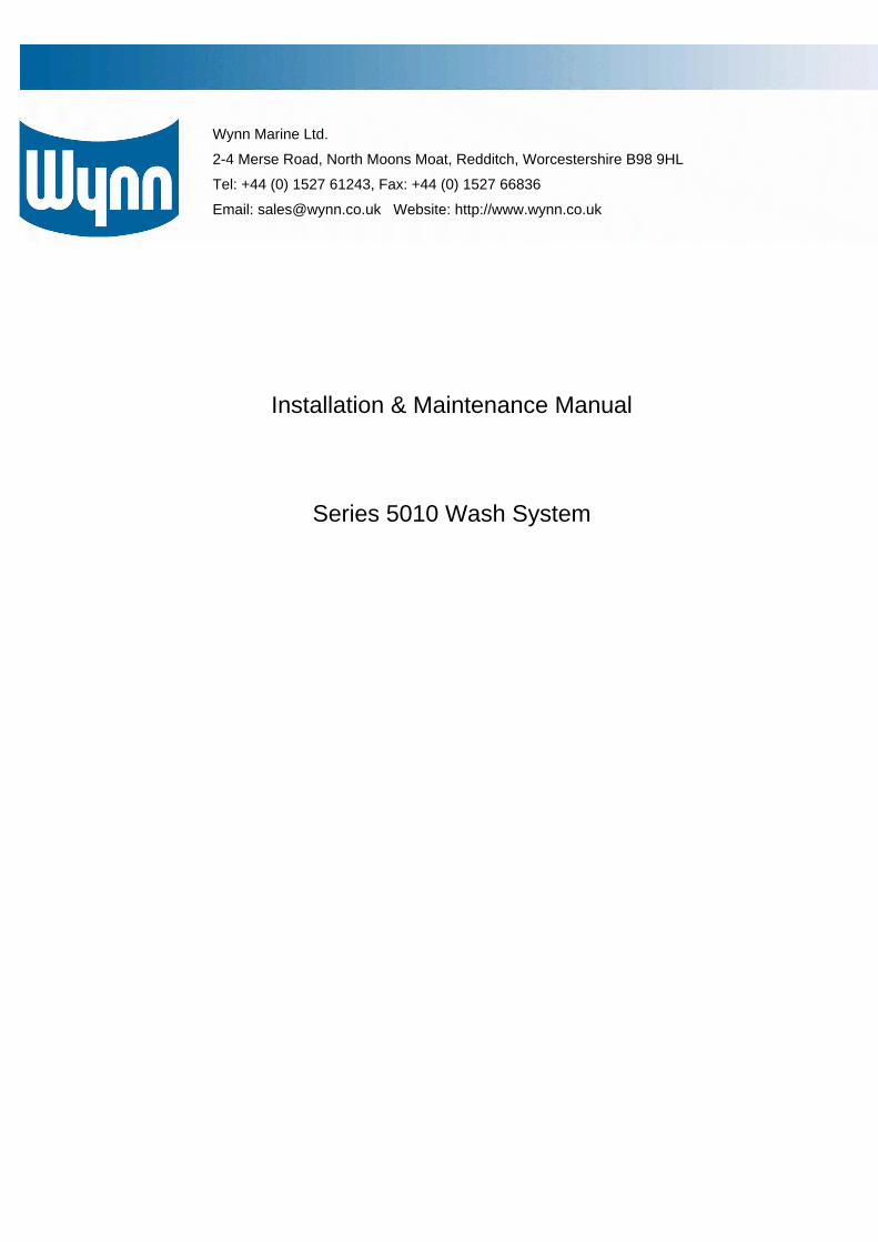
Wash Pump Motor The motor runs at a constant speed of 2850 rpm and is of the totally enclosed fan cooled 2-pole design for 115V or 230V ac ±10% single-phase 50Hz or 60Hz operation. The motor casing is of aluminium and the shaft of stainless steel. Insulation is to Class F and the protection to IP44 with automatic thermal overload. The motor is further protected by an overload circuit breaker.
Motor Specifications
Model Hz Voltage Fullload Current
HP KW Weight (Kg)
080M 50 230 AC 5.2A 0.8 0.59 9.2
Solenoid Valves for wash water control, air purge and ships’ water supply The valves are a 2/2 normally closed type with 1/4in BSP inlet and outlet ports, an 8mm diameter orifice, a brass body, VITON seats, stainless steel internals and operate between 0.1 to16bar and up to 90º C. The valves use a 115/230V ac ± 10% single phase 50/60Hz electrical supply and consume 8W. The solenoids are replaceable without tools.
Solenoid Valves for Anti-freeze and Detergent injection control (if these options are fitted) The valves are a 2/2 normally closed type with 1/4in BSP inlet and outlet ports, a 4mm diameter orifice, a brass body, FKM seat and stainless steel internals. Operating range is 0 to 15bar and up to 130º C. They use a 115/230V ac ± 10% single phase 50/60Hz electrical supply using 6VA.
Immersion heater fitted to wash water storage tank (if option is fitted) Capacity 3kW or 6kW Voltage 115/230V single phase ±10% 50Hz/60Hz Immersed length 280mm (3kW) or 406mm (6kW ) Element NiCr resistance wire sheathed in Incoloy 800 Thermostat Adjustable range 5º to 80º C with auto reset Enclosure Nylon-coated lightweight mild steel Mounting 2in square 4-bolt brass flange Cable entry 1 x M25 Test pressure 12bar IP Rating IP66
Liquid Storage Tanks for wash water, anti-freeze and detergent additives Capacity Wash water tank – 60 litres Anti-freeze additive tank – 22 litres (if this option is fitted) Detergent additive tank – 10 litres (if this option is fitted) Material Polyethylene Temperature limits -20º to 70º C Colour Natural High and low level Vertical operation, dual switching, 115/230V ac/120V dc, Float switches (wash water tank) 25VA max power, 0.6A max switching current Temperature gauge (wash water tank) Dial type with a 4in probe in stainless steel with 0º to 120º C range Low level switch (all 3 tanks) Internally mounted, reed type, polypropylene float switch Nozzles The nozzles produce a flat spray with tapered edges. They are of stainless steel or brass and have a 1/8in or 1/4in. BSPT male thread. The nozzle spray angle will be selected according to the dimensions of the ship’s windows and the location of the nozzle (i.e. above or below the window). The flow capacity will be approximately 2Litres/min per nozzle at 5bar.
The shipbuilder will supply the following: 1. Wash system water piping (with insulation as required) 2. Nozzle swan-necks 3. Wash system pressure gauge sited on the bridge 4. Wash system water temperature gauge sited on the bridge 5. Wash system water relief valve piped to ship’s drain 6. Fresh water supply to storage tank with a stopcock and in-line water filter 7. Ship’s drain for draining storage tanks and pump 8. 115V or 230V ac single phase 50 or 60Hz fused electrical supply 9. 24V dc supply with fused breaker (Optional supply by WYNN MARINE) 10. Control cabling from bridge control keypad to control module sited on wash system module sledge 11. Control cabling from control module on system sledge to wash water, air purge, ship’s water supply and
additive control solenoid valves (if fitted) 12. Compressed air supply (max 7bar) to purge control valve with a stopcock 13. Compressed air piping from stopcock to purge valve 14. Air pressure gauge on ship’s air supply system upstream of stopcock
Wynn Marine will supply the following to the shipbuilder for installation: 1. Nozzles 2. Solenoid valves to control wash water supply to nozzle groups 3. Solenoid valve to control air purging 4. Non-return check valve for air purge line 5. Rocker switches and panel with LED’s for additive injection (if fitted) 6. Wash system module to supply up to 10 nozzles simultaneously consisting of:
Motor-driven wash pump with 2 isolating valves Pressure gauge in pump discharge line
7. Non-return valve in pump discharge line 8. Wash water storage tank 9. Low level switch fitted to wash water tank 10. Solenoid valve to control supply of fresh water from ship’s cold water system to the washwater storage tank 11. Float switch unit in wash water tank with dual switching facility to operate solenoid valve supplying water
from the ship’s cold water system 12. Immersion heater with an adjustable thermostat (if this option is fitted) 13. Temperature gauge fitted to wash water storage tank (if this option is fitted) 14. Anti-freeze additive storage tank (if this option is fitted) 15. Low level switch fitted to anti-freeze storage tank (if this option is fitted) 16. Anti-freeze supply solenoid valve (if this option is fitted) 17. Anti-freeze additive injection metering valve (if this option is fitted) 18. Detergent additive storage tank (if this optional is fitted) 19. Low level switch fitted to detergent storage tank (if this option is fitted) 20. Detergent additive solenoid injection control valve (if this option is fitted) 21. Detergent additive injection metering valve (if this option is fitted) 22. Drain valve for Storage Tanks and Boost Pump 23. All associated piping and cabling between sledge mounted equipment 24. Dedicated adjustable Control Module incorporating relays, contactors and PCB’s, etc with fused power
supply terminals 25. Module sledge with 4 resilient mounts
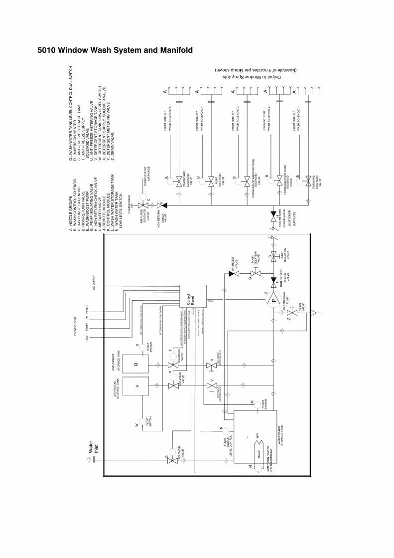
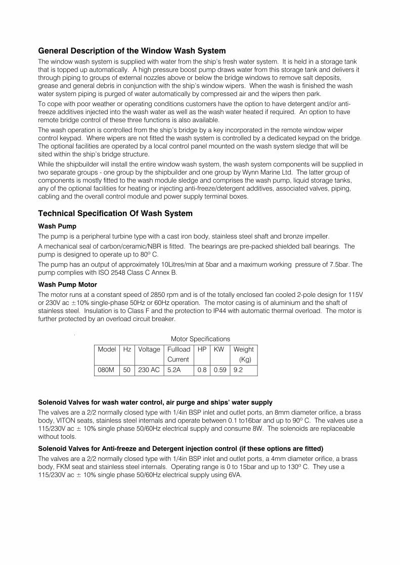
5010 Window Wash System and Manifold
Wat
erIn
let
P
B B B
Output to Window Spray Jets
M
Con
trol
Pan
el
O
U
R
AN
TI-F
RE
EZE
STO
RA
GE
TAN
K
Z
R
N
E
WAS
H W
ATER
STO
RA
GE
TAN
K
24V
CE
NTR
IFU
GAL
PU
MP
DE
TER
GEN
TS
TOR
AG
E TA
NK
A
DR
AIN
VALV
E
Hea
ter
IMM
ER
SIO
N H
EAT
ER
C/W
TH
ER
MO
STAT
T
HEA
TER
PUMP
A...
NO
ZZLE
GR
OU
PS
B...
WAS
H C
ON
TRO
L SO
LEN
OID
C...
AIR
PU
RG
E S
OLE
NO
IDD
..NO
N-R
ETU
RN
VAL
VEE
...W
AS
H B
OO
ST
PU
MP
G...
PU
MP
ISO
LATI
NG
VA
LVE
H...
NO
N-R
ETU
RN
CH
ECK
VAL
VEI..
.AIR
BLE
ED
VAL
VEJ.
..REM
OTE
MO
DU
LE
K...
CO
NTR
OL
MO
DU
LEL.
..WAS
H W
ATE
R S
TOR
AGE
TAN
KN
...W
ASH
WA
TER
TAN
K
LOW
LE
VEL
SWIT
CH
SW
ITC
HFL
OAT
X
Y
V
SW
ITC
HFL
OAT
LEV
EL C
ON
TRO
L
FLO
AT
SW
ITC
H
S
SW
ITC
HFL
OA
T
W
VA
LVE
SO
LEN
OID
S
OLE
NO
ID
VALV
E
MET
ERIN
G V
ALVE
AN
TI-F
REE
ZED
ETER
GE
NT
SO
LEN
OID
V
ALV
E
SHIP
S S
UP
PLY
SOLE
NO
ID V
ALV
E
WAT
ER T
AN
K LE
VEL
CO
NTR
OL
DET
ER
GE
NT
SUP
PLY
SOLE
NO
ID V
ALV
E
ANTI
-FR
EEZ
E S
UP
PLY
SOLE
NO
ID V
ALV
E
DET
ERG
EN
T LO
W L
EVEL
SW
ITC
H
AN
TI-F
REE
ZE L
OW
LE
VEL
SWIT
CH
WA
TER
LO
W L
EVEL
SW
ITC
H
MET
ERIN
G V
ALVE
VAL
VES
OLE
NO
ID
FOR
WA
RD
(PO
RT
SID
E)
SO
LEN
OID
V
ALV
E
FOR
WAR
DS
OLE
NO
ID
VALV
E
VAL
VEAI
R B
LEED
I
L
AC
SU
PPLY
VA
LVE
PU
MP
G
ISO
LATI
ON
3kW
GIS
OLA
TIO
NV
ALVE
PU
MP
(CU
STO
MER
NO
N R
ETU
RN
CH
EC
K V
ALVE
H
H VAL
VE
NO
N R
ETU
RN
CH
EC
K
FRO
M 5
010-
167
WA
SH S
OLE
NO
ID 1
A A
O...
WAS
H W
ATE
R T
AN
K L
EVE
L C
ON
TRO
L D
UA
L SW
ITC
HR
...IM
MER
SIO
N H
EATE
RS
...A
NTI
-FR
EE
ZE S
TOR
AG
E TA
NK
T...A
NTI
-FR
EEZE
SU
PPL
Y S
OLE
NO
ID V
ALV
EU
...A
NTI
-FR
EEZ
E M
ETE
RIN
G V
ALVE
V...
DET
ERG
EN
T S
TOR
AGE
TAN
K.W
...D
ETE
RG
EN
T TA
NK
. LO
W L
EVEL
SW
ITC
HX
...D
ETER
GE
NT
SU
PPL
Y. S
OLE
NO
ID V
ALV
E.
Y...
DET
ERG
EN
T M
ETE
RIN
G V
ALVE
Z...D
RA
IN V
ALVE
.
PO
RT
SO
LEN
OID
V
ALVEB
A
FRO
M 5
010-
167
FRO
M 5
010-
167
FRO
M 5
010-
167
FRO
M 5
010-
167
STAR
BOAR
DS
OLE
NO
ID
VAL
VEB
FRO
M 5
010-
167
AIR
PU
RG
E
AIR
CO
MP
RE
SSED
AIR
PU
RG
E
VA
LVE
SO
LEN
OID
C
A
(Example of 4 nozzles per Group shown)
HC
HE
CK
NO
N R
ETU
RN
VALV
E
WA
SH S
OLE
NO
ID 2
WA
SH S
OLE
NO
ID 3
WA
SH S
OLE
NO
ID 4
WA
SH S
OLE
NO
ID 5
FOR
WA
RD
(STA
RBO
ARD
SID
E)
SU
PPL
IED
)
FRO
M 5
010-
167
PU
MP
0V
INH
IBIT
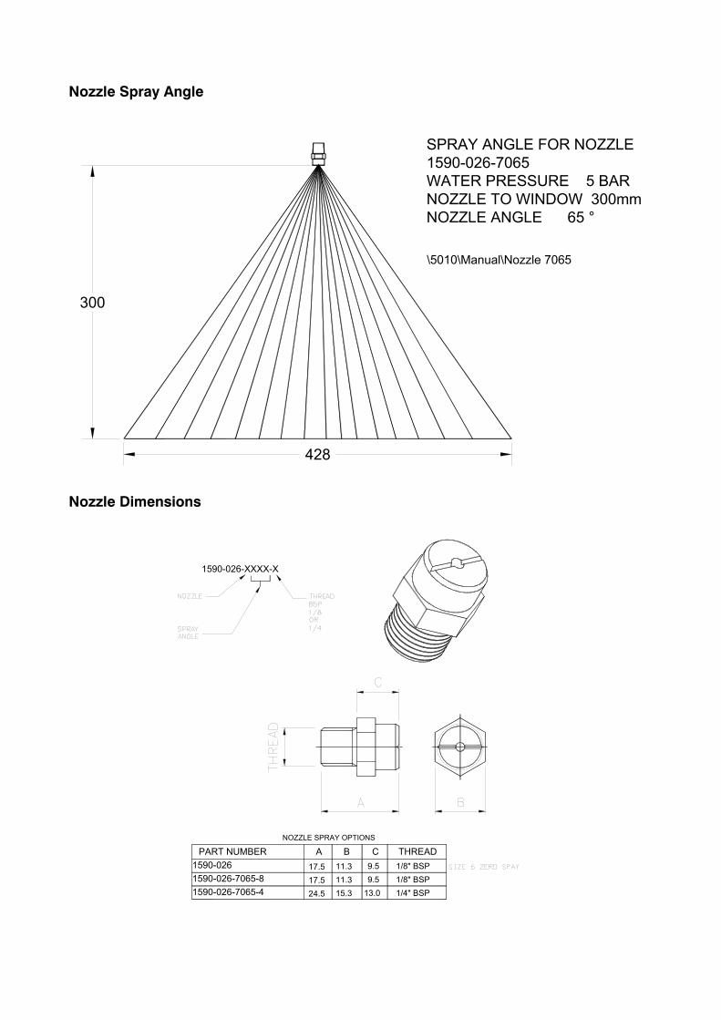
Nozzle Spray Angle
Nozzle Dimensions
428
SPRAY ANGLE FOR NOZZLE1590-026-7065WATER PRESSURE 5 BARNOZZLE TO WINDOW 300mmNOZZLE ANGLE 65 °
\5010\Manual\Nozzle 7065
300
1590-026 17.5 11.3 9.5 1/8" BSP9.517.5
A
11.3
B CNOZZLE SPRAY OPTIONS
1/8" BSP
THREAD
1590-026-7065-81590-026-7065-4 24.5 15.3 13.0 1/4" BSP
PART NUMBER
1590-026-XXXX-X
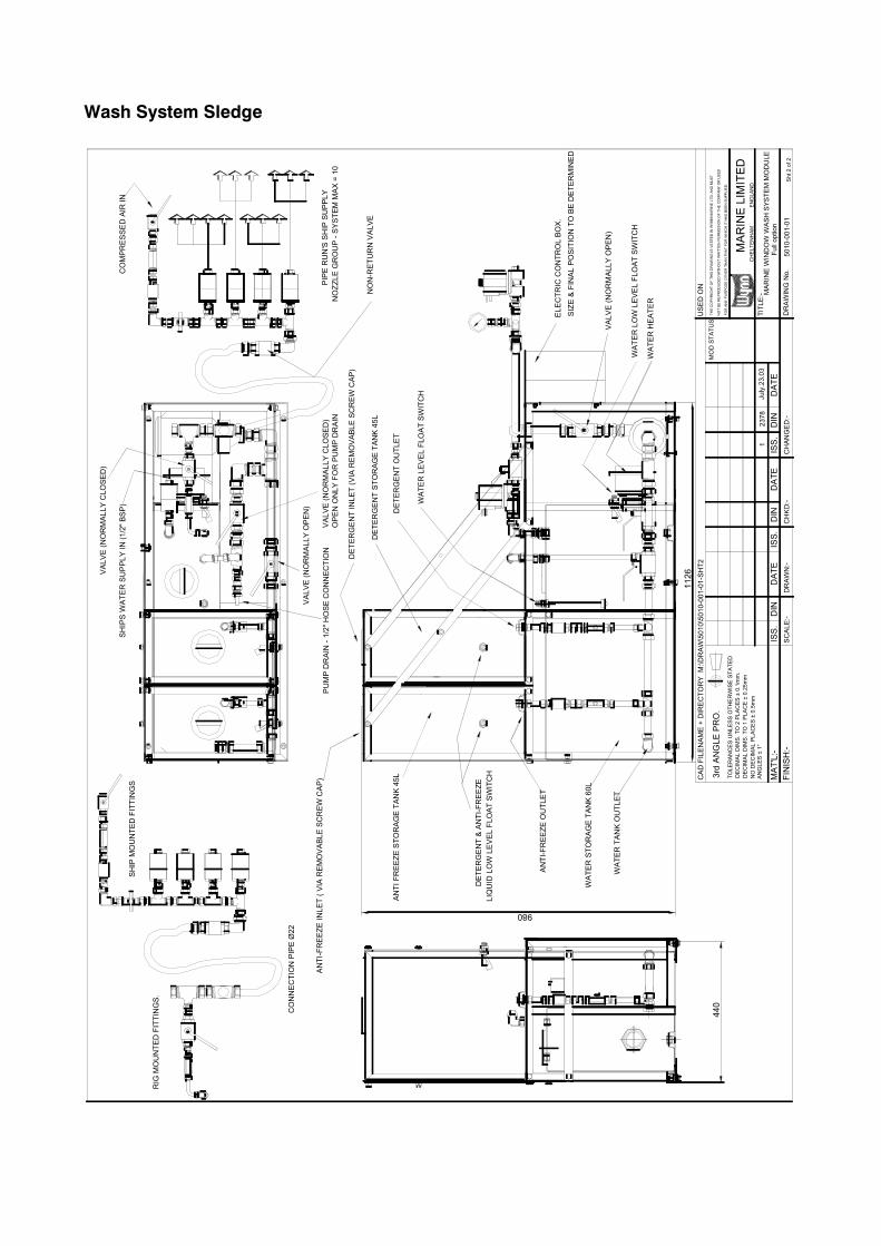
Wash System Sledge
MAR
INE
WIN
DO
W W
ASH
SYS
TEM
MO
DU
LEJu
ly.2
3.03
1
5010
-001
-01
2378
CH
KD:-
DIN
CAD
FIL
ENAM
E +
DIR
ECTO
RY
M:\D
RAW
\501
0\50
10-0
01-0
1-SH
T2
TOLE
RAN
CES
UN
LESS
OTH
ERW
ISE
STAT
EDD
ECIM
AL D
IMS.
TO
2 P
LAC
ES ±
0.1
mm
.D
ECIM
AL D
IMS.
TO
1 P
LAC
E ±
0.25
mm
NO
DEC
IMAL
PLA
CES
± 0
.5m
mA
NG
LES
± 1°
FIN
ISH
:-M
AT'L
:-
3rd
ANG
LE P
RO
.
SCAL
E:-
ISS.
DIN
DR
AWN
:-
DAT
EIS
S.
MAR
INE
LIM
ITED
CH
ELTE
NH
AM
E
NG
LAN
D
MO
D S
TATU
S
CH
ANG
ED:-
DAT
EIS
S.D
ATE
DIN
TITL
E:-
DR
AWIN
G N
o.
USE
D O
N
Full
optio
n
Sht 2
of 2
SHIP
S W
ATER
SU
PPLY
IN (1
/2" B
SP)
CO
MPR
ESSE
D A
IR IN
NO
ZZLE
GR
OU
P - S
YSTE
M M
AX =
10
PIPE
RU
N'S
SH
IP S
UPP
LYPU
MP
DR
AIN
- 1/
2" H
OSE
CO
NN
ECTI
ON
ANTI
FR
EEZE
STO
RAG
E TA
NK
45L
DET
ERG
ENT
STO
RAG
E TA
NK
45L
WAT
ER S
TOR
AGE
TAN
K 60
L
ELEC
TRIC
CO
NTR
OL
BOX.
LIQ
UID
LO
W L
EVEL
FLO
AT S
WIT
CH
DET
ERG
ENT
& AN
TI-F
REE
ZE
WAT
ER L
OW
LEV
EL F
LOAT
SW
ITC
H
WAT
ER L
EVEL
FLO
AT S
WIT
CH
WAT
ER H
EATE
R
WAT
ER T
ANK
OU
TLET
DET
ERG
ENT
OU
TLET
ANTI
-FR
EEZE
OU
TLET
DET
ERG
ENT
INLE
T (V
IA R
EMO
VABL
E SC
REW
CAP
)
ANTI
-FR
EEZE
INLE
T ( V
IA R
EMO
VABL
E SC
REW
CAP
)
RIG
MO
UN
TED
FIT
TIN
GS.
SHIP
MO
UN
TED
FIT
TIN
GS
CO
NN
ECTI
ON
PIP
E Ø
22
SIZE
& F
INAL
PO
SITI
ON
TO
BE
DET
ERM
INED
NO
N-R
ETU
RN
VAL
VE
VALV
E (N
OR
MAL
LY O
PEN
)
VALV
E (N
OR
MAL
LY C
LOSE
D)
OPE
N O
NLY
FO
R P
UM
P D
RAI
N
VALV
E (N
OR
MAL
LY C
LOSE
D)
VALV
E (N
OR
MAL
LY O
PEN
)
FOR
AN
Y PU
RPO
SE O
THER
TH
AN
THAT
FO
R W
HIC
H IT
HA
S BE
EN S
UPP
LIED
.
NO
T BE
RE
PRO
DU
CED
WIT
HO
UT
WRI
TTEN
PER
MIS
SIO
N O
F TH
E C
OM
PAN
Y O
R U
SED
THE
CO
PYR
IGH
T O
F TH
IS D
RAW
ING
IS V
ESTE
D IN
WYN
N M
ARIN
E LT
D. A
ND
MU
ST
440
980
1126
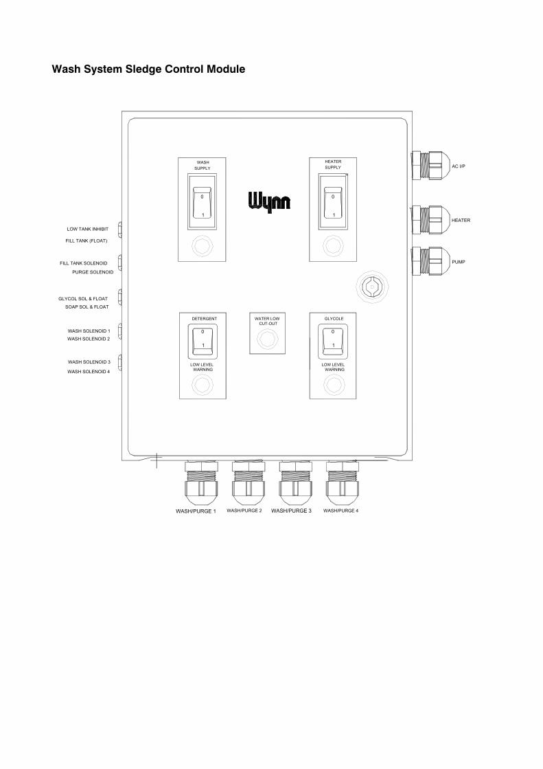
Wash System Sledge Control Module
GLYCOLE
LOW LEVELWARNING
1
0
SUPPLY SUPPLYWASH HEATER
WATER LOWDETERGENTCUT-OUT
LOW LEVELWARNING
1
0
LOW TANK INHIBIT
FILL TANK (FLOAT)
WASH/PURGE 2WASH/PURGE 1 WASH/PURGE 3 WASH/PURGE 4
HEATER
PUMP
AC I/P
FILL TANK SOLENOID
WASH SOLENOID 1
WASH SOLENOID 2
WASH SOLENOID 3
PURGE SOLENOID
WASH SOLENOID 4
SOAP SOL & FLOAT
GLYCOL SOL & FLOAT
1
0
1
0
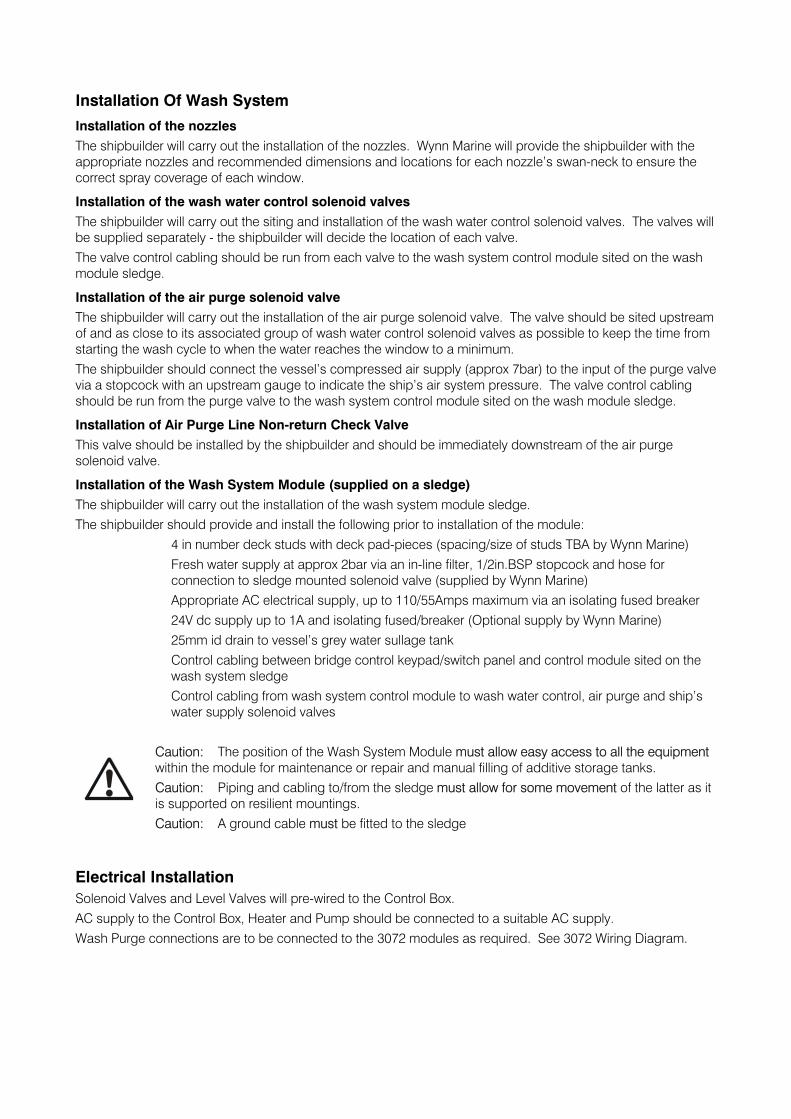
Installation Of Wash System
Installation of the nozzles The shipbuilder will carry out the installation of the nozzles. Wynn Marine will provide the shipbuilder with the appropriate nozzles and recommended dimensions and locations for each nozzle’s swan-neck to ensure the correct spray coverage of each window.
Installation of the wash water control solenoid valves The shipbuilder will carry out the siting and installation of the wash water control solenoid valves. The valves will be supplied separately - the shipbuilder will decide the location of each valve. The valve control cabling should be run from each valve to the wash system control module sited on the wash module sledge.
Installation of the air purge solenoid valve The shipbuilder will carry out the installation of the air purge solenoid valve. The valve should be sited upstream of and as close to its associated group of wash water control solenoid valves as possible to keep the time from starting the wash cycle to when the water reaches the window to a minimum. The shipbuilder should connect the vessel’s compressed air supply (approx 7bar) to the input of the purge valve via a stopcock with an upstream gauge to indicate the ship’s air system pressure. The valve control cabling should be run from the purge valve to the wash system control module sited on the wash module sledge.
Installation of Air Purge Line Non-return Check Valve This valve should be installed by the shipbuilder and should be immediately downstream of the air purge solenoid valve.
Installation of the Wash System Module (supplied on a sledge) The shipbuilder will carry out the installation of the wash system module sledge. The shipbuilder should provide and install the following prior to installation of the module: 4 in number deck studs with deck pad-pieces (spacing/size of studs TBA by Wynn Marine) Fresh water supply at approx 2bar via an in-line filter, 1/2in.BSP stopcock and hose for
connection to sledge mounted solenoid valve (supplied by Wynn Marine) Appropriate AC electrical supply, up to 110/55Amps maximum via an isolating fused breaker 24V dc supply up to 1A and isolating fused/breaker (Optional supply by Wynn Marine) 25mm id drain to vessel’s grey water sullage tank Control cabling between bridge control keypad/switch panel and control module sited on the
wash system sledge Control cabling from wash system control module to wash water control, air purge and ship’s
water supply solenoid valves
Caution: The position of the Wash System Module must allow easy access to all the equipment within the module for maintenance or repair and manual filling of additive storage tanks. Caution: Piping and cabling to/from the sledge must allow for some movement of the latter as it is supported on resilient mountings. Caution: A ground cable must be fitted to the sledge
Electrical Installation Solenoid Valves and Level Valves will pre-wired to the Control Box. AC supply to the Control Box, Heater and Pump should be connected to a suitable AC supply. Wash Purge connections are to be connected to the 3072 modules as required. See 3072 Wiring Diagram.
Maintenance Of The Wash System Equipment
General The Wash System will be used for very short and infrequent periods and therefore maintenance will consist mainly of inspection for corrosion and general deterioration rather than for wear. It is recommended that the following maintenance procedures be included in the overall ship’s planned maintenance system.
Nozzles Alignment and spray pattern of each nozzle should be checked weekly by operating the wash system and checking each nozzle’s performance. Misalignment could be caused by distortion of a swan-neck by a physical impact requiring re-alignment of the swan-neck. A poor spray pattern will be usually due to fouling of the nozzle orifice by the growth of natural organisms or by debris having passed through the piping and becoming trapped in the nozzle orifice.
Solenoid valves - wash water control, air purge, and ship’s water supply and anti-freeze and detergent additive control These valves are similar and require no maintenance other than a 12 monthly external inspection for signs of leaks, security of fastenings and loose connections.
Wash Pump The pump has pre-packed bearings and the only internal maintenance required should be an inspection of the mechanical seal and impellor every 24 months. The pump and adjacent piping, fastenings, etc should be inspected every 6 months for leaks, security and deterioration.
Wash Pump Motor The motor is an induction type and totally enclosed with pre-packed bearings. No maintenance should be necessary other than an external inspection every 6 months of mounting fastenings, electrical cabling and glands for security and deterioration.
Liquid Containers The containers are constructed of a non-corrodible material and their structure should require no maintenance. Security of piping connections, fastenings and cable connections, etc should be inspected every 6 months The 3 containers should be drained down every 12 months and internally inspected for deposits and growth of organisms. If any is found the container should be removed and rinsed with fresh water. Container screw caps and aperture seals should be examined for security and deterioration and renewed as necessary.
Immersion heater (if option is fitted)
Every 3 months Inspect the unit overall for leaks, fastener security and any deterioration.
Every 6 months Remove the terminal cover and check the box is dry and clean and that all connections are tight.
Every 12 months Check the element resistance is at least 2 megohms and check the continuity of all elements. Check and renew the cover gasket when necessary.
Caution: If the heater is not used for 3 months or longer, carry out the 3 and 6 monthly maintenance routines before use.
System valves (auto/hand operated) The following valves require no maintenance other than being worked through their full range and an inspection every 12 months for leaks, security of connections, glands, fastenings, etc:
Pump isolating valves (2) Non-return check valves (2) Anti-freeze metering valve (if option is fitted) Detergent metering valve (if option is fitted) Wash water tank drain valve Air bleeding valve
System piping and fittings The wash system module piping and associated fittings are made from non-corrodible materials and should require no maintenance other than an inspection every 12 months for leaks or deterioration, pipe connection and support fastening security, etc.
Wash System Fault Finding
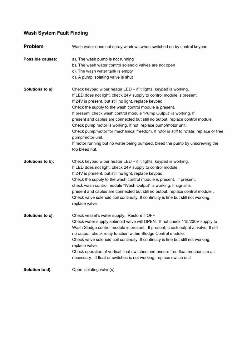
Problem – Wash water does not spray windows when switched on by control keypad Possible causes: a). The wash pump is not running b). The wash water control solenoid valves are not open c). The wash water tank is empty d). A pump isolating valve is shut Solutions to a): Check keypad wiper heater LED – if it lights, keypad is working. If LED does not light, check 24V supply to control module is present. If 24V is present, but still no light, replace keypad. Check the supply to the wash control module is present. If present, check wash control module “Pump Output” is working. If present and cables are connected but still no output, replace control module. Check pump motor is working. If not, replace pump/motor unit. Check pump/motor for mechanical freedom. If rotor is stiff to rotate, replace or free pump/motor unit. If motor running but no water being pumped, bleed the pump by unscrewing the top bleed nut. Solutions to b): Check keypad wiper heater LED – if it lights, keypad is working. If LED does not light, check 24V supply to control module. If 24V is present, but still no light, replace keypad. Check the supply to the wash control module is present. If present, check wash control module “Wash Output” is working. If signal is present and cables are connected but still no output, replace control module.. Check valve solenoid coil continuity. If continuity is fine but still not working, replace valve. Solutions to c): Check vessel’s water supply. Restore if OFF Check water supply solenoid valve will OPEN. If not check 115/230V supply to Wash Sledge control module is present. If present, check output at valve. If still no output, check relay function within Sledge Control module. Check valve solenoid coil continuity. If continuity is fine but still not working, replace valve. Check operation of vertical float switches and ensure free float mechanism as necessary. If float or switches is not working, replace switch unit Solution to d): Open isolating valve(s)
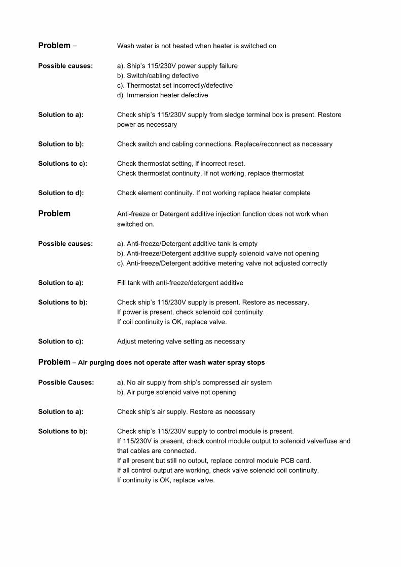
Problem – Wash water is not heated when heater is switched on Possible causes: a). Ship’s 115/230V power supply failure b). Switch/cabling defective c). Thermostat set incorrectly/defective d). Immersion heater defective Solution to a): Check ship’s 115/230V supply from sledge terminal box is present. Restore power as necessary Solution to b): Check switch and cabling connections. Replace/reconnect as necessary Solutions to c): Check thermostat setting, if incorrect reset. Check thermostat continuity. If not working, replace thermostat Solution to d): Check element continuity. If not working replace heater complete
Problem Anti-freeze or Detergent additive injection function does not work when switched on. Possible causes: a). Anti-freeze/Detergent additive tank is empty b). Anti-freeze/Detergent additive supply solenoid valve not opening c). Anti-freeze/Detergent additive metering valve not adjusted correctly Solution to a): Fill tank with anti-freeze/detergent additive Solutions to b): Check ship’s 115/230V supply is present. Restore as necessary. If power is present, check solenoid coil continuity. If coil continuity is OK, replace valve. Solution to c): Adjust metering valve setting as necessary
Problem – Air purging does not operate after wash water spray stops Possible Causes: a). No air supply from ship’s compressed air system b). Air purge solenoid valve not opening Solution to a): Check ship’s air supply. Restore as necessary Solutions to b): Check ship’s 115/230V supply to control module is present. If 115/230V is present, check control module output to solenoid valve/fuse and that cables are connected. If all present but still no output, replace control module PCB card. If all control output are working, check valve solenoid coil continuity. If continuity is OK, replace valve.
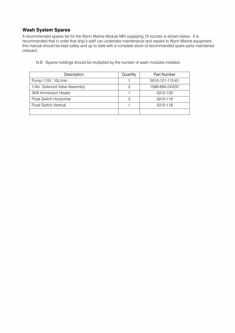
Wash System Spares A recommended spares list for the Wynn Marine Module MKI supplying 10 nozzles is shown below. It is recommended that in order that ship’s staff can undertake maintenance and repairs to Wynn Marine equipment, this manual should be kept safely and up to date with a complete stock of recommended spare parts maintained onboard. N.B. Spares holdings should be multiplied by the number of wash modules installed.
Description Quantity Part Number
Pump 115V, 10L/min 1 5010-121-115-61
1/4in Solenoid Valve Assembly 3 1588-694-24VDC
3kW Immersion Heater 1 5010-120
Float Switch Horizontal 3 5010-119
Float Switch Vertical 1 5010-118
Documentation
Whilst every effort is made to provide accurate information in good faith, no responsibility can be accepted by Wynn for inaccuracies and Wynn reserves the right to alter and amend specifications and designs without prior notice in line with our policy of continued improvement.
Spares Parts
To enable technical troubleshooting and ordering of spare parts, this manual should be kept in a safe place on board. It is also advisable to keep one set of spare parts on board for emergency use. Please contact Wynn directly or your local distributor / service centre for all order requirements.
Maintenance Schedules
Plan your maintenance work according to the schedule in this manual.
Our Commitment
We are committed to a 10 year product support programme. This ensures that any spare part will be available for any wiper at least 10 years after its purchase. It is strongly recommended that only genuine replacement parts manufactured by WYNN be used. This will guarantee that only suitable materials have been used and will ensure interchangeability of parts.
Quality and Testing
We are committed to the principles of Total Quality Management, ISO 9000. We manufacture our range of marine products to the highest standard and quality. We therefore maintain an ongoing schedule of product improvement and testing. To help us sustain such standards we maintain a salt-water test rig on which our products are taken, at random from the production line, and subjected to 3,000 hour continuous testing. We are sure you will receive many years trouble-free service from your Wynn product and hope you find this information pack comprehensive.
Guarantee
All Wynn equipment is tested before despatch from our works. The Windscreen Wiper System supplied has a 1 year warranty period provided the installation of the system and the subsequent maintenance is in accordance with the installation/maintenance instructions.
We cannot accept any responsibility for the installation of equipment, or damage to the equipment during installation, or normal wear and tear. The guarantee is negated if the equipment is not installed strictly observing the instructions set out in this manual, or not maintained as specified.
The Wiper System is very reliable but to ensure its continued smooth running we recommend that the following guidelines are adhered to:-
Monthly
• Check for wear on all parts subject to friction
• Visual inspection should be made of the blades to ensure that they are still in good condition and replace as soon as there are signs of ware or damage
Annually
• It is recommended that the blades are changed every 12 months
After the Wiper System has been operating in severe weather conditions it is advisable to thoroughly check the unit for signs of wear or damage.
This warranty excludes the wiper blades which are a consumable item and any replacements that are detailed in the manual as part of any regular maintenance requirement.
This guarantee is expressly in lieu of all other guarantees expressed or implied and of all other obligations of liabilities on our part, and we neither assume nor authorise any other person to assume for us any other liability in connection with the sale of our equipment. Faulty equipment must be returned, carriage paid, to our works for examination. Any legal action must be settled in the English courts under English law.
A worldwide network of agents supports Wynn’s Marine product range. For details of the nearest Wynn agent please contact our Head Office. Wynn Agents operate in the following countries.
Argentina, Australia, Brazil, Canada, Chile, China, Croatia, Denmark, Egypt, Finland, France, Germany, Greece, Hong Kong, Iceland, India, Israel, Italy, Japan, Korea, Netherlands, New Zealand, Norway, Oman, Peru, Poland, Portugal, Russia, Singapore, South Africa, Spain, Sweden, Taiwan, Turkey, Ukraine, U.S.A.
Wynn Marine Ltd
2-4 Merse Road, North Moons Moat, Redditch, Worcestershire B98 9HL
Tel: +44 (0) 1527 61243, Fax: +44 (0) 1527 66836
Email: [email protected], website www.wynn.co.uk