Embed Size (px)
Citation preview
ENGINEERING AND DEVELOPMENT GUIDELINES
WATER SUPPLY
STANDARD
Status : Consultation Edition – 14 October 2005
Incorporates the WSAA “Water Supply Code of Australia” (2002)

Calliope Shire Council
Revisied 17/10/2005
ii
(Blank Page)
Page 1
WATER SUPPLY STANDARD
Engineering and Development Guidelines – Water Supply Standard
Revised 17 October 2005
WATER RETICULATION STANDARD
These standards apply to the design and construction of water reticulation works for new development within Calliope Shire and Gladstone City.
The Water Services Association of Australia’s “Water Supply Code of Australia” - 2002 (WSCOA) forms a part of and is to be read as one with this Standard. This Standard gives the provisions required by Council over and above the “Water Supply Code of Australia” and some guidance in the use of the code. This “Water Supply Code of Australia” is now being adopted as default IPA code by the Queensland Government. The code can be obtained from the following sources:
Water Services Association of Australia Standards Australia 469 Latrobe Street 1 the Crescent Melbourne Victoria 3000 Homebush NSW 2140
This standard outlines Council's current requirements in relation to the provision of water reticulation works and departures from these requirements will only be permitted with the prior agreement of Council.
The distribution of this Standard does not limit Council's authority to impose additional or alternative requirements, if such requirements are warranted having regard to the particular circumstances of a subdivision and good engineering practice.
Where Australian Standards, By-laws, manufacturer's recommendations, or other publications are referred to in these guidelines, the latest revision of such documents shall be used.
Council has produced this standard to simplify the documentation of water reticulation projects. Standards from other authorities will not be accepted where a Council standard is available. Standard drawings have been produced to compliment these standards, a copy of which is available from the respective Council’s Offices. Consulting Engineers and Civil contractors should obtain a copy this water supply standard.
Any request for an alternative proposal to the requirements of this Standard must be made in writing to the Manager Water Services. This request must state the reasons and benefits of the alternative arrangement. Capital cost savings alone is not considered a suitable reason. Any approval for alternatives will only be permitted following the written confirmation of acceptance of the alternative.
Page 2
WATER SUPPLY STANDARD
Engineering and Development Guidelines – Water Supply Standard
Revised 17 October 2005
TABLE OF CONTENTS DESIGN............................................................................................................................................................................. 5 1 GENERAL................................................................................................................................................................. 5
1.1 OBJECTIVES OF WATER RETICULATION WORKS ..................................................................................................... 5 1.2 WATER AGENCY................................................................................................................................................... 5 1.3 RETICULATION SYSTEMS....................................................................................................................................... 6 1.4 PERSONNEL QUALIFICATIONS............................................................................................................................... 6
2 DESIGN OF LOCALISED NETWORK ................................................................................................................... 7 2.1 PREFERRED MAIN SIZES....................................................................................................................................... 8 2.2 ENVIRONMENTAL CONTROLS ................................................................................................................................ 8
3 DESIGN OF DISTRIBUTION WORKS ................................................................................................................... 8 4 PIPELINE DESIGN................................................................................................................................................... 8
4.1 LOCATION AND ALIGNMENT ................................................................................................................................. 8 4.1.1 Shared Trenches .............................................................................................................................................................9 4.1.2 Bends and Curves ...........................................................................................................................................................9 4.1.3 Intersections ...................................................................................................................................................................9 4.1.4 Cul-de-sacs and cul-de-sac roads.................................................................................................................................10
4.2 HYDRAULIC DESIGN .......................................................................................................................................... 11 4.3 STRUCTURAL DESIGN......................................................................................................................................... 11
4.3.1 Embedment & Cover.....................................................................................................................................................11 4.3.2 Pipe Anchorage ............................................................................................................................................................12 4.3.3 Bulkheads And Trench Stops ........................................................................................................................................12
4.4 OPERATIONAL FACILITIES (RESERVIORS, PUMPS ETC).......................................................................................... 12 4.4.1 Pumping Stations..........................................................................................................................................................12 4.4.2 Service Storage.............................................................................................................................................................12 4.4.3 Provision of Pumping Stations and Service Storage by the Developer ........................................................................12
4.5 OBSTRUCTIONS AND CLEARANCES TO MAINS ...................................................................................................... 13 4.6 WATER QUALITY ................................................................................................................................................ 13 4.7 VALVES AND HYDRANTS ..................................................................................................................................... 13
4.7.1 Service Valves...............................................................................................................................................................13 4.7.2 Fire Hydrants ...............................................................................................................................................................14 4.7.3 Raised Pavement Markers for Valves and Hydrants ....................................................................................................14 4.7.4 Marker Posts ................................................................................................................................................................15 4.7.5 Air Valves And Scour Valves ........................................................................................................................................15
4.8 WATER SERVICE CONDUITS................................................................................................................................ 15 4.9 SERVICE CONNECTIONS TO MAINS – GLADSTONE CITY........................................................................................ 16
4.9.1 Tapping Bands..............................................................................................................................................................16 4.9.2 Commercial Developments Services.............................................................................................................................16 4.9.3 Commercial water connections ....................................................................................................................................16
4.10 SERVICE CONNECTIONS TO MAINS – CALLIOPE SHIRE ......................................................................................... 17 4.10.1 Tapping Bands..............................................................................................................................................................17 4.10.2 Pipe...............................................................................................................................................................................17 4.10.3 Water Service Fittings ..................................................................................................................................................17 4.10.4 Non-Residential Water Service Connections ................................................................................................................18
4.11 METERING PITS ................................................................................................................................................. 18 4.12 ZONE METERS ................................................................................................................................................... 18 4.13 PRESSURE ZONES............................................................................................................................................... 18
5 DRAWINGS ............................................................................................................................................................ 18 5.1 GENERAL REQUIREMENTS .................................................................................................................................. 18
5.1.1 Title blocks ...................................................................................................................................................................18 5.1.2 Layout Plans.................................................................................................................................................................19 5.1.3 "As Constructed" Information ......................................................................................................................................19
MATERIALS.................................................................................................................................................................. 20 6 PIPES......................................................................................................................................................................... 20 7 VALVES .................................................................................................................................................................... 21 8 HYDRANTS................................................................................................................................................................ 21 9 FITTINGS ................................................................................................................................................................... 21 10 ACID SULPHATE SOIL................................................................................................................................................ 22
Page 3
WATER SUPPLY STANDARD
Engineering and Development Guidelines – Water Supply Standard
Revised 17 October 2005
11 WATER SERVICES ..................................................................................................................................................... 22 11.1 CONDUITS ......................................................................................................................................................... 22 11.2 TAPPING BANDS................................................................................................................................................. 22 11.3 PIPE.................................................................................................................................................................. 22 11.4 FITTINGS ........................................................................................................................................................... 22 11.5 ACCESS CHAMBERS............................................................................................................................................ 22
12 MARKER POSTS......................................................................................................................................................... 23 13 TRENCH BACKFILL ................................................................................................................................................... 23
13.1 EMBEDMENT MATERIAL ..................................................................................................................................... 23 13.2 CONCRETE & STABILISED SAND ......................................................................................................................... 23
14 RAISED PAVEMENT MARKERS .................................................................................................................................. 23 CONSTRUCTION ......................................................................................................................................................... 25 15 GENERAL............................................................................................................................................................... 25 16 QUALITY................................................................................................................................................................ 25
16.1 PERSONNEL ....................................................................................................................................................... 25 16.2 ACCEPTANCE TESTING ....................................................................................................................................... 25
17 GENERAL CONSTRUCTION ............................................................................................................................... 25 18 MATERIALS........................................................................................................................................................... 25 19 EXISTING SERVICES............................................................................................................................................ 26 20 EXCAVATION ....................................................................................................................................................... 26
20.1 EXCAVATION...................................................................................................................................................... 26 20.2 EXCAVATION ACROSS IMPROVED SURFACES ....................................................................................................... 26
20.2.1 Sealed Roads ................................................................................................................................................................26 20.2.2 Gravel Roads ................................................................................................................................................................26 20.2.3 Driveways and Footpaths .............................................................................................................................................27
21 FILLING .................................................................................................................................................................. 27 22 COMPACTION ............................................................................................................................................................ 27 23 PIPE EMBEDMENT ............................................................................................................................................... 28 24 LAYING & JOINING.............................................................................................................................................. 29
24.1 LAYING AND JOINTING METHOD......................................................................................................................... 29 24.2 THRUST BLOCKS ................................................................................................................................................ 29 24.3 TRENCH STOPS .................................................................................................................................................. 29 24.4 BULKHEADS....................................................................................................................................................... 29 24.5 CORROSION PROTECTION................................................................................................................................... 29 24.6 DETECTABLE TAPE ............................................................................................................................................ 30 24.7 VALVES AND HYDRANTS ..................................................................................................................................... 30 24.8 BORED PIPES UNDER ROADS ETC....................................................................................................................... 30 24.9 AQUEDUCTS ...................................................................................................................................................... 30 24.10 LOCATION MARKERS.......................................................................................................................................... 30 24.11 WATER SERVICES – CSC ONLY ........................................................................................................................... 30
24.11.1 Conduits........................................................................................................................................................................31 24.11.2 Pipes .............................................................................................................................................................................31 24.11.3 Tapping Band and Ferrule Cock ..................................................................................................................................31 24.11.4 Fittings .........................................................................................................................................................................31 24.11.5 Access Chambers..........................................................................................................................................................31
25 ACCESS CHAMBERS............................................................................................................................................ 32 26 TOLERANCES ON "AS CONSTRUCTED" WORK ............................................................................................................ 32
26.1 HORIZONTAL TOLERANCES........................................................................................................................ 32 26.1.1 21.2.1 Water mains and in-line structures....................................................................................................................32 26.1.2 21.2.2 Property services and meters.............................................................................................................................32
26.2 VERTICAL TOLERANCES.............................................................................................................................. 32 26.2.1 Water mains, property connections and structures ......................................................................................................32 26.2.2 Verticality ("plumb") ....................................................................................................................................................32
26.3 TOLERANCES ON FINISHED SURFACE STRUCTURES AND FITTINGS .................................................. 33 27 BACKFILLING ....................................................................................................................................................... 33 28 DISINFECTION ...................................................................................................................................................... 33
28.1 FLUSHING & CHLORINATION.............................................................................................................................. 33 29 CONNECTION TO EXISTING MAINS................................................................................................................. 34 30 RESTORATION & CLEAN UP .............................................................................................................................. 35
30.1 STORMWATER QUALITY ..................................................................................................................................... 35
Page 4
WATER SUPPLY STANDARD
Engineering and Development Guidelines – Water Supply Standard
Revised 17 October 2005
30.2 EROSION PROTECTION ....................................................................................................................................... 35 30.3 HYDRANT & VALVE MAINTENANCE..................................................................................................................... 35
31 WORKS AS CONSTRUCTED INFORMATION ..................................................................................................... 35 32 PROCEDURAL REQUIREMENTS........................................................................................................................ 36
32.1 DESIGN CHECK LISTS ........................................................................................................................................ 36 32.2 INSPECTION AUDITS........................................................................................................................................... 36 32.3 INSPECTIONS ..................................................................................................................................................... 36 32.4 CERTIFICATION BY SUPERVISING CONSULTING ENGINEER................................................................................... 37 32.5 MAINTENANCE PERIOD ...................................................................................................................................... 37
33 WATER FOR CONSTRUCTION ..................................................................................................................................... 38 33.1 BACK FLOW PREVENTION .................................................................................................................................. 39 33.2 REGISTERED STANDPIPES (CSC ONLY)............................................................................................................... 40
34 WATER FOR LANDSCAPING PURPOSES........................................................................................................................ 40 STANDARD DRAWINGS............................................................................................................................................. 41
APPENDIX A – STANDARD DRAWINGS ................................................................................................................ 45
Page 5
WATER SUPPLY STANDARD
Engineering and Development Guidelines – Water Supply Standard
Revised 17 October 2005
DESIGN
1 GENERAL
The design and construction of water supply infrastructure will generally be in accordance with the Water Services Association of Australia’s “Water Supply Code of Australia” (WSCOA) and the relevant Australian Standards, as amended by this Standard and standard drawings which take precedence over the WSCOA. The "Guidelines for the Planning and Design of Urban Water Supply Schemes" may be referenced by Council from time to time.
Construction of “domestic” water infrastructure will require considerable reference to this standard as this is the predominant type of mains laid. The configuration of larger reticulation mains is expected to follow the WSCOA more closely.
In order of preference of compliance, water reticulation systems shall be provided in accordance with the following documents and their priority:
1. Water Supply Standard 2004
2. WSCOA
3. Component manufacturer’s specifications.
Only where a specific item is not covered in the previous document, shall the next document be referred to.
Where uncertainty exists due to conflict between these documents, Council advice should be sought. Any deviation from these specifications shall only be permitted with approval of the relevant Water System Manager. Other requirements may be prescribed in the conditions of the Development Permit for the development. These should be included in the check list of any quality system for development works.
Where this document refers to a drawing WAT-XXXX, it is referring to specific a drawing in WSCOA.
1.1 OBJECTIVES OF WATER RETICULATION WORKS The objectives of water supply construction in both Councils is to provide a high quality, low maintenance, minimal water loss system produced to a high level of workmanship which will provide the rate payers with an efficient system which requires a minimum of stores inventory for repair works.
1.2 WATER AGENCY The Water Agency for water reticulation works within the Calliope Shire is the Calliope Shire Council and within Gladstone City Council is Gladstone City Council.
Page 6
WATER SUPPLY STANDARD
Engineering and Development Guidelines – Water Supply Standard
Revised 17 October 2005
1.3 RETICULATION SYSTEMS Council has town pressure reticulation systems in the larger centres with Master Plans guiding the direction of new reticulation systems. Each system will have a service level for which water supply is guaranteed. The minimum and maximum mains pressure for residential zones is 250kPa and 800kPa respectively. The minimum and maximum mains pressure for industrial/commercial properties is 320 kPa and 800 kPa respectively.
In some designated rural areas, Calliope Shire Council may consider constant flow water reticulation systems. The requirements for the constant flow system are somewhat different to the full mains pressure systems and as such Council will generally determine the design of the network. Constant flow systems do not have fire fighting capability.
Gladstone City Council does not permit the use of Trickle Flow Systems.
1.4 PERSONNEL QUALIFICATIONS Design of Water Reticulation is required to be undertaken by Engineers who hold a current Registration Certificate as a Registered Professional Engineer of Queensland, Area: Civil.
The engineer must be experienced in the design of Water Reticulation.
All submitted plans must be appropriately ‘signed off’ by the designing and certifying engineer and contain the RPEQ number of the certifying engineer.
Page 7
WATER SUPPLY STANDARD
Engineering and Development Guidelines – Water Supply Standard
Revised 17 October 2005
2 DESIGN OF LOCALISED NETWORK
Council will have already analysed most of the localised water supply network for the developed areas of Council and has prepared a “Master Plan / Water Supply Planning Report” for water reticulation indicating pipe sizes and connections which will be required at particular locations in order to provide a satisfactory standard of service to the community.
Fire flows of 15l/s for residential areas and 30l/s for commercial/industrial areas will be required to be sustained in the pipe network analysis. Additional requirements may be required within the network to comply with fire flows required in accordance with the building regulations for high density commercial/industrial development.
Developers may be eligible for “over-sizing payments” where larger water mains are required through a development which are significantly larger than determined by the demand of the development. Mains over 150mm diameter may be eligible for oversize payments. From recent modelling results, it is generally expected that the minimum size of mains will be 150mm diameter, in order to achieve fire fighting flows.
Where a development incorporates a staging process, a Consulting Engineer shall submit a Master Plan of the water reticulation showing proposed main sizes, connections to existing mains and valve positions. The Master Plan will be supported by a computer network analysis, undertaken utilising approved software.
Council generally requires a looped network with at least two separate supply mains into each residential, commercial or industrial estate. Designers should aim to achieve this requirement wherever possible when preparing the Master Plan. In the case of a staged development, each stage must facilitate the two feed looping for future stages.
Water reticulation mains shall be a minimum size of 100mm diameter in residential developments and 150mm diameter in commercial, industrial, and high density residential developments. Commercial and industrial developments shall be provided with a main on each side of the road reserve to eliminate the requirement for service crossings.
Trickle feed systems at the end of a line with long lengths of mains between services may use a smaller main size to reduce the time as approved by CSC.
Supply mains of 250mm diameter and larger shall be classed a trunk mains and no service connections shall be permitted on these mains. A smaller diameter reticulation main shall be provided parallel to trunk mains where required to provide house supply services.
The Master Plan is to be submitted prior to, or at the same time as, submission of engineering drawings for the first stage of works. If at any time during the progress of the development, variations to Lot Layout, road alignment or other reasons affect the development to the extent that the original Master Plan ceases to become accurate, a revised Master Plan is to be submitted.
Cul-de-sac water mains are required to be installed as per the requirements of the standard drawing (WDS-05). This follows the requirements of the layout as per section 4.1.4 Cul-de-sacs and cul-de-sac roads.
Page 8
WATER SUPPLY STANDARD
Engineering and Development Guidelines – Water Supply Standard
Revised 17 October 2005
2.1 PREFERRED MAIN SIZES Preferred pipe sizes are 100mm, 150mm, 200mm 250mm and 300mm. Mains of 225mm diameter are not acceptable, as these are permissible only for sewerage rising mains. Section 2.3.1.1 of WSCOA with respect to minimum sizes applies.
For the minimum class of pipe and fittings to be used, please refer to “Materials” Sections 1 to 4.
2.2 ENVIRONMENTAL CONTROLS Where the installation of water facilities involves the disturbance of soil, a stormwater management plan will be required to be submitted as a part of the works showing how erosion and sedimentation from the construction will be controlled from breaking the earth, to stockpile control to restoration of disturbed, susceptible or loose ground.
3 DESIGN OF DISTRIBUTION WORKS
Unless otherwise agreed, Council will provide the concept plan for the distribution network.
Peak flow parameters shall be as supplied by Council based on the characteristics of the water reticulation system being designed for. Where peak flows are not known for a particular use, Table 2.1 of the WSCOA can be used in consultation with Council.
Fire fighting demand shall be included in the analysis simultaneously with the maximum demand and the maximum day flows for urban and commercial areas. Fire fighting flows to be analysed are as follows:
Urban 15 litres/sec, 2 hours
Commercial 30 litres/sec, 4 hours
For high density or integrated urban development, higher fire fighting flows will be required by Council. In this case, the fire fighting requirements will need to be negotiated through an approved fire safety engineering brief in accordance with the "Fire Safety Engineering Guidelines" (ABCB 2001).
For information on pressure zones, storage design, pump stations, and pressure criteria, please consult with Council staff.
4 PIPELINE DESIGN
4.1 LOCATION AND ALIGNMENT Water mains shall be located within existing or proposed road reserves, preferably on the opposite side to electricity and telecommunication services, and shall run parallel to the front property boundary on an alignment determined by the Std Drawings of the Roads and Transport Standard. The alignment at the time of publication is 1.5 metres from the property boundary.
Page 9
WATER SUPPLY STANDARD
Engineering and Development Guidelines – Water Supply Standard
Revised 17 October 2005
Trunk mains (250mm diameter and larger) shall be constructed on an alignment 4.8 metres from and parallel to the property boundary. If the verge width forces the main into the road carriageway, the designer should consult with Council with respect to variations of service alignments and road ways within road reserves, consider a wider road reserve, or another variation which must be approved by Council. Trunk mains must be located to minimise damage by flooding should a main break (ie located on the uphill verge of the road).
The network configuration of water mains should be a ring main with interconnecting branches where practical. Council’s preferred configurations for water mains in order of preference are as per Figure 4.3 of WSCOA.
4.1.1 Shared Trenches Water assets are not permitted to be installed in shared trenches.
4.1.2 Bends and Curves If the radius of curvature of the property alignment adjacent to the main is less than 60 metres, bends of an appropriate angle shall be used at changes in direction of the property boundary to maintain the required offset for the water main from the property boundary.
If the radius of curvature of the property alignment is greater than 60 metres, a maximum joint deflection of 80% of manufacturer’s specification may be used to allow the water main to generally remain on the required alignment. Shorter 4m lengths of pipe may be used to achieve this.
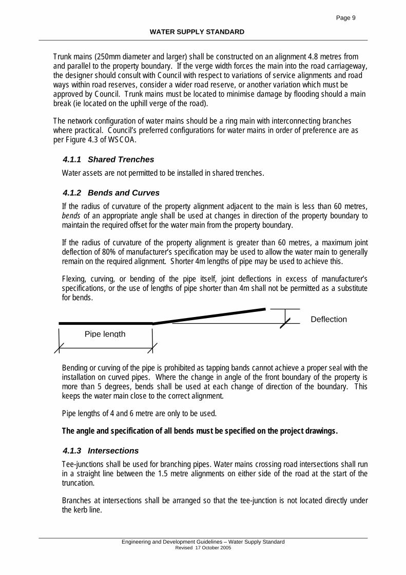
Flexing, curving, or bending of the pipe itself, joint deflections in excess of manufacturer’s specifications, or the use of lengths of pipe shorter than 4m shall not be permitted as a substitute for bends.
Bending or curving of the pipe is prohibited as tapping bands cannot achieve a proper seal with the installation on curved pipes. Where the change in angle of the front boundary of the property is more than 5 degrees, bends shall be used at each change of direction of the boundary. This keeps the water main close to the correct alignment.
Pipe lengths of 4 and 6 metre are only to be used.
The angle and specification of all bends must be specified on the project drawings.
4.1.3 Intersections Tee-junctions shall be used for branching pipes. Water mains crossing road intersections shall run in a straight line between the 1.5 metre alignments on either side of the road at the start of the truncation.
Branches at intersections shall be arranged so that the tee-junction is not located directly under the kerb line.
Pipe length
Deflection
Page 10
WATER SUPPLY STANDARD
Engineering and Development Guidelines – Water Supply Standard
Revised 17 October 2005
Class 35 DICL pipe must be utilised under kerbs and road pavements. This must extend a minimum of 0.5 metres behind the kerb into the footpath area.
4.1.4 Cul-de-sacs and cul-de-sac roads. Bends of an appropriate angle shall be used at each change in direction of the property boundary.
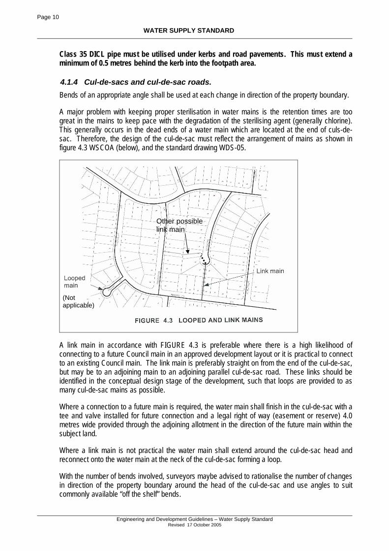
A major problem with keeping proper sterilisation in water mains is the retention times are too great in the mains to keep pace with the degradation of the sterilising agent (generally chlorine). This generally occurs in the dead ends of a water main which are located at the end of culs-de-sac. Therefore, the design of the cul-de-sac must reflect the arrangement of mains as shown in figure 4.3 WSCOA (below), and the standard drawing WDS-05.
A link main in accordance with FIGURE 4.3 is preferable where there is a high likelihood of connecting to a future Council main in an approved development layout or it is practical to connect to an existing Council main. The link main is preferably straight on from the end of the cul-de-sac, but may be to an adjoining main to an adjoining parallel cul-de-sac road. These links should be identified in the conceptual design stage of the development, such that loops are provided to as many cul-de-sac mains as possible.
Where a connection to a future main is required, the water main shall finish in the cul-de-sac with a tee and valve installed for future connection and a legal right of way (easement or reserve) 4.0 metres wide provided through the adjoining allotment in the direction of the future main within the subject land.
Where a link main is not practical the water main shall extend around the cul-de-sac head and reconnect onto the water main at the neck of the cul-de-sac forming a loop.
With the number of bends involved, surveyors maybe advised to rationalise the number of changes in direction of the property boundary around the head of the cul-de-sac and use angles to suit commonly available “off the shelf” bends.
Other possible link main
(Not applicable)
Page 11
WATER SUPPLY STANDARD
Engineering and Development Guidelines – Water Supply Standard
Revised 17 October 2005
4.2 HYDRAULIC DESIGN As part of the Water Authority’s responsibilities for management of the water reticulation network, a network analysis (model) of the water reticulation network is prepared to form the basis for the “Master Plans” or “Water Supply Planning Reports” for the reticulated areas of the Councils.
Where the land use or population density for the development is as assumed in the model and the Water Authority has a network analysis model available, hydraulic design of the water reticulation system will not be required (as per Section 2.2 of the WSCOA) unless specified by Council. The water mains in this case must be as per the diameters and configuration adopted in the model.
The proposed water reticulation system for areas outside of the modelled network area must be modelled to establish that the development provides an appropriate level of service to its residents and maintains an appropriate level of service to the existing network from which it draws from.
To save time and money, consultants may request permission from Council to utilise an existing network model (if available) which may be altered to model the existing and proposed network and establish measures required to provide the appropriate level of service to both networks. This work must be run by Council at cost to the developer.
4.3 STRUCTURAL DESIGN The designing engineer should consider the parameters as set out in Section 5 of WSCOA with respect to loading and geotechnical in the specification of the pipeline.
For ease of maintenance and reduction of stores and repair crew inventories, Council requires that PVC, Series 2 pipe with a minimum class 16 rating be used, unless:
- according to the appropriate standards, the application of the pipe requires a different type or greater pressure class be used; or
- Ductile Iron Cement lined pipe is being used under the roads; or - Polyethylene pipe is used in Calliope’s constant flow water system. The PVC pipe used must comply with WSAA’s 10 000 stiffness rating.
4.3.1 Embedment & Cover Water mains of 200mm diameter or less shall have a minimum cover of 750mm under roadways and kerbs, and 600mm elsewhere. During the construction of a road, a minimum of 600mm cover to subgrade is required such that construction loadings do not detrimentally affect the pipe. Acceptable tolerances in the depth of cover over the pipe may be from 0mm to +200mmm from the above depths. Trunk mains require 1200mm cover in all locations. Embedment shall be generally in accordance with WAT-1201 and Council Standard Drawings. Details shall be provided with the design drawings where the depth of water main will be varied to suit other services or impediments.
Embedment material (bedding sand) with a depth greater than 200mm shall be placed above the pipe in all instances.
4.3.2 Pipe Anchorage Thrust blocks shall be installed at all horizontal and vertical changes in direction of the water flow in the pipe.
Page 12
WATER SUPPLY STANDARD
Engineering and Development Guidelines – Water Supply Standard
Revised 17 October 2005
Thrust blocks for hydrants and valves and vertical bends shall be designed in accordance with WAT-1207.
Anchor/Thrust blocks for tees, reducers and horizontal bends shall be designed in accordance with WAT-1205. Restrained joint systems shall be designed in accordance with WAT – 1208. The use of this system must be appropriately marked on plans and in ground.
4.3.3 Bulkheads And Trench Stops Trench stops are usually not required by Council in the construction of water mains, however, pipes on grades steeper than 15% will require the installation of the bulkheads as per WCOA standard drawing WAT-1209.
4.4 OPERATIONAL FACILITIES (RESERVIORS, PUMPS ETC) Service storages and pumping stations are often included in the developer contributions (ie headworks PIPS etc) depending on the size and location of the development.
For large developments outside of the water service area, these facilities will most likely be provided at full cost to the developer unless some agreement is arranged with the Council. Water quality could also be a consideration for remote developments, with measures required to be provided to ensure correct levels of disinfection in the mains.
4.4.1 Pumping Stations Pumping stations should be generally avoided and the system designed to operate under gravity where possible. Pump stations are only permitted for pumping to reservoirs through trunk mains. Council does not permit the pressurising of mains by pump stations to directly service allotments in lieu of providing a reservoir.
4.4.2 Service Storage The size and location of service storages will be determined by Council within the water service area from the network analysis and the Master Plan. For large developments outside of the water service area, the provision of such facilities must be in close consultation with Council.
4.4.3 Provision of Pumping Stations and Service Storage by the Developer Council has no written standard for the design and construction of service storages or pumping stations as they are rare in communities of this size and mostly constructed by Council.
The design of any such facility will need to be carried out in close consultation with the Council such that the maintenance and operation of such facilities minimises operating costs and easily fit within the Council’s maintenance and service regimes.
The Developer may appoint a Consulting Engineer with experience and qualifications acceptable to Council to design the pump station in close consultation with Council, or request Council provide a quotation to design the pumping station at the expense of the Developer in consultation with the Developer’s Consulting Engineer.
Page 13
WATER SUPPLY STANDARD
Engineering and Development Guidelines – Water Supply Standard
Revised 17 October 2005
4.5 OBSTRUCTIONS AND CLEARANCES TO MAINS All underground obstructions and services and surface obstructions and structures along the proposed water main route must be treated in accordance with Section 4.10 of the WSCOA in the design and construction phase of the project.
Table 4.1 of the WSCOA outlines the clearances between water mains and under ground services. Lesser clearances will be considered based on the mitigation of influence and effects the service has on the water main and vice versa. Where water mains are to deviate around the other structure, the use of bends shall be strictly enforced. Joint deflect is not permitted.
The influence of the main on the zone of influence of the footing of an adjoining building and vice versa must be considered in accordance with Section 4.10.4 of the WSCOA.
4.6 WATER QUALITY Drinking water supply systems should be designed to maintain water quality in accordance with the “Australian Drinking Water Guidelines” by the incorporation of loop mains, measures for easy flushing of mains and minimisation of dead ends.
4.7 VALVES AND HYDRANTS Valves and hydrants must be provided in accordance with the following sections. Other types of valves may be required for the functioning of the network as specified by the Water Authority.
4.7.1 Service Valves Two valves shall be provided at every tee-junction to allow either branch to be isolated independently of the other. Valves shall be located within the footpath and if possible, in line with property boundaries. Council in certain situations may require more than two valves at a junction.
Council shall be consulted to identify the mains at the junction on which the valves shall be located. This will be based on the optimum situation for minimising disruptions to customers during maintenance activities.
All valves should be anticlockwise closing with a resilient seat, refer “Materials” section of this standard for more details of valves.
Valve covers shall be in accordance with WAT-1304, Type H1
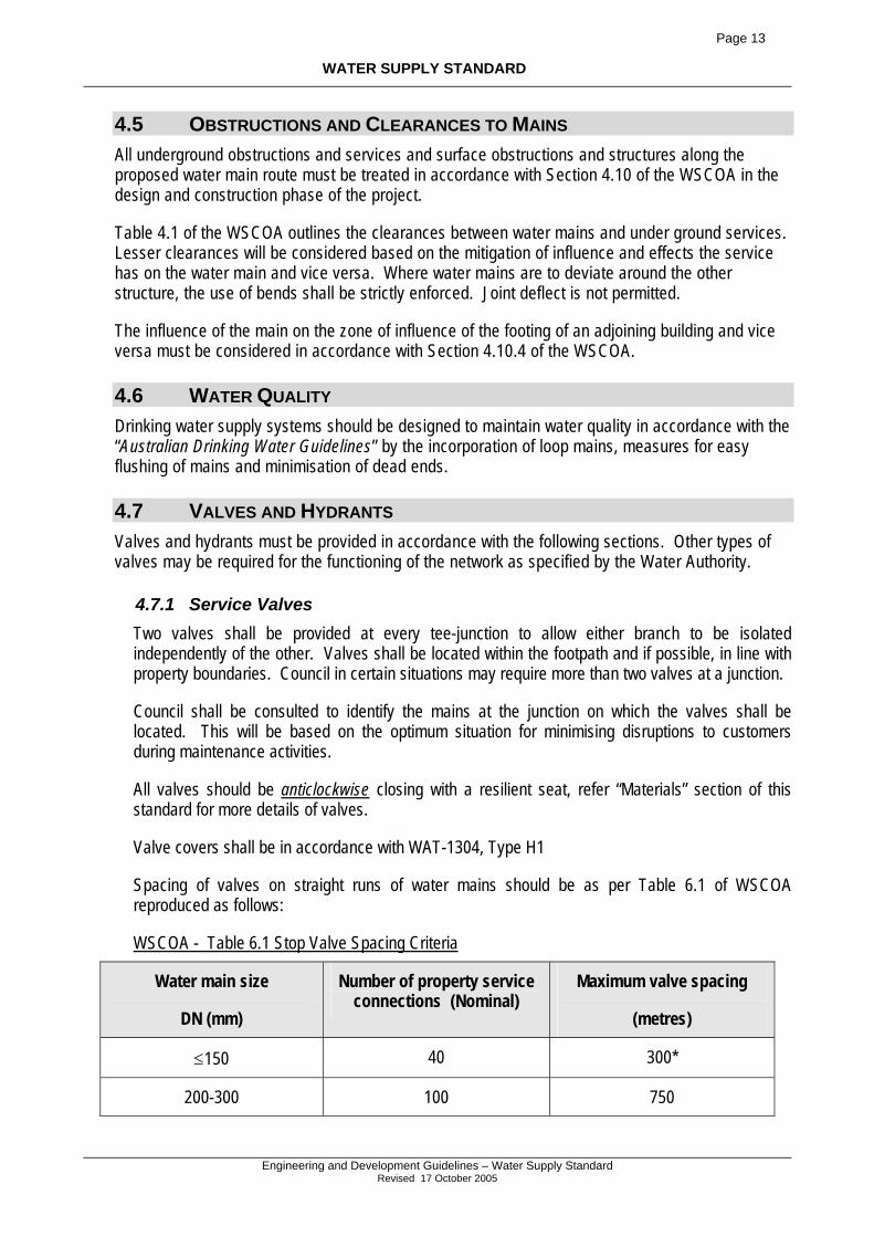
Spacing of valves on straight runs of water mains should be as per Table 6.1 of WSCOA reproduced as follows:
WSCOA - Table 6.1 Stop Valve Spacing Criteria
Water main size
DN (mm)
Number of property service connections (Nominal)
Maximum valve spacing
(metres)
≤150 40 300*
200-300 100 750
Page 14
WATER SUPPLY STANDARD
Engineering and Development Guidelines – Water Supply Standard
Revised 17 October 2005
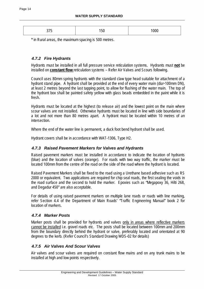
375 150 1000
* in Rural areas, the maximum spacing is 500 metres.
4.7.2 Fire Hydrants Hydrants must be installed in all full pressure service reticulation systems. Hydrants must not be installed on constant flow reticulation systems – Refer Air Valves and Scours following.
Council uses 80mm spring hydrants with the standard claw type head suitable for attachment of a hydrant stand pipe. A hydrant shall be provided at the end of every water main (dia>100mm DN), at least 2 metres beyond the last tapping point, to allow for flushing of the water main. The top of the hydrant box shall be painted safety yellow with glass beads embedded in the paint while it is fresh.
Hydrants must be located at the highest (to release air) and the lowest point on the main where scour valves are not installed. Otherwise hydrants must be located in line with side boundaries of a lot and not more than 80 metres apart. A hydrant must be located within 10 metres of an intersection.
Where the end of the water line is permanent, a duck foot bend hydrant shall be used.
Hydrant covers shall be in accordance with WAT-1306, Type H2.
4.7.3 Raised Pavement Markers for Valves and Hydrants Raised pavement markers must be installed in accordance to indicate the location of hydrants (blue) and the location of valves (orange). For roads with two way traffic, the marker must be located 100mm from the centre of the road on the side of the road where the hydrant is located.
Raised Pavement Markers shall be fixed to the road using a Urethane based adhesive such as RS 2000 or equivalent. Two applications are required for chip seal roads, the first sealing the voids in the road surface and the second to hold the marker. Epoxies such as “Megapoxy 36, Hilti 268, and Degadur 450” are also acceptable.
For details of using raised pavement markers on multiple lane roads or roads with line marking, refer Section 4.4 of the Department of Main Roads’ “Traffic Engineering Manual” book 2 for location of markers.
4.7.4 Marker Posts Marker posts shall be provided for hydrants and valves only in areas where reflective markers cannot be installed i.e. gravel roads etc. The posts shall be located between 100mm and 200mm from the boundary directly behind the hydrant or valve, preferably located and orientated at 90 degrees to the kerb. (Refer Council’s Standard Drawing WDS-02 for details)
4.7.5 Air Valves And Scour Valves Air valves and scour valves are required on constant flow mains and on any trunk mains to be installed at high and low points respectively.
Page 15
WATER SUPPLY STANDARD
Engineering and Development Guidelines – Water Supply Standard
Revised 17 October 2005
For details of air valves and scour valves for rural/constant flow systems refer Calliope Shire Council Standard Drawing WDS-03. Air valves at the end of the line are specifically designed to accommodate maintenance such as scouring.
Air valves must be of ‘vent-o-mat’ type valve or other approved equivalent.
Scours should discharge to a readily observable and water tolerant location such as a headwall or grated pit, and so as not to cause adverse affects to private properties. ie flooding
4.8 WATER SERVICE CONDUITS Water service conduits shall be provided by the developer as necessary to ensure supply allotments on the opposite side of the road to the water main, and shall be located at alternate boundaries to electricity and telecommunication service conduit crossings.
Water service conduits in full pressure service areas shall be aligned so that they intersect the kerb line at the projection of the property boundary. Water service conduits must not run at an angle less than 60° to the road centre line. Refer relevant Council road standard drawing for details.
All parks, open spaces, etc. shall be provided with a water service conduit in situations where a water main is not adjacent to a park boundary. All grassed medians and traffic islands shall also be provided with a water service conduit.
The location of these conduits shall have regard for the economical installation of future irrigation watering systems, e.g. conduits to be located near to middle of medians, not at either end. Long medians may require the provision of two (2) or more water service conduits.
Water Service conduits shall be capped to prevent blockage by soil, pests and other material via a screw cap whilst there is no service pipe through the conduit, and via expansion foam after the service pipe is installed. The water service is to be located in the middle of the foam.
For developments with a constant flow service (Calliope Shire Council only – Beecher area), water service conduits shall be provided perpendicular to the road in line with the property boundary on the opposite side of the road to the water main. Because of the length of frontage and the practicality of providing a conduit in close proximity to the point of connection, a conduit is required at every boundary. The water service conduit is also taken to within 4.0 metres of the boundary on each side of the road with each end marked with a post. For further details refer to the “Water Service Detail – Rural” in Council’s road standard drawings.
4.9 SERVICE CONNECTIONS TO MAINS – GLADSTONE CITY Gladstone City Council does not permit service connections to existing water mains to be installed by contractor. Water service conduits in development works though shall be provided by the developer.
4.9.1 Tapping Bands Tapping bands/saddles shall only be installed by Council unless permission is granted in writing from Council.
Page 16
WATER SUPPLY STANDARD
Engineering and Development Guidelines – Water Supply Standard
Revised 17 October 2005
4.9.2 Commercial Developments Services Hydraulic consultants are required to provide details of the proposed connection. i.e. proposed location, size, arrangement of fire and potable supply.
4.9.3 Commercial water connections Service connections to existing water mains shall be carried out only by Council, at the developers cost.
Page 17
WATER SUPPLY STANDARD
Engineering and Development Guidelines – Water Supply Standard
Revised 17 October 2005
4.10 SERVICE CONNECTIONS TO MAINS – CALLIOPE SHIRE Calliope Shire Council requires water service lines to be installed to each property boundary in accordance with the following table:
Land Use Water Service by
Residential, Rural Residential, and the constant flow scheme
Developer
Non-Residential Water Service Areas such as Industrial and commercial
Council
The service connection includes the installation of tapping bands, ferrule’s, service pipe and associated fittings to a point of threaded plugs (part 12) within the property boundary. Council will connect the meters at a later point in time.
The ferrule cock shall be installed and left in the open position for pressure testing and on maintenance.
4.10.1 Tapping Bands Where required to be installed, a single tapping band with a 40mm nominal bore outlet is required to be installed. Each tapping is required to service no more than two properties via the branching of the service pipe.
The tapping band is to be installed with the outlet vertical and located within 0.5m of adjoining property side boundaries.
In constant flow developments, a tapping band is allowable for air valves as shown on Council standard drawing WDS-03. Tapping bands in constant flow areas must be for 20mm diameter service lines.
4.10.2 Pipe The service pipe must be installed perpendicular to front property boundary.
Service pipe is to extend 300mm into each property, at 0.5m offset. At the termination of the service pipe, the pipe is to be 450mm deep, and completely backfilled with bedding sand to natural surface.
In constant flow systems, all pipe work is to be 25mm poly.
4.10.3 Water Service Fittings All service fittings are to be as represented in drawing WDS – 06. In constant flow areas fittings are to be sized suitable for 25mm OD poly pipe.
Page 18
WATER SUPPLY STANDARD
Engineering and Development Guidelines – Water Supply Standard
Revised 17 October 2005
4.10.4 Non-Residential Water Service Connections For any non residential water service connection, hydraulic consultants are required to provide details to Water Services of the proposed connection. i.e. proposed location, size, arrangement of fire and potable supply, adequacy of supply mains.
Non-residential service connections to existing water mains shall be carried out only by Council, at the developers cost.
4.11 METERING PITS Metering pits maybe required at key points in the network to enable Council to audit its water losses in the system. This usually will occur in the constant flow networks. Details of these pits are available from Council when requested.
4.12 ZONE METERS Any zoned meter in a constant flow area shall be a battery operated ‘magflow’ meter of an approved type. This meter shall be sized 1 increment smaller than the joining pipe size.
Zoned meters in the full reticulation areas shall be run via grid power and connected into Council’s telemetry system. The locations and actual arrangement of the connection shall be provided by Council.
4.13 PRESSURE ZONES Council may require the creation of a pressure zone area. Where these zones are required the specifications of the infrastructure shall be provided by Council.
The creation of the pressure zone, will usually involve a district metering zone, and will be at the cost of the developer.
5 DRAWINGS
Project drawings are required to be prepared for the construction of water mains in accordance with the following sections of the standard.
5.1 GENERAL REQUIREMENTS Plans should include the following: Title block, locality plan, Layout and stage plan, and layout plan of reticulation network.
5.1.1 Title blocks Title blocks should include:
Estate name (if any)
Real property description
Locality
Developer's name
Page 19
WATER SUPPLY STANDARD
Engineering and Development Guidelines – Water Supply Standard
Revised 17 October 2005
Scales & bar scales
Plan number and sheet number
Schedule and date of amendments
Signed design certification by a Registered Professional Engineer, Queensland (Civil)
Street names
5.1.2 Layout Plans Layout plans for large subdivisions, the layout plan should show the relationship of all new roads to each other, and to existing roads adjoining the subdivision. Where an external catchment would be serviced by gravity mains into this subdivision the boundaries and area of the catchment shall be shown on one of the layout plans. Where development is to be carried out by stages, the boundaries of proposed Stages should be shown on this plan, and the stages identified by numbering. The plan of each water main shall include:-
Road reserve boundaries
Allotment boundaries, both existing and proposed
Location of all existing and proposed services
Location of all existing and proposed water lines, valves and hydrant locations.
Kerb lines or edge of pavement where no kerb exists
Main sizes, pipe type and class, bend location and angles.
These plans shall follow the examples of WAT-1100 and WAT-1101. It should be noted that these are samples of drawing standards and not of reticulation systems, as the mains should be looped in accordance with this standard.
5.1.3 "As Constructed" Information "As constructed" information shall be supplied as per the requirements of the appropriate section of Council’s “Engineering and Development Guidelines”.
Page 20
WATER SUPPLY STANDARD
Engineering and Development Guidelines – Water Supply Standard
Revised 17 October 2005
MATERIALS Because Calliope and Gladstone Councils are reasonably removed from the major population centres of Brisbane, the types of materials utilised in water reticulation mains shall be limited such that the availability of spares is maximised and the inventory of spares carried by respective repair crews and Council stores is minimised. Therefore the following materials are recommended.
Where material specifications are not covered by the Council standard, the general principles of the WSCOA apply.
6 PIPES
100mm to 250mm diameter (inclusive) –
To be constructed in:
i) uPVC - AS/NZS 1477-1999, Series 2 PN16 rubber ring joint;
ii) PVC-M - AS/NZS 4765 (Int) 2000, Series 2 PN 16 rubber ring joint;
iii) OPVC - AS/NZS 4441 (Int) 1996, Series 2 PN Class 16 rubber ring joint;
iv) DICL – AS/NZS 2280 - 2004, PN35 rubber ring joint pipe, polyethylene wrapped AS 3680 - 1989.
Above 300mm diameter
To be constructed in:
i) DICL – AS/NZS 2280 - 2004, PN35 rubber ring joint pipe, polyethylene wrapped AS 3680 - 1989;
ii) MSCL (AS1594) fusion bonded low density polyethylene coating (AS2518).
Below 100mm diameter
To be constructed in:
i) PE100 (AS/NZS 4130 & WSA 01) PN16, blue lined.
Page 21
WATER SUPPLY STANDARD
Engineering and Development Guidelines – Water Supply Standard
Revised 17 October 2005
7 VALVES
Valves shall be PN 16 or better, with spigot or socket joints and shall be anti-clockwise closing. Valves must be fully coated internally and externally with thermo-bonded polymeric coatings in accordance with AS4158 (rilsan nylon 11 or similar approved coating) and fully wrapped in appropriate plastic sleeving. Valves shall be fitted with fully encapsulated rubber sealing wedges and o-ring seals, complying to AS 2638.2 - 2002. Stainless steel (316 grade) bolts and fittings will be used where steel fixings are used. For general details of valve installations refer to the joint standard drawing WDS-02.
The shroud ring support shall be pre-manufactured base plate 400mm square, supporting a 225DN pipe riser.
The base plate shall be manufactured from Ductile Iron / ABS.
8 HYDRANTS
Hydrant tees shall have socket joints. Hydrants shall be 80mm diameter spring hydrants fully coated internally and externally with thermo-bonded polymeric coatings in accordance with AS4158 (rilsan nylon 11 or similar approved coating), and fully wrapped where in contact with the soil in appropriate plastic sleeving. All hydrants shall suit a 100DN Tee or riser. Valve and hydrant boxes shall be in accordance with WAT-1304 & WAT-1306 (see Standard drawing table). All hydrants to be supplied with coated metal caps to suppress dirt from the ball seal. For general details of Hydrant installations refer to the joint standard drawing WDS-02.
The riser support shall be pre-manufactured base plate 400mm square, supporting a 225DN pipe riser. The base plate shall be manufactured from Ductile Iron / ABS.
9 FITTINGS
All socketed fittings, shall be the elongated (extended barrel) type ie. griptite/nortite or equivalent, suitable for uPVC applications.
Gibault joints shall also be the elongated (extended barrel) type.
All nuts, bolts and washers shall be Grade 316 Stainless Steel installed with nickel anti-seize grease or equivalent applied to the threads prior to assembly.
All fittings shall be fusion bonded polyethylene (FBE) coated ductile iron, complying with AS/NZS 2280 (2004) and AS/NZS 2518. All ductile iron fittings shall be sleeved in plastic as per the Manufacturers specifications and Australian Standard prior to concrete thrust blocks being poured. Plastic sleeving shall be secured with duct tape or similar such that the plastic is wrapped tightly around the fitting and ‘watertight’.
10 ACID SULPHATE SOIL
Where pipes and fitting are installed below RL 5.0 AHD or in actual (or potential) acid sulphate soils, special treatment for protection of metal and concrete surfaces will be required as approved by Council. Embedment material and back fill of limestone material is also required.
Page 22
WATER SUPPLY STANDARD
Engineering and Development Guidelines – Water Supply Standard
Revised 17 October 2005
11 WATER SERVICES
11.1 CONDUITS Water service conduits shall be 100mm Class 16 PVC pipe, Series 2. Refer WDS -07 for details.
11.2 TAPPING BANDS Tapping bands are to be single outlet style, gunmetal bands with stainless steel nuts. The seal is to be nitrile ring format.
The tapping band is to be 32mm nominal bore tapping size.
11.3 PIPE To be constructed in polyethylene pipe as follows:
PE80B (AS/NZS 4130 & WSA 01) PN16, blue lined.
The pipe is to be 40mm OD for the road crossing, and 32mm OD for each property branch.
11.4 FITTINGS Tees, bends, joiners and end caps are to be Poly fittings, in accordance with AS/NZS 4129.
Ferrule cock is to be gunmetal, with polyethylene plug cock, gunmetal jumper valve and twin ‘O’ ring gunmetal bonnet top.
Ferrule cocks must be 32mm in outside diameter.
Ferrule bends are to be made from gunmetal.
11.5 ACCESS CHAMBERS The Main Cock Box (from Drawing WDS-06) is to be a Top Hat Cover suitable for 225mm ∅ pipe. The lid is to be detectable by metal detector, and must be white in colour.
The riser pipe is to be 225mm DN PVC, class SEH .
The support shall be pre-manufactured base plate 400mm square, supporting a 225DN pipe riser. The base plate shall be manufactured from fibre cement sheet and must be supported directly on bricks either side of the water main. ie provide no load on any of the water fittings.
Page 23
WATER SUPPLY STANDARD
Engineering and Development Guidelines – Water Supply Standard
Revised 17 October 2005
12 MARKER POSTS
Marker posts are generally not required on sealed road. Marker posts shall be 100 x 50 x 1200 CCA treated hardwood timber (use guidepost blank). Hydrant marker posts shall be painted with 100mm wide red and white bands, and valve marker posts shall be painted with 100mm wide light blue and white bands. At least 3 painted coloured bands shall be provided starting at the top of the post. Three or more coats of final coat shall be applied or as many coats as required to obtain a satisfactory depth of colour. Refer to WDS-02
13 TRENCH BACKFILL
Trench backfill should be as specified on the standard drawings.
13.1 EMBEDMENT MATERIAL Refer to the construction section 9 of this Standard for embedment grading.
Where pipes are installed below RL5.0 or are likely to be in contact with actual or potential acid sulphate soils, pipes shall be bedded using a limestone crusher dust material in order to neutralise any acid run off from contacting concrete or steel components such as thrust blocks.
13.2 CONCRETE & STABILISED SAND Only ready-mixed concrete shall be used. Ready-mixed concrete shall comply with AS 1379, and shall have a minimum compressive strength of 25 MPa.
Stabilised sand shall contain 4% cement mix by weight, grading to comply with bedding material in the Construction section of this document.
14 RAISED PAVEMENT MARKERS
Raised Pavement Markers used to mark hydrants and valves on the road shall be provided as approved by the Department of Main Roads Queensland. Markers must have an arrow marked on the top indicating the general direction of the hydrant or valve.
These are to be as follows:
* Hydrants markers are to be blue in colour with reflector both sides and an arrow indicating the location of the hydrant.
* Valves markers are to be orange in colour with reflector both sides and an arrow indicating the location of the valve.
Page 24
WATER SUPPLY STANDARD
Engineering and Development Guidelines – Water Supply Standard
Revised 17 October 2005
Page 25
WATER SUPPLY STANDARD
Engineering and Development Guidelines – Water Supply Standard
Revised 17 October 2005
CONSTRUCTION
15 GENERAL
This standard applies up to Water mains up to 375 or equivalent.
16 QUALITY
16.1 PERSONNEL Personnel carrying out the pipeline work shall be suitably qualified as per Section 10.2 of the WSCOA. It will be the supervising consulting engineer’s job to certify the qualification of the construction work force. The generally acceptable minimum is a person working under direct supervision and control of qualified licensed plumber. The plumber is required to be on site at all times when water infrastructure is being installed.
Mains Connections to Existing mains can only be undertaken by Council approved persons. List of approved persons maintained by Water Services.
Water service connections are required to be performed by qualified and licensed plumber only.
16.2 ACCEPTANCE TESTING Hydraulic pressure testing shall be carried out in accordance with Section 19.4 of the WSCOA. This test shall be supervised by the supervising consulting engineer with a certification and report of test procedures submitted to Council within 5 business days. Council officers shall be notified in advance of the test so as to be able to attend, if desired. Certified Pressure gauges shall be adequately incremented such that 1200kPa is approximately within the middle third of the range of the gauge. Damaged or un-calibrated gauges will not be accepted.
Bacteriological testing is required by Council and is to be performed in accordance with WSCOA. All mains should be sufficiently flushed after testing and chlorination to satisfy the supervising engineer that water in the mains is in accordance with the “Australian Drinking Water Guidelines”.
17 GENERAL CONSTRUCTION
Works should be generally carried out in accordance with the approved project drawings, however where works contravene the Council’s Standards, Council reserves the right to require alterations to comply with the standards.
18 MATERIALS
Materials shall be generally in accordance with the Materials Section preceding this part of the Standard. Section 8 ‘Products and Materials’ of WSCOA should be used where possible.
Page 26
WATER SUPPLY STANDARD
Engineering and Development Guidelines – Water Supply Standard
Revised 17 October 2005
Embedment sand should comply with the high grade Compaction Sand Grading in Section 16.1 of the WSCOA. Samples shall be approved by the certifying engineer before starting the project based on a grading from an approved Laboratory.
19 EXISTING SERVICES
All existing services shall be located to confirm existing connection points and avoidance of conflict. Contractors should utilise the “Dial before you dig” service to ascertain the location of services other than Council’s.
The location of all existing services must be confirmed with the appropriate authority prior to the commencement of any excavation. Council takes no responsibility for the accuracy of the information supplied by Council as it has been received from previous developers and contractors, and not physically located by Council.
Where necessary, test holes shall be excavated to determine the precise locations and grades of such services. The developer shall bear the cost of repairs to any services damaged during the course of the work. Council at the request of the developer/contractor, will locate existing mains at cost at the expense of the developer or the contractor.
20 EXCAVATION
20.1 EXCAVATION When connecting to an existing main, the existing pipe shall be exposed prior to laying any new pipe so that its position may be confirmed and alignment for later connection. The new mains should be started a safe distance away from the thrust block at the end of the existing mains so as to retain the strength of the soil supporting the thrust block.
20.2 EXCAVATION ACROSS IMPROVED SURFACES Where excavation occurs thru land with improved surfaces such as roads footpaths gardens and lawns, it is expected by the public and the Council that the land be restored to as good as condition as before the excavation.
20.2.1 Sealed Roads Where water mains must be installed under existing sealed pavements, this shall be done by means of under-road boring, except where otherwise approved by Council.
Where boring under the road is not practical, Council may approve trenching across the road in accordance with Type 3 construction as shown on Council standard drawing WDS-01. The road surface shall be reinstated to provide smooth running surface with 50mm minimum depth asphalt.
20.2.2 Gravel Roads Water main crossings of existing gravel roads may be trenched provided the sand surround is thoroughly compacted and the trench is backfilled to subgrade level with stabilised sand. This stabilised sand backfill shall extend through any table drains on both sides of the road.
Page 27
WATER SUPPLY STANDARD
Engineering and Development Guidelines – Water Supply Standard
Revised 17 October 2005
20.2.3 Driveways and Footpaths Water main crossings of existing access tracks and driveways may be trenched provided they are backfilled with stabilised sand to a depth of 100mm below finished ground level, and the driveways restored to a similar or better condition than it was prior to construction. Photographs would assist in removing doubt over the condition prior to construction. If photos are not provided, Council will support the written statements of the land owner whose driveway was affected. The reinstatements of the driveways are to be at the expense of the developer or contractor.
Footpaths shall be restored to a similar or better condition than it was prior to construction. Photographs would assist in removing doubt over the condition prior to construction. If photos are not provided, Council will support the written statements of the land owner whose footpath was affected. The reinstatement of the footpaths is to be at the expense of the developer or contractor.
21 FILLING
Placing fill in gullies for the construction of mains without stormwater pipe work shall be avoided because of the high probability of the material being eroded. Embankments should have at least a 1 in 5yr ARI cross flow flood immunity before placing water mains through the gully. Compaction of the embankment shall be verified by test results before acceptance of the main by Council.
Erosion of embankment fill shall be prevented by appropriate rip-rap or gabions.
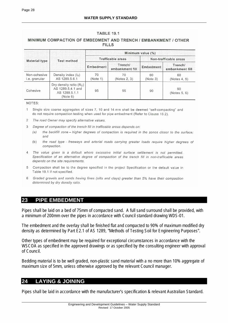
22 COMPACTION
All backfill of excavations shall be compacted in accordance with Section 19.3 of WSCOA. This section can be summarised by Table 19.1 from the WSCOA as follows.
Page 28
WATER SUPPLY STANDARD
Engineering and Development Guidelines – Water Supply Standard
Revised 17 October 2005
23 PIPE EMBEDMENT
Pipes shall be laid on a bed of 75mm of compacted sand. A full sand surround shall be provided, with a minimum of 200mm over the pipes in accordance with Council standard drawing WDS-01.
The embedment and the overlay shall be finished flat and compacted to 90% of maximum modified dry density as determined by Part E2.1 of AS 1289, "Methods of Testing Soil for Engineering Purposes".
Other types of embedment may be required for exceptional circumstances in accordance with the WSCOA as specified in the approved drawings or as specified by the consulting engineer with approval of Council.
Bedding material is to be well graded, non-plastic sand material with a no more than 10% aggregate of maximum size of 5mm, unless otherwise approved by the relevant Council manager.
24 LAYING & JOINING
Pipes shall be laid in accordance with the manufacturer’s specification & relevant Australian Standard.
Page 29
WATER SUPPLY STANDARD
Engineering and Development Guidelines – Water Supply Standard
Revised 17 October 2005
24.1 LAYING AND JOINTING METHOD Pipes shall be laid in accordance with AS 2032 - 1977, "Code of Practice for Installation of U.P.V.C. Pipe Systems" and the manufacturers’ specifications, with flexible joints provided at least every six (6) metres.
Care shall be taken to ensure that the rubber rings and ends of the pipe are clean and lubricated as recommended by the pipe manufacturer, and the ring is correctly seated.
The full length of the pipe barrel shall rest on the sand bed suitably excavated at the socket bell, and the sand surround shall be carefully placed and compacted adjacent to and 200mm over the pipe. The purpose of the cover is to provide a warning of the presence of this pipe. Consequently this material must be different to the surrounding natural material in colour and structure. Should the colour of the sand and the natural material be roughly the same, a 100mm wide green plastic trench marker tape (AS 2700 – 1996) appropriately marked shall be provided directly over the water main on top of the bedding sand (ie 200mm above the pipe). Where the main is not installed in the standard footpath alignment, the trench tape shall contain a tracer wire in it with the ends extending a minimum of 500mm into valve/hydrant pits and ‘tied’ to the fixture such as to enable easy access and visible evidence of its existence. Trench tape shall comply with AS/NZS 2648.1:1995 – Underground marking tape.
When pipe laying is not in progress, the end of the laid pipes shall be sealed to prevent the ingress of foreign material including dust sediment etc.
24.2 THRUST BLOCKS Where bends, junctions, hydrants, valves or end caps are installed, thrust blocks shall be provided in accordance with WSCOA standard drawings WAT-1205 and WAT-1207. Timber Thrust blocks are not acceptable for permanent or temporary works. Where thrust blocks are poured, care shall be taken to ensure that the concrete bears onto the fitting, not the pipe.
24.3 TRENCH STOPS If stops are required, they shall conform to the requirements of standard drawing WAT-1209.
24.4 BULKHEADS Bulkheads are required as per the WSCOA standard drawing WAT-1209.
24.5 CORROSION PROTECTION Corrosion Protection is required on all steel and ductile iron pipes and fittings. In particular, if the pipe or fitting is laid below RL 5.0AHD or in acid sulphate conditions.
Regardless of coating, all fittings shall be plastic sleeved.
24.6 DETECTABLE TAPE Detectable tape is generally not required for domestic mains, on standard alignment unless specified by Council. Any main installed off alignment (requires specific approval of Councils Water Manager), shall be marked by means of detectable tape marker, joined to the nearest hydrant or valve in each direction as per Clause 15.10 of WSCOA. Refer also section 24.1 Laying and Jointing Method.
Page 30
WATER SUPPLY STANDARD
Engineering and Development Guidelines – Water Supply Standard
Revised 17 October 2005
24.7 VALVES AND HYDRANTS The maximum depth between the top of the surface box and the top of the hydrant ‘lug’ shall be 200mm as per standard drawing WAT-1301. Hydrants shall be installed with the bolts on the top of the hydrant directly over the centre of the pipe and be fitted with cast-iron dust covers.
The maximum depth from the top of the surface box to the top of the valve spindle shall be 300mm.
Valve and hydrant surrounds shall generally be single piece recycled plastic. Other margins may be approved on written application, a list of approved products may be available from Council. Valve and hydrant surrounds shall be finished at least 30mm above finished ground level on proposed grass verges or flush with paved surfaces. The ground surrounding the margin shall not be mounded or hollowed to achieve this level. The margin set and C.I. box shall be located directly over the valve or hydrant to allow for easy access of hydrant stand pipes or valve spindles. An expansion joint shall be provided around the margins set into concrete slabs to allow access to the main below for maintenance.
All metal fittings in direct contact with soil shall be plastic sleeved.
24.8 BORED PIPES UNDER ROADS ETC Bored pipes shall be used under existing sealed roads unless otherwise approved by Council.
24.9 AQUEDUCTS The use of aqueducts is not permitted.
24.10 LOCATION MARKERS Location markers shall be installed as per Council standard Drawing WDS-02, and the requirements of Department of Main Roads.
24.11 WATER SERVICES – CSC ONLY Water Service connections are only permitted to be installed following the acceptance of mains from disinfection and pressure testing.
Once installed, water service pipe work is required to remain under pressure at all times.
Each tapping, including connecting pipe work, is to be fully completed once commenced. No tapping shall be left incomplete for any period.
All pipe work shall be left exposed for a minimum of 1 hour following completion of connection.
At this time, a visual and physical check of pipe work is to be made to detect leaks. Once pipe work has been certified leak free, the trench shall be backfilled.
24.11.1 Conduits Water service conduits shall be laid at a minimum 500mm below the finished pavement level and terminated 300mm behind the back of the kerb. Brass service conduit markers shall be installed in the kerb face in line with the end of the conduit. Refer standard drawing WDS-07 for details.
Page 31
WATER SUPPLY STANDARD
Engineering and Development Guidelines – Water Supply Standard
Revised 17 October 2005
The conduit may be required to be inspected by Council after the kerb and channel is poured to ensure the ends are aligned with kerb markers. During this inspection some evidence of the completeness of the conduit is required such as mirroring the line or drawing a wire through the conduit. After this inspection the ends of the conduit shall be fitted with uPVC screw caps and the location of the ends recorded prior to back filling.
Following installation of the service pipe, the conduit is to be sealed with 40-50mm thickness of expansion foam.
24.11.2 Pipes Service pipe is to be installed in accordance with requirements for water mains.
The excavated area within each property is required to be filled with bedding sand to natural surface. The excavation area is to be centrally located around the end of the pipe, with a minimum of 300mm clearance on all sides.
24.11.3 Tapping Band and Ferrule Cock The tapping band is to be installed with the tapping orifice at the top of the main.
The ferrule cock is to be installed vertical, and ‘running with’ the main.
The main is to be tapped at 32mm ND. The tapped plug is to be removed from the main.
The tapping is required to be performed under full mains pressure only, ie ‘hot’ tapped.
Ferrule bend is to be utilised to obtain necessary alignment and angle.
The ferrule cock is to remain in open before enclosing and burial.
24.11.4 Fittings Compression polyethylene fittings are to be installed and tightened to manufacturers’ specifications.
No obvious stress / strain loads to be applied to the pipe, eg no ‘pulled’ pipe.
Prior to end plug being installed, the service line is to be flushed for 30 seconds.
24.11.5 Access Chambers Water service access chambers shall be constructed in accordance with Standard Drawing WDS-06.
The base plate shall be located above the ferrule cock body and be 10mm clear of any of the water fittings.
25 ACCESS CHAMBERS
Access chambers (margins and boxes) for valves and hydrants shall be constructed in accordance with standard drawings WAT-1304 & WAT-1306.
Page 32
WATER SUPPLY STANDARD
Engineering and Development Guidelines – Water Supply Standard
Revised 17 October 2005
26 TOLERANCES ON "AS CONSTRUCTED" WORK
Tolerances on constructed works apply as per Section 21 of the WSCOA.
26.1 HORIZONTAL TOLERANCES 26.1.1 21.2.1 Water mains and in-line structures Do not exceed the following positional tolerances:
(a) Water mains - ±100 mm lateral displacement from the design water main alignment. (b) Appurtenances and structures - lateral displacement as for the water main, and ±200 mm
displacement (from the design position) along the water main axis.
26.1.2 21.2.2 Property services and meters Do not exceed the following positional tolerances:
(a) Property services - ±100 mm displacement along water main axis from the position as specified.
(b) Water meters - ±100 mm displacement from the position as specified
26.2 VERTICAL TOLERANCES 26.2.1 Water mains, property connections and structures Do not deviate the inverts of new water mains, property connections and structures from the specified design level (or interpolated design level) by more than 50 mm higher or lower, providing the depth from final ground surface level to the top of the pipe exceeds the minimum cover stated in Standard Drawings.
Link up to existing water mains or structures at the design levels equal to or greater than the minimum acceptable covers.
26.2.2 Verticality ("plumb") For hydrant risers, access chambers, shrouds and aqueduct piers, apply a tolerance at any point on the pipe or structure as follows:
(a) 30 mm deviation (from vertical) per metre rise in any direction; and (b) limited to a maximum 50 mm cumulative deviation (from vertical) in anyone particular
direction for structures higher than 5 m.
26.3 TOLERANCES ON FINISHED SURFACE STRUCTURES AND FITTINGS For structures and fittings designed flush with the ground / pavement surface or proud of the surface, apply a vertical tolerance on the finished surface levels as follows:
(a) ±5 mm in road reserves, including sealed pavements, road verges, driveways, footways, and pedestrian thoroughfares.
(b) ±5 mm in sealed and trafficable areas within private properties (pedestrian and/or vehicular traffic).
Page 33
WATER SUPPLY STANDARD
Engineering and Development Guidelines – Water Supply Standard
Revised 17 October 2005
(c) +50 mm,-20 mm in private property including garden areas, unsealed areas, non-trafficable areas and areas of occasional traffic (pedestrian and/or vehicular traffic).
27 BACKFILLING
In trafficable areas, the backfill shall be pavement material compacted to 100% Modified Compaction, or cement-stabilised gravel with four percent (4%) cement content.
Minimum cover over mains shall comply with clause 4.3.1 Embedment & Cover of the DESIGN Section of this Standard.
Backfill in footpaths shall be compacted to 95% of maximum modified dry density as determined by Part E2.1 of Australian Standard AS 1289, "Methods of Testing Soil for Engineering Purposes".
Where backfill is actual or potential acid sulphate soil, the disturbed soil shall be neutralised in accordance with any State Planning Policy or Planning Scheme provision for acid sulphate soils. Where practical, impermeable clay trench stops should be constructed at 35m spacing along the trench to prevent the drainage and further oxidation of the acid sulphate soil. These stops should be through to base of the trench substituting for the bedding sand in the immediate area.
28 DISINFECTION
All water mains shall be tested, flushed thoroughly clean and chlorinated before being connected to the existing system.
Test Results must be submitted to Council by a suitably qualified (NATA registered) company before being connected to the existing system.
28.1 FLUSHING & CHLORINATION Pipes which have passed the pressure test shall be flushed clean with mains water and then chlorinated using Calcium Hypochlorite powder. The weight in kilograms of powder used shall be;
Weight(kg)=0.056 x pipe length(m) x [pipe diameter(m)]2 ,
and the chlorinated water shall be retained in the pipe for between at least 36 hours. Sodium hypochlorite may be used in an equivalent concentration - required dosage dependant on chemical used. The Calcium Hypochlorite powder shall be mixed to the correct concentration in a clean water truck filled with mains water. The mains will then be filled from the truck. This ensures a uniform concentration of chlorine ions through out the mains.
Other chlorination agents can be used provided it is certified that the dosage of the agent specified by the Consulting Engineer contains an equivalent concentration of free chlorine ions with in the main.
The pipe shall then be re-flushed with mains water so that the final free chlorine content is less than 1mg/l.
The supervising Consulting engineering will certify that the mains have been disinfected and flushed before connection to the existing water mains.
Page 34
WATER SUPPLY STANDARD
Engineering and Development Guidelines – Water Supply Standard
Revised 17 October 2005
All valve, hydrants and other control structures must be suitably operated during the chlorination process (Section 20 of WSCOA)
29 CONNECTION TO EXISTING MAINS
Connections into existing mains will not be permitted until all upstream mains have been completed, tested, cleaned, chlorinated and flushed.
Gladstone City Council undertakes connections to existing Council water mains at the developers expense.
Calliope Shire Council permits approved persons to undertake connections to existing mains, provided prior written permission is obtained from Council before making the connection. The approval of persons is managed by Water Services Section, with the approval of the connection with the Development Services Section.
Ten (10) working days notice to Council is required prior to connecting into existing mains so that Council’s water customers have adequate notice of the disruption to the service. Any expenses associated with the notices to the public will be borne by the contractor or developer. The disruption of services to numerous people may require advertisement in a local newspaper and/or local radio station.
Under no circumstances will valves on existing live water mains be turned off or on by anybody other than Council staff.
Where a cut in required to a live main, the developer may request Council to cut into the live mains at the commencement of the construction in order to establish the point of connection early in the project. A flanged Tee and valve will be installed into the line which can be easily connected to without major disruption to the consumers. This work would be at the expense of the developer, however it may minimise delays later on in the project.
30 RESTORATION & CLEAN UP
If water mains must be laid through existing developments, any areas which are affected by the works shall be restored to a condition equivalent to that which existed prior to the work starting. Restoration shall be carried out as soon as the trench has been backfilled and the new main has been tested satisfactorily. All rubbish and spoil shall be removed and the area left in a neat, tidy and near original condition. Refer Section 20.2 Excavation Across Improved Surfaces for further requirements for restoration.
30.1 STORMWATER QUALITY The excavated and disturbed area resulting from the construction of water mains shall stabilised to minimise wind and water erosion of the restored area including any measures required by Council to achieve the objectives of Council’s Stormwater Quality Objectives. Measures required by Council may include turfing, silt fences, etc.
These measures will be required to be maintained for the duration of the maintenance period.
Page 35
WATER SUPPLY STANDARD
Engineering and Development Guidelines – Water Supply Standard
Revised 17 October 2005
30.2 EROSION PROTECTION In all areas of new installation, reinstated trenches shall be adequately protected from erosion immediately upon the reinstatement completion. This protection as a minimum shall be:
Rural areas silt fence or hay bales
Urban Areas pre-grown turf
These measures will be required to be maintained for the duration of the maintenance period.
30.3 HYDRANT & VALVE MAINTENANCE In all areas of new installation, hydrants and valves shall be adequately protected from the effects of erosion immediately upon the reinstatement completion. This protection as a minimum shall ensure full location and access abilities at all times. That is the hydrant or valve must be clearly visible at the surface and not buried of covered. Any situation which results in a hydrant or valve not being accessible will be required to be rectified within 12 hours of notification, or Council may carry out the work and deduct this from any bonds held.
31 WORKS AS CONSTRUCTED INFORMATION
Works as constructed water reticulation information shall be prepared to comply with Council's standard Specification for As-Constructed information, contained in Council’s “Engineering and Development Guidelines”.
Preliminary as-constructed information showing the location of all water mains and service conduits is required prior to endorsing of the plan of reconfiguration.
Final as-constructed information showing all water reticulation detail is required prior to Council accepting the works on-maintenance.
32 PROCEDURAL REQUIREMENTS
The following sections outline the procedural requirements of the design and construction of water reticulation works.
32.1 DESIGN CHECK LISTS Appendix A contains a checklist which shall be completed and submitted with the design drawings and specifications. Boxes should be ticked as items are checked.
All checklists must be signed off by Registered Professional Engineer, Queensland (Civil) in order to be accepted by Council.
32.2 INSPECTION AUDITS At various stages of works during the construction period, a representative of Council shall be invited to carry out audit inspections.
Page 36
WATER SUPPLY STANDARD
Engineering and Development Guidelines – Water Supply Standard
Revised 17 October 2005
Without limitation, inspections shall be at the “hold points” detailed below, and construction shall not proceed beyond a "hold point" without approval.
Inspections will only be carried with the Supervising Engineer during normal office working hours with a minimum of 24 business hours notice.
32.3 INSPECTIONS Inspections for water reticulation works are required in accordance with the following requirements. Hold point forms outline the minimum works to be completed before the inspection is to take place.
Hold point forms will generally be issued by each Council after the works are approved by Council. Hold point forms outline the pre-requisites to be completed before a particular inspection takes place. When the Supervising Consulting Engineers have inspected the work and is satisfied that the works are ready for the next stage to commence, they shall sign and fax the completed hold point form to Council and arrange an inspection.
Inspections shall be carried out at the stages as outlined in the following paragraphs.
A pre-start meeting must be carried out before works commence to familiarise contractors, engineers and Council representatives with the procedures for carrying out the works and to sort out any administrative matters necessary such as construction water, site safety, inspection procedures etc.
The supervising consulting engineer shall instruct the persons constructing the works to arrange the inspection of the works by the supervising engineer and a Council inspector at the stages listed below.
At least forty eight hours notice of the inspection is required. Council may decline the inspection however the supervising engineer must attend every inspection and certify the works in accordance with section 32.4 Certification by Supervising Consulting Engineer of this standard.
The works shall be inspected at the following critical stages of construction:
1. Sand surround and Maintenance holes prior to back filling,
2. Pressure testing,
3. On-maintenance, and
4. Off-maintenance.
At all of the above inspections, the location of the property boundary shall be clearly pegged to ensure correct alignment and locations. The supervising consulting engineer shall inspect the works as per proforma audit sheets, with the relevant Council officer also invited to attend each inspection
Page 37
WATER SUPPLY STANDARD
Engineering and Development Guidelines – Water Supply Standard
Revised 17 October 2005
32.4 CERTIFICATION BY SUPERVISING CONSULTING ENGINEER The supervising Consulting Engineer shall certify that the works have been inspected and carried out in accordance with the requirements of this standard. The Supervising Engineer must be a Registered Professional Engineer of Queensland or have current NPER3 registration. When design and works are certified, the following shall be provided as a part of a properly made certification:
a) Company name, address, & contact details b) Person’s name, position in company, qualifications, c) Professional registration number, body name, & signature. d) Details of what is Certified, which may include the whole or part of a project (hence further
specifics required ), and date of installation e) Relevant standards and documents to which the product or installation complies. f) Quality assurance system in place, and date of QM manual used. g) Maintenance procedures required for products certified (optional)
The standard pro-forma supplied in Appendix A shall be used for each inspection, as well as any other documentation volunteered by the consultant.
Certification of each inspection must be submitted to Council within two days of carrying out the inspection. The subdivision will not be accepted on to the maintenance period if these certificates are not submitted to Council in accordance with the above requirements.
32.5 MAINTENANCE PERIOD The work shall be maintained by the contractor/developer for a period of 12 months from the date it is accepted on-maintenance by Council. During the maintenance period, the developer shall make good any defects which appear in the work. Rectification of defects shall be completed within 7 days of being notified by Council. Should the necessary repairs not be carried out within the specified time, Council may carry out the work and deduct the cost from the Maintenance Bond lodged by the developer.
The commencement of the maintenance period may be delayed by the following not occurring within 4 weeks of the acceptance of the works for the maintenance period:
• Rectification or completion of outstanding requirements from the works acceptance.
• The plan of survey not endorsed by Council.
• Final "as constructed" plans of the sewerage infrastructure are submitted to Council not being received within 4 weeks of on maintenance inspection.
Council may extend the maintenance period if;
• The works have not been performed satisfactorily.
• Substantial use of the infrastructure or development of the adjacent land has not occurred.
Page 38
WATER SUPPLY STANDARD
Engineering and Development Guidelines – Water Supply Standard
Revised 17 October 2005
• Certified as-constructed plans of all infrastructure including power and telephone have not been accepted by Council, or
• The Plan of Survey over the subject land has not been registered at the expiration of the specified maintenance period.
The extension period may be for a period of up to 12 months after the resolution of the above issues.
33 WATER FOR CONSTRUCTION
Water is essential for the construction of a subdivision, in particular road and earth works. Where alternate sources of water are available such as reclaimed water ground water etc, the alternate source shall be utilised. Alternate sources of water are available at Calliope, Boyne Island and Tannum Sands.
All water obtained from Council’s reticulation system shall only be obtained through registered metered components complying with the section on “BACK FLOW PREVENTION” and Registered Standpipes. The arrangements for obtaining water from water mains must be made with the respective Council.
Contractors may request to supply their own metered standpipes, subject to registration of the standpipe with Council. These stand pipes shall be inspected by Council on installation prior to use by the contractor. The meter on the stand pipe shall be read monthly and calibrated on installation and at 6 monthly intervals. Damaged meters shall be replaced immediately, and an estimate of water consumption will be made by Council. Non-registered standpipes will be removed by Council and the matter fully investigated. Certificates of meter calibration are required before Council accepts the use of private stand pipes. The developer remains liable for all water usage through the devices.
The contractor is liable for payment of all fees associated with the use of the devices and the water consumption.
This use of construction water is subject to any water restrictions in place at the time.
The location of accessing Council’s mains for obtaining construction water is specified only by Council’s Water Services Section, and written approval of locations must be sought prior to commencement of works.
33.1 BACK FLOW PREVENTION Council enforces the requirements of AS/NZS 3500 Plumbing and Drainage for back flow prevention in relation to town water supplies. Consequently back flow prevention devices shall be provided in all situations.
With regards to filling water trucks directly from the mains/hydrants, the simplest acceptable method of back flow prevention is the air gap, where there is a gap of twice the diameter of the filler pipe between the connecting hose and the top of the tank. The second method is a reduced pressure zone (RPZ) device and two valves installed on the line between the truck and the source of water. All RPZ devices must be registered and maintained in accordance with the relevant Australian standards. These two devices are illustrated in the diagrams following.
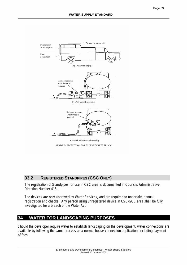
Page 39
WATER SUPPLY STANDARD
Engineering and Development Guidelines – Water Supply Standard
Revised 17 October 2005
Hose Connection
Permanently attached pipes
A) Truck with air gap.
Air gap - 2 x pipe I.D.
Reduced pressure zone device as required
B) With portable assembly
Reduced pressure zone device as required
C) Truck with mounted assembly
MINIMUM PROTECTION FOR FILLING TANKER TRUCKS
33.2 REGISTERED STANDPIPES (CSC ONLY) The registration of Standpipes for use in CSC area is documented in Councils Administrative Direction Number 418.
The devices are only approved by Water Services, and are required to undertake annual registration and checks. Any person using unregistered device in CSC/GCC area shall be fully investigated for a breach of the Water Act.
34 WATER FOR LANDSCAPING PURPOSES
Should the developer require water to establish landscaping on the development, water connections are available by following the same process as a normal house connection application, including payment of fees.
Page 40
WATER SUPPLY STANDARD
Engineering and Development Guidelines – Water Supply Standard
Revised 17 October 2005
Council will provide the developer with a standard water connection including water meter. The developer will be levied the access fee and water consumption fees by Council which will be as listed in Council’s annual rates and charges booklet listed under “Water Connection Fees”.
The water service will only be installed on an actual lot in compliance with Councils operating plans for water services.
Following installation the meter will be read and billed as per Council’s normal billing regime. The developer remains liable for water usage through such connection, until the sale of the property on which the water meter is located. Once the property is sold, the developer is not entitled access to the water service.
The use of broad range (across more than one property frontage) in-ground irrigation is not permitted.
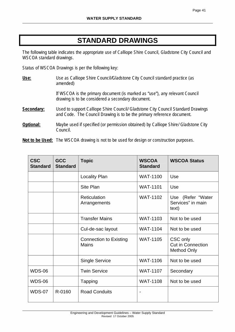
Page 41
WATER SUPPLY STANDARD
Engineering and Development Guidelines – Water Supply Standard
Revised 17 October 2005
STANDARD DRAWINGS The following table indicates the appropriate use of Calliope Shire Council, Gladstone City Council and WSCOA standard drawings.
Status of WSCOA Drawings is per the following key:
Use: Use as Calliope Shire Council/Gladstone City Council standard practice (as amended)
If WSCOA is the primary document (is marked as “use”), any relevant Council drawing is to be considered a secondary document.
Secondary: Used to support Calliope Shire Council/ Gladstone City Council Standard Drawings and Code. The Council Drawing is to be the primary reference document.
Optional: Maybe used if specified (or permission obtained) by Calliope Shire/ Gladstone City Council.
Not to be Used: The WSCOA drawing is not to be used for design or construction purposes.
CSC Standard
GCC Standard
Topic WSCOA Standard
WSCOA Status
Locality Plan WAT-1100 Use
Site Plan WAT-1101 Use
Reticulation Arrangements
WAT-1102 Use (Refer “Water Services” in main text)
Transfer Mains WAT-1103 Not to be used
Cul-de-sac layout WAT-1104 Not to be used
Connection to Existing Mains
WAT-1105 CSC only Cut in Connection Method Only
Single Service WAT-1106 Not to be used
WDS-06 Twin Service WAT-1107 Secondary
WDS-06 Tapping WAT-1108 Not to be used
WDS-07
R-0160 Road Conduits -
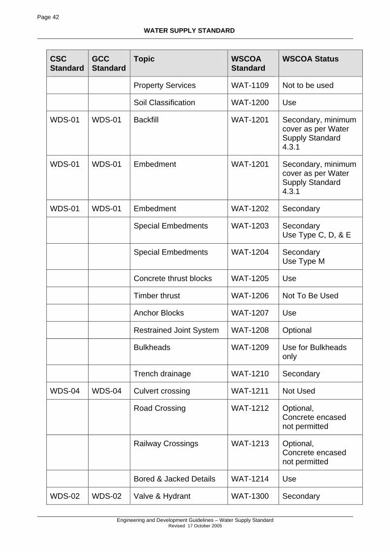
Page 42
WATER SUPPLY STANDARD
Engineering and Development Guidelines – Water Supply Standard
Revised 17 October 2005
CSC Standard
GCC Standard
Topic WSCOA Standard
WSCOA Status
Property Services WAT-1109 Not to be used
Soil Classification WAT-1200 Use
WDS-01 WDS-01 Backfill WAT-1201 Secondary, minimum cover as per Water Supply Standard 4.3.1
WDS-01 WDS-01 Embedment WAT-1201 Secondary, minimum cover as per Water Supply Standard 4.3.1
WDS-01 WDS-01 Embedment WAT-1202 Secondary
Special Embedments WAT-1203 Secondary Use Type C, D, & E
Special Embedments WAT-1204 Secondary Use Type M
Concrete thrust blocks WAT-1205 Use
Timber thrust WAT-1206 Not To Be Used
Anchor Blocks WAT-1207 Use
Restrained Joint System WAT-1208 Optional
Bulkheads WAT-1209 Use for Bulkheads only
Trench drainage WAT-1210 Secondary
WDS-04 WDS-04 Culvert crossing WAT-1211 Not Used
Road Crossing WAT-1212 Optional, Concrete encased not permitted
Railway Crossings WAT-1213 Optional, Concrete encased not permitted
Bored & Jacked Details WAT-1214 Use
WDS-02 WDS-02 Valve & Hydrant WAT-1300 Secondary
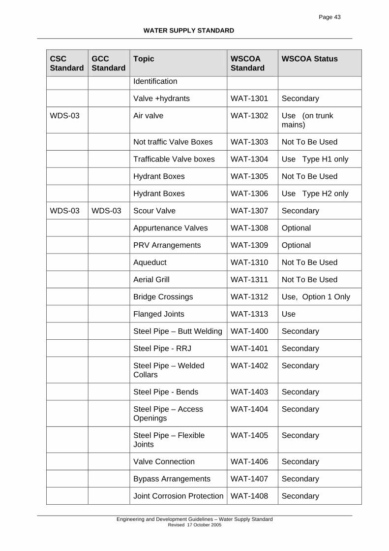
Page 43
WATER SUPPLY STANDARD
Engineering and Development Guidelines – Water Supply Standard
Revised 17 October 2005
CSC Standard
GCC Standard
Topic WSCOA Standard
WSCOA Status
Identification
Valve +hydrants WAT-1301 Secondary
WDS-03 Air valve WAT-1302 Use (on trunk mains)
Not traffic Valve Boxes WAT-1303 Not To Be Used
Trafficable Valve boxes WAT-1304 Use Type H1 only
Hydrant Boxes WAT-1305 Not To Be Used
Hydrant Boxes WAT-1306 Use Type H2 only
WDS-03 WDS-03 Scour Valve WAT-1307 Secondary
Appurtenance Valves WAT-1308 Optional
PRV Arrangements WAT-1309 Optional
Aqueduct WAT-1310 Not To Be Used
Aerial Grill WAT-1311 Not To Be Used
Bridge Crossings WAT-1312 Use, Option 1 Only
Flanged Joints WAT-1313 Use
Steel Pipe – Butt Welding WAT-1400 Secondary
Steel Pipe - RRJ WAT-1401 Secondary
Steel Pipe – Welded Collars
WAT-1402 Secondary
Steel Pipe - Bends WAT-1403 Secondary
Steel Pipe – Access Openings
WAT-1404 Secondary
Steel Pipe – Flexible Joints
WAT-1405 Secondary
Valve Connection WAT-1406 Secondary
Bypass Arrangements WAT-1407 Secondary
Joint Corrosion Protection WAT-1408 Secondary
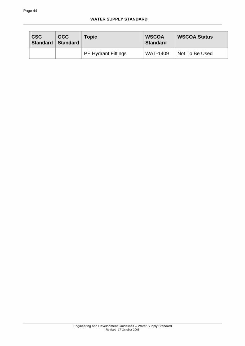
Page 44
WATER SUPPLY STANDARD
Engineering and Development Guidelines – Water Supply Standard
Revised 17 October 2005
CSC Standard
GCC Standard
Topic WSCOA Standard
WSCOA Status
PE Hydrant Fittings WAT-1409 Not To Be Used
Page 45
WATER SUPPLY STANDARD
Engineering and Development Guidelines – Water Supply Standard
Revised 17 October 2005
APPENDIX A – STANDARD DRAWINGS
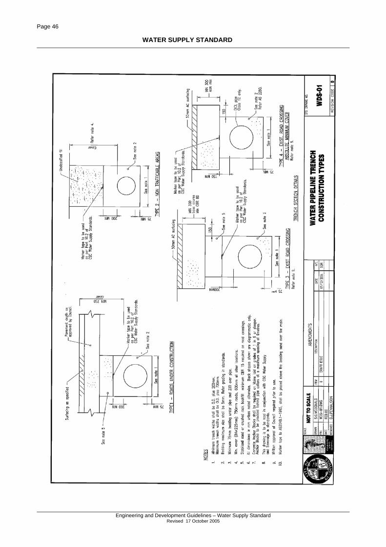
Page 46
WATER SUPPLY STANDARD
Engineering and Development Guidelines – Water Supply Standard
Revised 17 October 2005
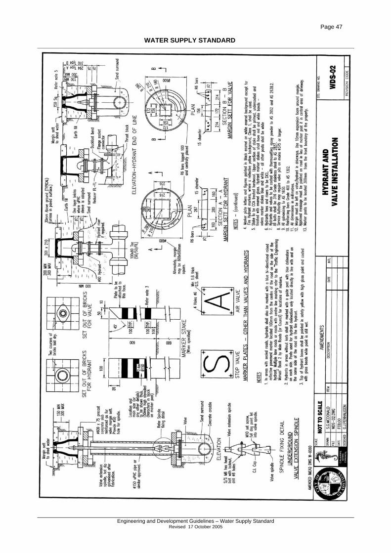
Page 47
WATER SUPPLY STANDARD
Engineering and Development Guidelines – Water Supply Standard
Revised 17 October 2005
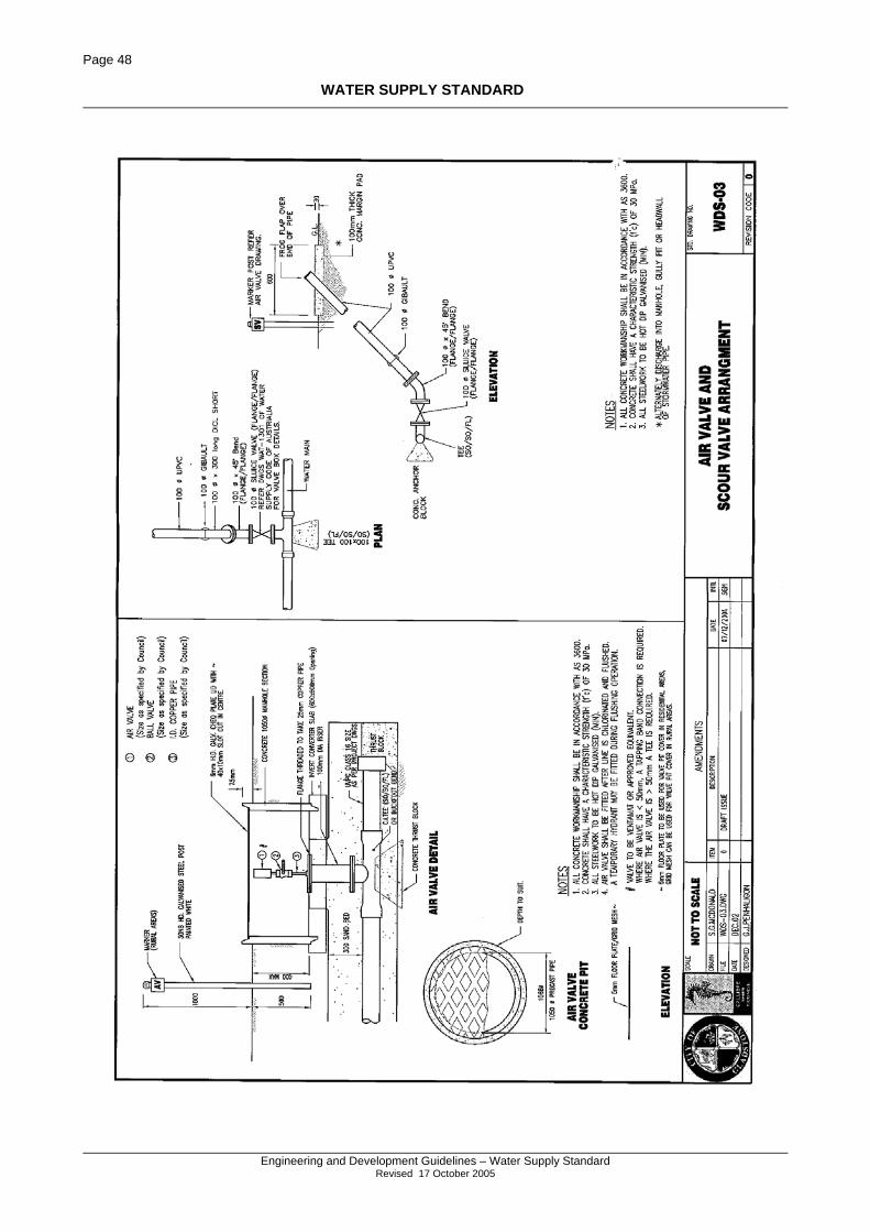
Page 48
WATER SUPPLY STANDARD
Engineering and Development Guidelines – Water Supply Standard
Revised 17 October 2005
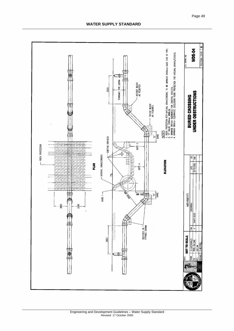
Page 49
WATER SUPPLY STANDARD
Engineering and Development Guidelines – Water Supply Standard
Revised 17 October 2005
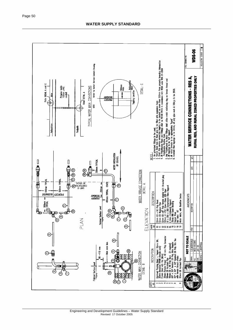
Page 50
WATER SUPPLY STANDARD
Engineering and Development Guidelines – Water Supply Standard
Revised 17 October 2005
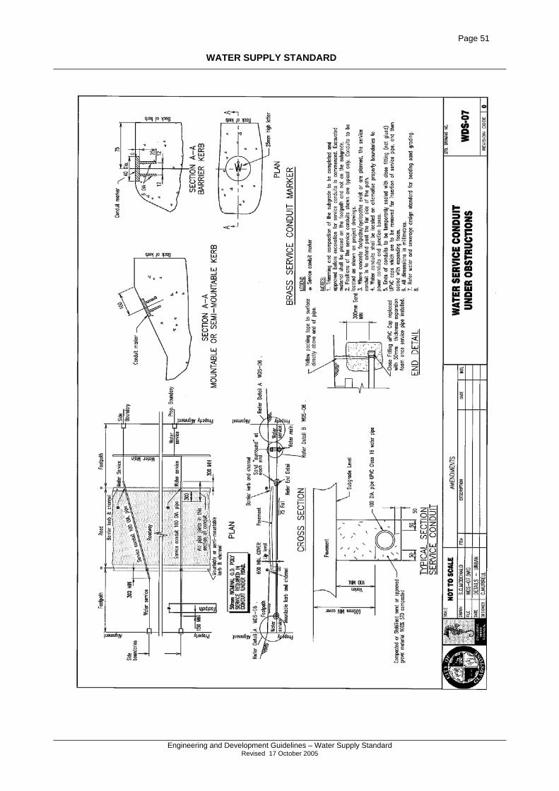
Page 51
WATER SUPPLY STANDARD
Engineering and Development Guidelines – Water Supply Standard
Revised 17 October 2005
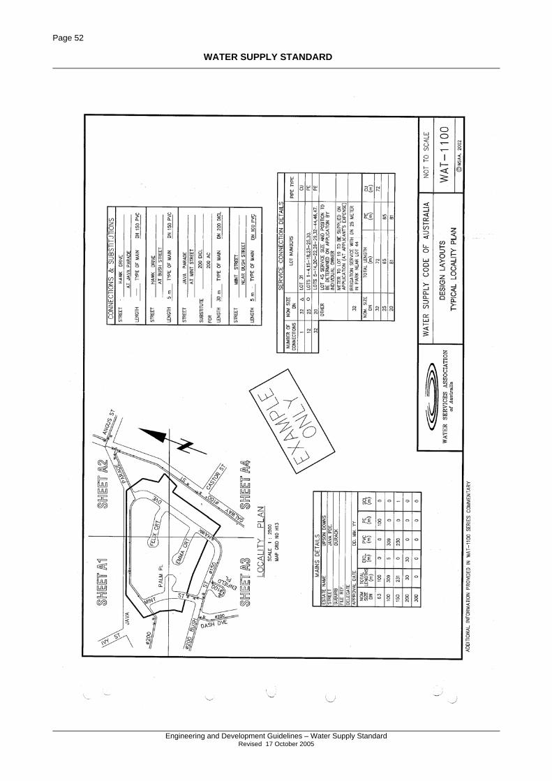
Page 52
WATER SUPPLY STANDARD
Engineering and Development Guidelines – Water Supply Standard
Revised 17 October 2005
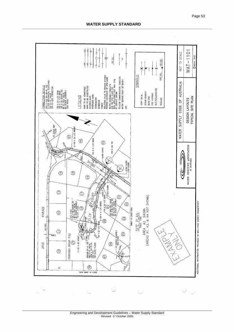
Page 53
WATER SUPPLY STANDARD
Engineering and Development Guidelines – Water Supply Standard
Revised 17 October 2005
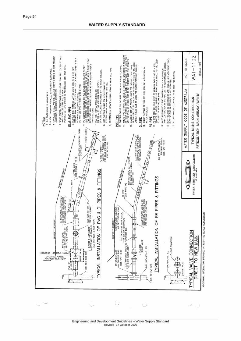
Page 54
WATER SUPPLY STANDARD
Engineering and Development Guidelines – Water Supply Standard
Revised 17 October 2005
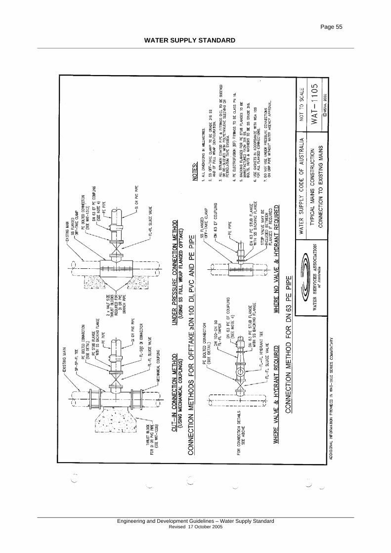
Page 55
WATER SUPPLY STANDARD
Engineering and Development Guidelines – Water Supply Standard
Revised 17 October 2005
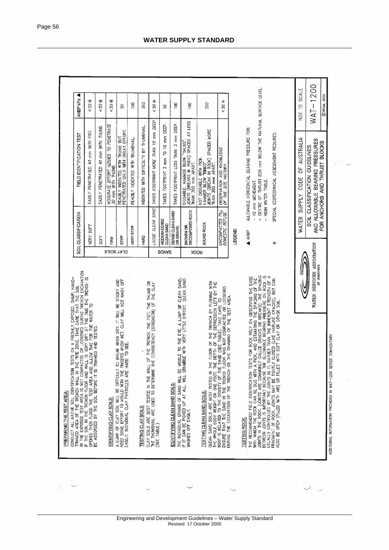
Page 56
WATER SUPPLY STANDARD
Engineering and Development Guidelines – Water Supply Standard
Revised 17 October 2005
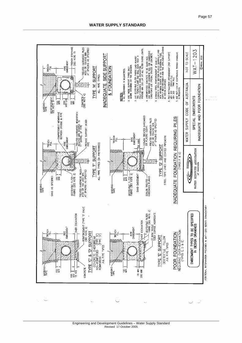
Page 57
WATER SUPPLY STANDARD
Engineering and Development Guidelines – Water Supply Standard
Revised 17 October 2005
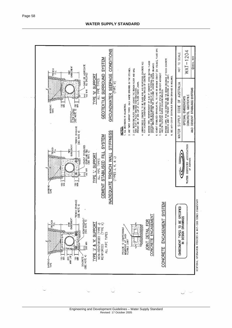
Page 58
WATER SUPPLY STANDARD
Engineering and Development Guidelines – Water Supply Standard
Revised 17 October 2005
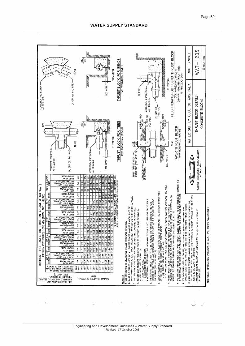
Page 59
WATER SUPPLY STANDARD
Engineering and Development Guidelines – Water Supply Standard
Revised 17 October 2005
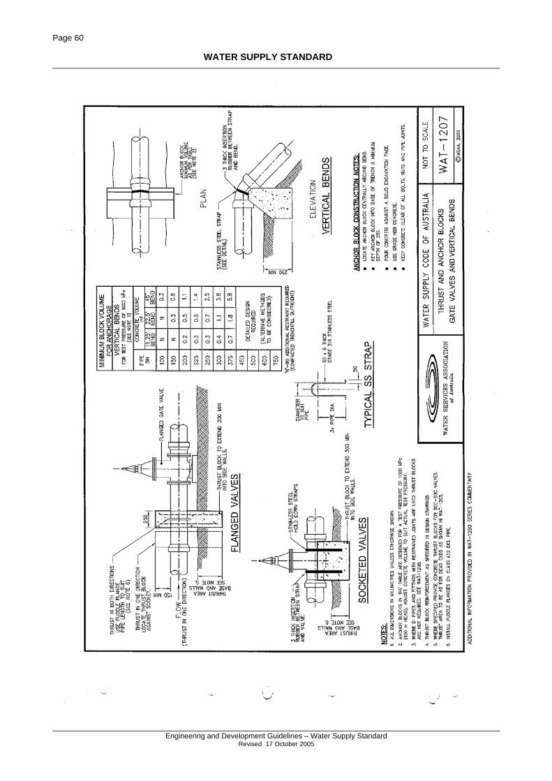
Page 60
WATER SUPPLY STANDARD
Engineering and Development Guidelines – Water Supply Standard
Revised 17 October 2005
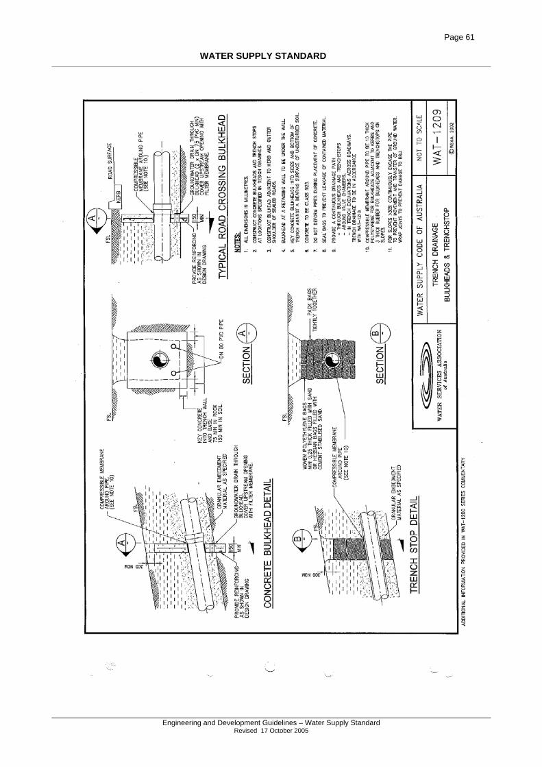
Page 61
WATER SUPPLY STANDARD
Engineering and Development Guidelines – Water Supply Standard
Revised 17 October 2005
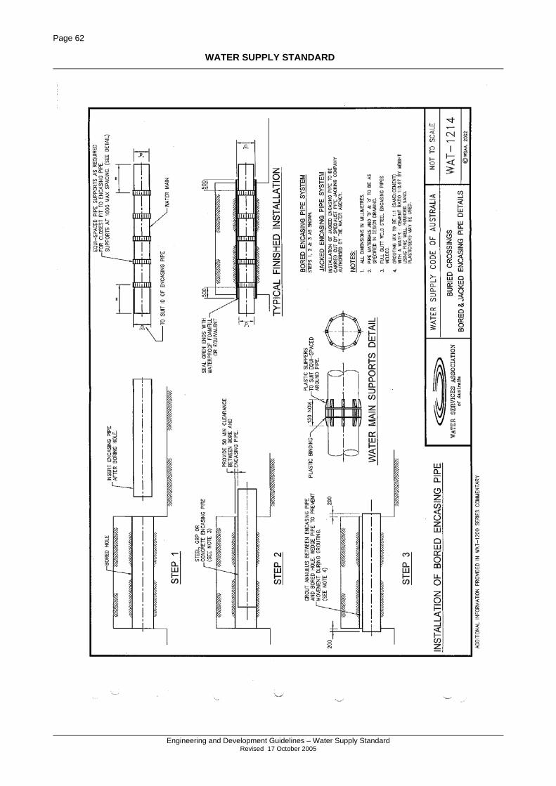
Page 62
WATER SUPPLY STANDARD
Engineering and Development Guidelines – Water Supply Standard
Revised 17 October 2005
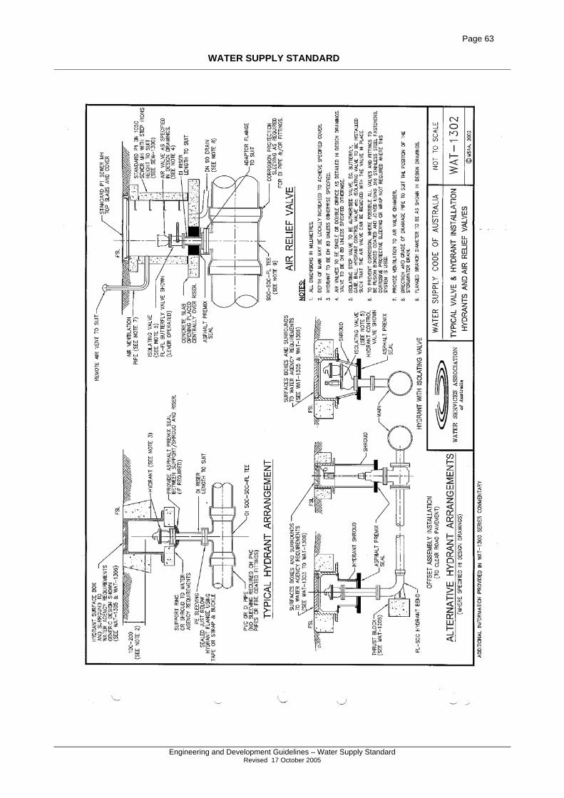
Page 63
WATER SUPPLY STANDARD
Engineering and Development Guidelines – Water Supply Standard
Revised 17 October 2005
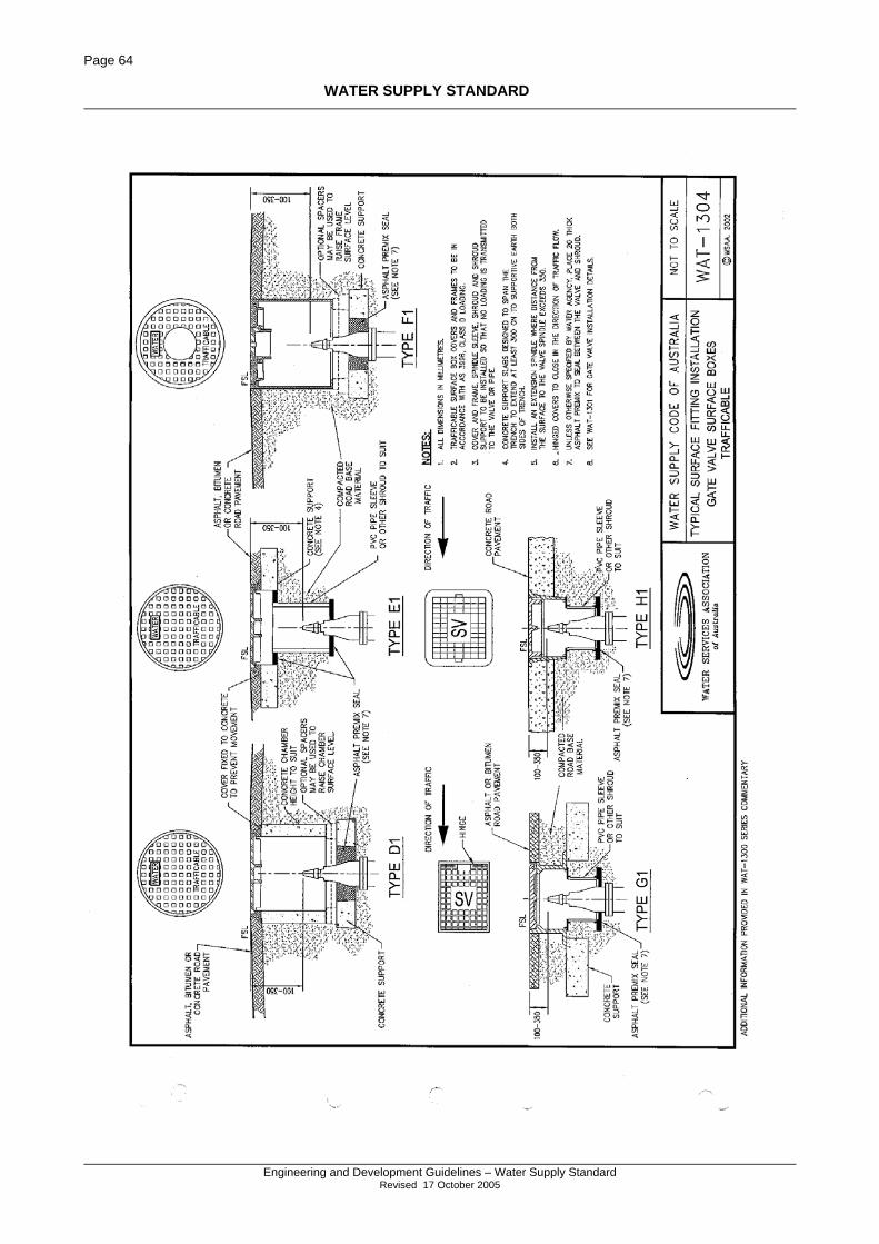
Page 64
WATER SUPPLY STANDARD
Engineering and Development Guidelines – Water Supply Standard
Revised 17 October 2005
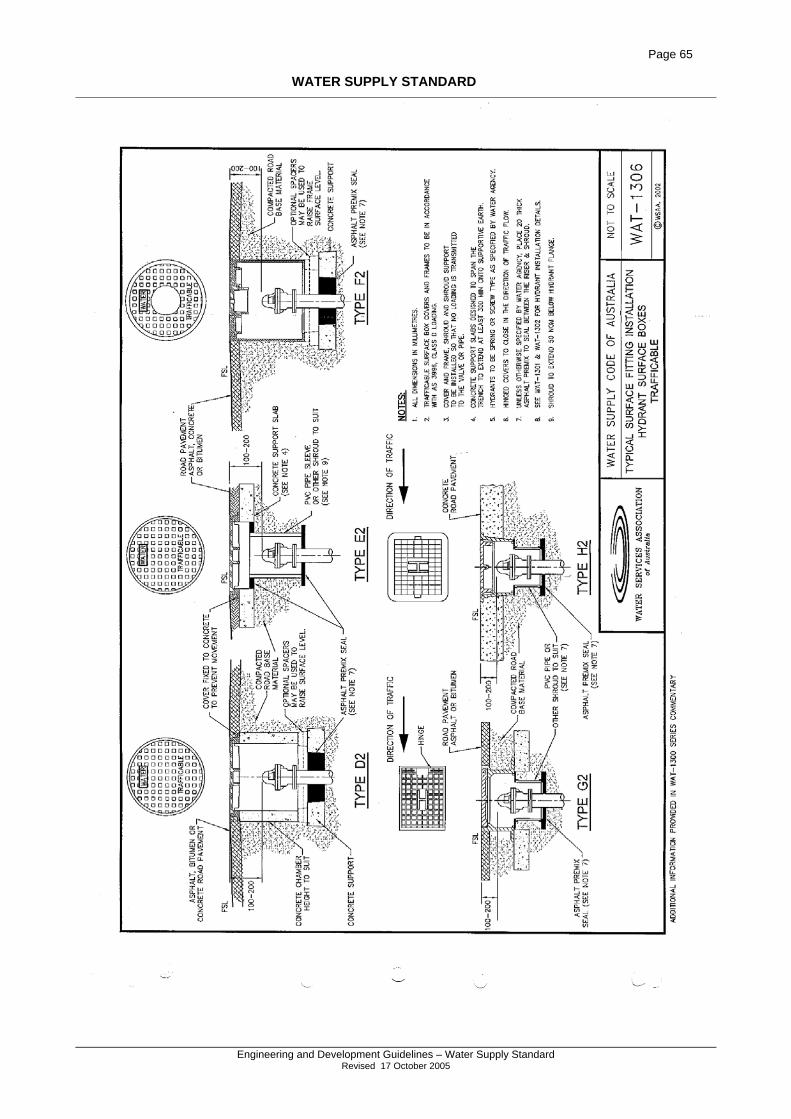
Page 65
WATER SUPPLY STANDARD
Engineering and Development Guidelines – Water Supply Standard
Revised 17 October 2005
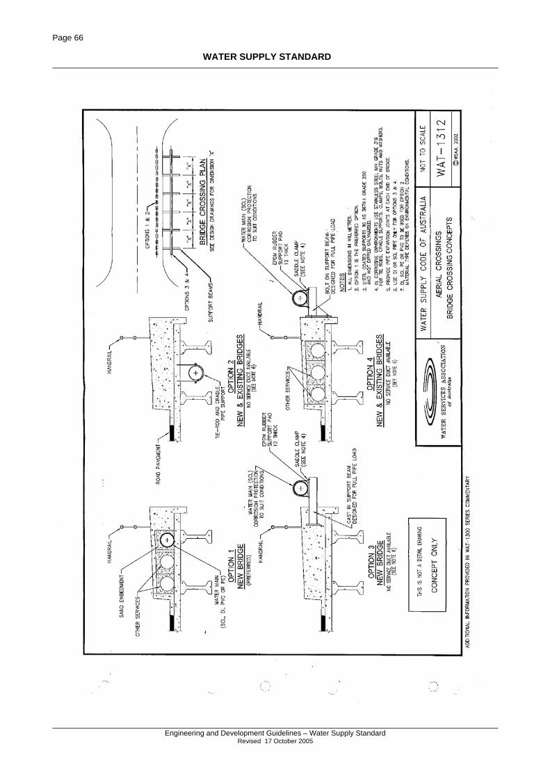
Page 66
WATER SUPPLY STANDARD
Engineering and Development Guidelines – Water Supply Standard
Revised 17 October 2005
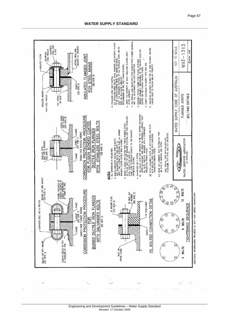
Page 67
WATER SUPPLY STANDARD
Engineering and Development Guidelines – Water Supply Standard
Revised 17 October 2005
Page 68
WATER SUPPLY STANDARD
Engineering and Development Guidelines – Water Supply Standard
Revised 17 October 2005
Page 69
WATER SUPPLY STANDARD
Engineering and Development Guidelines – Water Supply Standard
Revised 17 October 2005
INDEX
A
ACCESS CHAMBERS ........................................... 35 ACID SULPHATE SOILS ............................................... 22 Air Valves.................................................................. 15 Alignment .................................................................... 8 Aqueducts .................................................................. 33 AS CONSTRUCTED INFORMATION......................... 19, 38
B
Back Flow Prevention ............................................... 42 BACKFILLING STANDARDS ............................. 36 BEDDING .............................................................. 11, 31 Bedding Material ....................................................... 23 BENDS AND CURVES..................................................... 9 BULKHEADS ......................................................... 12, 32
C
Certification ............................................................... 40 Clearances.................................................................. 13 COMPACTION ....................................................... 30 CONCRETE.................................................................. 23 Constant Flow Water ................................................... 6 CONSTRUCTION - WATER FOR ROADWORKS
.............................................................................. 41 COVER........................................................................ 11 Cul-de-sacs ................................................................ 10
D
Design Check Lists.................................................... 39 Detectable Tape ......................................................... 33 DISINFECTION ...................................................... 36 Drawing Requirements .............................................. 18 DUCTILE IRON
FITTINGS................................................................ 21
E
Erosion Protection ..................................................... 38 Excavation - Sealed Roads .................................. 29, 38
F
Fill Material ............................................................... 23 FILLING .................................................................. 30 FIRE HYDRANTS - DESIGN .......................................... 14 Fittings....................................................................... 21 Flushing & Chlorination............................................ 37
G
GIBAULT - SPECIFICATION.......................................... 21
H
HYDRANT DUCKS FOOT BEND ................................... 14 HYDRANTS
INSTALLATION ....................................................... 33 LOCATION.............................................................. 14 MATERIAL SPECIFICATION..................................... 21
I
INSPECTION AND TEST PLANS .................................... 28 INSPECTIONS.......................................................... 39 Inspections - Council ................................................. 39 INTERSECTIONS........................................................... 10
J
JOINT DEFLECTIONS ...................................................... 9
L
LANDSCAPING - WATER FOR .......................... 44 LAYING & JOINING ............................................. 32 Layout And Alignment ................................................ 8 Location Markers....................................................... 33
M
Maintenance Erosion Protection................................................. 38 Hydrant ................................................................. 38 Stormwater Quality ............................................... 38 Valve ..................................................................... 38
Maintenance Periods.................................................. 41 MARGINS - VALVE AND HYDRANT............................. 33 MARKER POSTS .......................................................... 15 Marker Posts - Hydrant And Valve ........................... 23 MARKER TAPE............................................................ 32 Markers Posts............................................................. 33 Metering pits .............................................................. 18
N
NICKEL ANTI-SEIZE GREASE ...................................... 21
P
PIPE CURVATURE.......................................................... 9 PIPES - MATERIALS............................................. 20 Plans
Sign Off................................................................... 6 PREFERRED PIPE SIZES ................................................. 8 Pressure Zones ........................................................... 18 PUMPING STATIONS .................................................... 12
Q
QUALIFICATIONS DESIGN.................................................................. 6
R
Reservoirs .................................................................. 12
S
Scours ........................................................................ 15 SERVICE DESIGN......................................................... 16 Service Storage .......................................................... 12 SERVICE VALVES........................................................ 13 SERVICES - EXISTING.................................................. 29 SHARED TRENCHES ...................................................... 9 SLEEVING ................................................................... 32
Page 70
WATER SUPPLY STANDARD
Engineering and Development Guidelines – Water Supply Standard
Revised 17 October 2005
STAND PIPES......................................................... 41, 44 LOCATION.............................................................. 42 Registration........................................................... 44
STANDARDS 1289 ................................................................ 31, 36 1379 ...................................................................... 23 1477 ...................................................................... 20 1594 ...................................................................... 20 2032 ...................................................................... 32 2280 ................................................................ 20, 21 2518 ................................................................ 20, 21 2638.2 ................................................................... 21 2648.1 ................................................................... 32 2700 ...................................................................... 32 3500 ...................................................................... 42 3680 ...................................................................... 20 4130 ................................................................ 20, 22 4441 ...................................................................... 20 4765 ...................................................................... 20
Stormwater Quality.................................................... 38 SURROUNDS- VALVE AND HYDRANT......................... 33
T
TAPPING BANDS ................................................... 16, 17 Testing ....................................................................... 28 THRUST BLOCKS
CONSTRUCTION ..................................................... 32 THRUST BLOCKS ........................................................ 12 TOLERANCES........................................................ 35 Trench Stops.............................................................. 32
TRENCHSTOPS............................................................. 12
V
VALVES ...................................................................... 15 SPECIFICATION....................................................... 21 WATER .................................................................. 13
W
Water Agency .............................................................. 5 WATER CONNECTIONS
NON-RESIDENTIAL ................................................. 18 WATER CONNECTIONS - COMMERCIAL....................... 16 WATER FOR CONSTRUCTION ......................... 41 WATER FOR LANDSCAPING............................. 44 Water Quality............................................................. 13 Water Service
Calliope Shire........................................................ 17 FITTINGS ................................................................ 17 Gladstone City....................................................... 16 Installation............................................................. 33 Pipe ....................................................................... 17
Water Service Conduit Markers ................................ 34 WATER SERVICE CONDUITS ....................................... 22
INSTALLATION ....................................................... 34 WORKS AS CONSTRUCTED ......................................... 38
Z
Zone Meters ............................................................... 18
Page 71
WATER SUPPLY STANDARD
Engineering and Development Guidelines – Water Supply Standard
Revised 17 October 2005
DOCUMENT INFORMATION
File name: draft WATER Supply Standard 2004 4.doc File Location: Author: Public Release Information :
Status Release Document Name Date Draft Water Supply & Sewerage
Guidelines Wat& Sew3.doc 16/1/96
Draft Water Design Standard 2001 WATER DESIGN STD 2001.doc
Approved Water Design Standard 2001 WATER DESIGN STD 2001.doc
January 2003
Draft Water Supply Standard 2005 JULY 2005 Scheme Notification
Water Supply Standard 2005 WATER DESIGN STD 2005 5.doc
October 2005
Related files: Check list for design purposes: Nil Blank pages required for double sided printing. Watch for loss of subscripts and superscripts with reformating.