Embed Size (px)
Citation preview
CADANGAN PEMBANGUNAN PANGSAPURI 19 TINGKAT (280 UNIT) YANG MENGANDUNGI :-
1. 3 TINGKAT SEMI BASEMENT TEMPAT LETAK
KERETA DI TINGKAT BAWAH TANAH 1, 2 DAN 3 2. BILIK MEKANIKAL DAN SURAU DI TINGKAT BAWAH
TANAH 1 3. 1 TINGKAT PODIUM KEMUDAHAN(PEJABAT
PENGURUSAN, TADIKA, 2 UNIT RUANG PERNIAGAAN, GIMNASIUM, KAFETERIA, PASAR MINI, DEWAN SERBAGUNA, KOLAM RENANG DAN BILIK MEKANIKAL) DI TINGKAT BAWAH
4. BLOK A-18 TINGKAT PANGSAPURI (140 UNIT) DI TINGKAT 1-18
5. BLOK B-18 TINGKAT PANGSAPURI (140 UNIT) DI TINGKAT 1-18
DI ATAS LOT 1013 (PT 7026), JALAN PIPIT, BANDAR PUCHONG
JAYA, PUCHONG, MUKIM PETALING, DAERAH PETALING, SELANGOR DARUL EHSAN UNTUK TETUAN DYNAMIC
MANAGEMENT SDN BHD.
WATER SUPPLY CALCULATION
Jurutera Perunding MajuJurutera Perunding MajuJurutera Perunding MajuJurutera Perunding Maju (Company No. 586937-D)
CONSULTING CIVIL & STRUCTURAL ENGINEERS
7A, 1st Floor, Jalan 20/14, Paramount Garden, 46300 Petaling Jaya, Selangor.
Tel: 03-78748741, 78748082, 78741166 Fax No: 03-78760734
email: [email protected]
APR 2016
Table of Contents 1. Introduction 1
2. Water Demand 2
3. Design Criteria for Water Reticulation Mains 3
4. Sample Calculation of Pipe Design 6
Appendix
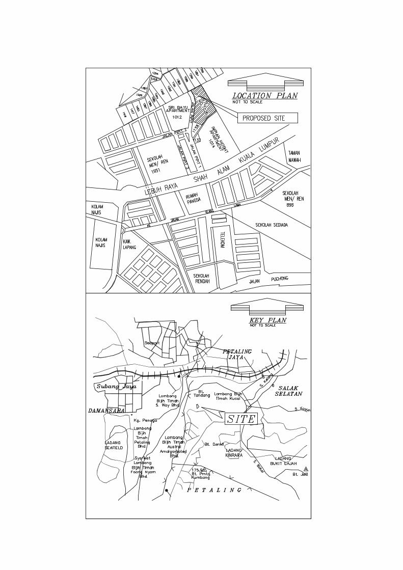
Appendix A Key Plan and Location Plan
Appendix B Approval Letters from SPAN
1.0 INTRODUCTION The design of this water reticulation is for the proposed development of
residential for housing development which is located on Lot 1013, PT. No. 7026,
Bandar Puchong Jaya, Mukim Petaling, Daerah Petaling, Selangor Darul Ehsan.
This development consists of 280 units apartment, management office,
kindergarten, business area and other facilities. The developer for this project is
Messrs. Dynamic Management Sdn Bhd.
The proposed site is an approximately 18, 165m2 which is located near to Jalan
Pipit. The site is bounded by Sri Bayu Apartment on the western and the southern
boundary is bounded by Impian Height Apartment.
This report is prepared for the approval of Syarikat Bekalan Air Selangor
(SYABAS) on the analysis and design of water supply system by using EPANET.
2.0 PROJECT DESCRIPTION Messrs. Dynamic Management Sdn Bhd is intended to develop the site into
residential area. The proposed development is located on Lot 1013, P.T. 7026,
Bandar Puchong Jaya, Mukim Petaling, Daerah Petaling, Selangor Darul Ehsan.
3.0 WATER SUPPLY SYSTEM
3.1 Source of Water
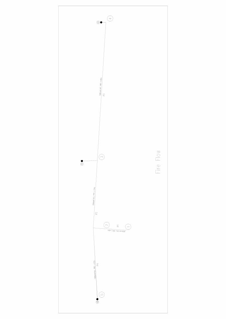
The source of water supply for the proposed development is from Node 1
(refer to water supply overall planning layout) and the residual head at that
tapping point is 70.00m.
3.2 Proposed Water Supply System
The proposed water supply system for the development consists of
200mm M.S. Pipe from the proposed water source (tapping point) to
supply to the proposed development.
The detailed engineering design for the water supply system and external
reticulation system is attached in Appendix B for the fire, normal and peak
analysis subsequently.

4.0 WATER DEMAND
The water consumption for the above developed area has been calculated based
on the guidelines provided by PUAS Berhad (Pindaan January 2000). The water
demand is based on the number and type of development units set out in the
estate structural plan submitted by the developer. The estimated water demand is
as shown in the Table 1.0
Description Person/
Unit Consumption
(litres/day/unit) Total
consumption (litres/day)
Total consumption (gallon/day)
Block A & B 280 1,500 420,000 92, 387.08
Surau 20 50 1,000 219.97
Tadika 1 30 1,500 329.95
Ruang Perniagaan
2 (225.17 m
2)
1,000/100m2 2,251.70 495.30
Gymnasium 1 (122.42 m
2)
1,000/100m2 1,224.20 269.29
Cafeteria 1 (205.55 m
2)
1,000/100m2 2,055.50 452.15
Pasar mini 1 (105.65 m
2)
1,000/100m2 1,056.50 232.40
Kolam renang 1 4500 4500 989.86
Dewan serbaguna
1 (213.10m2) 1,000/100m
2 2,131.00 468.75
Sum 435,718.90 95,844.76
Add 10% Losses 43, 571.89 9,584.48
Total 479,290.79 105,429.23
Table 1.0: Water consumption in a day.
Total Daily Water Consumption = 479,290.79 lpd = 105, 429.23 gpd
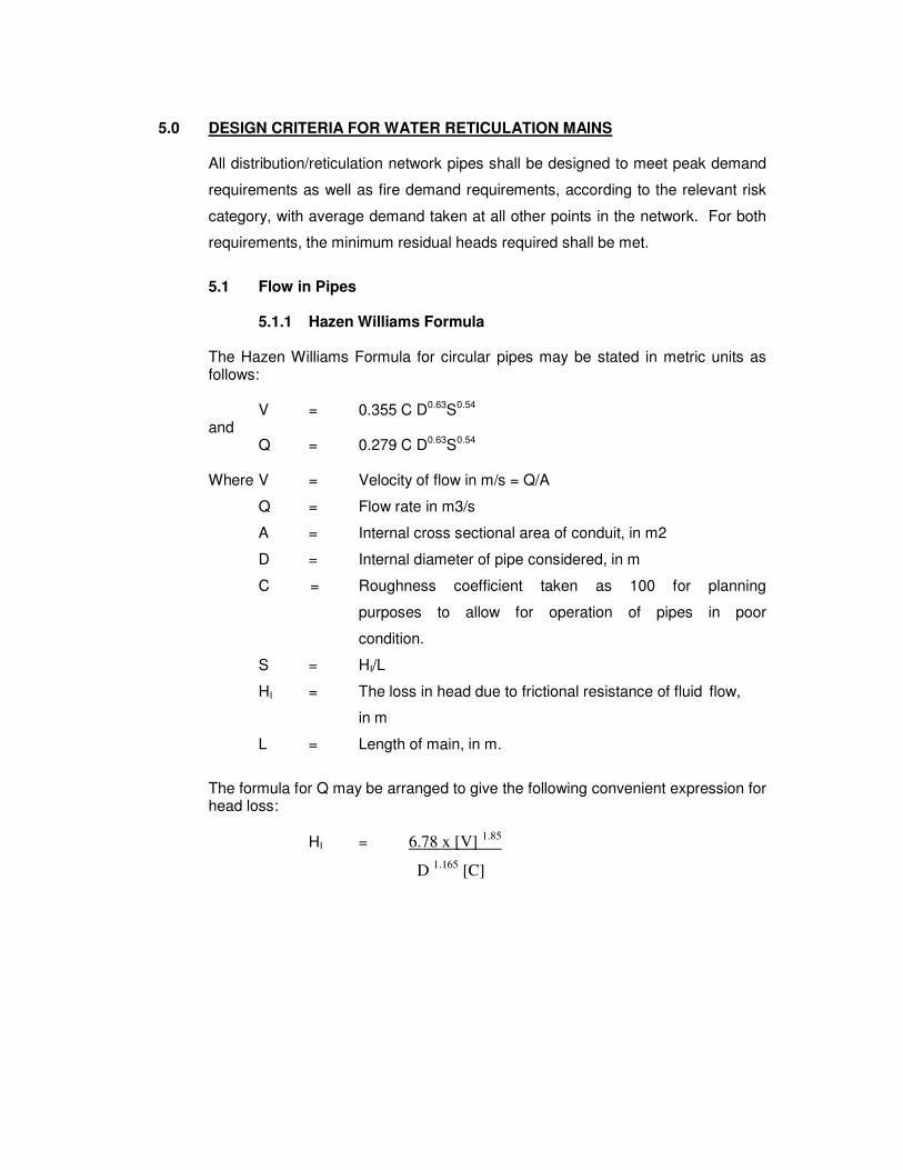
5.0 DESIGN CRITERIA FOR WATER RETICULATION MAINS
All distribution/reticulation network pipes shall be designed to meet peak demand
requirements as well as fire demand requirements, according to the relevant risk
category, with average demand taken at all other points in the network. For both
requirements, the minimum residual heads required shall be met.
5.1 Flow in Pipes
5.1.1 Hazen Williams Formula The Hazen Williams Formula for circular pipes may be stated in metric units as follows: V = 0.355 C D0.63S0.54 and Q = 0.279 C D0.63S0.54 Where V = Velocity of flow in m/s = Q/A
Q = Flow rate in m3/s
A = Internal cross sectional area of conduit, in m2
D = Internal diameter of pipe considered, in m
C = Roughness coefficient taken as 100 for planning
purposes to allow for operation of pipes in poor
condition.
S = HI/L
HI = The loss in head due to frictional resistance of fluid flow,
in m
L = Length of main, in m.
The formula for Q may be arranged to give the following convenient expression for head loss:
HI = 6.78 x [V] 1.85
D 1.165
[C]
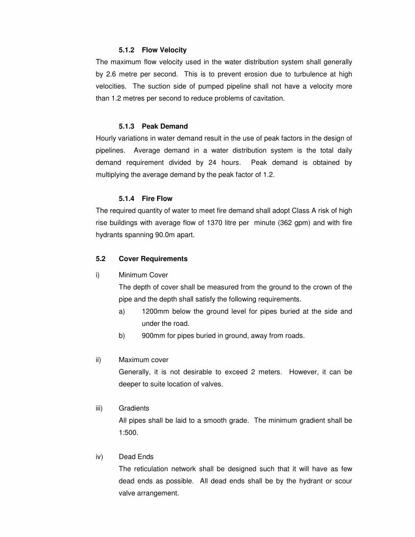
5.1.2 Flow Velocity
The maximum flow velocity used in the water distribution system shall generally
by 2.6 metre per second. This is to prevent erosion due to turbulence at high
velocities. The suction side of pumped pipeline shall not have a velocity more
than 1.2 metres per second to reduce problems of cavitation.
5.1.3 Peak Demand
Hourly variations in water demand result in the use of peak factors in the design of
pipelines. Average demand in a water distribution system is the total daily
demand requirement divided by 24 hours. Peak demand is obtained by
multiplying the average demand by the peak factor of 1.2.
5.1.4 Fire Flow
The required quantity of water to meet fire demand shall adopt Class A risk of high
rise buildings with average flow of 1370 litre per minute (362 gpm) and with fire
hydrants spanning 90.0m apart.
5.2 Cover Requirements i) Minimum Cover
The depth of cover shall be measured from the ground to the crown of the
pipe and the depth shall satisfy the following requirements.
a) 1200mm below the ground level for pipes buried at the side and
under the road.
b) 900mm for pipes buried in ground, away from roads.
ii) Maximum cover
Generally, it is not desirable to exceed 2 meters. However, it can be
deeper to suite location of valves.
iii) Gradients
All pipes shall be laid to a smooth grade. The minimum gradient shall be
1:500.
iv) Dead Ends
The reticulation network shall be designed such that it will have as few
dead ends as possible. All dead ends shall be by the hydrant or scour
valve arrangement.

5.3 Valve Chamber
All valves which are to be placed underground shall be housed in chambers.
There are three common types of valve chambers, namely precast concrete, brick
and reinforced concrete chambers.
Brick and reinforced concrete valve chambers shall have the following generally
features:-
i) The internal dimensions of the chamber shall depend on the size of valves,
fittings and joints to be placed in the chamber. The distance between the
wall and the edge of the joint shall be at least 150mm for pipes not
exceeding 450mm while pipes greater than 450mm shall have a distance
of at least 300mm. The chamber width or length width or length shall not
be smaller than 750mm.
ii) The base shall have a minimum thickness of 150mm.
iii) Valves shall be installed on mass concrete supports.
iv) Chambers deeper than 1.0 meter shall be provided with 20 mm diameter
wrought iron steps spaced at 300 mm interval.
v) Valve chambers are provided with covers, either or reinforced concrete,
mild steel or cast iron. Covers shall be supplied with lifting facilities. Mild
steel and cast iron covers shall be hinged and shall be designed for heave
duty.
vi) Scour valve chambers shall be provided with an outlet.
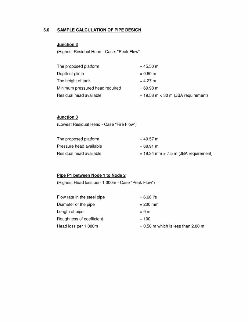
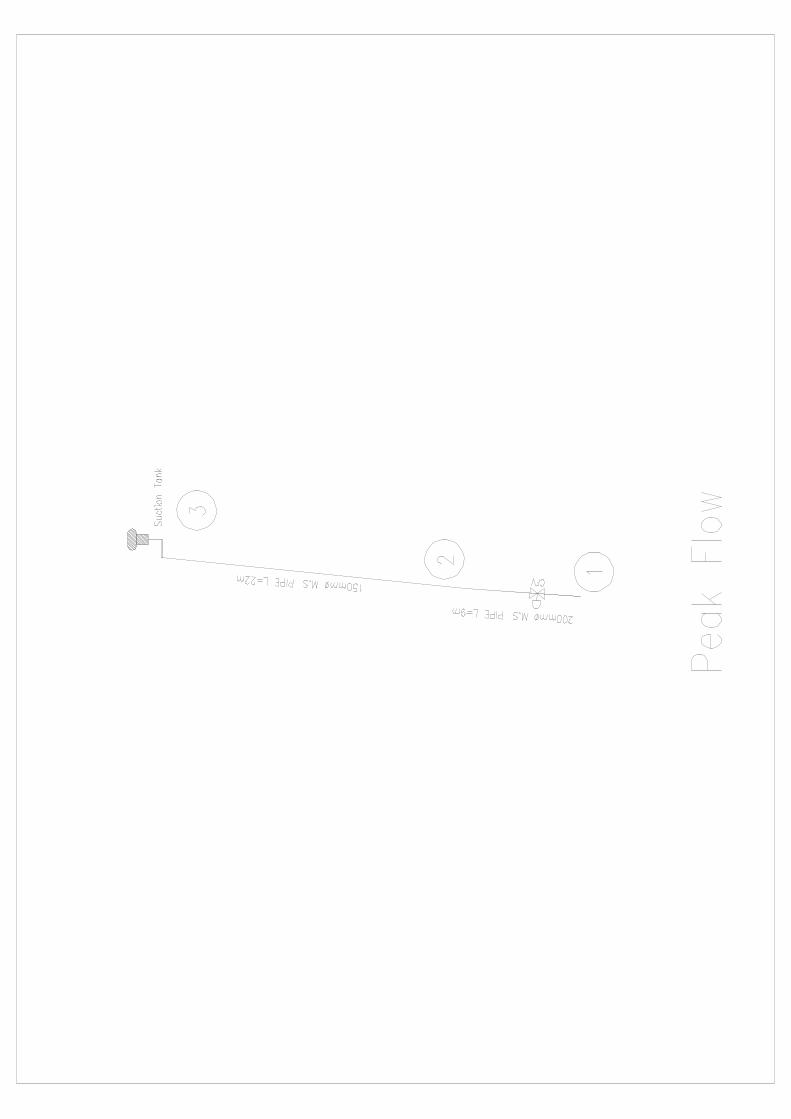
6.0 SAMPLE CALCULATION OF PIPE DESIGN
Junction 3
(Highest Residual Head - Case: "Peak Flow”
The proposed platform = 45.50 m
Depth of plinth = 0.60 m
The height of tank = 4.27 m
Minimum pressured head required = 69.98 m
Residual head available = 19.58 m < 30 m (JBA requirement)
Junction 3
(Lowest Residual Head - Case "Fire Flow")
The proposed platform = 49.57 m
Pressure head available = 68.91 m
Residual head available = 19.34 mm > 7.5 m (JBA requirement)
Pipe P1 between Node 1 to Node 2
(Highest Head loss per- 1 000m - Case "Peak Flow")
Flow rate in the steel pipe = 6.66 l/s
Diameter of the pipe = 200 mm
Length of pipe = 9 m
Roughness of coefficient = 100
Head loss per 1,000m = 0.50 m which is less than 2.00 m

APPENDIX A
KEY PLAN AND
LOCATION PLAN

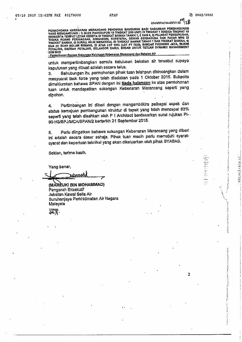
APPENDIX B
APPROVAL LETTERS
FROM SYABAS

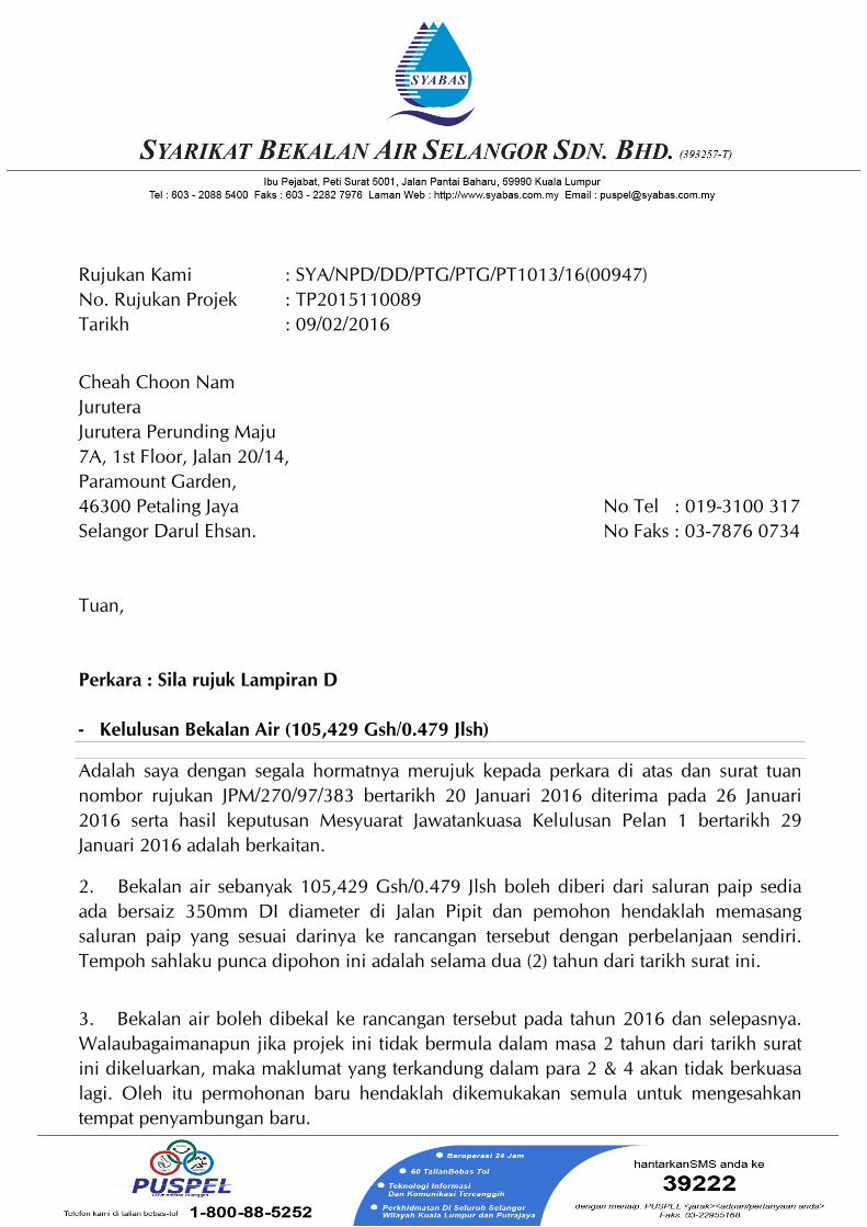
Rujukan KamiNo. Rujukan Projek
: SYA/NPD/DD/PTG/PTG/PT1013/16(00947): TP2015110089
Tarikh : 09/02/2016
Cheah Choon NamJuruteraJurutera Perunding Maju7A, 1st Floor, Jalan 20/14,Paramount Garden,46300 Petaling JayaSelangor Darul Ehsan.
No Tel : 019-3100 317No Faks : 03-7876 0734
Tuan,
Perkara : Sila rujuk Lampiran D
- Kelulusan Bekalan Air (105,429 Gsh/0.479 Jlsh)
Adalah saya dengan segala hormatnya merujuk kepada perkara di atas dan surat tuannombor rujukan JPM/270/97/383 bertarikh 20 Januari 2016 diterima pada 26 Januari2016 serta hasil keputusan Mesyuarat Jawatankuasa Kelulusan Pelan 1 bertarikh 29Januari 2016 adalah berkaitan.
2. Bekalan air sebanyak 105,429 Gsh/0.479 Jlsh boleh diberi dari saluran paip sediaada bersaiz 350mm DI diameter di Jalan Pipit dan pemohon hendaklah memasangsaluran paip yang sesuai darinya ke rancangan tersebut dengan perbelanjaan sendiri.Tempoh sahlaku punca dipohon ini adalah selama dua (2) tahun dari tarikh surat ini.
3. Bekalan air boleh dibekal ke rancangan tersebut pada tahun 2016 dan selepasnya.Walaubagaimanapun jika projek ini tidak bermula dalam masa 2 tahun dari tarikh suratini dikeluarkan, maka maklumat yang terkandung dalam para 2 & 4 akan tidak berkuasalagi. Oleh itu permohonan baru hendaklah dikemukakan semula untuk mengesahkantempat penyambungan baru.
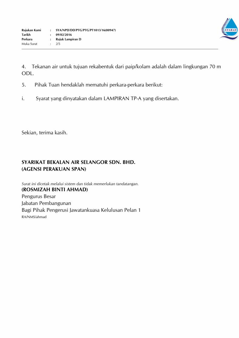
Rujukan Kami : SYA/NPD/DD/PTG/PTG/PT1013/16(00947)Tarikh : 09/02/2016Perkara : Rujuk Lampiran D Muka Surat : 2/5
4. Tekanan air untuk tujuan rekabentuk dari paip/kolam adalah dalam lingkungan 70 mODL.
5. Pihak Tuan hendaklah mematuhi perkara-perkara berikut: i. � Syarat yang dinyatakan dalam LAMPIRAN TP-A yang disertakan.
Sekian, terima kasih.
SYARIKAT BEKALAN AIR SELANGOR SDN. BHD.(AGENSI PERAKUAN SPAN)
Surat ini dicetak melalui sistem dan tidak memerlukan tandatangan.(ROSMIZAH BINTI AHMAD)Pengurus Besar Jabatan PembangunanBagi Pihak Pengerusi Jawatankuasa Kelulusan Pelan 1RA/NMS/ahmad
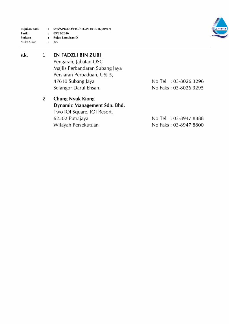
Rujukan Kami : SYA/NPD/DD/PTG/PTG/PT1013/16(00947)Tarikh : 09/02/2016Perkara : Rujuk Lampiran D Muka Surat : 3/5
s.k. 1. EN FADZLI BIN ZUBIPengarah, Jabatan OSCMajlis Perbandaran Subang JayaPersiaran Perpaduan, USJ 5, 47610 Subang JayaSelangor Darul Ehsan.
No Tel : 03-8026 3296No Faks : 03-8026 3295
2. Chung Nyuk KiongDynamic Management Sdn. Bhd.Two IOI Square, IOI Resort,62502 PutrajayaWilayah Persekutuan
No Tel : 03-8947 8888No Faks : 03-8947 8800

Rujukan Kami : SYA/NPD/DD/PTG/PTG/PT1013/16(00947)Tarikh : 09/02/2016Perkara : Rujuk Lampiran D Muka Surat : 4/5
s.d.k 1. Khor Tse TongKetua Wilayah SYABAS Petaling
2. Tuan Haji Ariff Bin IbrahimPengurus BesarJabatan Operasi dan Penyelenggaraan
3. Tn. Haji Mohd Suhaimi Bin RafiePengurus Besar KananBahagian GIS, Asset dan SCADA
- Keputusan ini merujuk kepada Mesyuarat JKP1 yang telah diadakanpada 29/01/2016
LAMPIRAN D
Rujukan Kami : SYA/NPD/DD/PTG/PTG/PT1013/16(00947)Tarikh : 09/02/2016Perkara : Rujuk Lampiran D Muka Surat : 5/5
PERKARA : CADANGAN PEMBANGUNAN PANGSAPURI 19 TINGKAT (280 UNIT) YANG MENGANDUNGI :-
1. � 3 TINGKAT SEMI BASEMENT TEMPAT LETAK KERETA DI TINGKAT BAWAH TANAH 1, 2 DAN 32. � BILIK MEKANIKAL DAN SURAU DI TINGKAT BAWAH TANAH 13. � 1 TINGKAT PODIUM KEMUDAHAN(PEJABAT PENGURUSAN, TADIKA, 2 UNIT RUANGPERNIAGAAN, GIMNASIUM, KAFETERIA, PASAR MINI, DEWAN SERBAGUNA, KOLAM RENANG DANBILIK MEKANIKAL) DI TINGKAT BAWAH4. � BLOK A-18 TINGKAT PANGSAPURI (140 UNIT) DI TINGKAT 1-185. � BLOK B-18 TINGKAT PANGSAPURI (140 UNIT) DI TINGKAT 1-18
DI ATAS LOT 1013 (PT 7026), JALAN PIPIT, BANDAR PUCHONG JAYA, PUCHONG, MUKIM PETALING,DAERAH PETALING, SELANGOR DARUL EHSAN UNTUK TETUAN DYNAMIC MANAGEMENT SDNBHD.
PIPE NETWORK ANALYSIS
H y d r a u l i c a n d W a t e r Q u a l i t y
A n a l y s i s F o r P i p e N e t w o r k s
V e r s i o n 2
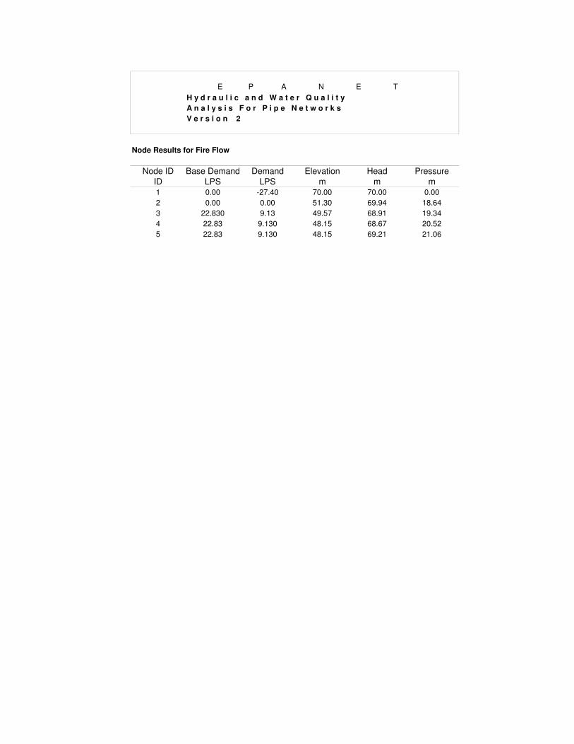
Node Results for Fire Flow
Node ID Base Demand Demand Elevation Head Pressure
ID LPS LPS m m m
1 0.00 -27.40 70.00 70.00 0.00
2 0.00 0.00 51.30 69.94 18.64
3 22.830 9.13 49.57 68.91 19.34
4 22.83 9.130 48.15 68.67 20.52
5 22.83 9.130 48.15 69.21 21.06
E P A N E T

H y d r a u l i c a n d W a t e r Q u a l i t y
A n a l y s i s F o r P i p e N e t w o r k s
V e r s i o n 2
Pipe Results for Fire Flow
LINK Length Diameter Flow Velocity Headloss
ID m mm LPS m/s m/km
P1 9 200 27.4 0.87 6.84
P2 54 150 27.4 1.03 13.11
P3 65 150 9.13 0.52 3.63
P4 33 150 9.13 0.52 3.63
E P A N E T

H y d r a u l i c a n d W a t e r Q u a l i t y
A n a l y s i s F o r P i p e N e t w o r k s
V e r s i o n 2
Node Results for Peak Flow
Node ID Base Demand Demand Elevation Head Pressure
ID LPS LPS m m m
1 0.000 -6.66 70.00 70.00 0.00
2 0.000 0.00 50.65 70.00 19.35
3 (Suction Tank) 5.547 6.66 50.37 69.95 19.58
E P A N E T

H y d r a u l i c a n d W a t e r Q u a l i t y
A n a l y s i s F o r P i p e N e t w o r k s
V e r s i o n 2
Pipe Results for Peak Flow
LINK Length Diameter Flow Velocity Headloss
ID m mm LPS m/s m/km
P1 9 200 6.66 0.21 0.5
P2 22 150 6.66 0.38 1.92
E P A N E T

WATER DEMAND

Wate
r C
on
sum
pti
on
for
Dyn
am
ic M
an
agem
ent
Sd
n. B
hd
.
Ite
mD
esc
rip
tio
nP
ers
on
/Un
itA
rea
(m
2)
Co
nsu
mp
tio
n (
Lite
r/D
ay
)T
ota
l C
on
sum
pti
on
(Li
ter/
Da
y)
To
tal
Co
nsu
mp
tio
n (
Ga
llo
n/D
ay
)
1B
lock
A &
B2
80
.00
-
1,5
00
.00
42
0,0
00
.00
92
,38
7.0
8
2S
ura
u2
0.0
0
-
50
.00
1,0
00
.00
2
19
.97
3T
ad
ika
1.0
0
-
30
.00
1,5
00
.00
3
29
.95
4R
ua
ng
Pe
rnia
ga
an
2.0
0
22
5.1
7
1
00
0/1
00
m2
2,2
51
.70
4
95
.30
5G
imn
asi
um
1.0
0
12
2.4
2
1
00
0/1
00
m2
1,2
24
.20
2
69
.29
6K
afe
teri
a1
.00
20
5.5
5
1
00
0/1
00
m2
2,0
55
.50
4
52
.15
7P
asa
r M
ini
1.0
0
10
5.6
5
1
00
0/1
00
m2
1,0
56
.50
2
32
.40
8K
ola
m R
en
an
g1
.00
-
4,5
00
.00
4,5
00
.00
9
89
.86
9D
ew
an
Se
rba
gu
na
1.0
0
21
3.1
0
1
00
0/1
00
m2
2,1
31
.00
4
68
.75
S
um
43
5,7
18
.90
95
,84
4.7
6
A
dd
10
% l
oss
es
43
,57
1.8
9
9,5
84
.48
To
tal
est
ima
ted
da
ily
co
nsu
mp
tio
n4
79
,29
0.7
9
10
5,4
29
.23


![Cybersecurity Games and Investments: A Decision Support ...pm/GameSecCameraready.pdf · Cavusoglu et. al. [11]compare a decision theory based approach to game theo-retic approaches](https://img.pdfslide.us/doc/110x75/5ea6acdc4fde4e1e1d519035/cybersecurity-games-and-investments-a-decision-support-pm-cavusoglu-et.jpg)