Embed Size (px)
Citation preview
Water Re-Use System for Industrial Discharger
Timothy J. St. Germain, P.E.
Senior Vice President
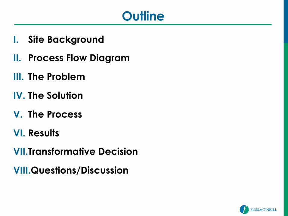
Outline
I. Site Background
II. Process Flow Diagram
III. The Problem
IV. The Solution
V. The Process
VI. Results
VII. Transformative Decision
VIII. Questions/Discussion
Windsor Locks, CT Facility
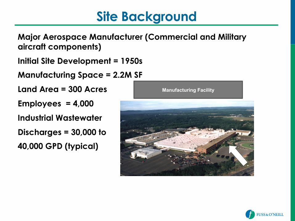
Site Background Major Aerospace Manufacturer (Commercial and Military aircraft components)
Initial Site Development = 1950s
Manufacturing Space = 2.2M SF
Land Area = 300 Acres
Employees = 4,000
Industrial Wastewater
Discharges = 30,000 to
40,000 GPD (typical)
Manufacturing Facility
Site Background
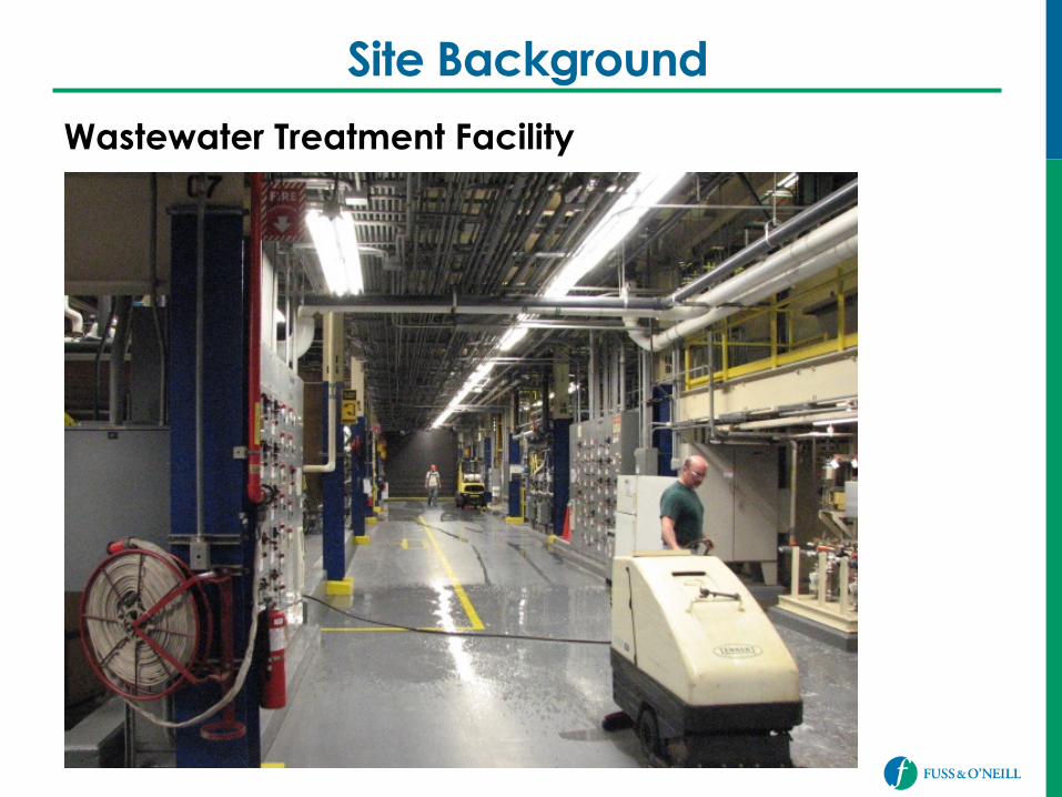
Wastewater Treatment Facility
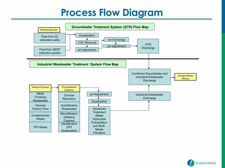
Process Flow Diagram
Flow from 22 extraction wells
Equalization
VOC Removal
pH adjustment
Ion Exchange
pH adjustment
Groundwater Treatment System (GTS) Flow Map
Flow from SEEP collection system
GTS Discharge
Metal Finishing
Wastewater
General Factory Flow
Containerized Waste
FPI Waste
Chrome Reduction
Microfiltration (Alkaline Cleaner)
Acid/Alkaline Wastewater
Ultrafiltration (FPI
Wastewater)
pH Adjustment
Equalization
Combined Groundwater and Industrial Wastewater
Discharge
Industrial Wastewater Discharge
Influent Sources
Influent Sources
Pre-treatment Systems
Advanced Treatment
(Metal Hydroxide
Precipitation and Multi-
Media Filtration)
Industrial Wastewater Treatment System Flow Map
Surface Water (River)
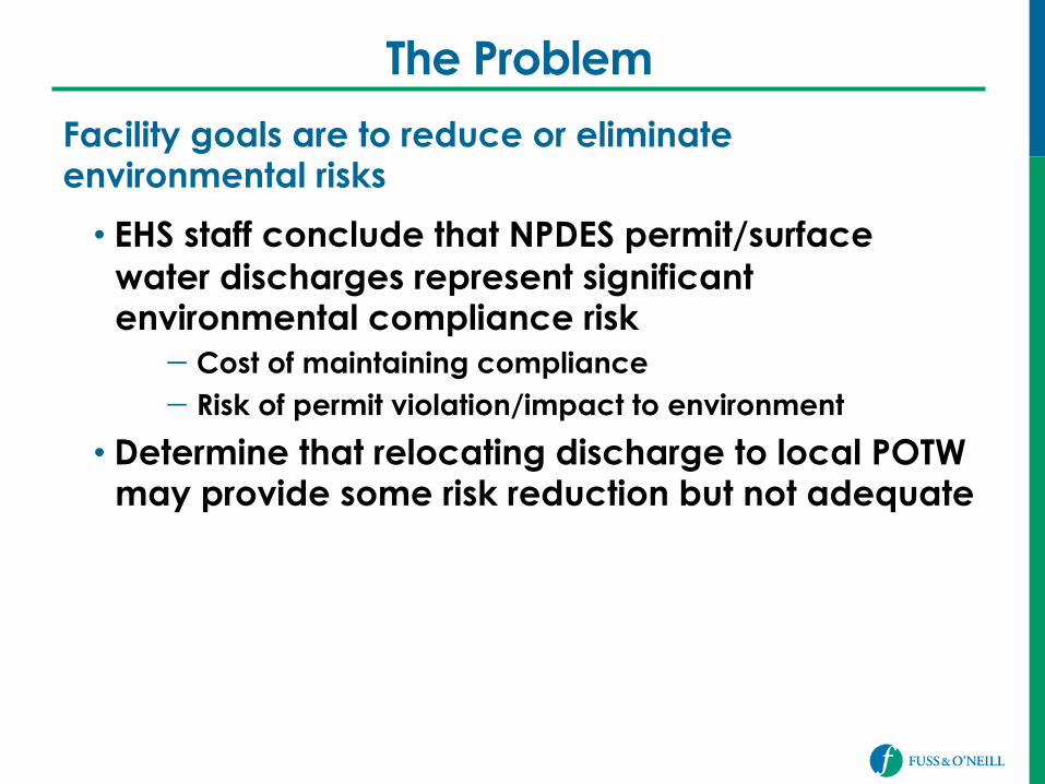
The Problem
Facility goals are to reduce or eliminate environmental risks
• EHS staff conclude that NPDES permit/surface water discharges represent significant environmental compliance risk − Cost of maintaining compliance − Risk of permit violation/impact to environment
• Determine that relocating discharge to local POTW may provide some risk reduction but not adequate
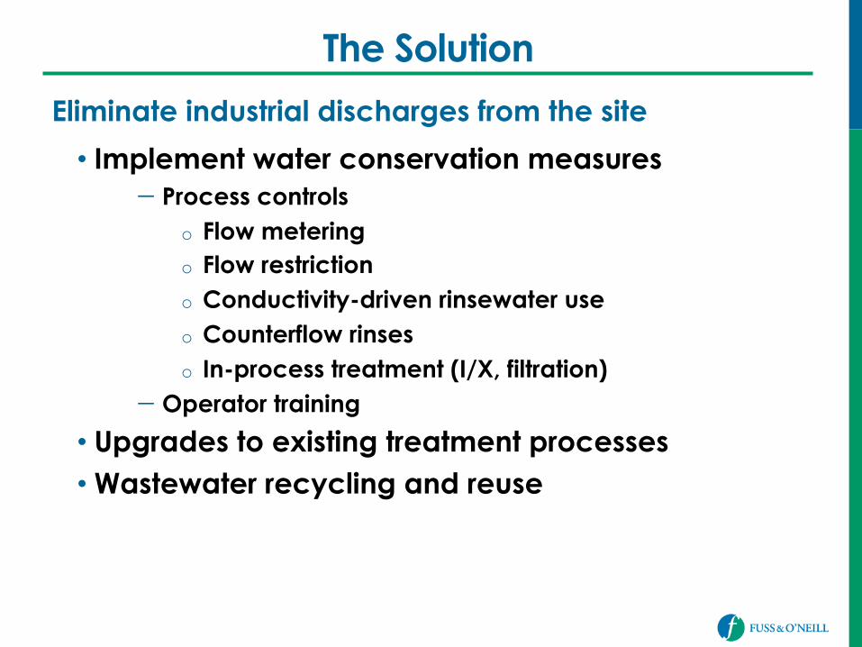
The Solution
Eliminate industrial discharges from the site
• Implement water conservation measures − Process controls
o Flow metering o Flow restriction o Conductivity-driven rinsewater use o Counterflow rinses o In-process treatment (I/X, filtration)
− Operator training
• Upgrades to existing treatment processes • Wastewater recycling and reuse
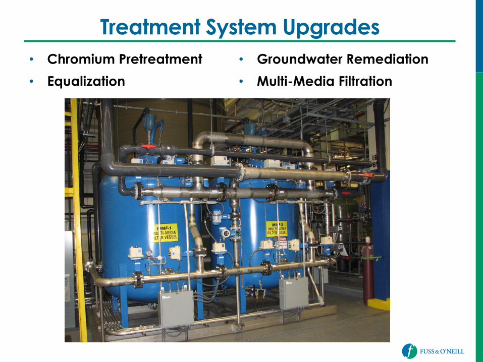
Treatment System Upgrades • Chromium Pretreatment
• Equalization
• Groundwater Remediation
• Multi-Media Filtration
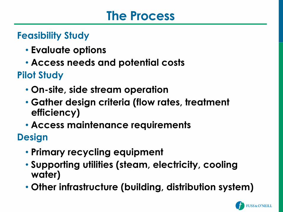
The Process Feasibility Study
• Evaluate options • Access needs and potential costs
Pilot Study
• On-site, side stream operation • Gather design criteria (flow rates, treatment
efficiency) • Access maintenance requirements
Design
• Primary recycling equipment • Supporting utilities (steam, electricity, cooling
water) • Other infrastructure (building, distribution system)
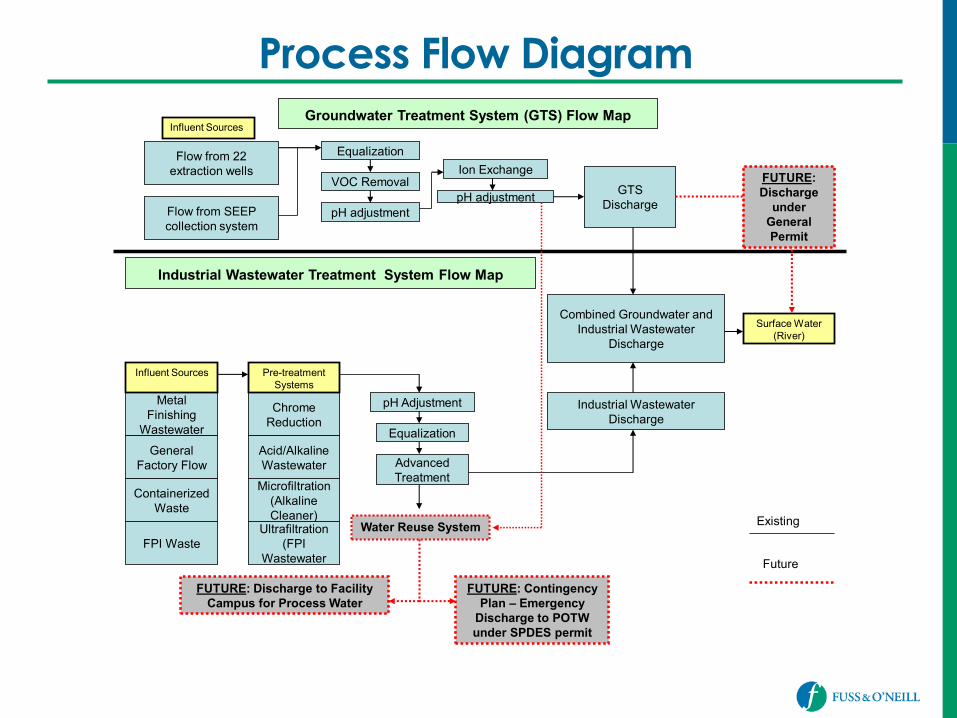
Process Flow Diagram
Flow from 22 extraction wells
Equalization
VOC Removal
pH adjustment
Ion Exchange
pH adjustment
Groundwater Treatment System (GTS) Flow Map
Flow from SEEP collection system
GTS Discharge
Metal Finishing
Wastewater
General Factory Flow
Containerized Waste
FPI Waste
Chrome Reduction
Microfiltration (Alkaline Cleaner)
Acid/Alkaline Wastewater
Ultrafiltration (FPI
Wastewater
pH Adjustment
Equalization
Combined Groundwater and Industrial Wastewater
Discharge
Industrial Wastewater Discharge
Influent Sources
Influent Sources
Pre-treatment Systems
Advanced Treatment
Industrial Wastewater Treatment System Flow Map
Water Reuse System
FUTURE: Discharge to Facility Campus for Process Water
Future
Existing
Surface Water (River)
FUTURE: Contingency Plan – Emergency
Discharge to POTW under SPDES permit
FUTURE: Discharge
under General Permit
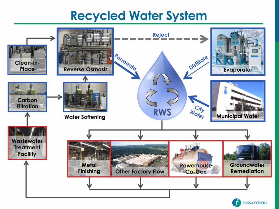
Recycled Water System
RWS
Reject
Evaporator
Municipal Water
Reverse Osmosis
Water Softening
Carbon Filtration
Clean-in-Place
Wastewater Treatment
Faclilty
Metal Finishing Other Factory Flow
Powerhouse Co-Gen
Groundwater Remediation
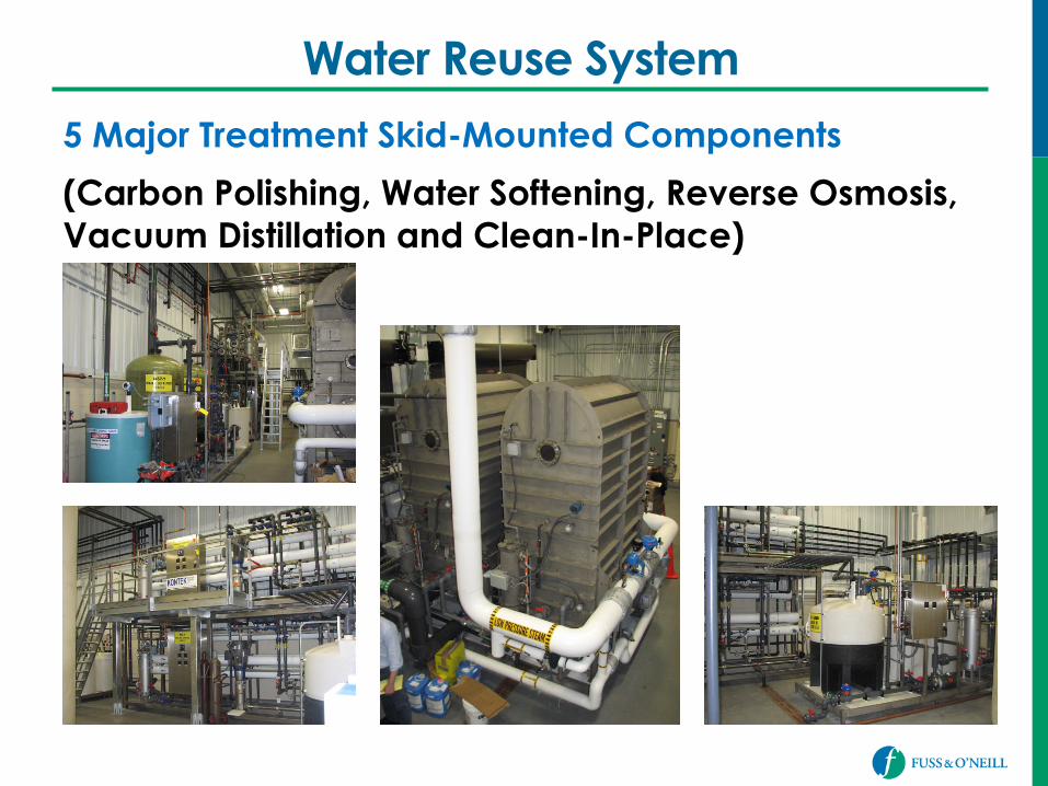
Water Reuse System
5 Major Treatment Skid-Mounted Components
(Carbon Polishing, Water Softening, Reverse Osmosis, Vacuum Distillation and Clean-In-Place)
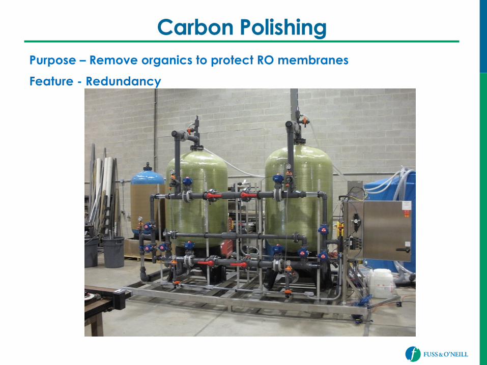
Carbon Polishing Purpose – Remove organics to protect RO membranes
Feature - Redundancy
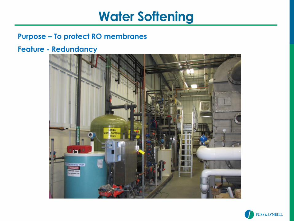
Water Softening Purpose – To protect RO membranes
Feature - Redundancy
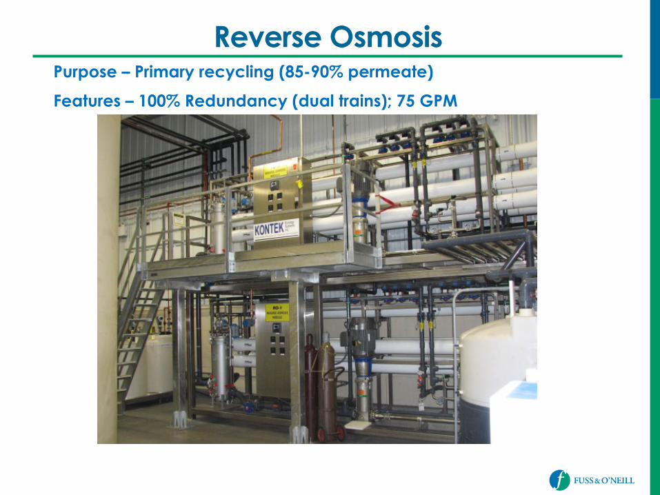
Reverse Osmosis Purpose – Primary recycling (85-90% permeate)
Features – 100% Redundancy (dual trains); 75 GPM
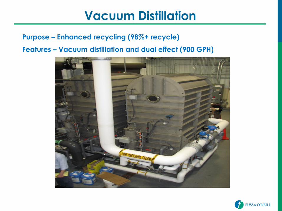
Vacuum Distillation
Purpose – Enhanced recycling (98%+ recycle)
Features – Vacuum distillation and dual effect (900 GPH)
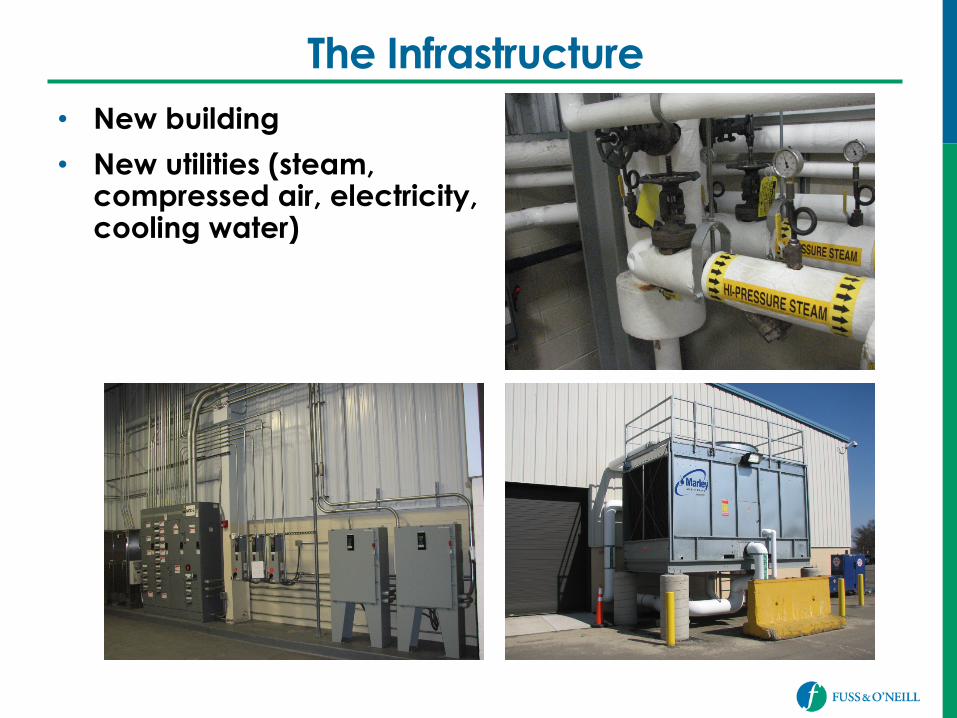
The Infrastructure • New building
• New utilities (steam, compressed air, electricity, cooling water)
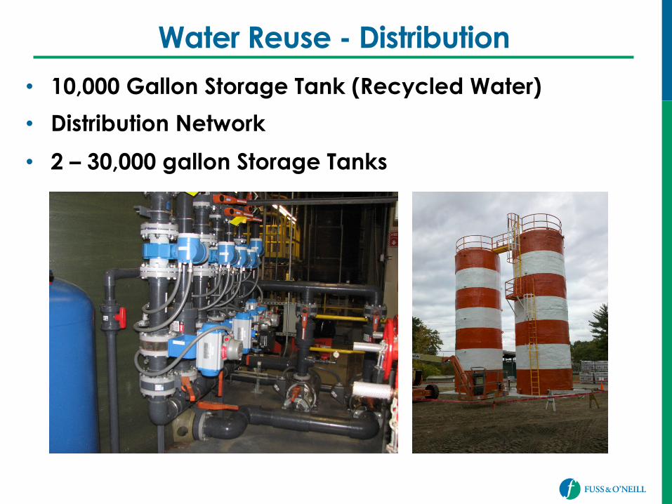
Water Reuse - Distribution
• 10,000 Gallon Storage Tank (Recycled Water)
• Distribution Network
• 2 – 30,000 gallon Storage Tanks
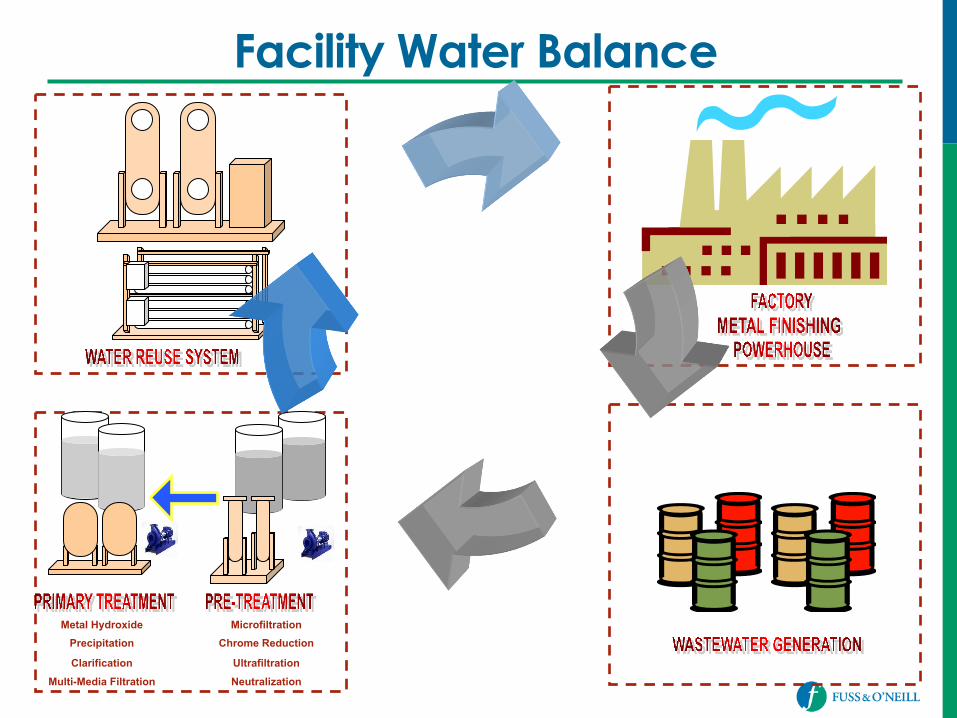
Microfiltration Chrome Reduction
Ultrafiltration
Neutralization
Metal Hydroxide Precipitation
Clarification
Multi-Media Filtration
Facility Water Balance
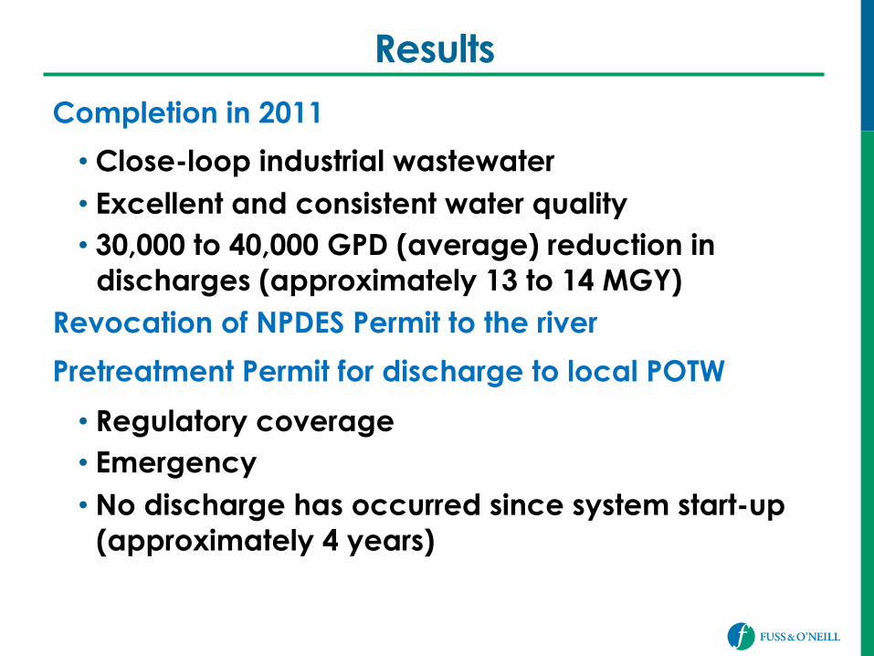
Results
Completion in 2011
• Close-loop industrial wastewater • Excellent and consistent water quality • 30,000 to 40,000 GPD (average) reduction in
discharges (approximately 13 to 14 MGY) Revocation of NPDES Permit to the river
Pretreatment Permit for discharge to local POTW
• Regulatory coverage • Emergency • No discharge has occurred since system start-up
(approximately 4 years)
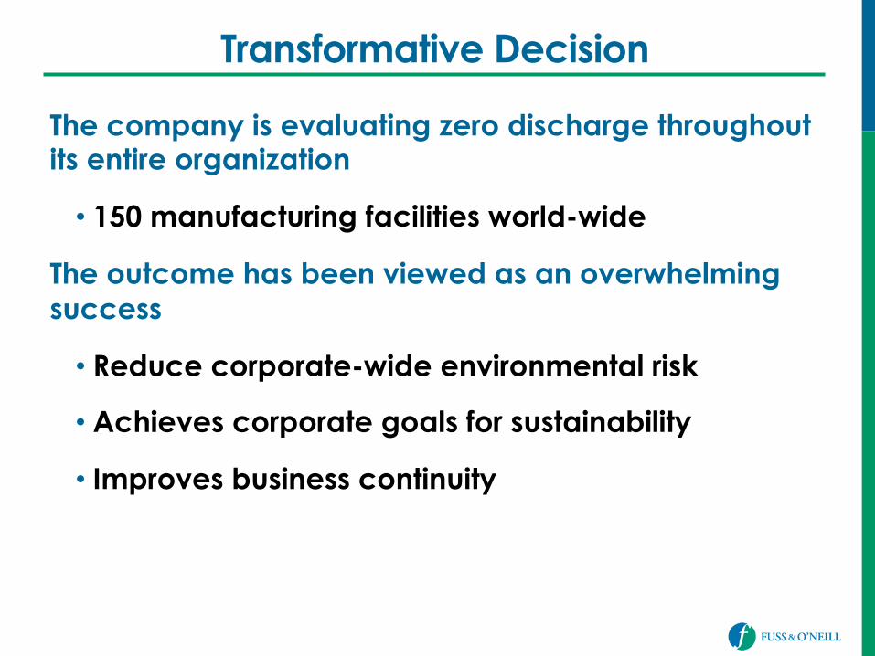
Transformative Decision
The company is evaluating zero discharge throughout its entire organization
• 150 manufacturing facilities world-wide
The outcome has been viewed as an overwhelming success
• Reduce corporate-wide environmental risk
• Achieves corporate goals for sustainability
• Improves business continuity
Acknowledgement
Primary Equipment Manufacturer:
Kontek Ecology Systems Inc.
Burlington, Ontario, Canada

Questions/Discussion
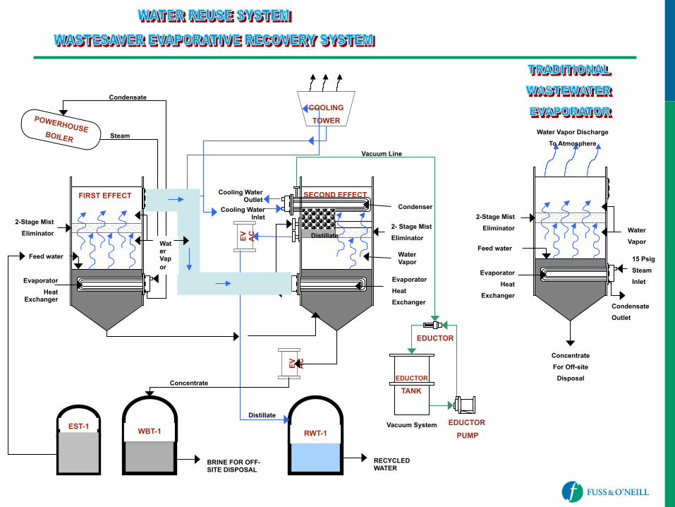
RWT-1
EV AC
POWERHOUSE BOILER
SECOND EFFECT
EV AC
EDUCTOR
TANK
Concentrate
For Off-site Disposal
2-Stage Mist
Eliminator
Water Vapor Discharge
To Atmosphere
Feed water
Evaporator
Heat Exchanger
Water
Vapor
15 Psig
Steam Inlet
Condensate
Outlet
2-Stage Mist
Eliminator
Feed water
FIRST EFFECT
Evaporator
Heat Exchanger
Condenser
Evaporator
Heat Exchanger
2- Stage Mist
Eliminator
Water Vapor
Cooling Water Outlet
Cooling Water Inlet
Distillate
Condensate
Steam
Distillate
RECYCLED WATER
WBT-1
BRINE FOR OFF-SITE DISPOSAL
Water Vapor
Concentrate
EST-1 Vacuum System EDUCTOR PUMP
EDUCTOR
COOLING TOWER
Vacuum Line