Embed Size (px)
Citation preview

A FEASIBILITY STUDY OF
WATER LIFTING TECHNOLOGY
IN THAILAND
Submitted to the National Energy Administration
Ministry of Science Technology and Energy
Under the Renewable Nonconventional Energy Project
Royal Thai Government US Agency tor International Development
ACKNOWLEDGEMENTS
From the National Energy Administration (NEA) acknowledgements are made to Mr Prapath Premmaini Secretary General Mr Tammachart Sirivadshyhanakul Deputy Secretary General and Mr Sompongse Chantavorapap Project Manager Dr Maurice L Alberton Senior Technical Project Management Expert is recognized for his advice on project implementation Also Ms Lana larsen and Ms Cheryl Messenger are recoqnied for their effortq in editing tais report
Deep gratitude is expressed tu Dr Krissinalong Kirtikara for the personal assistance he extended and to Dr Winsi liengeharorn sit who co-authored this report Recognition is ilso due Professor Somsak Panyashykeow Assistant Professor Banternq Suwantrakul Associate Professor Samorn Muttamara Mr Marcus Shermin and Br Douglas V Smith for their technishycal assistance
Acknowledgeinents are made to the Energy Economics Division of NEA for the socio-oconomic data aof the project areas Grati tude is also enpressed to the NEAs staff and those villagers wh h ve participated in construction and installation works
The United States Agency for International Development (USAID) is recognized for its financial assist ce without which the implementation of this water lifting project might lut hive been ccomplished
Finally thanks are extended to Ms Soipet Sajjanit and Ms Amphan Pomchaiyapoom for their wonderful typing wcrk
Oran Rutanaprakarn Component Leader Waterlifting Technology
Energy Research and Development Division NEA
iii
CONTENTS
Page
Title Page ents oAcknowledge oo oooo o o i
Acknowledgements ii Table of Contents
List of Tables
List of Figures
List of Photographs xvii
Terms and Abbreviations
Executive Summary vii
C(J-PTER I INTRODUCTION
A Overview of the Country 3
B Objectives of the Study 8
C Significance of the Study 8
D Scope of Work9D S -
9
CHAPTER II REVIEW OF LITERATURE
A Solar Energy Technology 13 1
B Wind Energy Technology 14
C Gasification Energy Technology 15
D Biogas Energy Technology 23
CHAPTER III BASIC DESIGN OF THE STUDY
A solar Pumping System 29
B Wind Turbine Pumping System
C Gasification Pumping System 40
D Biogas Pumping System 46
CHAPTER IV FIELD EXPERIMENTS
A Site Selection oooo - o 55
B Socio-Economic Characteristics of Ban Sukorn Tambon Chum Puang 56
V
CONTENTS (confinued) Eaye
C Socic-Economic Characteristic s of Ban Tha Yian Tambon Non Im 65
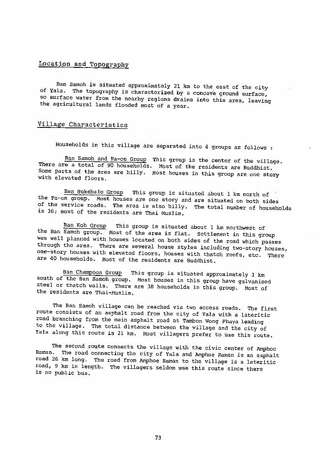
D Soci -Econmic Characteristics of Ban Sawoh Tambon Ta- t(n)ic 72
E Installation and Experimental Stud s
F Interpretatipl f Res Ilts 90
CHAPTER V DISCUSSION AND EAiUATION OF RESULTS
A Vl Tge Cooperation ]7
B- roblems Encountered in the implementation 117
118C Ecmnimic Ewo]ua~tiol o1C Ncimic rv-I I
CHAPTER VI CONCLUSIONS
A The Sa Jr Pumping System at Ban Sukorn 133
B The Souiar Pumping System at Ban Tha Yiam 133
C The Wind Turbine Pumping System at Ban Samoh 134
CHAPTER VII RECOMMENDATIONS 137
139REFERENCES
vi
EXECUTIVE SUMMARY
In this study the results from the implementation of four types of water pumping systems are presented These include the solar pumping wind turbine pumping gasifier and biogas pumping systems These pumping projects were implemented with firancial assistance from the US Agency for International Develoonent (USAID) Among these four pumpshying systems only the sol]a and wind turbine pumping systems hve been installed to date
One 700-watt solar pup was installed to pump water From a ground water well at Ban Tha Yiam Sakon Nakhon Province for domestic conshysumption The vo-ume rppro3imate~ywith lifting headpumping was 6nday a of 215m The investment cost of this solar pump was 357550 Baht (US $ 15546) of which 235980 Baht (US$ 10260) was contributed by USAID An economic analysis revealed that the benefit-cost ratio (BC) of this solar pump was 0491 and that the solar pumping system is not yet economically feasible This is due to the hioh cost of the solar array
The other 4300-watt solar pump was installcd at Ban Sukorn Nakhon Ratchasima Province to pump water from a storac-e pond for irrigation purposes The pumping volume was estimated to ne ahout 480 m3 day with a lifting head of 50 m The investment cost was 1094555 Baht (US $47589) of which 944127 Hihlt (US 41049) was contributed by USSID An economic analysis showed that the benefit-cost r ttio of this solar pumping system wcas 0421 and that the installed system is not economishycally feasible
Three windmills were installed at Ban Samoh Yala Province to pump water for irrigation purposes These included two multi-blade windmills and one VITA windmill The investment acsts of these three windmills were 3000 Baht (US $ 3478) 56000 Baht (US $ 2435) and 45380 Baht (USF 1993) respectively These windmill costs were contributed by USAD An economic analysis revealed that the wind turbine water pumping system was not economically feasible with the benefit-cost ratio ranging from 0471 to 0811
From this study it can be conzluded that the solar and wind turbine pumping systems are not economically feasible at the present time due to their high investment costs The promotion of these types of renewable energy projects should be postponed until the price of the solar array and the windmills are decreased to a certain value
Though the installed water pumpinu systems were found to be not feasible from an economic point of view there still exist some indirect benefits from such a fevelopment These include initiating the role of cooperation in rural developmeat fostering close cooperation between local people and the governmet and initiating the application of energy technologies for the rural people
vii
CONCLUSIONS
The study on the development of these renewzable evergy projects leads to the following conclusions
A THE SOLAR PUMPING SYSTEM AT BAN SUK3RN
This solar pumping system hu-been pLanned to pump aiater from the Pradok Reservoir for irrigating -he agricuitural lands n Bat Sukurn Nakhon Ratchasima Province There are a total of 112 households with 646 residents in this village Most of the villagers are farmers Rice is the dominant crop The system is designed so that the nominal maximum power at the standard condition of solar array (100 nWcm2 at 250 C) is
not less than 4300 Watts- Four sets of solar arrays DC motors and self-priming centrifugal pumps were instalied Each solar array consists of 32 modules of solar cells The designed pumping discharge is 480 m3day at 50-m lifting head
The total cost of this system excluding the cost cf the irrigation canal was 1094555 Baht (US$ 47589) of which 944127 Baht (US$ 41049) was contributed by USAID An economic analysis shows that the benefitshycost ratio of this solar pumping system is 0421 and that the installed system is not economically feasible
Due to a delay in constructing the irrigation ca ial this solar pump has not yet been operational
B THE SOLAR PUMPING SYSTEM AT BAN THA YIAM
This system was installed to pump water from a ground water well to serve the villagers in Ban Tha Yiain Sakon Nakhon Province There are 57 households with 347 residents in this village Agriculture is the main occupation of the villagers Rice is the dominant crop grown in this area The installed system has been designed so that the nominal maximum power at the standard condition of solar array is not less than 700 Watts A solar array with 18 modules of solar cells was installed together with a DC motor and a screw-type pump The designed flow rate
3was 10 m day at a 215 m head However due to an increase in the drawshydown level in the ground water well the daily pumping discharge was approximately 6 m3 day The results obtained from the test-run show that the overall efficiency of this system varies between 09-16 Its value decreases as the solar panel temperature increases
viii
The total investment cost for this solar pumping system was 357550Baht (US$ 15546) of which 235980 Baht (US$ 10260) was contributed by USAID An economic analysis reveals that the benefit-cost ratio of this solar system was 0491 and that the system is not economically feasible
C THE WIND TURBINE PUIPING SYSTEM BANAT SAMOH
Two multi-bladc and one VITA windmill were install-d at Ban Samoh Yala Province to pump water from storage ponds for irrigating the villageagricultural area There are 204 households with 868 residents in this village Most of them are farmers Rice and rubber are the main crops grown in this area
The test run of these windmills showed that the windmill speedsand the pump discharges increased linearly with the wind speed For the large multi-blade windmill the monthly pump discharge was 3274 m at a mean wind speed of 2 ms ano the value 3increased to 667 m with a mean wind speed of 6 ms The overall efficiency decreased as the wind speed increased A value of 14 was computed for a wind speed of 2 mis The volumetric efficiency of the pump unit was as high as 98-99
For the VITA windmill the measured monthly discharge was 5500 m3 at a mean wind speed of 3 ms and 3the value increased to 12500 m at a mean wind speed of 6 ms The overall efficiency also decreased as the wind speed increased A value of 33 was computed for a wind speedof 4 ms The PVC ladder pump was used with this windmill The volumetric efficiency was 71 at a wind speed of 2 mis and the value decreased to 63 as the wind speed increased to 6 ms
The investment costs of these three windmills were 80000 Baht (US$ 3478) 50000 Baht (US$ 2435) and 45830 Baht (US$ 1993) forthe two multi-blade windmills and the VITA windmill respectively Thesewindmill costs were contributed by USAID An economic analysis reveals that the benefit-cost ratio of these windmills varied from 0471 to 0811 and this showed that the wind turbine pumping system is not econoshymically feasible
ix
RECOMMENDATIONS
The study on the implementation of these pumping systems can lead
to the following recommendations
Since the solar pumping systems are not financialL feasible (ccepared to diesel engine-pumping sstem) at the presen time the promotion of this
energy technology should he limited until the cost of the solar arzay is
value or benefit from having water for irrigationdecreased to a certain shows that it Ls suitable for rural development
More research shoald be conducted to investigate the performance
of various components of the system to obtain data neces-iry for future
problems which might be eLountered in
project designs and to study the
the operation and maintenance of such a system
Lathera The investment costs of the installed windmills are
this time which makes the project not financially feasiblehigh at
However the benefit-cost ratios show that the utilization of windmills
are near-ter feasible Therefore more development of tne windmill
aim of reducing the construction costs and inshy
creasing the overall efficiency should be made with an
Since there are some indirect benefits resulting from the particishy
pation of the villagers the system should be maintained and improved so
lifting technology would be self-sustaining
that the utilization of the water
o The project would be more successful if some viliagers were trained
the testing runsduring the install3 ion sf the systems and curing
Monitoring activities sAould se continued to obtain further information
concerning bemefits on income resulting from providing water for irrigation
since the water lifting project needs considerable time to obtain information
after installation
Efficient utilization of pumped water should be emphasized and
villagers should be educated along these lines
Villagers needs and willingness to participate in the project should
be carefully studied during the site selection phase in order to assure a more
successful outcome during implementation
x
LIST OF TABLES
Table Title Page
11 Yield and Production of Major Crops (1980) 6
12 Total Agricultural Area VS Irrigated Area 7
21 Average Wind Power Potential 16
22 Windmills Used for Water Pumping in Thailand 17
23 Area and Productiity of Forests in Thailand 18
24 Yield of Selected Fast Growirl Trees 19
25 Research and Development Activities in Thailand 20
26 Number of Biogas Digesters in Thailand 24
27 Diogas Consumption for Typical Equipment 25
31 Technical Data of Thai USAWindmill 39
32 Volatile Solid Loading Rates Used in Various Biogas Plants 47
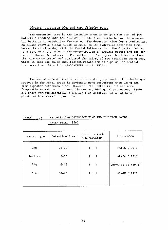
33 The Operating Detention Time and Dilution Ratio 48
34 Methane Gas Consumption for Various Gas Facilities 49
35 Weight of Excreta Produced per Day by Different
Animals 50
41 Main Occupation of Household Heads 58
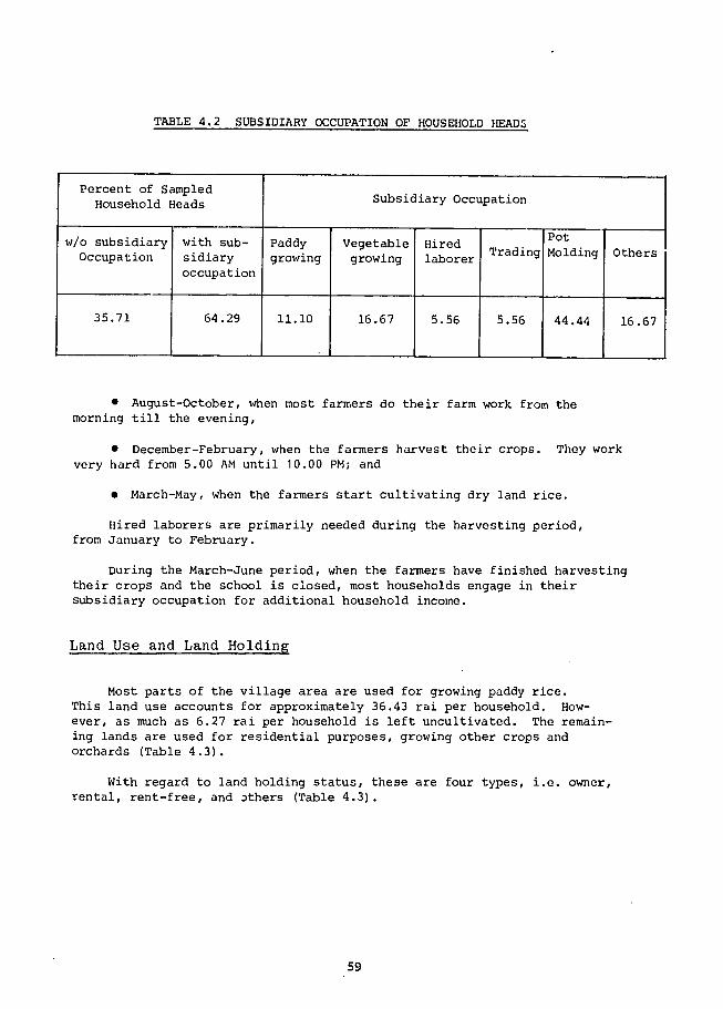
42 Subsidiary Occupation of Household Heads 59
43 Land Use and Land Holdings 60
44 Agricultural Production and Incomes in Ban Sukorn Village 61
45 Agricultural Input for Various Types of Crops Grown in Ban Sukorn Village 62
46 Annual Incomes from other Occupations 63
47 Household Expenditures 64
48 Main Occupation of Household Heads 67
49 Subsidiary Occupation of Household Heads 67
xi
LIST OF TABLES (continued)
Table Title Page
410 Land Use and Land Holdings in Ban Tha Yiam Village 68
411 Agricultural Input (Baht per Rai) 69
412 Agrioultiral Input (Baht per Household per Annum) 69
413 Agricultural Production and Annual Income 70
414 Annual Net Income from Agriculture 70
415 Annual Incomes from Other Occupations 71
416 Household Expenditures 71
417 Rice Production and Annual Income 75
418 Rubber Production and Annual Income 76
419 Agricultural Gross Income 77
420 Agricultural Net Income 77
421 Non-agricultural Net Income 77
422 Total Net Income 78
423 Agricultural Input 78
424 Non-agricultural Expense 79
425 Total Household Expenditures 79
426 Test Data of Multi-Blade Windmill 99
427 Test Results and Foreczast for Multi-Blade Windmill 100
428 Test Data of VITA Windioill (Type V-20 B) 107
429 Test Results and Forecast for VITA Windmill 108
51 Cost of Solar Water Pumping System at Ban Sukorn 121
52 Innual Equivalent Cost of the Solar Pumping System at Ban Sukorn 122
53 Cost of Equivalent Diesel Pump 123
54 Annual Equivalent Cost of the Equivalent Diesel Pump 123
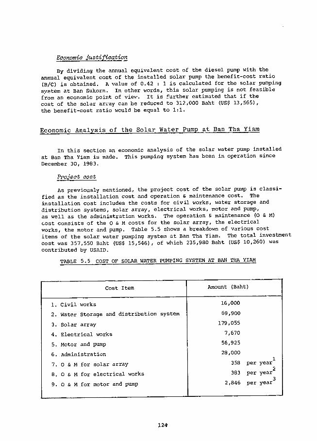
55 Cost of Solar Water Pumping System at Ban Tha Yiam 124
56 Annual Equivalent Cost of the Solar Pumping System at Ban Tha Yiam 125
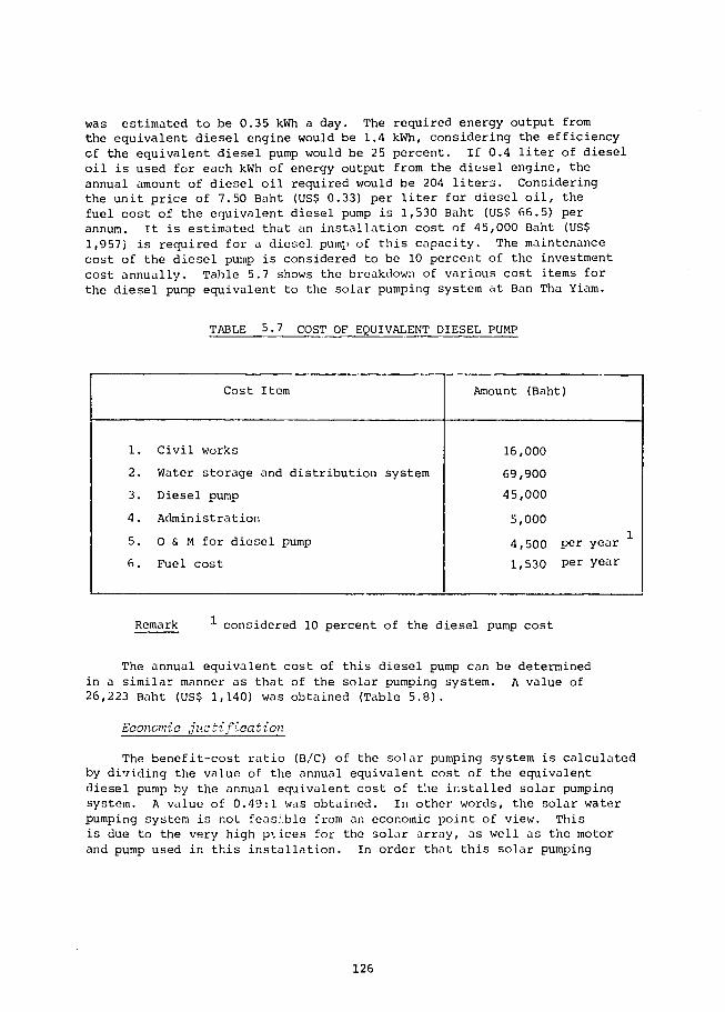
57 Cost of Equivalent Diesel Pump126
xii
LIST OF TABLES (Continued)
Table Title Page
58 Annual Equivalent Cost of the Equivalent Diesel Pump 127
59 Annual Equivalent cost of the Installed Windmills 128
510 Annual Equivalent Cost of the Diesel Pump Equivalent to the Installed Multi-Blade Windmill 129
511 Annual Equivalent Cost of the Diesel Pump Equivalent
to the Installed VITA Windmill 130
xiii
LIST OF FIGURES
Figure Title Page
31 Block Diagram of Gasifier Pumping System 41
41 Typical Curve of Solar Flux Against Time ac Ban Tha Yiam 92
42 Pumping Flow Rate VS rime at Ban Tha Yiam 93
43 Cumulative Energy on Solar Array at Ban Tha Yiam 94
44 Cumulative Pump Discharge at Ban Tha Yiam 95
45 Overall Performance Efficiency VS Solar Flux 96
46 Relationship Between Pump Discharge and Wind Speed
(Multi-Blade) 01
47 Relationship Between Windmill Speed and Wind Speed (Multi-Blade) 102
48 Relationship Between Monthly Pump Discharge and Mean Wind Speed (Multi-Blade) 103
49 Relationship Between Overall Efficiency and Wind Speed (Multi-Blade) 104
410 Relationship Between Volumetric Efficiency and Wind Speed (Multi-Blade) 105
411 Relationship Between Pump Discharge and Wind Speed
(VITA) 109 412 Relrtionship Between Windmill Speed and Wind Speed
110(VITA)
413 Relationship Between Monthly Pump Discharge and Meai Wind Speed (VITA) 111
414 Relationship Between Overall Efficiency and Wind Speed
112(VITA)
415 Volumetric Efficiency of PVC-Ladder Pump 113
xv
LIST OF PHOTOGRAPHS
Photo Title Page
41 The Pradok Reservoir Ban Sukorn 81
42 Villagers Participation 81
43 Land Preparatien at Ban Sukorn 82
44 Concrete Base ConstructioD at Ban Sukorn 82
45 Solar Panel Installation at Ban Sukorn 83
46 The 4300 Wp Solar Cell Pumping System at Ban Sukorn 83
47 Ban Tha Yiam Sa)on Nakhon Province 84
48 Solar Pump at Bar Tha Ylam 85
49 Main Storage Tank at Ban Tha Yiam 85
410 Water Utilization at Ban Tha Yiam 86
411 Bamboo Blade VITA Windmill at Ban Samoh 87
412 Large Multi-Blade Windmill at Ban Samoh 88
413 Small Multi-Blade Windmill at Ban Samoh 89
414 Villagers participation at Ban Samoh 90
xvii
TERMS AND ABBREVIATIONS
AC =
amp =
BC =
BOD =
Btu =
bhp =
C=
COD =
CN =
cm =
DC =
ft =
g =
HP =
hr =
in =
J =
kg =
km =
kW
kWh =
lb =
it =
M=
MSL =
MW =
M6 =
m =
mm =
min =
mW =
alternating current
ampere
benefit-cost ratio
biochemical oxygen demand
British thermal unit
brake horsepower
degree Celsius
chemical oxygen demand
carbon-nitrogen ratio
centimeter
direct current
foot
gravitational acceleration
horsepower
hour
inch
joule
kilogram
kilometer
kilowatt
kilowatt-hour
pound
liter
million Baht
mean sea level
megawatt
Mathayom 6
meter
millimeter
minute
milliwatt
xix
NEA =
O amp M =
P6 =
ppm =
rpm =
s =
UNDP =
V =
VS =
W =
Wp =
wt -
National Energy Administraticn
operation and maintenance
Prathom 6
part per million
revolution per minute
second
United Nations Development Programme
vClt
volatile solid
watt
peak watt
weight
xx
CHAPTER 1
INTRODUCTION
INTRODUCTION
This report summarizes the results of the installation operationand maintenance studies of water pumping systems This project was impleshymented with financial support from the United States Agency for Intershynational Development (USAID) and with technical assistance from the Nationshynal Energy Administration (NEA) Four types of water pumping systemswere considered at the beginning stage of the project These were thesolar water pumping system wind turbine water pumping system gasifierwater pumping system and biogas water pumping system Two solar water pumps and three wind turbine water pumps were installed and operated
A OVERVIEW OF THE COUNTRY
In this section a general description of the geographic and climaticconditions energy and agricultural situation of Thailand is providedto show the background of the country and the need to search for renewable energy sources rather than relying on the fuel oil which must be imported
Geographic and Climatic Condition of Thailand
The Kingdom of Thailand is located in the Indochina penninsulawithin the Southeast Asian continent Her boundary borders Burma andLaos to the north Laos and Kampuchea to the east Burma to the westand Malaysia to the south The specific location is given as betweenlatitudes 50 37 and 20 27 north and between longitudes 970 22 and 1051 37 east
Lying between 6 and 20 degrees north latitude with a rainy seasonfrom mid-May to early November Thailands climate is warm and moist Four torrential rivers the Ping Wang Yom and Nan that rise in thehigh mountains of the north descend through the North and Central secshytions of Thailand flow through the loam-filled delta and empty intothe Gulf of Thailand ThiE low flat area is known as the Central PlainsSoon after entering the plain the four rivers join to form the principalriver of the country the Chao Phraya River This flows for 77 km in a single course and then braids into several channels across the floodplain These reunite after being joined by lesser tributaries andflow into the gulf in two main channels the Chao Phraya and the Thachin River
3
The southwest and northeast monsoons exert a dominant influence on the climate of Thailand The southwest monsoon flowing from the Indian Ocean brings the warm and moist air mass to the country and norshymally extends from about mid-May to October During this period local atmospheric disturbances are common and quite frequent They are geneshyrated in the form of atmospheric low pressure cells of rather short durashytion They are also the chief contributors of rainfall over the country and the basin as well As the season progresses cyclonic storms usually originate in the west Pacific Ocean and the China Sea These storms occasionally approach the basin from the east but before reaching the basin they cross the mountains of Laos and Kampuchea where a lot of their energy is dissipated
With the retreat of the southwest monsoon the rain decreases rapidshyly and the northeast monsoon flowing from the cold and dry Asian mainland starts the winter from November to February There is very little or no rain during this period During the months of March to mid-May the weather is hot and dry it is gradually warmer from the start and April appears to be the hottest month of the year However at the end of this period there will be occasional light rain known as the pre-monsoon rain
According to the above climatic conditions the climate of the basin can be separated into two seasons wet and dry seasons by the characshyteristic of rainfall distribution The wet season is generally defined from May to October and the dry season is from November to April
Thailands Energy and Agricultural Situations
Thailands economics are primarily based on agriculture Rice is vhe main crop Fuels other than wood are mostly imported In this section the energy and agricultural situations of Thailand are briefly described
Thailand-energ situation
Energy is recognized as one of the most essential elements in the development of a country Thailand has undergone several national economic and development plans since 1961 These development activities have resulted in a rapid increase in energy demand by approximately 8 fold during the past 20 years from 2231 million liters of crude oil equivalent in 1962 to 17489 million liters in 1981 Similarly the energy consumption per capita increased approximately 5 fold from 760 liters of crude oil equivalent in 1962 to 3666 liters in 1981
4
Statistics show that Thailand depends heavily on imported crude oil and petroleum products from approximately 50 of the total energy consumption in 1962 to 80 in 1981 An insufficient supply of indigeneous energy has had shy z rious effect cn the national economy The energy import bill in the year 1982 accounted for 587992 M$ or approximately 38 of the total import bill
As a result of the world-wide energy crisis during 1973 the governshyment put great emphasis on tho development of indigeneous energy resources and energy conservation scrategies This policy is well recognized in the Fifth National Social and Economic Development Plan The target can be summarized as follows
0 The energy consumption growth rate has been set at not more than 48 percent per annum
0 The petroleum import is fixed at 3 peicent or less
0 The share of petroleum in the total energy consumption is to be reduced to 46 percent by the end of this plan (1986)
The development of natural gas in the Gulf of Thailand is to be accelerated in order to yield 525 million cuft per day by 1986 A gas separation plant of 350 million cuft capacity is Plso to be comshypleted by that year
The hydroelectric power capacity shall be doubled by 1986 from 1269 MW in 1980 to 2013 MW in 1986
Electricity generation from indigeneous lignite shall be inshycreased from 210 MW in 1980 to 885 MW in 1986
0 Ninety-two percent of the rural villages in Thailand shall be electrified by the end of the plan from 18511 villages in 1980 to 50034 villages in 1986
Petroleum reserve and refinery capacity shall be increased from 36 to 60 days and from 176000 barrels per day to 280000 barrels per day respectively
0 Other new and renewable energy resources such as ethanol fast growing trees mini-hydro biogas agricultural wastes wind solar etc shall be developed and utilized at the annual equivalent of 220shy290 million liters of crude oil by 1986
AgricuZtu2raZ situation
Thailand is an agricultural country Agricultural products have been major exports from Thailand for several decades Rice is the majorproduction item followed by rubber maize and cassava Table 11 shows the yield and production of major crops in Thailand in 1980
5
TABLE 11 YIELD AND PRODUCTION OF MAJOR CROPS (1980)
Crops
Paddy (rice)
Sugar Cane
Cassava
Maize
Coconut
Kenaf
Rubber
Mung beans
Ground nuts
Sorghum
Soy beans
Cotton
Castor beans
Tobaccc
Sesame
Need for Irrigation
Area Planted
(i0 Rai )
47400
738
1194
4250
1856
2356
7775
1300
644
219
300
581
231
138
163
Yield
(kgrai)
2829
69179
25792
4000
3885
1582
363
1307
1926
3200
1600
757
1286
1170
Production
(106 Tons)
1341
5102
3079
1700
721
373
281
170
124
07
048
044
037
020
019
Agricultural production is considered as a national economic indicashytor of the country However in recent years the agricultural economic growth rate has increased very slowly Agricultural yields have remained relatively constant and in some cases have decreased The growth in agricultural output is only due to an expansion of farm land area
With regard to the national interest the expansion of farm land area will contribute serious future problems to the country ie deshyforestation It is therefore necessary to promote and to convince farmers to use other means to increase agricultural yield such as irrigation fertilization mechanization proper uses of pesticides etc
6
Lack of irrigation is generally recognized as an important obstashycle for improving agricultural yields Irrigation can be Achieved by many different approaches eg large reservoir and irrigation canal systems large electrical pumping stations small pumping system etc
Large srale irrigation project implementatinns are currently unoershyway by the Royal Irrigation Department and electricial pumping stations have been promoted successfully by the National Energy Administration Groundwater is one important water source for domestic consumption and irrigation use in many regions However it is suitable for small scale irrigation only and commonly a diesel pump is used in such development
Data on the total farm land area and the area served by existing irrigation projects are shown in Table 12 It was found that the area under irrigation is small compared to the overall agricultural area
TABLE 12 TOTAL AGRICULTURAL AREA VS IRRIGATED AREA
Region Agricvltural Area(106rai) Irrigated Area
rice other total x 106 rai Percent fiela crops
Northeast 292 195 487 16 329
Central 137 185 322 119 3696
North 125 171 296 18 608
South 36 87 123 07 569
Total 590 638 1228 160 1303
Paddy rice plantations are mostly rain-fed The average rainfall is 1500 mm and is sufficient for production of the first rice crop
For the second crop agricultural activities are practiced only in irrigated areas approximately 16 million rai as compared with 123 million rai of total cultivated area
Most of the irrigated areas are in the Central region In the Northshyeast where the total cultivated area is the largest the irrigated area is only 16 million rai
B OBJECTIVES OF THE STUDY
The objectives of this study are as follows
1 To introduce water pumping technologies for field application in rural areas These include solar water pumping wind turbine water pumping gasifier water pumping and biogas water pumping
2 To monitor and test those systems to obtain the results necesshysary for techno-economical evaluation
C SIGNIFICANCE OF THE STUDY
The idea of using renewable energy for pumping water in Thailand has recently stimulated many technologists and developmeitt planners However little information is available for development planners to make any decisions concerning the feasibility of a renewable technology Therefore this project was formulated in order to get first hand reliashyble necessary data and experience for the management of a renewable energy water lifting project Impacts of the study can be classified as follows
Short Term Impacts
The short term impacts of the study include
- Research amp development activities will be formulated to solve hidden problems faced during project implementation
- A large implementation project will be formulated for those watershylifting technologies which are feasible
- Incentive measure for subsidizing those technologies which are near-term feasible will be investigated
- Guidelines for manpower and budget allocations will be outlined for the government institute which will implement the renewable watershypumping project and
- Valuable field results will be available for comparisons with other projects
8
Long Term Impacts
The long term impacts of the study include
- Proven renewable energy water-pumping technology may be recogshynized on the national level as well as the village level
- The Sixth National Economic and Social Development Plan (1987shy1991) may include suitable renewable energy water-lifting technologyactivities in the rural development section andor in the energy development section and
- Guidelines will be available for government decisions relatingto the formation of a renewable energy equipment manufacturing factoryin the country as well as fo research institutions involved in research amp development efforts which are geared towards obtaining necessary inshycountry technology
D SCOPE OF WORK
Energy sources for supplying water for irrigation are varied Howeverin the context of this study we will focus on small scale irrigationat a place where water is available to individual farmers or to a small community where the land area is not greater than 200 rai Based onthese criteria solar energy technology wind energy technology gasifishycation technology and biogas technology have been selected
9
CHAPTER 2
REVIEW OF LITERATURE
7p1
REVIEW OF LITERATURE
In this chapter available reports and documents concerning the deshyvelopment of various renewable energy technologies are reviewed and sumshymarized These include solar energy technology wind eneplusmnLy technology gasification energy technology and biogas energy technology
A SOLAR ENERGY TECHNOLOGY
At present utilization of solar energy can be classified into 2 main categories ie the solar thermal system and the solar electrical system
Solar Thermal System
Technologies utilizing the solar thermal process were developed in the 1870s A solar steam engine of several horsepower was developed byMouchot and Pifre in France in 1870 A 50-HP solar irrigation pumping engine was fabricated and tested by Shuman and Bous in Egypt in 1913 Later internal combustion engines were developed These engines became available at cheaper prices and were very efficient Therefore the deshyveloped solar pumping system was replaced by these engines
After the world oil energy crisis interest once again was paid to the development of the solar pumping system The most recent developmentsin the solar thermal pumping system involve the use of organic solutions as a working fluid in contrast to the pioneer work that used steam as a working fluid
Recently the Sofretes Company placed approximately 50 solar thermal pumps on the market However field results show that this was not a goodtime for marketing these items Nevertheless several organizations are still putting efforts into developing new variations of the solar- thermal pumping system eg Ormat (Israel) Dornier (West Germany) Solar PumpCoorporation (USA) Hindustan Brown Boveri (India) Sun Power Systems(USA) Grinakers (Pty) Ltd (Johannesburg) etc
At this point it can be concluded that at the time of project plannshying there was no potentially viable solar thermal pumping system availashyble on a commercial basis in the world market Howeve promising developshyments are slated to come out in the near future
Solar Electrical System
The conversion of solar energy into electricity can be achieved by a photovoltaic process therefore this system is sometimes referred to
g13
as a photovoltaic system This technology was developed in early 1839
However utilization as an energy source was very slow due to its very
high investment cost Even so this technology has been used for powershy
ing satellites
In recent year advancements in electronic development have resulted
in the production of solar cells which are more efficient with less cost
In contrast the prices of conventional fuels hav3 been sharply increasshy
ing Thus the use of solar cells for electricity generation has received
more attention
The only type of photovoltaic cell commercially availabie today is
the silicon cell in the mono-crystalline and polycrysualline form Cell
efficiency is within the 10-14 range for monocrystalline cells and 9-10
for polycrystalline cells
Tremendous efforts by researchers and scientists in various regions
of the world have provided relevant information indicating the production
of new photovoltaic cells in the near future These new solar cells
will be either higher in performance or lower in cost and may be made
from other materials eg gallium-arsenide cells cuprous sulfide cells
or cadmium sulfide cells etc
The cost of silicon solar cells has dropped substantially from
US $ 2000Wp in 1958 to US $ 30Wp in 1976 and tc US $ 8Wp in 1983
With improvements in the manufacturing processes and techniques the cost
of solar cells is expected to be reduced to approximately US $ 050Wp
by 1990 (1980 price)
Photovoltaic Pumping System
A photovoltaic pumping system usually consists of a photovoltaic
(solar cell) array a battery a motor and pump set and a controller
A recent investigation of solar water pumping technology (UNDP
Project GLO78004 executed by the World Bank) revealed that there were
numerous relatively minor problems being experienced during the project
field testing of 12 solar pump systems in Mali the Philippines and the
Sudan These problems were due to incorrect wiring poor electrical tershy
minal amp connection electronic failure broken module cover glasses air
locks in the suction pipe footvalves jamming or leaking etc It is
anticipated that these problems can be solved as more experience is obshy
tained during the course of solar pump development
13 WIND ENERGY TECHNOLOGY
One traditional form of energy used for several centuries is wind
energy Several types of windmills are commonly seen being used for
brine pumping along the Gulf of Thailand and for rice irrigation in the
Chao Phraya delta In this section information concerning wind energy
use in Thailand is reviewedtechnology and its potential
14
Wind Energy Potential in Thailand
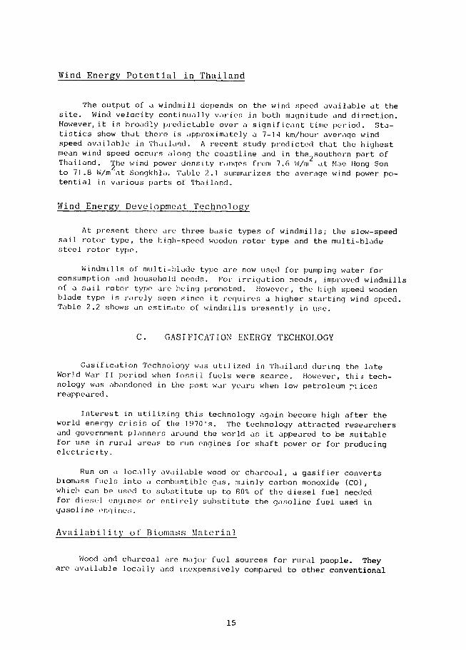
The output of a windmill depends on the wind speed available at the site Wind velocity continually varies in both magnitude and direction However it is broadly predictable over a significant time period Stashytistics show that there is approximately a 7-14 kmhour average wind speed available in Thailand A recent study predicted that the highest mean wind speed occurs along the coastline and in the2 southern part of Thailand 5he wind power density ranges from 76 Wm at Mae Hong Son to 718 Wm at Songkhla Table 21 summarizes the average wind power poshytential in various parts of Thailand
Wind Energy Development Technology
At present there are three basic types of windmills the slow-speed sail rotor type the high-speed wooden rotor type and the multi-blade steel rotor type
Windmills of multi-blade type are now used for pumping water for consumption and household needs For irrigation needs improved windmills of a sail rotor type are being promoted However the high speed wooden blade type is rarely seen since it requires a higher starting wind speed Table 22 shows an estimate of windmills Presently in use
C GASIFICATION ENERGY TECHNOLOGY
Gasification Technology was utilized in Thailand during the late World War II period when fossil fuels were scarce However thi3 techshynology was abandoned in the post war years when low petroleum -iices reappeared
Interest in utilizing this technology again become high after the world energy crisis of the 1970s The technology attracted researchers and government planners around the world as it appeared to be suitable for use in rural areas to run engines for shaft power or for producing elcctricity
Run on atlocally available wood or charcoal a gasifier converts biomass fuels into a combustible gas mainly carbon monoxide (CO) which can be used to substitute up to 80 of the diesel fuel needed for diesel engines or entirely substitute the gasoline fuel used in gasoline engines
Availability of Biomass Material
Wood and charcoal are ma3or fuel sources for rural people They are available locally and inexpensively compared to other conventional
15
Place
Bangkok
Koh Samui
Khon Kaen
Khlong Yai
Chonburi
Chaiyaphum
Chiang Mai
Don Muang
Tak
Korat
Nakorn Sri Thammarat
Nan
Prachin Buri
Phitsanulok
Phrae
Phuket Airport
Mae Sot
Mae Hong Son
Ranong
Loei
Sakhon Nakhon
Suparn Buri
Surat Thani
Nong Kai
Hua Hin
Uttaradit
TABLE 21
AVERAGE WIND FOWER POTENTIAL
Wind Power Wind Power
Potential Place Potential (kwkm2 ) (kwkm2 )
6184 Kanchanaburi 8509
29592 Koh Sichang 19038
5448 Phumipol Dam 6576
8379 Chantaburi 3977
14216 Chum Phon 24125
9515 Chiang Rai 3800
5507 Sap Muang 6561
40970 Trang 20728
10577 Nakhon Phanom 5324
4391 Prachuap Khri Khan 17996
8722 Narathiwat 11943
2122 Pattani 12021
5411 Phetchabun 6184
2010 Phuket 6121
5349 Mukdahan 11020
28968 Mae Sariang 2440
11227 Roi-et 6775
1525 Lop Buri 7537
8163 Lam Pang 3081
5239 Songkhla 32799
9885 Surin 4279
9091 Sattahip 36292
4732 Hat Yai 16972
4099 Aranyaprathet 4360
13120 Udon Thani 2483
1364 Ubon Ratchathani 17372
Source Panich Banterng Boonchai and Kwan (1981)
16
TABLE 22 WINDMILLS USED FOR WATEP PUMPING IN THAILAND
SPrice Nomenclature No in Use Maniacturer P Technical Data(Bht
A Pooular windmilZs3 Isc Bamboo Mat Sail Type 3000 Villager 9500 Blade Diameter 6-8 m
3Local factory Pumping Capacity 46 m hr Total Lift Head 06 m Wind Velocity [3 kmhr
2-4 Wooden Blades Type 3000 Villager 1200 Blade Diameter 6-8 m (Cha Chueng Sao) Local factory Pumping Capacity 90 m3hr
Total Lift Head 09 m Wind Velocity 21 kmhr
Multi-Blade Type (USA) 1500 Thai USA See See Table 31
Table 31
Multi-Blade Type 300 Chonburi Unknown Unknown
B Yew dvetoDed winzamills
Sail Wing Type (NEA) 20 National Energy 12000
Administration Sail Wing Type (KU) 3 Kasetsart 12000 Blade Diameter 4 m
University Pumping Capacity 17 m3hr
Total Lift Head 45 m Wind Velocity i0-12 kmhr
Cycle Wheel Type 2 Songkhla 12000 Blade Diameter 32 m
University Shaft Power 125 w Wind Velocity 3 ms
Multi-Blade Type 8 King Mongkuts 33000 Blade Diameter 3-4 a institute of Piston Diameter 4 m Technology No data test
Sail Wing Type 20 American Volunteer Unknown Designed by Sahores
Savorous Type 10 Several Organiza- Unknown Low efficiency
tions
Augmented Turbine 2 Kamthorn Unknown Sail Wing Data 38 m
Plysummit Turbine Diameter I2 m Height of Turbine 12 m
Pumiing Capacity 04b mmin Total Lift lead 05 m Wind Velocity 10 kmhr
SourceNational Research Council Bangkok(1981)
17
fuels Charcoal is the best fuel source to feed a gasifier However considering the fact that there is a loss in energy of approximately 70 percent in converting wood to charcoal it appears that wood would be the better choice Unfortunately there are few acceptable small wood
gasifiers on the world market today that are able to produce tar free gases suitable for use in an internal combustion engine
Another unfortunate fact is that even though wood fuels seem to be substantial available locally (as3 shown in Table 23) energywise the
quantity of wood (1289 million m ) is roughly comparable to only 1000 million barrels of crude oil or approximately 6 of the total national energy consumption in 1982 Nevertheless wood fuels are presently an
important resourcefirst as a source of cooking fuel for rural people secondly as a resource in the wood industry and third for use by
the country as a natural forest
Therefore if the wood or charcoal gasifier is to be promoted on a
national scale it is essential that the woodlot plantation be implemented where the gasifier is used
Fast growing tree species suitable for Thailands soil and climatic
condition are the Eucalyptus Camaldulesis and the Casuarina Junghuniona Table 24 shows the estimated yield of these tree species
TABLE 23 AREA AND PRODUCTIVITY OF FORESTS IN THAILAND
Prcductivity Growing stock3 Region Area (million ha) (m3ha) Volume (1036 m
North 113 33 599
223Northeast 78 29
Central 47 46 220
77 247South 32
Total 270 48 1289
18
TABLE 24 YIELD OF SELECTED FAST GROWING TREES
Yield Species
(m3hayear)
EucaZyptus camaldulesis (moderate management 5 years old) 18-75
Casuarinajunghuniana (intensive management 5 years rotation) 13-44
Other (poor management 10 years old) 10-15
Present Status of the Technology
Combustible gases from biomass can be produced from a device called a gasifier This device may be classified into three basic types Upshydraft gasifier downdraft gasifier and crossdraft gasifier
In the updraft gasifier the air is taken in through a grate at the bottom of the gasifier and the biomass fuel is fed from the top The direction of air flow is reversed in the case of a downdraft gasifier In the crossdraft gasifier air is introduced through a horizontal nozzle in the wall of the gasifier and the gas is taken out the opposite side The main difference between the updraft and downdraft gasifiers is that more combustible gases are generated in the updraft gasifier and more clean gases are produced in the downdraft gasifier when generating comshybustible gases for an internal combustion engine As stated earlier gasification technology was once abandoned because it was not economical compared with the cheaper fossil fuels during and after the post-war period Also there are many minor problems associated with the use of gasifier engines they require intensive maintenance they are difficult to start they require a skilled operator there is a health hazard if not used properly and no design currently exists for a gasifier that is able to use all types of iomass and charcoal
It is therefore not surprising that many research and development activities in Thailand (as shown in Table 25) are attempting to improve the weakness associated with a gasifier and to demonstrate that it is an economical energy choice
19
TABLE 25 RESEARCH AND DEVELOPMENT ACTIVITIES TN THAILAND
Institute asiferEnd use Status and engine
] Department of Agri- Updraft 5 HlP Charcoal Water pumping Under improvement cultural Technology Gasoline engine since 1980
2 Prince of Songkhla University
Downdraft 5 HP Commercial charcoal Electricity Experimenal plant gasoline engine Rubber tree charcoal operated more than coupled to 2 kWe 500 hr since 1980 generator
Downdraft 35 11P Commercial charcoal Electricity In operation for gasoline engine Rubber tree charcoal aoproximately driving 110 kWe Rubber tree wood 1000 hr generator Coconut shell
Downdraft 24 HP Commercial charcoal Electricity Under performance diesel eneine Rubber tree charcoal driving al0 kWe Rubber tree wood generator
huialongkorn niverityDowndraft 500 We Charcoal Electricity Under construction
Downdraft HP cubed rice straw Water pumping Under construction
Downdraft 14 HP Wood Water pumping Under construction
Fluidized bed Rice Husk deing planned
Downdraft 25 kWe Corn cobswood chips Electricity Under construction
Downdraft -O kWe Rice Husks Electricity Being planned
King ongkuts Updraft Charcoal Water pumping Under improvement Institute of since 1981 Technology (North Bangkok Campus)
5 Departmnr of Downdraft 25 HP Charcoal woud in operation since1ElectricityPublic Works gasoline engine 1982
coupled to [5 kWe generator
6 National Security Downdraft 12 kWe ICharcoal Electricity In operation at Command leadguarera I Kumdogmai villageCin
Udorn rhani province since 198
20
TABLE 25 (CONT)
Institute Gasifier typeand engine
Fuel End use Status
7 Kinistry of Industry Downdraft 12 kWe Charcoal wood Electricity Field test to start
in 1983
8 Kampangphet Provin- Downdraft 3 kWe Charcoal Electricity In operation cial Public Works office
9 Patumwan Technical Institute
Downdraft 16 HP engine coupled to
Charcoal Electricity Under improvement since 1982
generator
Downdraft 12 kWe Charcoal Electricity
10 The Royal Forest Department (RFD)
Downdraft 10 kWe Wood Electricity Under improvement since 1982
11 National Energy Administration (NEA)
Downdraft 5 HP Charcoal wood Water pumping Under performance gasoline engine testing
Downdraft 30 HFP Charcoal wood Electricity Test scheme to gasoline engine start July 1983 coupled to LO kWe generator
21
TABLE 25 (CONT)
Institute Gasoline type Fuel End use Status and engine
12 Private sector Kanjanaburi
Updraft 120 HP Charcoal Passenger boat In operation on the diesel engine River Qai in
Kanjanaburi Province since 1981
Updraft 260 IP Charcoal Rice mill In operation at
diesel engine Amnuaypol mill in Supanburi province since 1981
Updraft Charcoal Electricity In operation
13 Prasathong cinema Updraft Charcoal Electricity In operation since Supanburi 1981
14 Private sector Updraft 260 HP Charcoal ligrite Ice-making In operation since Petchabul diesel engine 1981
driving a compresshysor 150 HP
15 Private sector Updraft 160 HP Rice husk Electricity In operation since Chacherngsao diesel engine 1982
116Srimaharacha Co Downdraft 12 kWe Charcoal wood Electricity Under improvement since 1980
17 VS Factory Downdraft Wood anthracite j Burner Under improvement for commercialization since 1983
Source National Energy Administratlon
22
D BIOGAS ENERGY TECHNOLOGY
Overview
Biogas has been known for decades Sanitary engineers are familiar with the treatment of domestic sewage sludge and organic wastes by methane digestion A methane is a container which keeps organic wastes in such a manner that natural bacterial degradation of the organic matter occurs in the absence of oxygen In other words methane digestion is an anaeroshybic process in which organic wastes are converted to methane gas and carshybon dioxide For animal manures the anaerobic process yields approximateshyly 55-65 percent methane 35-45 percent carbon dioxide and very small amounts of nitrogen hydrogen oxygen and hydrogen sulfide
In anaerobic digestion organic matters are mixed with large populashytions of micro-organisms under the absence of oxygen Initially there is no methane formation Complex organic materials such as fats proteinsand carbohydrates are biologically converted to organic fatty acids byacid-forming bacteria Later on the organic acids are converted to meshythane and carbon dioxide by methane forming bacteria
The gases yielded from the process are commonly known as biogas It is combustible and can be used as a substitute for fossil fuel for lighting cooking gas engines gas refrigerators etc
Availability of Biomass Material for Biogas Generation
Various biomass materials and organic wastes can be used as a raw material for a methane digester At present animal manures are the most popular choice for rural people Other materials can be used but they need to satisfy certain conditions if high energy gas is required For an agricultural country like Thailand these biomass materials are availshyable in excess provided a proper collection is instituted
Status of Technology
Biogas digesters have been utilized by the Sanitation Division of the Health Department in rural areas since 1970 These were primarilyintroduced for public health and welfare reasons as the biogas digester gets rid of undesirable wastes that can cause serious diseases among rural people
Later on the National Energy Administration began an extensive program for the demonstration and promotion of biogas digesters in order to produce combustible gas fertilizer in addition to the environmental and health protection aspect
Several biogas digester designs exist in Thailand at present The Chinese and Indian designs have been modified and adapted to suit Thailands
23
local conditions Several other types of biogas digesters also exist eg the Thai water jar type and the Taiwan rubber bag type
The promotion of biogas utilization as an energy substitute has beshygun recently The campaign is considered to be a joint venture by the National Energy Administration (NEA) and wiveral public and private orshyganizations eg the H-alth Department the Public Welfare Department the Agricultural Extension Department the Co-operative Promotion Departshyment the Community Development Department the Office of Adcelerated Rural Developmentetc
Table 26 shows the number of biogas digesters available in Thailand as compnild bv the NEA in 1984 During 1970-1983 there were more than 4953 niogas digesters in the country Two were community biogas plants for electricity production for a typical sized village in the Northeastern region
TABLE 26 NUMBER OF BIOGAS DIGESTERS IN THAILAND
Year Noof Digesters
1970-1976 207
1977 41
1978 23
1979 151
1980 370
1981 643
1982 1668
1983 1790
Remark incomplete information
24
Biogas utilization can be applied to cooking lighting heating electrical power or mechanical power Some adjustment or adaptation of the energy equipment is needed in order to operate them with a biogas Table 27 indicates the typical rate of biogas consumption for various equipments under normal operating conditions
TABLE 27 BIOGAS CONSUMPTION FOR TYPICAL EQUIPMENT
Item Consumption
3Lighting 25-3 ft per mantle per hour
Cooking 11-16 ft3 per hour per 2-4 in burner 12-15 ft 3 per person per day
Gas Refrigerator 11 ft3 per hour per cubic foot
Gasoline Engine 17 ft3 per bhp per hour
25
CHAPTER 3
BASIC DESIGN OF THE STUDY
BASIC DESIGN OF THE STUDY
In this chapter the system performance the basic design considerashytions plus the operation and maintenance of four types of water pumpingsystems are described These include the solar water pumping system thewind turbine water pumping system the gasifier water pumping system and the bioqas water pumping system
A SOLAR PUMPING SYSTEM
System Performance
The solar water pumping system consists of a number of solar cellsa direct current (DC) motor and a water pump The solar cells convertthe solar energy into an electrical energy this is known as a photovolshytaic system The electricity produced is then used to drive the DC motorand the water pump This water pumping system holds great promise forsmall-scale irrigation and for supplying a community domestic water supply
The key element of the solar module is the silicon solar cell Eachsolar cell has an electrical potential of about one-half volt when exposedto bright sunlight Peak power will be produced at 045 to 048 volts percell The amperage of a cell is dependent on the cells area An assemshybly of these solar cells wired in series makes up a solar module Toproduce the required ampere-hoursday for a water pumping system a numberof modules are assembled on a support structure making array thean with required output
A photovoltaic array consists of several photovoltaic (solar cell)panels which ore arranged in series and parallel according to specificpurposes Each panel converts sunlight to electricity through siliconcells which are approximately 100 mm in diameter and either square ortriangular in shape Each cell produces 25 milliamperes of d rect curshyrent per square centimeter under solara irradiance of I kWm at 25 Celshycius and approximately 05 volts under nominal operating conditions These cells are usually connected in a series or string to build a volshytage up to a required level The cells are sandwiched to form a rectangushylar panel and covered with either glass or clear plastic
An important feature of a solar panel (module) is that it should berugged and capable of resisting ultra-violet radiation thermal cyclingshock moisture penetration etc in order to sustain its performance even under severe operating conditions
29
A solar module is usually rated in terms of Peak Watt i2 e the
power a module can produce at an irradiance of 100 Watts per cm at 25
Celcius
The battery stores the electrical energy which is prcduced through
an electrochemical process In the photovoltaic system a battery can
store excess energy and deliver electricity to load when there is no soshy
lar radiation Therefore the addition of a battery in a system will
facilitate operation guarantee that a system will provide power at any
time and act as a power buffer between an array output and load Howshy
ever several disadvantages are also built-in when using a battery for
example high capital investment and extra control equipment is needed
to regulate the charging operations
Batteries are usually rated in terms of their ampere-hour capacity
Other important specifications include rated voltage operating temperashy
ture self-discharge rate rated current life-cycle size weight and
cost
A motor amp pump set in solar pumping applications has a variety of
combinations For a motor there are choices between a brush or brushshy
less direct current (DC) motor an alternating current (AC) motor with DC
to AC inverter or a motor with a maximum power point tracker For the
pump there is a choice of a centrifugal pump a rotary pump a piston
pump or a submersible pump etc
Today there is no designated motor and pump combination which
would generally be accepted as the best In the selection of a motor and
pump set the following should be considered the water requirement and
head conditions the meshing between the motor and pump set with the solar
cell array the water needs and its duration environmental and operating
conditions etc
Nevertheless experiences to date have lead to the following conclushy
sions
0 For systems up 1 HP a DC motor with a permanent magnet is
generally used
or an
AC motor are most commonly accepted For systems of 1-3 HP a DC motor of a shunt field type
For systems above 3 HP
A maximun power point tracker is an electronic controller used to
mesh the power from a solar array to the load This device may cause some
breakdown during operation Therefore if the system is well designed
the deployment of the controller in the system is unnecessary
When a dynamic head dominates a centrifugal pump is favored while
in other cases batteries or sophisticated controls should be used to reduce
30
useful energy losses from mismatching and
0 The incroduction of batteries or sophisticated controls are exshypensive and require extra maintenance
The pumpmotor should be securely mounted to a foundation that is leshyvel and free from movement in an area clear of materials that could intershyfere with the operation of the upit It should be located as near the source of water as practical to minimize the vertical lift of water to the pump and so that a short suction pipe with a minimum number of fittshyings can be used to keep the pipe friction loss as low as possible
A strainer should be installed at the inlet end of the suction pipe to prevent solids from clogging the pump The selection of the pipe size is dependent on the flow rate
If possible shelter should be provided for the pump and motor unit to protect them from the weather Adequate space around the pump should be provided for service and ventilation when it is running
A typical system efficiency may be set for each component as follows
array cell 11
connection 95
motor 85
pump 50-55
pipe work 95
battery 80 (if used otherwise 100)
impedance mismatch 70-90 (if using an electronic controller 24gt
other miscellaneous 90
Total for system 21-39
The efficiency f a photovoltaic pumping system varies depending on many factors egthe combination of components the efficiency of composhynents operating conditions etc
Basic Design Considerations
In the design of a solar water pumping system the following items should be considered
General requirements
The system should be designed to survive particular local climatic conditions In areas prone to typhoons or hurricanes it may be necessary to provide for the rapid dismantling and removal to safety of the array
e Pumps and motors should be provided with sunshades whenever possishyble but the unit must remain well ventilated if air-cooled
e Materials exposed to solar radiation (such as plastics) should have proven durability
Modules should be individually packed to avoid damage in transit The safety of the contents should not be dependent on receiving special handling treatment
Detailed instructions should be provided in the local language for the correct assembly of the system Also included should be a comshyponents list maintenance and operating instructions and guidance on how to achieve the best output All documents should be written in simple terms and
The need for routine mainterance lubrication and readjustments should be minimized and avoided if possible
Array and module requirements
The array should be manufactured with a lifetime guarantee of at least 5 years against faulty quality with no more than 10 degradation of performance
Small modules (less than a 20 W nominal rating) are preferred
It should be installed either with a laminated glass or an impershyvious and ultra-violet resistant plastic cover
Optimum module cell efficiency should exceed 11
There should be no air gap between the cell encapsulant and the cover glass
It should be equipped with generously sized (brass) terminals with grip screws or with appropriate plug and socket connectors
Array nominal voltage under peak sunlight conditions should be around 50 V higher voltages will not be safe while lower voltages will mean higher currents and larger resistive losses and
e Quality assurance and testing to a satisfactory standard should be specified by the manufacturer Module or array performance should be specified on the basis of tests to a stated international standard The modulearray area to which array efficiency is referred must oe clearly defined
Motor and purp
A DC permanent magnet motor is preferred unless the alternative is shown to be of comparable efficiency
32
0 Full load motor efficiency should exceed 85
Half-load motor efficiency should exceed 75
e Motor bearings and other -omponents should be sized for a life in excess of 10000 hours
e Submersible units are preferred to eliminate suction problems
If the motor is not submersible couplings between the motor and p imp should permit significant motor and pump angular andor parallel msalignment
9 Motor and pump bearings should-be entirely independent except in the case of integral submersible motor-pump units
0 Thermal cut-out is required on the motor unless the motor can sustain continuous stalled conditions with the maximum array current
6 The pumps optimum efficiency should be in excess of 50
The pump should be capable of self-priming in the event of a leakshying footvalve (where fitted)
Impeller material clearances and passages should be suitable for use with water containing suspended silt andor corrosive salts Open impellers are preferred
e Where necessary a suitable strainer for larger particles should be provided and should be sized so as to have a negligible effect on pershyformance while clear
4 Pump should have bearings Jized for 10000 hours of operation and should be supplied with spare seals plus any other consumables to cover that period of operation ball bearings with greased seals are preferred
Pump characteristics should permit stable operation at sub-optimum speeds
The pump should be capable of running dry without serious damageif not a submersible type alternatively a fail-safe method of protection from runnin3 when dry should be provided (with seals designed to suit) and
Pipework and fittings should be correctly optimized for minimum system cost rather than minimum pipework cost all pipework should be supplied with system to length specified for head and site
Specifications for the Installed Solar Pumping Systems
In purchasing solar pumping units for this project the following specifications were given
33
General requirements
0 The systems shall be provided for DC pumping to be used for irrishygation or water supply Each system shall include
- Photovoltaic modules and array support structure
- Required motor and pump set(s)
- One spare motor and pump set
- All necessary control equipment and wiring
- A voltmeter and an ampere meter to m Lsure voltage and current from the solar cell array
- All fixings and auxiliaries necessary for complete construction
- All special tools needed for assembly and maintenance
- Spare parts recommended for three full years of operation (inshycluding motor brushes if applicable) and
- Any other components necessary or recommended in order to proshyvide reliable safe operation andor optimum efficiency
All components except fuses and lamps shall be guaranteed against defects in design workmanship and material for a period of 1 year
Each system shall be designed to operate under the following enshyvironmental conditions
- Ambient air temperature between 0 C - 45 C
- Relative humidity up to 95 at an ambient temperature of 40 C
- Wind speed up to 100 kilometers per hour
- Water source temperature up to 35 C
- Water source containing particles not exceeding 03 mm and
- Annual average daily insolation is 176 MJm2 per day
Each system slall be able to pump water when solar radiation is more than 400 wattsm
The solar cell unit shall be a single crystalline silicon type and the solar module shall be a complete sealed unit consisting of a number 6f solar cells in series or series-parallel combination Solar arrays are a number of solar modules connected in a series or series-pashyrallel qombination and mounted in an array frame
34
9 The solar cell module shall have a conversion efficiency equal o or greater than 8 when measured under standard conditions of 100 mWcm at 25C cell temperature
Electrical termination shall be either screw-type or cable suishytably sealed at the entry to the solar module All terminals shall be electrically isolated from any metal frame or support
The surface of the module shall be tough transparent plastic or toughened glass capable of withstanding without damage any stresses imposed as a result of temperature cycling wind pressure resulting from wind velocity and other environmental changes
The solar array shall be mounted on a flat surface with the range of angle adjustment (the incline angle) variable from 15 to 35 degrees
The array frame material shall resist corrosion when installed in tropical conditions Stainless steel aluminium and hot dipped galvanized miie steel are considered to be satisfactory array frame materials
e All fasteners and associated components shall be compatible with the array frame and solar modules used to avoid corrosion Modules shall be mounted so that they can be removed from the front by one person and all cables and interconnections shall be arranged for easy replacement
Where a number of solar modules are connected in series-parallel combinations the operation of any onp parallel string of modules shall not affect the operation of any other string in the event of (a) failure of a module(s) in a parallel string andor (b) shading of a module(s) in a parallel string Blocking or isolating diodes shall be connected in series with each parallel series of modules
All cables shall be generous in cross-section to limit resistive losses at full power to no more than 5 blocking diodes to result in no more than 2 loss at full power
In this water pumping project 3 units of solar water pumps were installed These included a 4300-watt unit for irrigation purposes a 700-watt unit for domestic water supply and a 300-watt unit for a microshyirrigation system The designs of these solar pumping units were as follows -
The 4300-watt irrigation system
The system was designed for installation at Sukorn Village Chumshyphuang District Nakhon Ratchasima Province latitude 14 58 N longishytude 102 07E elevation of station 188 meters above MSL average ambient temperature 27 C
The nominal maximum power at the standard condition (100 mWcm
at 25 C) of the solar cell shall be at least 4300 watts to assure with
35
2
adequate safety factor a total water discharge of more than 480 m3day at 5 meters head (static suction lift is 3plusmn1 meters)
0 The maximum number of motor and pump sets employed in the systemshall be 5 units (not including the spare set) All units shall be identical
Permanent magnet DCmotor(s) shall be employed with an efficiencyof more than 75 of their design rating The pump(s) shall be of the self-priming centrifugal type
The solar array frame shall be designed so that it is suitable to install on a concrete slab with the lower edge of the frai 15 meters above the ground
The system shall include an automatic cut-out with automatic reset to protect the system from excessive temperature voltage or current and
The system shall include monitoringcontrol box(es) designed fortropical conditions and high ambient temperatures for the following items
- Maximum power controller or maximum power point tracker if employed
- Automatic cut-out with automatic reset if employed and
- A voltmeter and ampere meter to measure voltage and current from the solar cell array
The 700-watt water supply system
The system is designed for installation at Ban Tha Yiam (Village1) Non Hom Sakon Nakhon Province latitude 17degN longitude 104E average ambient temperature 27C
The well characteristics are as follows
- Draw-down depth 95 m for static water level
- Maximum P-i inissible pumping rate 094 liLerssec
- Chlorine is less than 30 ppm
- Iron is less than 25 ppm
- pH is 78
- Total hardness is 142 ppm as CaCO3
- Total dissolved solid is 248 ppm
- Static water level is 8 m below ground level and
- Depth of casing is 24 meters
36
2 The nominal maximum power at the standard condition (100 mWcm
at 25C) of the solar cells shall be at least 700 watts to assure with a~equate safety factors a total system water discharge of more than 10 m day at 215 meters total dynamic head
A permanent magnet DC motor shall be employed with an efficiency of more than 75 of its design rating The pump shall be a centrifugal pump or a suitable substitute recommended by the contractor If a piston pump is employed a maximum power controller shall be required
The solar array frame shall be designed so that it is suitable for installation on a concrete slab with the lower edge of the frame 15 m above the ground
The system shall include an automatic cut-out with automatic reset to protect the system from excessive temperatures voltage or current
The system shall include monitoring control box(es) designed for tropical conditions and high ambient temperatures for the following items
- Maximum power controller if employed
- Automatic cut-out with automatic reset if employed
- Voltmeter and ampere meter to measure voltage and current from the solar cell array
All necessary piping and connections shall be provided Pipe drop to the well shall be approximately 12 meters
The 300-watt rnicro-irrigation sgstem
e The nominal maximum power at the standard condition (100 mWcm2
at 25C) of the solar cell modules shall be at least 300 watts to3 assure with adequate safety factors a water discharge of more than 50 m day at 3 m head
The system shall not employ a battery
A DC motor shall be employed and be of the permanent magnet typeits efficiency shall be more than 75 at the design condition The pumpshall be a self priming centrifugal pump or a suitable substitute recomshymended by the contractor and
e The system shall include a strainer a flexible pipe or hose of not less than 3 m in length for suction and a flexible pipe or hose of not less than 5 m in length for discharge
37
B WIND TURBINE PUMPING SYSTEM
System Performance
The wind turbine is a device which converts wind energy into mechanical energy This mechanical energy is then used to drive a water pump A positive displacement pump is used in this installation This system was used for farm irrigation several hundred years age
Technical Design
For locally made windmills in Thailand very little information on technical performance is available This is partly due to the fact that there is no acceptable standard testing precedure Some typical windmill performance data are taken from manufacturers information sheets
Thai USA windmills
These are steel multiblade windmills 8-20 ft in diameter The Thai USA windmill has 20-45 blades with a piston pump 25-18 inches in diameter It is claimed that these windmills can lift water at verylow speeds Table 31 shows typical performance data for these windmills manufactured at the Thai USA Industrial Factory Bangkok
Vita windmill
The Vita windmill is designed for irrigation where a large volume of water is needed at low head The rotor of this type of windmill is approximately 6 m in diameter with 8 bamboo or laminated wood blades A modified rotary chain ladder pump with a 4-10 in diameter is used Power extracted from the wind stream is transmitted to a pump by a 4shyinch industrial belt
The VITA windmill was recently developed in Thailand by Volunteers in Technical Assistance Asia field office (VITA Asia field office)At jLiesent they are being manufactured and marketed by the Windmill Pump Co Ltd Thailand The cost of one complete system is 45000shy78000 Baht
The VITA windmill V-8 type has a maximum pumping rate of 4000 liters per minute with a starting wind speed of 3 meters per second and a maximum design wind speed of 140 kilometers per hour The manufacturer claims that the unit has a 15 year working lfe (75000 hours) with a water cost of approximately 002 Baht per m of water pumped when being operated at 33 ms and one meter lift
The NEA 8ail type windmill
The National Energy Administration (NEA) has developed a low cost windmill which is easily fabricated from locally available materials
38
tABLE 31 tECHNICAL DATA OF THAI USA WINDMILL
Blade Dia Height No of Blade Piston Dia Water pumped Wind Velocity Price Note (ft) (in) (in) (Ithr) (kmhr) (Baht)
8 15 20 25 1200 10 28000 1) Price effective
10 15 30 3 2000 10 35000 Sept 27 1982
12 15 30 45 2500 10 51000 2) Excluding
14 15 30 6 6000 10 64000 installation
14 15 30 10 12000 10 71500 3) Installation cos
16 15 45 12 16000 10 93000 charge is3500-4500 Baht
18 15 45 16 20000 10 100000 depending on
20 15 45 18 24000 10 120000 distance
39
The unit is a typical old-fashioned sail type windmill However several improvements have been made The NEA Sail Type windmill (model WE 002) has 8 sail wings attached to 540 m long wooden spars 2Each sail wing is made of a plastic coated fabric within area of 24 m The rotor diashymeter is 6 meters with a steel shaft for mechanical power transmission The piston pump is a single stroke type with a displacement of 125 mm The piston rod is 76 mm in diameter and is made with a thick PVC piston bore and a camel leather piston ring
Specifications of the Installed Windmills
In this study three windmills were installed in Ban Samoh Tambon Ta-tong Amphue Raman Yala Province These included two multiblade windshymills and a VITA type (V-20B) windmill
The multi-biade windmill
Each blade is made of a galvanized steel sheet fixed on the L-shaped steel frame The diameter of the wind blade is 305 m (10 ft) This wind blade is installed on a steel support at an elevation of 12 m above ground level
The water pumping system is a single stoke type with a piston diashymeter of 75 cm (3 inches) The stoke length is 75 cm (3 inches) and
The water well is a dug well with the water table 450 m below ground level
The V-20B type vita windmill
There are 25 blades made of bamboo and fixed to an L-shaped steel frame The center of the blades is approximately 75 m above ground level
Water pumping is accomplished by using a PVC ladder pump with a 6-inch diameter and
This windmill will provide high starting torgue and low speed which is suitable for the ladder pump The blades can start the pump with a wind speed of 4 ms and will continue rotating as long as the wind speed does not drop below 2 ms
C GASIFIER PUMPING SYSTEM
The gasifier pumping system consists of a reactor a feeding bin a gas cleaner and cooler a mixing box an int ial combustion engine and pump set (Figure 31)
40
biomass
colder gas hoth
dirty gas
gReactor c s Cleaner bo mn xi (CO) InternalH W mand Cooler e B o Combustion Pu
4Engine
ash fly-ash
soot
tar
moisture
heat
FIGURE 31 BLOCK DIAGRAM OF GASIFIER PUMPING SYSTEM
Combustible gas is extracted from wood or other biomass by burningthe material with limited air This is referred to as gasification The gas produced consists mostly of carbon monoxide (CO) hydrogen (H_)methane (CH ) and the incombustible components carbon dioxide amp O) and nitrogen (N )
The reactor is the main gasifier component where the gasification process takes place Solid biomass (usually charcoal or wood chips) is fed in from the top ash i collected and removed at the bottom and the gas produced leaves through a side outlet This gas is hot and contains impuriLes The gas clearar and cooler removes the impurities to make it clean and lowers the te2mperature of the gas to make it denser so that more of it will enter the engine to give a greater power output
The gasifier reactor may be classified into three types ie crossshyflow updraft and downdraft The name describes the airflow direction from the entry of air to the exit of the produced gas The two LItter types are generally used The updraft reactor produces a gas with a slightly higher energy content while the downdraft reactor produces a cleaner gas
The gas cleaner removes the impurities from the gas The three methods used the cyclone separator gas scrubber and the impingementfilter The cyclone separator removes suspended solid particles in the gas such as soot and fly ash by centrifugal force The scrubber removes the condensable solid particles The impingement filter collects impurishyties as gas passes through it
41
The gas cooling method used for stationary application is the watershycooling type This method is generally used with a gas scrubber and is accomplished by having water falling down thru cascading panels as the gas rising up
The mixing box of the Rasifier system is located adjacent to the carshyburetor and is composed of pipings with two valves connected to the acshyceleration pedal One valve controls air flow while the other controls the flow of the gas
Technical Design
The special requirements for the gasifier pumping system to be inshystailed are as follows shy
0 The gasifier shall be a downdraft type and shall accept hard fuel approximately sized in cubes 05 to 3 inches in dimension and with moisshyture content up to 30 wet basis Eucalyptus cwnaZduZess is considered as a fuel wood
The gasifier shall be able to operate continuously for at least 4 hours without an interruption of gas supply
The gasifier system shall have a feature for explosion control and for detection of carbon monoxide leakage
Thp gasifier shall be mounted on a trailer so that it can be easily transported and shall have a basic instrumentation package for monitoring temperature and pressure
A flare stack shall be provided to dispose of excess
3 The calorific value of the gas produced shall be higher than 120 Btuft
The engine may be either a diesel or gasoline-type If diesel the engine must be capable of running on diesel fuel andor producer gas (Diesel fuel consumption shall not be over 20 of the total energy conshysumption) The engine shall deliver a rated power of not more than 30 kW
The engine cooling system shall be either an air-cooled or watershycooled type If water-cooled the system shall be capable of utilizing water being delivered from the pump
Additional gas clean-up End cooling equipment (scrubbers and condensers) sufficient to provide reliable engine operation should be included
Pumps shall be of the propeller self-priming centrifugal type or other suitable substitute
Coupling between pump and engine shall be a direct type or other suitable substitute
42
0 The pump shall provide a water discharge of not less than 250its the static suction lift shall be up to 3 m while the designed totaldynamic head is 5 m and
Auxiliary parts shall include two strainers for single suctionpumps or three strainers for double suction puptps The size of thestrainer shall be approximately 15 times the diameter of the suction portSuitable reducers shall be included
Details of the Purchased Unit
The following are the details of the North American gasifier purchasedby NEA
Capacitu
Gasifier output - 20 kWe continuous - 30 kWe intermittent
Operating limits - 5 kWe minimum continuous - 20 kWe maximum continuous
Load following - less than 1 second response to a 25 load increase
Engine - Ford Model 23L Continuous Duty 38 HP - The rating for low Btu gas 60 of rated horsepower
Fuel
o Optimum size - 1-inch cubic minimum - 4-inch cubic maximum
Moisture content - 15 optimum - 30 maximum
Gasifier performance - fuel consumption increases with an increase in moisture content- decreases in performance with fuel under and over size - design performance
20 kWe 25 shaft horsepower 2000 rpm50 lbs wood per hour
43
0 Fuel processing - harvest wood source - process while high in moisture content - store and dry - fuel reactor at less than 30 moisture content - recommended fuel processing equipment
Kopo (see attached data)
Gasifier power generation system
Operation - Start up
empty ash and water check engine oil and water
light flare pilot fuel reactor check valve positions ignite fuel in reactor
start electric blower purge cooling and cleaning system
start engine connect load
estimated total time20-30 minutes
- Shut down
engine ignition off
set valves go home estimated time1 minute
Fuel charge - one charge 50 lbs (dry wt) - estimated total loading time 1 to 2 minutes - frequency once every 2 hrs at kWe
- recharging can be done while running reactor
Effect of running out of fuel
- Btu level of gas to the engine will drop and the engine will
no longer follow the load possibly stall
Gasifier maintenance
- lubricate grate shaft bearing once a month (grease gun)
- remove ash and char daily (small hand trowel) - remove excess water daily from overflow tank
- normal English automotive tools plus pipe wrenches are used for all normal maintenance on the gasifier
- skill required for operation no special skills
- reactor shut down during above maintenance
Enginepump maintenance
- all normal maintenance and tools for engines and pumps
- no cleaning required for tars or soot
- skills required include those for a competent engine operator
with knowledge of pump operation
44
Environmental considerations - Solid wastes are inert and can be placed in a land fill or used
as a soil amendment Estimated solid waste production per day 1375 lbs
- liquid wastes are composed of water condensates with small fractions of black carbon soot and ash These may be put in a domestic sewer with no shock loading effect on any convenshytional sewage system No tars are produced in the gaifier A land treatment system with special consideration for temperashyture extremes should be used if no other system is available North American Gasifier Corporation is available for consulting on waste treatment
0 Heat loss rates (estimated) - reactor 30000 Btuhr - heat exchanger 10000 Btuhr - engine cooling jacket 60000 Btuhr - engine exhaust 35000 Btuhr
Gas components - H = 5
- CO 2 = 3
0 = 1
- CH = 1
- N = 62
- CO = 28
- moisture content saturated at ambient - tar content none
Uses - This is a new product design which eliminates tar production
Designed specifically for Third World application where technical expertise is at a minimum and operational conditions are the most severe
Manual
All manuals and instructions will be included with the gasifier when shipped
Price
Reactor blower scrubber holding US$ 1356760 tank heat exchanger demister flare pilot all piping and valves engine modifications and special tools
Enginepump ITT Marlow model4D2 to US$ 454750 include heat exchanger for engine water jacket trailer with engine and gasishyfier mounted
45
Total FOB US $ 1811510 Freight amp Insurance US $ 311590
Total US $ 2123100
D BIOGAS PUMPING SYSTEM
System Performance
This system consists of a digester tank an internal combustion enshy
gine and a pump The biogas produced from the digester will be used as
a fuel for the engine to drive the water pump
Biogas which is composed mainly of methane (CH4 ) and carbon dioxide (CO2 ) is a by-product of anaerobic fermentation process Anaerobic bacshy
teria breaks down organic matter from complex forms into simple forms of
organic acids These acids are then further converted biochemically to methane carbon dioxide and new bacteria cells
Animal manure is usually utilized as a raw material for biogas proshyduction Human excreta and some vegetations can also be used The value of the carbon-nitrogen ratio (CN) is considered an important factor that characterizes the property of these raw materials The value should not
exceed 351 (Singh 1972)
Technical Design
Although a large number of biogas plants have been installed in various parts of the world the criteria for both the design and operation of this process are not yet satisfactorily established This is because of the
variety of raw materials and other environmental factors which affect the fermentation process in the reactor In this section general criteria which should be considered in the design are presented (Pitak 1978)
Loading rate
Loading rate can be defined in various terms such as hydraulic loadshying which is controlled by influent flow rate and organic loadings which
use organic matters input to the system (termed as BOD or COD) as a conshytroller Another parameter solid loading employs the amount of influent volatile solids in controlling the unit function
The conventional loading rates are the ones mostly employed and are
a very important parametir in anaerobic digestion The volatile solid (VS) loading rates for biogas units can be generally divided into 2 categories
1 Conventional VS loading and
2 High rate VS loading
46
The conventional loading rates are the ones usually employed in sewshyage sludge digestion while the high rate loading rates are adopted only in certain biogas plants Some advantages of the high rate biogas plants include minimizing the digester volume and a reduction of the high orshyganic materials less water dilution required and consequently less liquid effluent for final disposal However excessive VS loading in a biogas plant could result in still effluent slurry and an accumulation of ammonia in the system which is inhibitory to the methanogenic bacteria
A summary of biogas VS loadings as reported by various investigators is presented in Table 32
TABLE 32 VOLATILE SOLID LOADING RATES USED IN VARIOUS BIOGAS PLANTS
(AFTER PYLE 1976)
Digestgr Size Loading gate Faeces Type (m-) (kg VSm day) Reference
15 155 Pig PYLE (1976)
0015 048-32 Pig HOBSON and SHAW (1973)
28 06 Cow PYLE (1976)
1850 24 Pig LAPP et al (1975)
55 08 Pig CHUNG et al (1975)
The VS loading rate is theoretically related to the rate and quantity of gas production higher loadings will result in more gas production From their intensive digestion study using pig manure as the food in a 15shyliter digester HOBSON and3SHAW (1973) found that the gas production for a loading of 006 lb VSftday was 35 Itday and tqis production inshycreased to 118 1tday with a loading of 02 lb VSftday However furshyther increases in VS loading could possibly lead to a failure of the biogas system
47
Digester detention time and feed dilution ratio
The detention time is the parameter used to control the flow of raw materials feeding into the diqester or the time available for the anaeroshybic bacteria to metabolize the waste The detention time for a continuous no sludge recycle biogas plant is equal to its hydraulic detention time hence its relationship with the feed dilution ritio The digester detenshytion time directly affects the concentration of organic matter and the conshytent of the manure slurry in the influent The higher the dtention time the more concentrated and condensed the sulrry of raw materials being fed which in turn can cause insufficient metabolism at high solids content ie more than 10 solids (TAIGANIDES et al 1963)
The use of a feed dilution ratio as a design patameter for the biogas process in the rural areas is obviously more convenient than using the term digester detention time However the latter is utilized more frequently in mathematical modelling of any biological processes Table 33 shows various detention times and feed dilution ratios of biogas plants with successful operation
TABLE 33 THE OPERATING DETENTION TIME AND DILUTION RATIO
(AFTER PYLE 1976)
Dilution Ratio Manure Type Detention Time DilurenWatio References
NanureWater
Cow 25-30 1 1 PATEL (1971)
Poultry 3-10 1 2 PATEL (1971)
Pig 6-16 1 1 CHUNG et al (1975)
Cow 30-40 1 1 SINGH (1972)
48
Feed composition
The anaerobic process is dependent upon anaerobic bacteria whichrequires nitrogen phosphorus and other nutrients at trace quantitiesfor their growth Each animal munure posses different CN ratios in which if a proper portion of them are mixed (ie CN ratio = 201 to 301) maximum gas production can be obtained (Singh 1972)
Basic factor for digester sizing
Biogas plants are used for various purposes and there are many proshycedures in plants operation There are several basic types of digestersand each has its own advantages and drawbacks Digesters can be divided into batch type or continuous type depending upon the flow system orspecified as fixed cover type or moving gas holder type However the two important basic factors that are used in designing any biogas plants are quantity of gas production required and availability of raw material
Quantity of Gas Production Required
The gas production required can be estimated according to the periodof gas usage and number of people utilizing the gas The gas consumptiondata as estimated by SINGH (1972) is shown in Table 34
Besides cooking and lighting biogas can also be used for refrigerashytors with the rate of consumption in literhr Nevertheless the gas
TABLE 34 METHANE GAS CONSUMPTION FOR VARIOUS GAS FACILITIES
Application Specification Gas Consumptionlthr
Gas Cooking 5 cm dia Burner 3256
10 cm dia Burner 4672
15 cm dia Burner 6371
Gas Lighting for one person 3540
1 Mantle Lamp 708
2 Mantle Lamp 1416
3 Mantle Lamp 1700
49
requirements for different families will vary slightly depending on the design of the appliances the methane content and the gas delivery presshysure The population equivalent will specify the gas usage for that fashymily Therefore the total gas consumption could be roughly calculated from Table 34 as stated previously This amount of gas consumption can be used as a basis for digester sizing design
Availability of Raw Materials
The quantity of raw materials used for a biogas plant must be adequate for the plant requirements and their characteristics should be suitable for plant operation The gas yield from the raw materials varies with the type of manure and its water content The amount of manure available can be estimated by a head count or from the weight of the animal The amount of manure that can be expected from different types of animals is shown in Table 35 (BARGER 1976)
The availability of raw materials also depends upon the mode of mashynure collection and livestock conditioi The confinement of livestock is not always possible nor desirable because crowded livestock are likely to contact diseases Actually about 90 of the manure produced by large animals can be collected and 60 for poultry in good confinement with bedding BARGER (1976) estimated that 50 of the manure would be lost during grazing From this calculation the amount of manure could be roughly estimated from Table 35 and multiplied by the collecting corshyrection factor Thus the roughly available volatile solids could be known and the gas yield from these manures could be estimated
TABLE 35 WEIGHT OF EXCRETA PRODUCED PER DAY BY DIFFERENT ANIMALS
Animals kg FaecesHead Live Weight kg FaecesDay kg Faeces100 (kg) kg Live Weight
Cow Buffalo 3-10 454 236 52
Horse 525 586 163 42
Pig 28-37 73 34 47
Sheep 30 14 45
Poultry 012-025 23 011 0047
50
Sizing the digester
Digester sizing can be generally determined from the two aforemenshytioned basic factors Three methods in which digesters can be sized inshyclude
1 By selecting a fixed detention time and the total daily volume of influent is known
2 By having a fixed volume for every population equivalent in the waste
3 By setting a fixed loading of volatile solids per volume of digester
A combination of methods 1 and 3 seems to be efficient in designing a digester size With the fixed loading determined the capacity of the digester could be calculated by using total weight of the ifluent volatile solids divided by fixed volatile solid loading Hence
Volume of Digester Total weight of VS(kg VSd)
Loading rate (kg VSm3day)
The selected detention tims will indicate the volume of the influent feeding into the digester (as m day) which is the dilution factor required for that manure
Details of the Snecified Biogas Pumping System
The following are details of the biogas pumping system specified in this study
Slurry mixing trough
The slurry mixing trough will be 006 m high300 m long and 120 m wide There is a steel pipe 030 m in diameter connecting this mixing trough to the distribution channel The surface of the walls and the bottom of the mixing trough must be smooth and non-corrosive The foundashytion of the trough must be adequately stable
Distribution channel
The distribution channel will be 050 wide 1130 m long with a 5 slope The bottom of the channel must be smooth so that the mixed slurry can flow to the digestion tanks steadily
Digestion tanks
There will be three cylindrical digestion tanks with stainless steel covers Each tank will be 330 m in diameter
51
Engine and pump
The engine used for this biogas pumping system is a benzene engine with a 10 HP capacity
The water pump is a self-priminq centrifugal pump with a discharge rate of 200 Itmin and with a lifting head of 25 m and
e The engine and the pump will be installed on the same base connected with a belt drive
52
CHAPTER 4
FIELD EXPERIMENTS
FIELD EXPERIMENTS
In this study only two types of water pumping systems were installedie the solar water pumpir~g system and the wind turbine water pumpingsystem In this chapter the results obtained from field experimentsare presented with an aim of demonstrating and determining the performancecharacteristics and overall efficiency of each unit
A SITE SELECTION
Criteria for Site Selection
In selecting the site for water pumping installatki the followingcriteria were used
0 There exists a source of adequate water quality and quantityall year round
The demand of water is -h throughout the year
The service road to the site is in good condition so that installashytion operation and maintenance can be undertaken with little difficulty
There is no electricity distribution network in the area and
The villagers are willing to cooperate with the responsible officialsin the installation operation and maintenance of the project
Selected Sites for Solar Water Pumping Installation
The 4300-watt irrigation system was installed at Ban Sukorn TambonChum Puang Amphoe Chum Puang Nakhon Ratchasima Province This villageis located approximately 90 km southeast of the city of Nakhon Ratchasima The total area of this village i 6265 rai (10024 km 2) The area hasa gentle slope from the northwestern part to the southern and southeastern parts of the village Most of the area is cultivated for growing paddyrice There is a stream named Lcm Pradok in the southeastern sectionof Ban Sukorn A storage weir creates a reservoir covering a total areaof 1446 rai (2314 km2) with a storage capacity of 8 million M 3
Thisstorage reservoir is called Ang Pradok (Pradok Reservoir) The 4300shywatt solar water pump was installed to pump water from this reservoir to irrigate the Ban Sukorn area
55
The 700-watt solar pump was installed at Ban Tha Yiam Tambon Non
Hom Amphoe Muang Sakon Nakhon Province The village area is flat
consisting of agricultural lands and forest areas This pumping system
was installed to pump water from groundwater wells for domestic use by
57 households in this area
Selected Sites for Wind Turbine Pumping Installation
Three windmills were installed to pump water from a storage pond
and a shallow well for agricultural purposes in Ban Samoh village Tambon
Ta-tong Amphoe Raman Yala Province This village is situated approxi-The total village areamately 21 km to the east of the city of Yala
About 60 percent of the area is utilized foris 5060 rai (81 km2) agricultural lands The main crops cultivated are rice rubber vegetables
and some upland crops
B SOCIO-ECONOMIC CHARACTERISTICS OF BAN SUKORN
TAMBON CHUM PUANG
In this section the results obtained from the socio-economic study
of Ban Sukorn Tambon Chum Puang Amphoe Chum Puang Nakhon Ratchasima
are summarized The study was undertaken bu the survey group of the
Energy Economics Division NEA The field survey was conducted during
22 June 1983-21 July 1983 Altogether 56 households (from a total of
115 village households) were randomly selected for questionnaire intershy
viewing
Location and Topography
Ban Sukorn is situated approximately 90 km southeast of the city
of Nakhon Ratchasima The village area covers approximately 6265 rai
of which 1425 rai is public land The topography of the area is characshy
terized by a gertle slope extending from the northwestern part to the
southeastern part of the village There is a stream named Lam Pradok
which flows through the southeastern part of the area A weir with a
sluice gate is located on this stream This weir has created a storage
reservoir with a surface area of 1446 rai and with a storage capacity
of 8 million M 3 The impounded water has been used for irrigation and
domestic consumption
56
Village Characteristics
In all there are 112 households in Ban Sukorn (June 1983) These households are separated into 3 groups namely Ban Sukorn Group Ban Pradok Group and Ban Ta Lum Tong Group Ban Sukorn Group is the largest with 81 households situated in the northeastern part of the area Ban Pradok Group with 26 households is situated approximately 350 m to the west of Ban Sukorn Group approximately 500-600 m from these two groups
Houses in Ban Sukorn are mostly one story structures with an elevatedfloor and a galvanized steel roof These houses are normally located close to the service roads in the village There are three main roads connecting Ban Sukorn and the civic centers of Amphoe Pimai Amphoe Chum Puang and Amphoe Pratai The road connecting Ban Sukorn and Amphoe Pimai is approximately 32 km in total length This is a lateritic road Most of the villagers (85) use this route in travelling to the town The second route from Ban Sukorn to Amphoe Chum Puang is a dirt road which becomes muddy during the rainy season Only 14 of the villagers use this route in travelling to Amphoe Chum Puang to buy household goodsand agricultural input The total length is approximately 7 km The third routu from Ban Sukorn to Amphoe Pratai is also a dirt road approxishymately 12 km in total length The condition of this road is rather poor and the villagers use this route only when necessary
During the rainy season normally from September to November travel along these access roads is not possible During this period villagerstravel by boat along the Pradok stream and the Nam Mun River to AmphoeChum Puang approximately 16 km in total distance
There is one primary school in the village which offers classes to the Prathom-6 level Besides the school there is one Buddhist templenamed Wat Mongkolrasbamrung Both school and temple are located within the Ban Pradok area
Population and Households
There are a total of 112 households with 646 residents in Ban SukornVillage The numbers of male and female residents are 277 and 369 resshypectively On the average each household has 58 members Most of the villagers (58 percent) are between 5-25 years old
57
Education
Approximately 24 percent of the villagers are in school Most attend the primary school (P1-P6) level Another 56 percent have finished studyshying and the remaining 20 percent have never attended school For those who have completed their studies most (98) finished the primary school level (P6) For those who have never attended a school 52 percent are too young(0-5 years old) and 35 percent are older than 46 years
Occupation
Most parts of Ban Sukorn area are flat and there is a storage reservoir located close to the village Therefore most of the villagers list agriculture as their main occupation Besides agriculture some of the villagers work as hired laborers and some work as traders (Table 41)
TABLE 41 MAIN OCCUPATION OF HOUSEHOLD HEADS
Occupation Farming Hired Trading Others Laborer
Percent of Sampled 8750 536 357 357
Household Heads
Besides the above mentioned main occupations approximately 6429 percent of the sampled household heads also engage in subsidiary occupations The most popular subsidiary occupation is pot molding Others earn additional money from vegetables or other crops or from other occupations (Table 42)
Labor Force
Most of the labor force is engaged in farming There are four periods which require intensive labor ie
a June-July when the farmers cultivate their paddy field some also harvest their dry land rice
58
TABLE 42 SUBSIDIARY OCCUPATION OF HOUSEHOLD HEADS
Percent of Sampled
Household Heads
Subsidiary Occupation
wo subsidiary Occupation
with sub-sidiary occupation
Paddy growing
Vegetable growing
Hired laborer
Pot Trading Molding Others
3571 6429 1110 1667 556 556 4444 1667
0 August-October when most farmers do their farm work from the morning till the evening
December-February when the farmers harvest their crops They work
very hard from 500 AM until 1000 PM and
0 March-May when the farmers start cultivating dry land rice
Hired laborers are primarily needed during the harvesting period from January to February
During the March-June period when the farmers have finished harvesting their crops and the school is closed most households engage in their subsidiary occupation for additional household income
Land Use and Land Holding
Most parts of the village area are used for growing paddy rice This land use accounts for approximately 3643 rai per household Howshyever as much as 627 rai per household is left uncultivated The remainshying lands are used for residential purposes growing other crops and orchards (Table 43)
With regard to land holding status these are four types ie owner rental rent-free and athers (Table 43)
59
TABLE 43 LAND USE AND LAND HOLDINGS
RaiHousehold
Type of Area Type of Land Use
Land (rai) residen- orchard upland Paddy abandonedHrain tial crop rice Holding
Owner 3888 094 028 052 3100 614
Tenant 278 - - 015 263 shy
Rent-free 194 001 005 - 175 013
Others 105 - - - 105 -
Total 4465 095 033 067 3643 627
Percent 10000 214 074 149 8159 1404
Agriculture
The Ban Sukorn village area is mostly flat land The area utilized for agricultural purposes covers approximately 2005 rai The main crop grown is paddy rice which can be further classified as wet land rice and dry land rice Besides paddy cassava and vegetables are also grown in this area
Wet land rice
Wet land rice is cultivated in the area surrounding the village Most of the cultivation is of a rain-fed type Cultivation starts at the beginshyning off the rainy season which is around mid-June and the rice will be harshyvested in December-January The yield depends on the amount and periods of rainfall during the year In a draught year the yield is low and the harvested rice will be kept for household consumption only In a year with adequate rainfall the yield will be high and the excess rice will be sold to merchants in the town
During periods of heavy rainfall the paddy fields located close to the Pradok Reservoir will be flooded and damaged The variation in water levels in the Pradok Reservoir relies on the water level in the Nam Mun River
60
Dry land rice
Approximately 36 percent of the total households engage in dry land rice growing However the cultivated area is rather small with an average of only 28 rai per household The dry land rice is grown after the wet land rice is harvested Most of the dry land rice fields are lccated close to the Pradok Reservoir where water is pumped for irrigation
Cassava
Cassava is also grown but only in a small quantity Cassava growing requires less time and effort than paddy rice and other crops The growing period is about 9-12 months
Vegetables
Vegetables are primarily grown for household consumption with the exception of cucumbers which are sold to nearby villages for additional household income
Agricultural production
As previously mentioned agriculture in the Ban Sukorn area is mostly a rain-fed type Therefore production is based on the amount of rainfall each ear
The average yield of wet land rice is approximately 7520 kg per houseshyhold which costs about 19900 Baht (US$ 86522) About 48 percent of the production is used for household consumption 47 percent is sold and the other 5 percent is used to pay off debts
The production of cassava totals approximately per rai All of this production is sold to a merchant The annual income from cassava is approshyximately 198 Baht (US$ 861) per household
Table 44 summarize the average productions and incomes derived from wet land rice dry land rice and cassava in Ban Sukorn village
TABLE 44 AGRICULTURAL PRODUCTIONS AND INCOMES IN BAN SUKORN VILLAGE
Cultivated Production Sale Crop Area (rai Household Paid
household) kgrai kghouse- Consumption for amount cost
hold (kg) Dept(kg) (kg) ( )
Wet land rice 3580 210 7520 3525 403 3592 9483
Dry lana rice 099 305 302 184 7 11 296
Cassava 018 1850 333 - - 333 198
61
Agricultural input
Table 45 ummarizes various items o agricultural input for wet land rice dry land rice and cassava growing in the Ban Sukorn area The major expenses are for fertilizer and labor In all the total expenses for wet land rice dry land rice and cassava growing are 3561 Baht (US$ 15483) 436 Baht (1896) and 42 Baht (US$ 183) per household respectively
TABLE 45 AGRICULTURAL INPUT FOR VARIOUS TYPES OF CROPS GROWN IN
BAN SUKORN VILLAGE
Input (Bahtrai) Overall Expense
Crop s IBahthouse-Seed Pesti- Ferti- Labor Fuel Others Bahtrai hold
cide lizer force
Wet land rice 015 251 4724 4381 425 152 9947 356057
Dry land rice 270 2550 16045 25351 - 270 43946 43564
Cassava - - - 23300 - 23300 4161
Household Economics
Household income
Besides the income from selling agricultural products additional income can be gained from other occupations such as laborer household industries animal raising and trading The annual income derived from these occupations are shown in Table 46 In all the annual income per household is approximately 16609 Baht (US$ 72213) in addition to the income gained from farming
62
TABLE 46 ANNUAL INCOMES FROM OTHER OCCUPATIONS
Annual Income Occupation (Bahthousehold)
Laborer 819068
Household industries 236114
Trading 48036
Animal raising 488571
Land renting 38723
Vegetables 30357
Total 1660869
Household expenditure
Table 47 summarizes the annual expenditures per household in Ban-Sukorn village The largest expenditure is for food and clothing which is considered as a regular expense This costs each household an averageof 6836 Baht (US$ 29722) per year The irregular expenses include repaizs participation in social activities etc The investment item is mainly for agriculcural equiDment and for household industries In total the average annual expenditure is approximately 24100 Baht (US$ 104783) per household
Indebtedness
Approximately 875 percent of the households in Ban Sukorn are indebted primarily for agricultural inputs The main source of loans are relatives neighbors and the Bank for Agriculture and Cooperatives On the average the debt per household is 3690 Baht (US$ 16043)
63
TABLE 47 HOUSEHOLD EXPENDITURES
Annual Expense Item (Bahthousehold)
Regulaz (foodclothesetc) 683616
Irregular (repairs etc) 538761
Investment 381172
Agricultural Inputs 403772
Fuel 153337
Others 249371
Total 2410029
Water Demand
Water usage in Ban Sukorn village is mainly for agriculture and domestic consumption The wet land rice cultivation is based on rain water only From the interviews77 percent of the sampled households reported that there was adequate water for wet land rice cultivation whereas the other 23 percent reported there was not enough water
For dry and rice growing most of the cultivated area is locatedclose to the rcadok Resezvoir where water is pumped for irrigation About 79 percent of the households engaged in dry land rice growing reportedthat there was adequate water while the other 21 percent gave a negative answer
For cassava and other field crops cultivation is entirely based on rain water For vegetables the water used in growing is pumped from the Pradok Reservoir or other dug wells in the village Most of the households engaged in growing crops reported there was adequate water
The main source of drinking water is rain water which is kept ilindividualstorage tanks Some households also use water from the dug wells while the others use the reservoir water On the average the demand of drinkingwater is approximately 33 liters per household per day and the demand for other domestic uses is approximately 165 liters per household per day
64
With regards to the village irrigation system the Pimai District Irrigation Office has installed a pumping station at the Pradok Resershyvoir The reservoir water is pumped to an area located close to the reshyservoir Only 34 percent of the total households in the village receive any benefits from this irrigation system The remaining 66 percent receive no benefitat all Considering the irrigated area only 46 percent of the total paddy fields in the village can he irrigated by this pumping system
C SOCIO-ECONOMIC CHARACTERISTICS OF BAN THA YIAM
TAMBON NON HOM
In this section the results of the socio-economic study of Ban Tha Yiam Tambon Non Hom Amphoe Muang Sakon Nakhon Province are summarized This study was conducted by the Energy Economics Division of NEA during20 June 1983-21 July 1983 In all 29 of the 57 households were selected for questionnaire interviewing
Location and Topography
Ban Tha Yiam is situated close to the Nam Phung River approximately21 km from the civic center of Sakon Nakhon Province The terrain is rather flat and some parts are a forest area The total village area is approxishymately 2230 rai (3568km2)
Village Characteristics
Most households are situated close to the service roads in the village The eraw_n and southern parts of the village are bounded by the Nam PhungRiver Most of them are situated-close to each other However as the population increased a number of newly formed households dispersed to the northern part of the village area
Houses in Ban Tha Yiam village are mostly one story homes with galvashynized steel cr thatch roofs bamboo or wooden plank walls And wooden plank floors
There is one Buddhist temple named Wat Sawang Arom located in the western part of the village This temple is used for various religious activities and is also the place where meetings are held
65
There is one primary school locatedbetween Ban Tha Yiam and Ban Nam Phung This school provides classes up to the Prathom 6 level There are 6 teachers and 108 students (June 1983) For hose who want to continue their studies they must go to a secondary school in the district
Ban Tha Yiam village can be approached by two access roadse The first route connects Ban Tha Yiam with the City of Sakon Nakhon Province a disshytance of approximately 21 km The first 14 km from the center of the proshyvince is an asphalt road The remaining 7 km is a lateritic road The second route also connects Ban Tha Yiam with the City of Sakon Nakhon Proshyvince The first section from the province is the same as that of the first route but there is another branch from Ban Huai Pla Yai passing Ban Kham Phung Kao Ban Nam Pnung and Ban Tha Yiam Most of the villagers use the public bus in travelling to the City
The residents of this village use their native language the Phu Thai dialect which is distinguished from the normal Northeastern language All of them are Buddhist
Population and Households
There are a total of 57 households with 347 residents in Ban Tha Yiam village The numbers of male and female residents are 168 and 179 respecshytively The average number of household members is 61 per household Most of the population are between 5-25 years old (53 percent of the male residents and 48 percent of the female residents)
Education
Approximately 35 percent of the residents of Ban Tha Yiam village are in school Most of the students (81 percent) are in the primary school The other 1667 percent are in a secondary school and the remaining 233 percent are in a technical school For those who have finished studying 9722 percent finished the orimary school level (P6) The other 185 percent finished at the higher level
Occupation
Similar to other rural villages in the country the main ocxupation of Ban Tha Yiam villagers is agriculture in which 93 percent of the sampled households are engaged The remaining 7 percent work as a laborer or do some trading (Table 48)
66
TABLE 48 MAIN OCCUPATION OF HOUSEHOLD HEADS
Occupation Farming Hired Laborer Trading
Percent of Sampled 9310 345 345
Household Heads
Besides these main occupations about 40 percent of the sampled household heads also have a subsidiary occupation Fifty percent work as a laborer fourteen percent do some trading and the remaining thirty-six percent have other occupations such as animal husbandry household industries firewood processing etc (Table 49)
TABLE 49 SUBSIDIAR OCCUPATION OF HOUSEHOLD HEADS
Percent of Sampled Household Heads Subsidiary Occupation
wo subsidiary With subsidiary Hired Trading Others occupation occupation laborer
6207 3793 4999 1364 3636
Labor Force
Most of the labor force is used in farming especially during the growing and harvesting periods For those households which grow paddy rice hired laborers are required from June to September For those who grow field crops the cultivation period is normally in April May and June Approximately 48 percent of the sampled households hired a laborer to help them do the farming during a peak load period
During January-March when the villagers have finished harvesting their crops most labor forces will be idle Some of them will work at their subsidiary occupation during this period
67
Land Use and Land Holdings
Though the main occupation of the villagers in Ban Tha Yiam is agrishyculture as much as 54 percent of the village area is left uncultivatedThe areas cultivated for paddy field crops or orchards account for 41 percent of the village area Another four percent of the area is used for residential purposes (Table 410)
TABLE 410 LAND USE AND LAND HOLDING IN BAN THA YIAM VILLAGE
RaiHousehold
Type of Land Type of Land Use ownership (rai) residen- orchard field paddyDocuments uncultivated renttial crops rice
Nor Sor 3 2316 118 045 211 646 1161 135 Sor Khor 1 156 - - 007 017 132 -Nor Sor 2 086 - - 007 034 045 -No document 112 - - - 112 -
Total 267 118 045 225 697 145 135
Percent 1000 44 17 84 261 543 51
Agriculture
About 58 percent of the village area is considered as agriculturallands However as mentioned in the preceding section some parts of theselands are left uncultivated Among the agricultural lands 34 percentare paddy fields and the remaining 66 percent are crop fields Besidesagricultural lands in this area some villagers also own agricultural landsin the nearby area outside the village Altogether the total agriculturalarea owned by the villagers of Ban Tha Yiam accounts for approximately1615 rai or 2833 rai per household
The major crops grown in this village include paddy rice cassavaand kenaf Tobacco tomatoes and some vegetables are also grown
Since most households are rather poor the investment in agricultureis very low and old style cultivation methods are normally used Tables411 and 412 show the average investment cost for each type of crop grownin this village
68
TABLE 411 AGRICULTURAL INPUT (BAHT PER RAI)
Input Seed Pesti- Ferti- Labor Equip- Repairs Fuel Others Total Crop cide lizer ment
Paddy rice - 022 270 2737 275 198 022 828 4352 Upland rice - 068 - 746 - - shy - 814
Cassava 136 - - 3159 shy - - 1818 5113
Kenaf - - - 2827 - 067 - 1291 4185 Tomato 4000 8750 8750 - shy - - - 21500
Tobacco - 12950 24000 - - - 5900 42850
Vegetables 13333 shy - - - 13333
TABLE 412 AGRICULTURAL INPUT (BAHT PER HOUSEHOLD PER ANNUM)
Seed Pesti- Ferti- Labor Ecrlip- Repairs Fuel Others Total
cide lizer ment
Paddy rice - 172 3021 21637 2172 1569 172 6548 35291 Upland rice - 062 - 759 - - - - 821
Cassava 097 shy - 2397 - shy - 1379 3873 Kenaf shy - - 3655 shy - - 1669 5410
Tomato 414 905 905 - - - 2224
Tobacco - 893 1655 - - 407 2955
Veqetables 690 - - - 690
Table 413 summarizes the cultivated area and the annual productionper household for each type of crop grown in Ban Tha Yiam The averageyield is rather low On the average the annual income gained from agriculshyture is only 1450 Baht per household
69
- - -
- - -
TABLE 413 AGRICULTURAL PRODUCTION AND ANNUAL INCOME
Cultivated Crop Area
(raihousehold)
Paddy rice 791
Upland rice 102
Cassava 076
Kenaf 196
Tomato 010
Tobacco 007
Vegetables 004
Household Economy
Household income
Produc-tion
(kg)
1367
126
357
171
121
11
06
Household Consumption
ampSeed (kg)
1296
126
-
-
-
05
06
Paid for Sale a Debt kg Baht
(kg) kg_ Baht
34 37 109
- 357 348
- 171 701
- 121 121
- 105 171
Thoagh a large portion of the village area is cultivated for paddy
and upland rice most produced rice is kept for household consumption
The annual income from farming is mostly obtained from the selling of other
crops such as kenaf and cassava However in determining the annualincome
from agriculture the produced rice is estimated in monetary terms and
added to the income obtained from the selling of other crops Table 414
summarizes the annual net income derived from agricultural lands in Ban
Tha Yiam village In total the annual net income per household from agrishy
culture is approximately 5041 Baht (US$ 21917)
TABLE 414 ANNUAL NET INCOME FROM AGRICULTURE
Crop Net Income (BahtHousehold)
Rice 3841
Cassava 39
Kenaf 647
Others 244
Total 5041
70
Besides income from agriculture each household still gains additional income from other occupations including hired laborer household industries trading animal husbandry etc Table 415 summarizes the average annual income per household derived from these occupations In total approximately 8320 Baht (US$ 36174) per household is obtained annually
TABLE 415 ANNJAL INCOMES FROM OTHER OCCUPATIONS
Occupation Annual Income (BahtHousehold)
Hired laborer 3321
Household industries 567
Trading 650
Animal husbandry 2896
Others 886
Total 8320
Household e penditures
In examining household expenditures agricultural inputs cost apprcximatel 513 Baht (US$ 2230) per household (Table 413) For household consumption expenses and investments it is found that annually each household averages 8158 Baht (US$ 35470) Table 416 qhnws that the main item of household expenditure is for food and clothing etc items which are considered as regular expenses Regular expenses account for 6344 Baht (US$ 27583) per household or 78 percent of the total household expenditure
TABLE 416 HOUSEHOLD EXPENDITURES
Item Annual Expense (Bahthousehold)
Regular 6344
Non-regular 1762
Investment 52
Total 8158
71
Indebtedness
Approximately 45 percent of the household heads are in debt The main sources of loans are from the Bank of Agriculture and Cooperatives and from relatives or friends On the average loans are approximately 4948 Baht (US$ 21513) per household
Water Demand
Agriculture in the Ban Tha Yiam area is mainly a rain fed type Howshyever some cultivated areas receive water from other sources such as the Nam Phung River the Huai Khaen Reservoir the Huai Kho Reservoir and the Huai I-Noon diversion weir
For paddy rice cultivation about 56 percent of the sampled houzeholds utilized rain water The remaining 44 percent used water from the above mentioned sources For upland rice cultivation is based on rain water only and so the cultivation is normally started in May which is the beginshyning of the rainy season For cassava and kenaf cultivation is usually begun in March or April and growth is based on rain water
Most of the farmers in the Ban Tha Yiam azea rcoorted that the availashyble water was inadequate
With regard to the existing irrigation system farmers in the Ban Tha Yiam area can be separated into 3 groups (1) those whose cultivated lands are fully irrigated by the existing irrigation system (2) those whose lands are partially irrigated and (3) those who do not receive anybenefits from the existing irrigation system The percentage of these 3 groups are 14 45 and 41 of the total households respectively
Regarding water for domestic use ground water wells are the main source There are 8 ground water wells in this area The average water demaiid is approximately 190 liters per household for domestic consumption
D SOCIO-ECONOMIC CHARACTERISTICS OF BAN SAMOH
TAMBON TA-TONG
The results obtained from the socio-economic study of Ban Samoh Tambon Ta-tong Amphoe Raman Yala Province are summarized in this section The study was carried out by the Energy Economics Division of NEA in February 1983 52 households were randomly selected from the total number of 204 households for questionnaire interviewing
72
Location and Topography
Ban Samoh is situated approximately 21 km to the east of the cityof Yala The topography is characterized by a concave ground surfaceso surface water from the nearby regions drains into this area leavingthe agricultural lands flooded most of a year
Village Characteristics
Households in this village are separated into 4 groups as follows
Ban Samoh and Pa-on Group This group is the center of the villageThere are a total of 90 households Most of the residents are BuddhistSome parts of the area are hilly Most houses in this group are one storywith elevated floors
Ban Bukebalo Group This group is situated about 1 km north ofthe Pa-on group Most houses are one story and are situated on both sidesof the service roads The area is also hilly The total number of households is 36 most of the residents are Thai Muslim
Ban Koh Group This group is situated about 1 km northwest ofthe Ban Samoh group Most of the area is flat Settlement in this groupwas well planned with houses located on both sides of the road which passesthrough the area There are several house styles including two-story housesone-story houses with elevated floors houses with thatch roofs etc There are 40 households Most of the residents are Buddhist
Ban Champoon Group This group is situated approximately 1 kmsouth of the Ban Samoh group Most houses in this group have galvanizedsteel or thatch walls There are 38 households in this group Most of the residents are Thai-Muslim
The Ban Samoh village can be reached via two access roads The firstroute consists of an asphalt road from the city of Yala with a lateriticroad branching from the main asphalt road at Tambon Wong Phaya leadingto the village The total distance between the village and the city ofYala along this route is 21 km Most villagers prefer to use this route
The second route connects the village with the civic center of AmphoeRaman The road connecting the city of Yala and Amphoe Raman is an asphaltroad 26 km long The road from Amphoe Raman to the village is a lateriticroad 9 km in length The villagers seldom use this route since there is no public bus
73
Communications between each group in the village is fairly convenient There are lateritic roads connecting each household group with the Ban Samoh group in the center
Population and Households
There are a total of 204 households with 868 residents in Ban Samoh village Most of the villagers are 15-25 years old (55 percent of the male residents and 44 percent of the female residents)
Education
At present there are two primary schools in Ban Samoh village namely Wat Rangsitaram school and Ban Champoon school There are 110 students in Wat Rangsitaram school studying in the Pl-P6 level Almost all students are Buddhist There are 7 teachers in this school There are 67 students and 5 teachers at the Ban Champoon school All students are Muslim
In all the number of household members in school (both inside and outside the village) is 182 About 49 percent of them are studying at the PI-P4 level 25 percent are studying at the P5-P6 level and the other 13 percent are higher than the primary schoo level
Regarding those household members who have completed their studies 67 percent finished P4 level or lower and 16 percent finished P5-P6 level Only 17 percent finished higher than the primary school level
Approximately 31 percent of the villagers have never received any formal education Among these 61 percent are female and 39 percent are male
Religion and Language
Roughly 36 percent of the residents in Ban Samoh village are Muslim the remaining 64 percent are Buddhist The Muslim residents mostly speak the Yawee language which is different from the Thai dialect and those who have not attained school will seldomly speak Thai However most of the young residents can use the Thai language very well
74
Occupation
The main occupation of the villagers in Ban Samoh village is agriculshyture Rice and rubber are the main crops grown in this area Some houseshyholds still grow other upland crops and vegetables either to increase their household income or for household consumption
Animals are raised mainly for household consumption Chickens are very popular in this area
Agriculture
The total agricultural area in Ban Samoh is approximately 3060 rai or about 60 percent of the village area About 1900 rai is cultivatedfor paddy rice another 760 rai is cultivated for rubber or other tree crops and the remaining 400 rai is used for upland crops On the averageeach household cultivates 15 rai of agricultural land
The main crops cultivated in this area are rice and rubber Riceis grown mainly for household consumption Only 13 percent of the households have enough rice for sale About 63 percent of the households have their own planting area for rubber trees the remaining 37 percent work as laborers on the rubber planting lands
The average rice yield is 216kgrai ranging from 180 kgrai in theBan Bukebalo group to 230 kgrai in the Ban Samoh group (Table 417) The average gross income from rice production is 756 Baht (US$ 329) per rai
TABLE 417 RICE PRODUCTION AND ANNUAL INCOME
Production For For household ForGroup seeding consumption sale
Kqrai Bahtrai (kg) (kg) (kg)
Ban Champoon 201 703 62 1882 66 Ban Bukebalo 180 614 34 1284 482 Ban Koh 194 681 64 1680 196 Ban Samo and Pa-on 230 804 46 1691 563
Overall Average 216 756 63 1677 420
75
An average of 73 kgrai of rubber is produced annually Theproducshytion the in Ban Samoh group is highest (848 kgrai) Table 418 shows the production and annual income from rubber planting
TABLE 418 RUBBER PRODUCTION AND ANNUAL INCOME
Annual Production Group kg Baht
Ban Champoon 392 424
Ban Bukebalo 661 826
Ban Koh 539 700
Ban Samo and Pa-on 849 1057
Overall Average 730 908
Household Economy
Household income
Household income is separated into 2 items ie agricultural income and non-agricultural income
The average agricultural income in the Ban Samoh and Pa-on group is highest with a gross income of 33003 Baht (US$ 1435) and a net income of 24442 Baht (US$ 1063) per household BanChampoon has the lowest with a gross income of 6003 Baht (US$ 261) and a net income of 4830 Baht (US$ 210) The average gross and net incomes of the entire village are 20310 Baht (US$ 883) and 15007 Baht (US$ 652) per household respectively (Table 419-420)
Non-agricultural income includes those incomes derived from working as a laborer trading household industries and others The overall average in this village is 10429 Baht (US$ 453) per household (Table 421)
Table 422 shows the total net incomes of various groups in Ban Samoh village The average for theentire village is 25436 Baht (US$ 1106) per household
76
TABLE 419 AGRICULTURAL GROSS INCOME
BahtHousehold u pGroBan Champoon Ban Bukebalo Ban Koh Ban Samol Overall Average
Crop amp Pa-on
Rice shy - 176 2331 1063 Rubber 5704 9312 14992 30257 18994 Others 299 80 415 253
Total 6003 9392 15168 33003 20310
TABLE 420 AGRICULTURAL NET INCOME
BahtHousehold
Group Ban Champoon Ban Bukebalo Ban Koh Ban Samoh Overall Average Crop amp Pa-on
Rice shy - - 123 54 Rubber 4575 8017 9667 24008 14754
Others 255 80 - 311 199
Total 4830 8097 9667 24442 15007
TABLE 421 NON-AGRICULTURAL NET INCOME
BahtHousehold
7Group Ban Champoon Ban Bukebalo Ban Koh Ban Samoh Overall Average Income amp Pa-on
Average 3020 10977 1440 17334 10429 Non-agrishycultural Net Income
77
TABLE 422 TOTAL NET INCOME
BahtHousehold
Group Ban Champoon Ban Bukebalo Ban Koh Ban Samoh Overall
amp Pa-on AverageIncome
Agricultural 4830 8097 9667 24442 15007
Non-agricul- 3020 10977 1440 17334 10429
tural
Total 7850 19074 11107 41776 25436
Household expenditure
the expenses forTotal household expenditure can be classified as
agricultural inputs and non-agricultural expenses For agricultural input
an average of 5303 Baht (US$ 231) per household is paid annually (Table 423)
regular and non-regularNon-agricultural expenses are further classified as
expenses An average of 20549 Baht (US$ 893) per household is paid annually
The total annual expenditure is thereforefor these two items (Table 424)
25852 Baht (US$ 1124) per household (Table 425)
TABLE 423 AGRICULTURAL INPUT
BahtHousehold
roup Ban Champoon Ban Bukebalo Ban Koh Ban Samoh Overall
amp Pa-on AverageCrop
- 176 2208 1009Rice shy
5325 4240Rubber 1129 1295 6249
44 - - 104 54Others
Total 1173 1295 5501 8561 5303
78
I
TABLE 424 NON- AGRICULTURAL EXPENSE
BahtHousehold
Group Ban Champoon Ban Bukebalo Ban Koh Ban Samoh Overall
Item amp Pa-on Average
Regular 9954 1213011059 29514 19205
Non-regular 171 1664639 1978 1344
Total 10125 11698 13794 31492 20549
TABLE 425 TOTAL HOUSEHOLD EXPENDITURE
BahtHousehold
Go Ban Champoon Ban Bukebalo Ban Koh Ban Samoh Overall
amp Pa-on Average
Agricultural 1173 1295 5501 8561 5303
Non-agricultural 10125 11698 13794 31492 20549
Total 11298 12993 19295 40053 25852
Water Supply
The main sources of water for agricultural purposes in Ban Samoh village are rain-water shallow wells ground water wells diversion weir and other natural storage ponds For paddy rice cultivation 79 percent of the cultishyvating households rely on rain-water the other 16 percent receive water from the diversion weir and the remaining 5 percent use other sources Most of them (82 percent) reported that there was adequate water For the cultivation of other upland crops and vegetables most farmers rely on rain-water or shallow wells
The main sources of water for domestic use are rain-water ground water wells and shallow wells
79
E INSTALIATION AND EXPERIMENTAL STUDY
In this section the installation and field experiments of two typesof water pumpingsystems namely solar water pumping and wind turbine water pumping are reported Two solar water pumps were installed one at Ban Sukorn and the another at Ban Tha Yiam Three wind turbine water pumps were installed at Ban Samoh It was planned to install the gasifier systemin Si Saket Province However owing to the delay in supplying the gasishyfier to be imported this system has not yet been installed It was planned to install the biogas system in Maha Sarakharm Province but due to the limited implementation time the experimental results will not be reported
Solar Water Pump at Ban Sukorn
A 4300-watt solar water pumping system was installed at Ban Sukorn to pump water from the Pradok Reservoir into an irrigation canal which serves those paddy fields in Ban Sukorn village There were a total of 4 identical sets of solar cells motors and pumps The CSB 100D model of ARCO Solar Inc was used Each set consisted of a solar array a direct current (DC) induction motor a self priming centrifugal pump and some auxiliary parts
The solar array installed at Ban Sukorn was designed so that the nominal maximum power at the standard condition (100 mWcm2 at 250 C) would be at least 4300 watts to assure with an adequate safety factor a total water discharge of not less than 480 m 3day at 5-m head The installed unit consisted of 4 arrays Each had 32 modules of solar cei The output voltage was 58 volts
The DC induction motors installed at Ban Sukorn village had 1 horsepowereach The rated voltage was 58 volts and the rated current was 18 ampThere was a 2500 rpm revolution that could run in either direction by merely reversing terminal polarity
The self-priming centrifugal pumps were connected with the motors According to the specifications the CSB 100D was recommended for applicashytions requiring 25-50 feet of total head and flow rates of 20-75 gallons per minute Pump speed varies with the intensity of the sunlight ie The pump starts running slowly early in the morning building up to maximum speed as the sun climbs and tapering off in the afternoon Photos 41-46 illustrate the installed solar pamping system at Ban Sukorn
80
PHOTO 41 THE PRADOK RESERVOIR BAN SUKORN
PHOTO 42 VILLAGERSPARTICIPATION
81
PHOTO 43 LAND PREPARATION AT BAN SUKORN
PHOTO 44 CONCRETE BASE CONSTRUCTION AT BAN SUKORN
82
PHOTO 45 SOLAR PANEL INSTALLATION AT BAN SUKORN
PHOTO 46 THE 4300-WP SOLAR CELL PUMPING SYSTEM AT BAN SUKORN
83
Solar Water Pump at Ban Tha Yiam
A 700-watt solar water pumping system was installed at Ban Tha Yiam 3 to pump water from a ground water well to a storage tank of 10 m in capacity
A piping system was connected from this storage tank to another 4 distribution
tanks each with a capacity of 15 113 located in various parts of Ban Tha Yiam village The system consists of a solar array a DC motor a screwshypump a 10 m3 distribution tanks and a piping system
The solar array at Ban Tha Yiar was designed so that the nominal maxishymum power at the standard condition (100 mWcm2 at 25degC) would be at least 700 watts to assure with adequate safety factors a total discharge of more than 10 m3 day at 215 m total head The installed unit consisted of 1 array with I8 modules of solar cells
The water pump at Ban Tha Yiam was a screw type The diameter of the shaft tube was 35 inches and the tube extended about 18 m below the ground surface
The DC motor which ran the screw pump was from the SR53 series with 1 HP It has a rated voltage of 90 volts a rated current of 95 amp and a rated speed of 1750 rpm
Photos 47-410 illustrate the installed solar pumping system at Ban Tha Yiam
PHOTO 47 BAN THA YIAM SAKON NAKHON PROVINCE
84
PHOTO 48 SOLAR PUMP AT BAN THA YIAM
PHOTO 49 MAIN STORAGE TANK AT BAN THA YIAM
85
PHOTO 410 WATER UTILIZATION AT BAN THA YIAM
86
Wind Turbine Pumps at Ban Samoh
Three windmills were installed at Ban Samoh to pump water for irrigashytion Two of them were a multi-blade type the other was a VITA type The experimental results of two windmills the big multi-blade and the VITA ones are reported
The multi-blade windmill installed at Ban Samoh was a horizontal shaft type Its blades were made of galvanized steel sheets with L-shaped steel frames The diameter of the blades was 305 m The blades were installed on a steel support with its center approximately 12 m above ground level The pumping unit was a one-stroke displacement pump with a piston diameter of 75 cm and a 75 cm displacement length This windmill was installed to pump water from a drilled well with a 450 m lifting head
The VITA windmill installed at Ban Samoh was a horizontal shaft type It consisted of 20 bamboo blades 6 m in diameter The pumping unit was a PVC pope 6 inches in diameter The blades were installed on a steel support 750 m above ground level This windmill was installed to pump water from a storage pond The lifting head was 060 m
Photos 411-414 illustrate the windmills installed at Ban Samoh
PHOTO 4 11 BAMBOO BLADE VITA WINDMILL AT BAN SAMOH
87
PHOTO 4 12 LARGE MULTIBLADE WINDMILL AT BAN SAMOII
88
PHOTO 13 SMALL MULTIBLADE WINDMILL A BAN SANO10
PHOTO 414 VILLAGER PARTICIPATION AT BAN SAMOH
F INTERPRETATION OF RESULTS
In this section the results obtained from testing the performance
of the installed solar and wind turbine water pumping systems are preshy
conducted once the installation was completedsented The testing was It took approximately 14 days to test each installed unit
Solar Water Pumping System
solar pumping system for domestic use atOnly the test data on the
This pumping system has been operational since Ban Tha Yiam are available There were some conflicts over land ownership in Ban SukornJanuary 1984
Therefore the construction of the irrigation canal has been delayed and
irrigation purpose at Banhence the installed solar pumping system for
Sukorn is not yet operational
90
In testing tlh following measurements were made
Measurements of solar flux by using a solarimeter
Measurements of pumping discharge by using an orifice meter and
0 Measurements of ambient temperature and solar cell surface temperature b using a thetmometer
A typical curve of solar flux measured in the testing is shown in Fig 41 whereas the corresponding pumping discharge curve is shown in Fig 42 It should be noted that the highest pumping rate did not occur in conjunction with the highest solar flux intensity The pumping rate was found to decrease gradually as the pump conitinued operating This might have been caused by the increase in drawdown level which resulted in a higher lifting head and thus a lower discharge rate Solar cell temreshyrature was also a major factor that governed the performance of the solar array
The cumulative energy on the solar array measured in kWhm 2 is shown in Fig 43 in which the daily value of 40 kWhm 2 was recorded as total solar energy on the solar array
Fig 44 illustrates the daily cumulative pumping discharge of the 3solar pumping system at Ban Tha Yiam Approximately 60 m a day was obshy
tained during the testing period
The overall efficiency of this solar pumping system as a function of solar flux is plotted in Fig 45 The overall efficiency was found to vary within the range of 09-16 Its value decreased as the solar flux intensity increased
91
850
800
750
00
0
0
0
0
00
0 [l
700
650
0
0 0
0 0 0
0
0
600
550
0
0
500
900
I
1000
I I
1100 1200
TIME (0 CLOCK)
1300 1400 1500
FIGURE 41 TYPICAL CURVE OF SOLAR FLUX AGAINST TIME AT
BAN THA YIAM
92
200
190 0
0
180
0
0 0
0
E
oiL0 0
00
170 0
0
0 00 0 00
0
0
160
150
900
FIGURE 42
i000
PUMPING
11oo
FLOW RATE VS
1200
TIME AT
1300 1400
TIME (0 CLOCK)
BAN THA YIAM
1500
93
55
50
N
45
gt
z 40
35
30
25
20
15
0 I f
900 1000 1100 1200 1300 1400 1500
TIME (0 CLOCK)
FIGURE 43 CUMULATIVE ENERGY ON SOLAR ARRAY AT BAN THA YIAM
94
60
50
40
30
20
10
0 900
FIGURE 44
I I 1000 1100 1200 1300 1400
TIME (0 CLOCK)
CUMULATIVE PUMP DISCHARGE AT BAN THA YIAM
1500
95
18
17
16
15
14
13
12
-
-
00
0 0 0
00 0 00di
0 [ 0
o F OC O 00
11 [Hc 0
0 0 0
09
0 0
08
I
450
I
500
I
550
|I
600 650 700 750
SOLAR FLUX (WM 2
FIGURE 45 OVERALL PERFORMANCE EFFICIENCY VS SOLAR FLUX
96
Wind Turbine Pumping System
There were three windmills installed at Ban Samoh Yala Province However only test data from two windmills one multi-blade and one VITA type are available
Multi-bade windmill
The results obtained from the testing can be summarized as follows
1 Cut-in Speed The average speed at which the windmill started rotating was 2 ms
2 Pumping Discharge From the test data (Table 426) and Fig 46
it was found that the pump discharge was linearly related to the mean wind speed Using simple linear regression the relationship Q = 384 + 226 V where Q is the pump discharge (ltmin) and V is the mean wind speed (ms) is obtained This relationship is useful in estimating the pump discharge at the wind speeds higher than those in the test data From Fig 46 the pump discharge at the mean wind speed of 2 ms is approximately 8 ltmin and the pump discharge at the mean wind oeed of 10 ms is expected to be as high as 26 itmin
3 Windmill Speed From Table 426 and Fig 47 the windmill will rotate at 25 rpm when the mean wind speed is 2 ms and 78 rpm when the wind speed is 10 ms
4 Monthly Pump Discharge Fig 48 shows the relationship between the monthly pump discharge and the mean wind speed At a mean ind speed of 2 ms a monthly pump discharge of 274 m3 is obtained and the monthly
3volume will increase to approximately 667 m at a mean wind speed Of 6 ms
5 Overall Efficiency (C Y ) The overall efficiency is defined as the ratio of water power to bind power received by the windmill
-3 = pwg HQ x 10Water power 60
1 3 R Wind power = Pa VV
where w is the density of water = 1000 kgm3
2 g is the gravitational acceleration = 98 ms
97
= 117 kgM3
Pa is the density of air
H is the lifting head m
Q is the pumping flow rate ltmin
V is the wind velocity ms
R is the radius of the windmill blade
1 (Pi) = 314127
The overall efficiency is therefore determined from
Overall efficiency (C)_ = pwg HQ x 0-3
1 R 2V31 x 60
Table 427 and Fig 49 show the relationship between the overall efficiency and wind speed It was found that the overall efficiency of this windmill was highest (14) at a wind speed of 2 ms and the value would decrease as the wind speed increased
6 Volumetric Efficiency (QQth) The volumetric efficiency is defined as the ratio of the actual pumping discharge (Q) and the theoretishycal piumping discharge (QQth)
The theoretical pumping discharge is computed from
Qth = i D2 SN
th P
where Qth is the theoretical pumping discharge
D is the diameter of the pistonP
S is the stroke length
N is the windmill revolution
Table 427 and Fig 410 show the relationship between the volumetric efficiency and wind speed It was found that the volumetric efficiency was almost constant (98-99)
98
TABLE 426 TEST DATA OF MULTI-BLADE WINDMILL
Bin Inter-Bin No val (ms)
1 20-25
2 25-30
3 30-35
4 35-40
5 40-45
6 45-50
7 50-55
Number of Data set
75
67
160
73
135
63
75
Wind Speed
(ms)
218
260
308
355
406
453
506
Bin Average WindmiI1 Fow Rate
speed (rpm) (itmin)
2488 845
2767 937
3349 1134
3674 1249
3822 1281
4162 1399
4448 1506
99
TABLE 427 TEST RESULTS AND FORECAST FOR MULTI-BLADE WINDMILL
Wind Speed Flow Rate
(ms) (itmin)
218 845
260 937
308 1134
355 1249
406 1281
453 1398
506 1506
55 1627
60 1740
65 1853
70 1966
75 2079
80 2192
85 2305
90 2418
95 2531
100 2644
105 2757
110 2870
Windmill
(rpm)
2488
2767
3349
3674
3822
4162
4448
4827
5165
5503
5841
6179
6517
6855
7193
7531
7869
8207
8545
Overall Efshy
ficiency
1404
918
668
480
329
259
200
168
139
116
099
085
074
065
059
051
046
041
037
099
099
099
099
098
098
099
099
098
098
098
098
098
098
098
098
098
098
098
100
30
25
20
15 Q = 384+ 226 V
10
5
FIGURE 46
4 5 6 7 8 9 10
Wind Speed (ms)
RELATIONSHIP BETWEEN PUMP DISCHARGE AND WIND SPEED (MULTI-BLADE)
101
70
60
7
50 7
40
3U
20
10
0 1 2
FIGURE
3
47
4 5 6 7 8 9 10
Wind Speed (ms)
RELATIONSHIP BETWEEN WINDMILL SPEED AND WIND SPEED (MULTI-BLADE)
102
00
103
u
r
o A
14
12
10
6
4
0 1
FIGURE
2 3
49 RELATIONSHIP
4 5
BETWEENONRALL
6
EFFICIENCY
7 8 9
Wind Speed
AND WMNDSPEED (MULTI-BLADE)
10
(rs)
104
100
80 -o
-4
60 40
0
20
1 2 3 4 5 6 7 8 9 10
Wind Speed (ms)
FIGURE 410 RELATIONSHIP BETWEEN VOLUMETRIC EFFICIENCY AND WIND SPEED (MULTI-BLADE)
105
VITA windmill
The results from the testing of the VITA windmill at Ban Samoh can be summarized as follows
1 Cut-on Speed It was found that this windmill would start rotating at a wind speed of approximately 4 ms Once it is rotating it will pump water even though the wind speed decreases to 2 ms
2 Pump Discharge Table 428 and Fig 411 show the relationship between the pump discharge and the wind speed The pump discharge is lishynearly dependent on the wind speed From the linear regression the relashytionship Q = 454 + 036 V is obtained where Q is the pump discharge in Its and V is the wind speed in ms At a wind speed of 4 ms a disshycharge of approximately 5 lts was obtained This relationship is useful in estimating the pump discharge at wind speeds higher than the test values
3 Windmill Speed The relationship between the windmill speed and the wind speed is shown in Table 428 and illustrated in Fig412 From linear regression the relationship R = 129 + 184 V is obtained where R is the windmill revolutions in rpm and V is the wind speed in ms
4 Monthly Pump Discharge Fig414 shows the relationship between the monthly pump discharge and the mean wind speed At a mean wind speed
3of 3 ms the monthly pump discharge of approximately 5500 m was obtained The monthly discharge increased to 12500 m3 when the mean wind speed increased to 6 ms
5 Overall Efficiency The relationship betwcen the overall efficiencyand the wind speed is shown in Table 429 and Fig 414 An overall effishyciency of 33 was computed at a wind speed of 4 ms The overall efficiency decreased as the wind speed increased
6 Volumetric Efficiency The volumetric efficiency of this PVCshyladder pump is shown in Table 429 and illustrated in Fig415 The value gradually decreased as the wind speed increased A value of 71 percent was computed at a wind speed of 2 ms and it decreased to 63 percent at a wind speed of 6 ms
106
TABLE 428 TEST DATA OF VITA WINDMILL (TYPE V-20 B)
Bin Bin No Interval
5 20-25
6 25-30
7 30-35
8 35-40
9 40-45
10 45-50
11 50-55
12 55-60
Number of Data Set
17
24
42
44
26
32
39
6
Wind Speed
(ms)
20
25
30
35
40
45
50
55
Bin average
Windmill Flow rate
Speed (rpm) (its)
1659 555
1675 520
1686 549
212 615
2096 537
2222 626
2285 638
21 663
107
TABLE 429 TEST RESULTS AND FORECAST FOR VITA WINDMILL
Wind Speed Flow Rate
(ms) (Its)
20 525
25 545
30 56
35 58
40 598
45 615
50 635
55 65
60 67
65 69
70 705
75 725
80 740
85 760
90 776
95 795
100 814
105 83
110 85
Windmill
(rpm)
1658
175
1842
1934
2026
2118
221
2302
2394
2486
2578
267
2762
2854
2946
3038
313
3222
3314
Overall Ef- QQ
ficiency() th
234 071
124 070
73 068
48 J67
33 066
24 065
18 064
13 063
11 063
09 062
078 061
06 061
05 060
044 060
040 060
033 059
03 058
025 058
022 058
108
u 7
454 + 036 V
6
4
0 1 2 3 4 5 6 -1 1 1 10 Mean Wind Speed (ms)
FIGURE 411 RELATIONSHIP BETWEENPUMP DISCHARGE AND WIND SPEED (VITA)
109
38
36
u 34
32 -
30
28
26
24
22
20 U
18
16 U
14
12
10
0 1 2 3 4 5 6 7 9 10 11
FIGURE 412 RELATIONSHIP BETWEEN WINDMILL SPEED AND WIND SPEED (VITA) Mean Wind Speed (ms)
110
15000
E
10000
5000
0 1
FIGURE 413
2
RELATIONSHIP BEIWEENMONTHLY
34
PUMPDISCHARGE
5
Mean Wind Speed
AND MEANWIND SPEED (VITA)
(ms)
6
111
4
3
i2
0 1 2
FIGURE
3 4
414 RELATIONSHlIP
5 6
BETWEENOVERALL
7
EFFICIENCY
a
AND WIND
9 hi
Wind Speed (ms)
SPEED (VITA)
Xl
112
100
g 90
80
70
o 60 6o
50 -
40
30
20
10
1 2 3
FIGURE 4 15
4 5 6
VOLUHETRIC EFFICIENCY
7
OF PVC-TDER
8
PUMP
9
Wind
10
Speed (ms)
11
113
CHAPTER 5
DISCUSSION AND EVALUATION
OF RESULTS
DISCUSSION AND EVALUATION OF RESULTS
In this chapter general comments on the project implementation and an economic evaluation of each installed project are made
A VILLAGERS COOPERATION
The inplementation of these renewable nonconventional energy projectshas been accomplished with cooperation from the villagers in the projectareas Discussions between the NEAs staff and the village headmen weremade before the final decisions for site selections were made The coopershyation of the villagers was the main factor taken into consideration in selecting the sites
The villagers in the project areas have participated in the projectsdevelopment mostly in the form of a labor force Some indirect benefits can be outlined from such a deveiopment including
Initiating the role of cooperation in rural development
Fostering close cooperation between local people and governmentofficials
Initiating the application of an appropriate technology to the rural people and
Improving the annual incomes and living standards of the local people
B PROBLEMS ENCOUNTERED IN THE IMPLEMENTATION
There existed some problems in the implementation-of these renewable energy projects These problems were different from site to site Howshyever problems in transportation seemed to be common to all projectssince all sites selected for implementation were located in the remote areas where there was no electricity and the access roads to these sites were in poor condition (especially during the rainy season)
The solar water pumping system installed at Ban Sukorn has not beenoperational yet since there existed some conflicts in land ownershipand thus the construction of the irrigation canal was delayed
117
The wind turbine pumping system experienced some problems in mainteshy
nance since most villagers in the project area were rather busy in their
occupation activities and so less care was given to the installed windmills
some vegetation cover grew in the surrounding areas One main problem
in the windmill operation was the inadequacy of water in the ponds where
the windmills were installed A portion of the pumped water was wasted
because there were no storage facilities
The gasifier and biogas pumping systems have not been installed
yet due to a delay in supplying the imported equipments
C ECONOMIC EVALUATION
The economic analysis of the installed water pumping systems was
made by comparing the systems with a diesel pump of the same capacity
In other words the investment operation and maintenance costs of the
diesel pump were considered the benefit of the solar and wind turbine
water pumping systems
Project Cost
The project cost (consisting of investment operation and maintenance
costs) was considered as a percentage of the investment cost of the conshy
cerned item The following values were used in this study
0 The operation and maintenance cost of the solar array was 02
percent of its installation cost
The operation and maintenance costs of the motor and pump as
well as the electrical systems were 5 percent of the installation costs
The operation and maintenance costs of all civil structures
water storage and distribution systems were negligible and
The operation and maintenance cos+s of the windmills were 1-2
percent of the installation cost
project Benefit
As mentioned above the investment operation and maintenance costs
of an equivalent diesel were considered as the benefit of the installed
solar and wind turbine pumping systems in economic analysis The operation
and maintenance cost of the diesel pump can be divided into 2 main items
ie fuel cost and maintenance cost
118
The fuel cost is considered proportional to the energy producedby the diesel engine It was estimated that 04 liter of diesel oil was used for each kWh of energy output with the diesel engine In estishymating the total amount of diesel oil to be used annually the following calculations were made
The useful energy produced by the installed solar or wind turbine pumping system was computed from the equation
Ew = 1000 Q H x 102
where E is the useful energy produced each day (kWh)w
3Q is the pumping flow rate (ms)
H is the total head (m)
t is the total number of hours in a day when the solar pump or wind turbine pump is operated
The value of the useful energy E was then considered as the outputof the equivalent diesel pump The eficiency of the diesel pump was considered to be 25 percent Thus the required energy output of the diesel engine Ed was computed from
E = Ew
025
where Ed is the energy output of the diesel engine each day (kWh)
the required amount of diesel oil was then computed from
0 = 04 Ed x 365
where 0d is the amount of diesel oil used annually (liter)
It was estimated that the annual maintenance cost was equal to 10 percent of the diesel pump cost
119
Economic Analysis
The economic analysis of the solar and wind turbine pumping systems was made based on the following assumptions
The service life of all civil works is 30 years
The service life of the electrical works is 20 years
The service life of the solar array is 20 years
The service life of the motor and pump is 10 years
The service life of the water storage and distribution system
is 20 years
bull The service life of the windmill is 10-15 years
The service life of the diesel pumpis 10000 hours of operation but not more than 10 years
The interest rate is 12 percent and
The operation and maintenance costs are as mentioned in the
preceding sections
Based on the above assumptions the investment operation and mainshy
tenance costs of each water pumping system the annual equivalent
cost of the system is computed The benefit-cost ratio of the installed
water pumping system is then obtained by dividing the annual equivalent
cost of the installed unit by the annual equivalent cost of the equivalent diesel pump
Economic Analysis of the Solar Water Pump at Ban Sukorn
At present the solar pumping system installed at Ban Sukorn has
not yet been in operation due to a delay in the construction of an irrishy
gation canal The economic analysis presented in this section is based
on the data mentioned in the specifications of the solar arrays motrs
and pumps The project cost will exclude the cost of the irrigation canal
120
Project cost
The project cost of the solar pumping system at Ban Sukorn mainlyconsists of the costs of the solar arrays pumps and motors electrical works and administration In addition annual operation and maintenance costs for the solar array electrical works motors and pumps will have to be paid during the operational period The investment cost of thisproject excluding the cost of the irrigation canal is 1094555 Baht (US$ 47589) of which 944127 Baht (US$ 41049) was contributed by USAID (Table 51)
TABLE 51 COST OF SOLAR WATER PUMPING SYSTEM AT BAN SUKORN
Cost Item Amount (Baht)
1 Civil works 55200
2 Solar array 884879
3 Electrical works 19228
4 Motor and pimp 59248
5 administration 76000
6 0 amp M for solar array 1770 per year 1
7 0 amp M for electrical works 96 per year 2
8 0 amp M for motor and pump 2962 per year 3
1
Note considered 02 percent of the solar array cost 2 considered 5 percent of the electrical works 3 considered 5 percent of the motor and pump cost
The annual equivalent cost of this solar pumping system can be detershymined using the service life values as mentioned in the preceding sectionThe total annual equivalent of 154246 Baht (US$ 4706) was calculated (Table 52)
121
1
TABLE 52 ANNUAL EQUIVALENT COST OF THE SOLAR PUMPING SYSTEM AT BAN
SUKORN
Investment Service Life Annual Equishyvalent CostItem
Cost (Baht) (years) (Baht)
1 Civil works 55200 30 6852
2 Solar array electrical works 980107 20 131215
and administration 10 1048659248
3 Motor and pump
4 0 amp M for solar array - annual 1770
5 0 amp M for electrical works - annual 961
6 0 amp M for motor and pump - annual 2962
- 154246Total
1 Remark considered a discount rate of 12 percent per annun
Cost of equivalent diesel puwp
From the specifications of the purchased solar pumping system at 3day with a liftingBan Sukorn the volume of water to be pumped is 480 m
head of 50 m Considering the operating time as 6 hours a day _he average
pumping rate of the solar pump should be approximately 22 x 10 m3s
If the pump unit of the diesel system has 25 percent efficiency the
required energy output from the diesel pump equivalent to this solar
pumping systen is 26 kWh and the diesel oil consumption is estimated
to be 3800 liters per annum The fuel cost will be 28500 Baht (US$ 1240)
per annum It is estimated that the investment in this diesel pump would
and the administration costcost approximately 100000 Baht (US$ 4348)
would be 10000 Baht (US$ 435) With the same value of civil work cost
the total investment cost of this equivalent diesel pump would be 155200
Baht (US$ 6748) The operation and maintenance cost is estimated to
be 10000 Baht (US$ 435) per annum Table 53 summarizes various cost
items of this equivalent diesel pump
122
TABLE 53 COST OF EQUIVALENT DIESEL PUMP
Cost Item Amount (Baht)
1 Civil works 55200
2 Diesel pump 100000
3 Administration 10500 4 0 amp M for diesel pump 10000 (per year) 5 Fuel cost 28500 (per year)
Similarly the annual equivalent cost of this equivalent diesel pump can be determined The value of 64819 Baht (US$ 2818) was computed(Table 54)
TABLE 54 ANNUAL EQUIVALENT COST OF THE EQUIVALENT DIESEL PUMP
Item Investment Service Life Annual Equivalent Cost (Baht) (Years) Cost (Baht)1
1 Civil Works 55200 30 6852
2 Diesel pump amp 110000 10 19467 administration
3 0 amp M for diesel - annual 10000 pump
4 Fuel cost annual 28500
Total 64819
1
Remark considered a discount rate of 12 percent per annum
123
Economic justification
By dividing the annual equivalent cost of the diesel pump with the
annual equivalent cost of the installed solar pump the benefit-cost ratio
(BC) is obtained A value of 042 1 is calculated for the solar pumping
system at Ban Sukorn In other words this solar pumping is not feasible
from an economic point of vier It is further estimated that if the
cost of the solar array can be reduced to 312000 Baht (US$ 13565)
the benefit-cost ratio would be equal to 11
Economic Analysis of the Solar Water Pump at Ban Tha Yiam
In this section an economic analysis of the solar water pump installed
at Ban Tha Yiam is made This pumping system has been in operation since December 30 1983
Project cost
As previously mentioned the project cost of the solar pump is classishy
fied as the installation cost and operation amp maintenance cost The
installation cost includes the costs for civil works water storage and
distribution systems solar array electrical works motor and pump
as well as the administration works The operation amp maintenance (0 amp M)
cost consists of the 0 amp M costs for the solar array the electrical
works the motor and pump Table 55 shows a breakdown of various cost
items of the solar water pumping system at Ban Tha Yiam The total investment
cost was 357550 Baht (US$ 15546) of which 235980 Baht (US$ 10260) was
contributed by USAID
TABLE 55 COST OF SOLAR WATER PUMPING SYSTEM AT BAN THA YIAM
Cost Item Amount (Baht)
160001 Civil works
2 Water Storage and distribution system 69900
1790553 Solar array
76704 Electrical works
569255 Motor and pump
280006 Administration 1358 per year
7 0 amp M for solar array 2383 per year
8 0 amp M for electrical works 3 2846 per year
9 0 amp M for motor and pump
124
1 Note I considered 02 percent of the solar array cost2 considered 5 percent of the electrical works
3 considered 5 percent of the motor and pump cost
By considering the service lives of various items as mentioned preshyviously the annual equivalent cost of the solar pumping system at Ban Tha Yiam can be determined as shown in Table 56 A value of 53753 Baht (US 2337) was obtained
TABLE 56 ANNUAL EQUIVALENT COST OF THE SOLAR PUMPING SYSTEM AT
BAN THA YIAM
Item Investment Service Life Annual Equi-Cost (Baht) (Years) valent Cost
(Baht)
1 Civil works 16000 30 1986
2 Water storage and distribution 69900 20 9358 system
3 Solar array electrical works 214725 20 28747 and administration
4 Motor and pump 56925 10 10075
5 0 amp M for solar array - annual 358 6 0 amp M for electrical works - annual 383
7 0 amp M for motor and pump - 2846annual
Total - 53753
1
Remark considered a discount rate of 12 percent per annum
Cost of equivaZent diesel pwmp
The results obtained from the performance testing of the solar water pumping system at Ban Tha Yiam shows that the solar pump at Ban Tha Yiam will work about 6 hours a day from 900 am to 300 pm The cumulative discharge was approximately 60 m3day In other words the average flow rate when this solar pump was operating was 278 x 10 - m3s The total head was 215 m Thus the useful energy obtained from the solar pump
125
was estimated to be 035 kWh a day The required energy output from the equivalent diesel engine would be 14 kWh considering the efficiency
of the equivalent diesel pump would be 25 percent If 04 liter of diesel oil is used for each kWh of energy output from the diesel engine the annual amount of diesel oil required would be 204 liters Considering the unit price of 750 Baht (US$ 033) per liter for diesel oil the
fuel cost of the equivalent diesel pump is 1530 Baht (US$ 665) per annum It is estimated that an installation cost of 45000 Baht (US$
1957) is required for a diesel pump of this capacity The maintenance
cost of the diesel pump is considered to be 10 percent of the investment cost annually Table 57 shows the breakdown of various cost items for
the diesel pump equivalent to the solar pumping system at Ban Tha Yiam
TABLE 57 COST OF EQUIVALENT DIESEL PUMP
Cost Item Amount (Baht)
1 Civil works 16000
2 Water storage and distribution system 69900
3 Diesel pump 45000
4 Administration 5000
4500 per year5 0 amp M for diesel pump
6 Fuel cost 1530 per year
Remark 1 considered 10 percent of the diesel pump cost
The annual equivalent cost of this diesel pump can be determined in a similar manner as that of the solar pumping system A value of 26223 Baht (US$ 1140) was obtained (Table 58)
Economic ju ti fcation
The benefit-cost ratio (BC) of the solar pumping system is calculated by dividing the value of the annual equivalent cost of the equivalent
diesel pump by the annual equivalent cost of the installed solar pumping system A value of 0491 was obtained In other words the solar water pumping system is not feasible from an economic point of view This is due to the very high p ices for the solar array as well as the motor
and pump used in this installation In order that this solar pumping
126
1
TABLE 58 ANNUAL EQUIVALENT COST OF THE EQUIVALENT DIESEL PUNP
Item Investment Service Life Annual Equi-Cost (Baht) (years) valent CoE
(Baht)
1 Civil works 16000 30 1986 2 Water storage and 69900 20 9358
distribution system
3 Diesel pump amp administration 50000 10 8849
4 0 amp M for diesel pump - annual 4500 5 Fuel cost - annual 1530
Total
Remark considered a discount rate of 12 percent per annum
system be economic feasible (BC gti0) the investment cost of the solar array motor and pump at this installation should not exceed 66000 Baht (US$ 2870)
Economic Analysis of the Wind Turbine Water Pumps
In this section an economic analysis of the two windmills at BanSamoh is made using the same procedures as were used for the solar pumpIn this analysis an annual average wind speed of 0 ms is considered
Project cost
The project cost of the wind turbine water pumping system includes thn investment cost of the windmill and the operation amp maintenance cost The investment cost of the multi-blade windmill was 80000 Baht (US$ 3478)whereas that of the bamboo blade (VITA) windmill was 45830 Baht (US$ 1993) which was contributed by USAID
The operation and maintenance cost was considered to be 10-20 percent of the installation cost Thus the amounts of 800 Baht (US$ 35)and 917 Baht (US$ 40) are estimated for the multi-blade and VITA windmills respectively
127
By considering the service life to be 10-15 years and a discount rate of 12 percent per year the annual equivalent costs of these two windmills are determined as shown in Table 59 The values of 12546 Baht (US$ 546) and 9028 Baht (US$ 393 were estimated for the multishyblade and VITA windmills respectively
Costs of equivalent diesel pumps
The testing data of the multi-blade windmill showed that at a wind speed of 3a0 ms the mean volume flow rate was approximately 11 litersmin
3(18 x 10 m s) with a lifing head of 45 m Considering that the windmill was useful only in the dry season (180 days) the value of useful energy to be derived each year is 34 kWh If this windmill were to be replaced by a diesel water pump with a 25 percent pumping efficiency the energy generated from the diesel engine would be approximately 136 kWh A diesel oil consumption of 54 liters of oil would be required annually This would cost approximately 405 Baht (US$ 176)
TABLE 59 ANNUAL EQUIVALENT COST OF INSTALLED WINDMILLS
Investment Service Life Annual EquivalentCost (baht) (years) Cost (Baht)
Milti-blade windmill
Installation 80000 15 11746
0 amp M - annual 800
Total - - 12546
Bamboo blade windmill
Installation 45830 10 8111
O amp M - annual 917
Total - 9028
128
It was estimated that the installation of a diesel pump of this capacity would cost approximately 20000 Baht (US$ 870) and about 2000 Baht (US$ 870) would be needed for the maintenance annually By conshysidering 15-years of service life and a 12 percent discount rate the annual equivalent cost of 5945 Baht (US 258) was calculated (Table 510)
TABLE 510 ANNUAL EQUIVALENT COST OF THE DIESEL PUMP EQUIVALENT TO
THE INSTALLED MULTI-BLADE WINDMILL
Item Investment Service Life Annual Equivalent1 Cost (Baht) (years) Cost (Baht)
1 Diesel pumpj 20000 10 3540
2 0 amp M - annual 2000
3 Fuel cost - annual 405
Total shy 5945
For VITA windmill the testing datashowed that at a mean wind speed of 30 ms the mean volume flow rate was 565 literssec with a lifting head of 06 m With this windmill the useful energy obtained was estimated to be 146 kWh annually If this windmill were to be replaced by a diesel pump with a 25 percent pumping efficiency the required energy generated from the diesel engine would be 586 kWh annually About 234 liters of diesel oil would be used which would cost about 1757 Baht (US$ 76) annually
It is roughly estimated that the installation cost of such a diesel pump would be 20000 Baht (US$ 870) and about 2000 Baht (US$ 87)would be required annually for the maintenance The annual emiivalent cost of this diesel pump considering a 10-year service life and a 12shypercent discount rate would be 7297 Baht (Table 511)
Economic justification
By dividing the annual equivalent cost of the equivalent diesel pump with the annual equivalent cost of the windmill the benefit-cost ratio (BC) is obtained The BC value of the multi-blade windmill is 0471 and the BC value of the bamboo blade windmill is 0811 In other words neither windmill is economically feasible This is due to the high investment cost
129
TABLE 511 ANNUAL EQUIVALENT COST 0- A DIESEL PUMP EQUIVALENT TO
THE INSTALLED VITA WINDMILL
Investment Service Life Annual EquivalentCost (Baht) (years) Cost (Baht)
1 Diesel pump 20000 10 3540
2 0 amp M - annual 2000
3 Fuel cost - annual 1757
Total 7297
130
CHAPTER 6
CONCLUSIONS
CONCLUSIONS
The study on the development of these renewable evergy projectsleads to the following conclusions
A THE SOLAR PUMPING SYSTEM AT BAN SUKORN
This solar pumping system has been planned to pump water from thePradok Reservoir for irrigating the agricultural lands in Ban SukornNakhon Ratchasima Province There are a total of 112 households with646 residents in this village Most of the villagers are farmers Riceis the dominant crop The system is designed so that the nominal maximum power at the standard condition of solar array 2(100 mWcm at 25C) is not less than 4300 Watts Four sets of solar arrays DC motors andself-priming centrifuga] pumps were installed Each solar array consists of 32 modules of solar cells The designed pumping discharge is 480 m 3day at 50-m lifting head
The total cost of this system excluding the cost of the irrigationcanal was 1094555 Baht (US$ 47589) of which 944127 Baht (US$ 41049)was contributed by USAID An economic analysis shows that the benefitshycost ratio of this solar pumping system is 0421 and that the installed system is not economically feasible
Due to a delay in constructing the irrigation canal this solar pump has not yet been operational
B THE SOLAR PUMPING SYSTEM AT BAN THA YIAM
This system was installed to pump water from a ground water well to serve the villagers in Ban Tha Yiai Sakon Nakhon Province There are 57 households with 347 residents in this village Agriculture isthe main occupation of the villagers Rice is the dominant crop grownin this area The installed system has been designed so that the nominalmaximum power at the standard condition of solar array is not less than700 Watts A solar array with 18 modules of solar cells was installed together with a DC motor and a screw-type pump The designed flow rate was 10 m3day at a 215 m head However due to an increase in the drawshydown level in the ground water well the daily pumping discharge wasapproximately 6 m3day The results obtained from the test-run showthat the overall efficiency of this system varies between 09-16 Its value decreases as the solar panel temperature increases
133
The total investment cost for this solar pumping system was 357550
Baht (US$ 15546) of which 235980 Baht (US$ 10260) was contributed
by USAID An economic analysis reveals that the benefit-cost ratio of
this solar system was 0491 and that the system is not economically
feasible
C THE WIND TURBINE PUMPING SYSTEM AT BAN SAMOH
Two multi-blade and one VITA windmill were installed at Ban Samoh
Yala Province to pump water from storage ponds for irrigating the village
agricultural area There are 204 households with 868 residents in this
village Most of them are farmers Rice and rubber are the main crops
grown in this area
The test run of these windmills showed that the windmill speeds
and the pump discharges increased linearly with the wind speed For 3 m
at a mean wind speed of 2 ms and the value increased to 667 m3 with
a mean wind speed of 6 ms The overall efficiency decreased as the
wind speed increased A value of 14 was computed for a wind speed of
2 ms The volumetric efficiency of the pump unit was as high as 98-99
the large multi-blade windmill the monthly pump discharge was 274
3
For the VITA windmill the measured monthly discharge was 5500 M
3 at a mean wind speed of 3 ms and the value increased to 12500 m at
a mean wind speed of 6 ms The overall efficiency also decreased as
the wind speed increased A value of 33 was computed for a wind speed
of 4 ms The PVC ladder pump was used with this windmill The volumetric
at a wind speed of 2 ms and the value decreased to
63 as the wind speed increased to 6 ms efficiency was 71
The investment costs of these three windmills were 80000 Baht
(US$ 2435) and 45830 Baht (US$ 1993) for(US$ 3478) 50000 Baht
the two multi-blade windmills and the VITA windmill respectively These
windmill costs were contributed by USAID An economic analysis reveals
that the benefit-cost ratio of these windmills varied from 0471 to
0811 and this showed that the wind turbine pumping system is not econoshy
mically feasible
134
CHAPTER 7
RECOMMENDATIONS
RECOMMENDATIONS
The study on the implementation of these pumping systems can leadto the following recommendations
9 Since the solar pumping systems are not financially feasible (comparedto diesel engine-pumping systems) i-t the present time the promotion of thisenergy technology should be limited until the cost of the solar array isdecreased to a certain value or benefit from having water for irrigationshows that it is stuitable for rural development
More research should be conducted to investigate the performanceof various components of the system to obtain data necessary for futureproject designs and to study the problems which might be encountered inthe operation and maintenance of such a system
o The investment costs of the installed windmills are ratherhigh at this time which makes the project not financially feasibleHowever the benefit-cost ratios show that the utilization of windmillsare near-term feasible Therefore more development of the windmillshould be made with an aim of reducing the construction costs and inshycreasing the overall efficiency
Since there are some indirect benefits resulting from the particishypation of the villagers the vystem should be maintained and improved sothat the utilization of the water lifting technology would be self-sustaining
The project would be more successful if some villagers were trainedduring the installation of the systems and during the testing runs9 Monitoring activities should be continued to obtain further informationconcerning benefits on income resulting from providing water for irrigationsince the water lifting project needs considerable time to obtain informationafter installation
0 Efficient utilization of pumped water should be emphasized andvillagers should be educated along these lines
Villagers needs and willingness to participate in the project shouldbe carefully studied during the site selection phase in order to assure a moresuccessful outcome during implementation
137
REFERENCES
1 A Handbook on Gasifier Technology - The Philippine ExperienceGasifier and Equipment Manufacturing Corporation the Philippines
2 Barger RL Economics of Global GasPaper of United MissionEconomic Development Agency Nepal 1976
3 Chung P Wang HH Chen SK Hung CM ang Chang CI SmallMethane Generator for Waste Disposal Proceedings 3rInternational Symshyposium on Livestock Wastes at Illinois Reprinted in Managing LivestockWastes ASAE 1975 pp 238-240
4 Hobson PN and Shaw BG The Anaerobic Digestion of Waste froman Intensive Pig Unit Water Research Vol7 1973 pp 437-449
5 National Energy Administration Survey Report - Socio-Economic Conshydition of Ban Tha Yiam Tombon Non Hom Sakon Nakhon Province preparedby the Energy Economics Division 1983 (in Thai)
6 National Energy Administration Survey Report - Socio-Economic Conshydition of Ban Sukorn Tambon Chum Puang Nakhon Ratchsrima Province preshypared by the Energy Economics Division 1983 (in Thai)
7 National Energy Administration Survey Report - Socio-Economic Conshydition of Ban Samoh Tambon Ta-tong Yala Province prepared by the EnergyEconomics Division 1983 (in Thai)
8 National Research Council Summary Report Seminar on Solar and WindEnergy Bangkok 1981
9 Patel JB and Patel RB Biological Treatment of Poultry ManureReduce Pollution Compost Science Vol 12 No 5 1971 pp 18-20
10 Pinich Banterng Boonchai and Kwan Estimated Wind Energy Potential in Thailand July 1981
11 Pitak K Design Parameters for Bio-Gas Production in Tropical RuralVillages M Eng Thesis Asian Institute of Technology Thailand 1978
12 Pyle DL Technical Options in Anaerobic Digestion Paper preparedfor IDRC as a Background Document at Sri Lanka 1976
13 Singh RB The Biogas Plant Generating Methane from Organic Wastesand Building a Biogas Plant Compost Science Jan-Feb 1972 pp20-25Mar-Apr 1972 pp12-15
14 Taiganides EP Baumann ER Johnson HP and Hazen TEAnaerobic Digestion of Hog Wastes Journal Paper No J-4684 of the IOWAAgricultural and Home Economics Experiment Station AMES IOWA USA 1963
139
15 The World Bank Small Scale Solar Powered Irrigation Pumping Systems Phase I Project Report by Sir William Halcrow and Parners in Asshysociation with the Intermediate Technology Development Group Ltd UNDP Project GLO78004 London 1981
140

ACKNOWLEDGEMENTS
From the National Energy Administration (NEA) acknowledgements are made to Mr Prapath Premmaini Secretary General Mr Tammachart Sirivadshyhanakul Deputy Secretary General and Mr Sompongse Chantavorapap Project Manager Dr Maurice L Alberton Senior Technical Project Management Expert is recognized for his advice on project implementation Also Ms Lana larsen and Ms Cheryl Messenger are recoqnied for their effortq in editing tais report
Deep gratitude is expressed tu Dr Krissinalong Kirtikara for the personal assistance he extended and to Dr Winsi liengeharorn sit who co-authored this report Recognition is ilso due Professor Somsak Panyashykeow Assistant Professor Banternq Suwantrakul Associate Professor Samorn Muttamara Mr Marcus Shermin and Br Douglas V Smith for their technishycal assistance
Acknowledgeinents are made to the Energy Economics Division of NEA for the socio-oconomic data aof the project areas Grati tude is also enpressed to the NEAs staff and those villagers wh h ve participated in construction and installation works
The United States Agency for International Development (USAID) is recognized for its financial assist ce without which the implementation of this water lifting project might lut hive been ccomplished
Finally thanks are extended to Ms Soipet Sajjanit and Ms Amphan Pomchaiyapoom for their wonderful typing wcrk
Oran Rutanaprakarn Component Leader Waterlifting Technology
Energy Research and Development Division NEA
iii
CONTENTS
Page
Title Page ents oAcknowledge oo oooo o o i
Acknowledgements ii Table of Contents
List of Tables
List of Figures
List of Photographs xvii
Terms and Abbreviations
Executive Summary vii
C(J-PTER I INTRODUCTION
A Overview of the Country 3
B Objectives of the Study 8
C Significance of the Study 8
D Scope of Work9D S -
9
CHAPTER II REVIEW OF LITERATURE
A Solar Energy Technology 13 1
B Wind Energy Technology 14
C Gasification Energy Technology 15
D Biogas Energy Technology 23
CHAPTER III BASIC DESIGN OF THE STUDY
A solar Pumping System 29
B Wind Turbine Pumping System
C Gasification Pumping System 40
D Biogas Pumping System 46
CHAPTER IV FIELD EXPERIMENTS
A Site Selection oooo - o 55
B Socio-Economic Characteristics of Ban Sukorn Tambon Chum Puang 56
V
CONTENTS (confinued) Eaye
C Socic-Economic Characteristic s of Ban Tha Yian Tambon Non Im 65
D Soci -Econmic Characteristics of Ban Sawoh Tambon Ta- t(n)ic 72
E Installation and Experimental Stud s
F Interpretatipl f Res Ilts 90
CHAPTER V DISCUSSION AND EAiUATION OF RESULTS
A Vl Tge Cooperation ]7
B- roblems Encountered in the implementation 117
118C Ecmnimic Ewo]ua~tiol o1C Ncimic rv-I I
CHAPTER VI CONCLUSIONS
A The Sa Jr Pumping System at Ban Sukorn 133
B The Souiar Pumping System at Ban Tha Yiam 133
C The Wind Turbine Pumping System at Ban Samoh 134
CHAPTER VII RECOMMENDATIONS 137
139REFERENCES
vi
EXECUTIVE SUMMARY
In this study the results from the implementation of four types of water pumping systems are presented These include the solar pumping wind turbine pumping gasifier and biogas pumping systems These pumping projects were implemented with firancial assistance from the US Agency for International Develoonent (USAID) Among these four pumpshying systems only the sol]a and wind turbine pumping systems hve been installed to date
One 700-watt solar pup was installed to pump water From a ground water well at Ban Tha Yiam Sakon Nakhon Province for domestic conshysumption The vo-ume rppro3imate~ywith lifting headpumping was 6nday a of 215m The investment cost of this solar pump was 357550 Baht (US $ 15546) of which 235980 Baht (US$ 10260) was contributed by USAID An economic analysis revealed that the benefit-cost ratio (BC) of this solar pump was 0491 and that the solar pumping system is not yet economically feasible This is due to the hioh cost of the solar array
The other 4300-watt solar pump was installcd at Ban Sukorn Nakhon Ratchasima Province to pump water from a storac-e pond for irrigation purposes The pumping volume was estimated to ne ahout 480 m3 day with a lifting head of 50 m The investment cost was 1094555 Baht (US $47589) of which 944127 Hihlt (US 41049) was contributed by USSID An economic analysis showed that the benefit-cost r ttio of this solar pumping system wcas 0421 and that the installed system is not economishycally feasible
Three windmills were installed at Ban Samoh Yala Province to pump water for irrigation purposes These included two multi-blade windmills and one VITA windmill The investment acsts of these three windmills were 3000 Baht (US $ 3478) 56000 Baht (US $ 2435) and 45380 Baht (USF 1993) respectively These windmill costs were contributed by USAD An economic analysis revealed that the wind turbine water pumping system was not economically feasible with the benefit-cost ratio ranging from 0471 to 0811
From this study it can be conzluded that the solar and wind turbine pumping systems are not economically feasible at the present time due to their high investment costs The promotion of these types of renewable energy projects should be postponed until the price of the solar array and the windmills are decreased to a certain value
Though the installed water pumpinu systems were found to be not feasible from an economic point of view there still exist some indirect benefits from such a fevelopment These include initiating the role of cooperation in rural developmeat fostering close cooperation between local people and the governmet and initiating the application of energy technologies for the rural people
vii
CONCLUSIONS
The study on the development of these renewzable evergy projects leads to the following conclusions
A THE SOLAR PUMPING SYSTEM AT BAN SUK3RN
This solar pumping system hu-been pLanned to pump aiater from the Pradok Reservoir for irrigating -he agricuitural lands n Bat Sukurn Nakhon Ratchasima Province There are a total of 112 households with 646 residents in this village Most of the villagers are farmers Rice is the dominant crop The system is designed so that the nominal maximum power at the standard condition of solar array (100 nWcm2 at 250 C) is
not less than 4300 Watts- Four sets of solar arrays DC motors and self-priming centrifugal pumps were instalied Each solar array consists of 32 modules of solar cells The designed pumping discharge is 480 m3day at 50-m lifting head
The total cost of this system excluding the cost cf the irrigation canal was 1094555 Baht (US$ 47589) of which 944127 Baht (US$ 41049) was contributed by USAID An economic analysis shows that the benefitshycost ratio of this solar pumping system is 0421 and that the installed system is not economically feasible
Due to a delay in constructing the irrigation ca ial this solar pump has not yet been operational
B THE SOLAR PUMPING SYSTEM AT BAN THA YIAM
This system was installed to pump water from a ground water well to serve the villagers in Ban Tha Yiain Sakon Nakhon Province There are 57 households with 347 residents in this village Agriculture is the main occupation of the villagers Rice is the dominant crop grown in this area The installed system has been designed so that the nominal maximum power at the standard condition of solar array is not less than 700 Watts A solar array with 18 modules of solar cells was installed together with a DC motor and a screw-type pump The designed flow rate
3was 10 m day at a 215 m head However due to an increase in the drawshydown level in the ground water well the daily pumping discharge was approximately 6 m3 day The results obtained from the test-run show that the overall efficiency of this system varies between 09-16 Its value decreases as the solar panel temperature increases
viii
The total investment cost for this solar pumping system was 357550Baht (US$ 15546) of which 235980 Baht (US$ 10260) was contributed by USAID An economic analysis reveals that the benefit-cost ratio of this solar system was 0491 and that the system is not economically feasible
C THE WIND TURBINE PUIPING SYSTEM BANAT SAMOH
Two multi-bladc and one VITA windmill were install-d at Ban Samoh Yala Province to pump water from storage ponds for irrigating the villageagricultural area There are 204 households with 868 residents in this village Most of them are farmers Rice and rubber are the main crops grown in this area
The test run of these windmills showed that the windmill speedsand the pump discharges increased linearly with the wind speed For the large multi-blade windmill the monthly pump discharge was 3274 m at a mean wind speed of 2 ms ano the value 3increased to 667 m with a mean wind speed of 6 ms The overall efficiency decreased as the wind speed increased A value of 14 was computed for a wind speed of 2 mis The volumetric efficiency of the pump unit was as high as 98-99
For the VITA windmill the measured monthly discharge was 5500 m3 at a mean wind speed of 3 ms and 3the value increased to 12500 m at a mean wind speed of 6 ms The overall efficiency also decreased as the wind speed increased A value of 33 was computed for a wind speedof 4 ms The PVC ladder pump was used with this windmill The volumetric efficiency was 71 at a wind speed of 2 mis and the value decreased to 63 as the wind speed increased to 6 ms
The investment costs of these three windmills were 80000 Baht (US$ 3478) 50000 Baht (US$ 2435) and 45830 Baht (US$ 1993) forthe two multi-blade windmills and the VITA windmill respectively Thesewindmill costs were contributed by USAID An economic analysis reveals that the benefit-cost ratio of these windmills varied from 0471 to 0811 and this showed that the wind turbine pumping system is not econoshymically feasible
ix
RECOMMENDATIONS
The study on the implementation of these pumping systems can lead
to the following recommendations
Since the solar pumping systems are not financialL feasible (ccepared to diesel engine-pumping sstem) at the presen time the promotion of this
energy technology should he limited until the cost of the solar arzay is
value or benefit from having water for irrigationdecreased to a certain shows that it Ls suitable for rural development
More research shoald be conducted to investigate the performance
of various components of the system to obtain data neces-iry for future
problems which might be eLountered in
project designs and to study the
the operation and maintenance of such a system
Lathera The investment costs of the installed windmills are
this time which makes the project not financially feasiblehigh at
However the benefit-cost ratios show that the utilization of windmills
are near-ter feasible Therefore more development of tne windmill
aim of reducing the construction costs and inshy
creasing the overall efficiency should be made with an
Since there are some indirect benefits resulting from the particishy
pation of the villagers the system should be maintained and improved so
lifting technology would be self-sustaining
that the utilization of the water
o The project would be more successful if some viliagers were trained
the testing runsduring the install3 ion sf the systems and curing
Monitoring activities sAould se continued to obtain further information
concerning bemefits on income resulting from providing water for irrigation
since the water lifting project needs considerable time to obtain information
after installation
Efficient utilization of pumped water should be emphasized and
villagers should be educated along these lines
Villagers needs and willingness to participate in the project should
be carefully studied during the site selection phase in order to assure a more
successful outcome during implementation
x
LIST OF TABLES
Table Title Page
11 Yield and Production of Major Crops (1980) 6
12 Total Agricultural Area VS Irrigated Area 7
21 Average Wind Power Potential 16
22 Windmills Used for Water Pumping in Thailand 17
23 Area and Productiity of Forests in Thailand 18
24 Yield of Selected Fast Growirl Trees 19
25 Research and Development Activities in Thailand 20
26 Number of Biogas Digesters in Thailand 24
27 Diogas Consumption for Typical Equipment 25
31 Technical Data of Thai USAWindmill 39
32 Volatile Solid Loading Rates Used in Various Biogas Plants 47
33 The Operating Detention Time and Dilution Ratio 48
34 Methane Gas Consumption for Various Gas Facilities 49
35 Weight of Excreta Produced per Day by Different
Animals 50
41 Main Occupation of Household Heads 58
42 Subsidiary Occupation of Household Heads 59
43 Land Use and Land Holdings 60
44 Agricultural Production and Incomes in Ban Sukorn Village 61
45 Agricultural Input for Various Types of Crops Grown in Ban Sukorn Village 62
46 Annual Incomes from other Occupations 63
47 Household Expenditures 64
48 Main Occupation of Household Heads 67
49 Subsidiary Occupation of Household Heads 67
xi
LIST OF TABLES (continued)
Table Title Page
410 Land Use and Land Holdings in Ban Tha Yiam Village 68
411 Agricultural Input (Baht per Rai) 69
412 Agrioultiral Input (Baht per Household per Annum) 69
413 Agricultural Production and Annual Income 70
414 Annual Net Income from Agriculture 70
415 Annual Incomes from Other Occupations 71
416 Household Expenditures 71
417 Rice Production and Annual Income 75
418 Rubber Production and Annual Income 76
419 Agricultural Gross Income 77
420 Agricultural Net Income 77
421 Non-agricultural Net Income 77
422 Total Net Income 78
423 Agricultural Input 78
424 Non-agricultural Expense 79
425 Total Household Expenditures 79
426 Test Data of Multi-Blade Windmill 99
427 Test Results and Foreczast for Multi-Blade Windmill 100
428 Test Data of VITA Windioill (Type V-20 B) 107
429 Test Results and Forecast for VITA Windmill 108
51 Cost of Solar Water Pumping System at Ban Sukorn 121
52 Innual Equivalent Cost of the Solar Pumping System at Ban Sukorn 122
53 Cost of Equivalent Diesel Pump 123
54 Annual Equivalent Cost of the Equivalent Diesel Pump 123
55 Cost of Solar Water Pumping System at Ban Tha Yiam 124
56 Annual Equivalent Cost of the Solar Pumping System at Ban Tha Yiam 125
57 Cost of Equivalent Diesel Pump126
xii
LIST OF TABLES (Continued)
Table Title Page
58 Annual Equivalent Cost of the Equivalent Diesel Pump 127
59 Annual Equivalent cost of the Installed Windmills 128
510 Annual Equivalent Cost of the Diesel Pump Equivalent to the Installed Multi-Blade Windmill 129
511 Annual Equivalent Cost of the Diesel Pump Equivalent
to the Installed VITA Windmill 130
xiii
LIST OF FIGURES
Figure Title Page
31 Block Diagram of Gasifier Pumping System 41
41 Typical Curve of Solar Flux Against Time ac Ban Tha Yiam 92
42 Pumping Flow Rate VS rime at Ban Tha Yiam 93
43 Cumulative Energy on Solar Array at Ban Tha Yiam 94
44 Cumulative Pump Discharge at Ban Tha Yiam 95
45 Overall Performance Efficiency VS Solar Flux 96
46 Relationship Between Pump Discharge and Wind Speed
(Multi-Blade) 01
47 Relationship Between Windmill Speed and Wind Speed (Multi-Blade) 102
48 Relationship Between Monthly Pump Discharge and Mean Wind Speed (Multi-Blade) 103
49 Relationship Between Overall Efficiency and Wind Speed (Multi-Blade) 104
410 Relationship Between Volumetric Efficiency and Wind Speed (Multi-Blade) 105
411 Relationship Between Pump Discharge and Wind Speed
(VITA) 109 412 Relrtionship Between Windmill Speed and Wind Speed
110(VITA)
413 Relationship Between Monthly Pump Discharge and Meai Wind Speed (VITA) 111
414 Relationship Between Overall Efficiency and Wind Speed
112(VITA)
415 Volumetric Efficiency of PVC-Ladder Pump 113
xv
LIST OF PHOTOGRAPHS
Photo Title Page
41 The Pradok Reservoir Ban Sukorn 81
42 Villagers Participation 81
43 Land Preparatien at Ban Sukorn 82
44 Concrete Base ConstructioD at Ban Sukorn 82
45 Solar Panel Installation at Ban Sukorn 83
46 The 4300 Wp Solar Cell Pumping System at Ban Sukorn 83
47 Ban Tha Yiam Sa)on Nakhon Province 84
48 Solar Pump at Bar Tha Ylam 85
49 Main Storage Tank at Ban Tha Yiam 85
410 Water Utilization at Ban Tha Yiam 86
411 Bamboo Blade VITA Windmill at Ban Samoh 87
412 Large Multi-Blade Windmill at Ban Samoh 88
413 Small Multi-Blade Windmill at Ban Samoh 89
414 Villagers participation at Ban Samoh 90
xvii
TERMS AND ABBREVIATIONS
AC =
amp =
BC =
BOD =
Btu =
bhp =
C=
COD =
CN =
cm =
DC =
ft =
g =
HP =
hr =
in =
J =
kg =
km =
kW
kWh =
lb =
it =
M=
MSL =
MW =
M6 =
m =
mm =
min =
mW =
alternating current
ampere
benefit-cost ratio
biochemical oxygen demand
British thermal unit
brake horsepower
degree Celsius
chemical oxygen demand
carbon-nitrogen ratio
centimeter
direct current
foot
gravitational acceleration
horsepower
hour
inch
joule
kilogram
kilometer
kilowatt
kilowatt-hour
pound
liter
million Baht
mean sea level
megawatt
Mathayom 6
meter
millimeter
minute
milliwatt
xix
NEA =
O amp M =
P6 =
ppm =
rpm =
s =
UNDP =
V =
VS =
W =
Wp =
wt -
National Energy Administraticn
operation and maintenance
Prathom 6
part per million
revolution per minute
second
United Nations Development Programme
vClt
volatile solid
watt
peak watt
weight
xx
CHAPTER 1
INTRODUCTION
INTRODUCTION
This report summarizes the results of the installation operationand maintenance studies of water pumping systems This project was impleshymented with financial support from the United States Agency for Intershynational Development (USAID) and with technical assistance from the Nationshynal Energy Administration (NEA) Four types of water pumping systemswere considered at the beginning stage of the project These were thesolar water pumping system wind turbine water pumping system gasifierwater pumping system and biogas water pumping system Two solar water pumps and three wind turbine water pumps were installed and operated
A OVERVIEW OF THE COUNTRY
In this section a general description of the geographic and climaticconditions energy and agricultural situation of Thailand is providedto show the background of the country and the need to search for renewable energy sources rather than relying on the fuel oil which must be imported
Geographic and Climatic Condition of Thailand
The Kingdom of Thailand is located in the Indochina penninsulawithin the Southeast Asian continent Her boundary borders Burma andLaos to the north Laos and Kampuchea to the east Burma to the westand Malaysia to the south The specific location is given as betweenlatitudes 50 37 and 20 27 north and between longitudes 970 22 and 1051 37 east
Lying between 6 and 20 degrees north latitude with a rainy seasonfrom mid-May to early November Thailands climate is warm and moist Four torrential rivers the Ping Wang Yom and Nan that rise in thehigh mountains of the north descend through the North and Central secshytions of Thailand flow through the loam-filled delta and empty intothe Gulf of Thailand ThiE low flat area is known as the Central PlainsSoon after entering the plain the four rivers join to form the principalriver of the country the Chao Phraya River This flows for 77 km in a single course and then braids into several channels across the floodplain These reunite after being joined by lesser tributaries andflow into the gulf in two main channels the Chao Phraya and the Thachin River
3
The southwest and northeast monsoons exert a dominant influence on the climate of Thailand The southwest monsoon flowing from the Indian Ocean brings the warm and moist air mass to the country and norshymally extends from about mid-May to October During this period local atmospheric disturbances are common and quite frequent They are geneshyrated in the form of atmospheric low pressure cells of rather short durashytion They are also the chief contributors of rainfall over the country and the basin as well As the season progresses cyclonic storms usually originate in the west Pacific Ocean and the China Sea These storms occasionally approach the basin from the east but before reaching the basin they cross the mountains of Laos and Kampuchea where a lot of their energy is dissipated
With the retreat of the southwest monsoon the rain decreases rapidshyly and the northeast monsoon flowing from the cold and dry Asian mainland starts the winter from November to February There is very little or no rain during this period During the months of March to mid-May the weather is hot and dry it is gradually warmer from the start and April appears to be the hottest month of the year However at the end of this period there will be occasional light rain known as the pre-monsoon rain
According to the above climatic conditions the climate of the basin can be separated into two seasons wet and dry seasons by the characshyteristic of rainfall distribution The wet season is generally defined from May to October and the dry season is from November to April
Thailands Energy and Agricultural Situations
Thailands economics are primarily based on agriculture Rice is vhe main crop Fuels other than wood are mostly imported In this section the energy and agricultural situations of Thailand are briefly described
Thailand-energ situation
Energy is recognized as one of the most essential elements in the development of a country Thailand has undergone several national economic and development plans since 1961 These development activities have resulted in a rapid increase in energy demand by approximately 8 fold during the past 20 years from 2231 million liters of crude oil equivalent in 1962 to 17489 million liters in 1981 Similarly the energy consumption per capita increased approximately 5 fold from 760 liters of crude oil equivalent in 1962 to 3666 liters in 1981
4
Statistics show that Thailand depends heavily on imported crude oil and petroleum products from approximately 50 of the total energy consumption in 1962 to 80 in 1981 An insufficient supply of indigeneous energy has had shy z rious effect cn the national economy The energy import bill in the year 1982 accounted for 587992 M$ or approximately 38 of the total import bill
As a result of the world-wide energy crisis during 1973 the governshyment put great emphasis on tho development of indigeneous energy resources and energy conservation scrategies This policy is well recognized in the Fifth National Social and Economic Development Plan The target can be summarized as follows
0 The energy consumption growth rate has been set at not more than 48 percent per annum
0 The petroleum import is fixed at 3 peicent or less
0 The share of petroleum in the total energy consumption is to be reduced to 46 percent by the end of this plan (1986)
The development of natural gas in the Gulf of Thailand is to be accelerated in order to yield 525 million cuft per day by 1986 A gas separation plant of 350 million cuft capacity is Plso to be comshypleted by that year
The hydroelectric power capacity shall be doubled by 1986 from 1269 MW in 1980 to 2013 MW in 1986
Electricity generation from indigeneous lignite shall be inshycreased from 210 MW in 1980 to 885 MW in 1986
0 Ninety-two percent of the rural villages in Thailand shall be electrified by the end of the plan from 18511 villages in 1980 to 50034 villages in 1986
Petroleum reserve and refinery capacity shall be increased from 36 to 60 days and from 176000 barrels per day to 280000 barrels per day respectively
0 Other new and renewable energy resources such as ethanol fast growing trees mini-hydro biogas agricultural wastes wind solar etc shall be developed and utilized at the annual equivalent of 220shy290 million liters of crude oil by 1986
AgricuZtu2raZ situation
Thailand is an agricultural country Agricultural products have been major exports from Thailand for several decades Rice is the majorproduction item followed by rubber maize and cassava Table 11 shows the yield and production of major crops in Thailand in 1980
5
TABLE 11 YIELD AND PRODUCTION OF MAJOR CROPS (1980)
Crops
Paddy (rice)
Sugar Cane
Cassava
Maize
Coconut
Kenaf
Rubber
Mung beans
Ground nuts
Sorghum
Soy beans
Cotton
Castor beans
Tobaccc
Sesame
Need for Irrigation
Area Planted
(i0 Rai )
47400
738
1194
4250
1856
2356
7775
1300
644
219
300
581
231
138
163
Yield
(kgrai)
2829
69179
25792
4000
3885
1582
363
1307
1926
3200
1600
757
1286
1170
Production
(106 Tons)
1341
5102
3079
1700
721
373
281
170
124
07
048
044
037
020
019
Agricultural production is considered as a national economic indicashytor of the country However in recent years the agricultural economic growth rate has increased very slowly Agricultural yields have remained relatively constant and in some cases have decreased The growth in agricultural output is only due to an expansion of farm land area
With regard to the national interest the expansion of farm land area will contribute serious future problems to the country ie deshyforestation It is therefore necessary to promote and to convince farmers to use other means to increase agricultural yield such as irrigation fertilization mechanization proper uses of pesticides etc
6
Lack of irrigation is generally recognized as an important obstashycle for improving agricultural yields Irrigation can be Achieved by many different approaches eg large reservoir and irrigation canal systems large electrical pumping stations small pumping system etc
Large srale irrigation project implementatinns are currently unoershyway by the Royal Irrigation Department and electricial pumping stations have been promoted successfully by the National Energy Administration Groundwater is one important water source for domestic consumption and irrigation use in many regions However it is suitable for small scale irrigation only and commonly a diesel pump is used in such development
Data on the total farm land area and the area served by existing irrigation projects are shown in Table 12 It was found that the area under irrigation is small compared to the overall agricultural area
TABLE 12 TOTAL AGRICULTURAL AREA VS IRRIGATED AREA
Region Agricvltural Area(106rai) Irrigated Area
rice other total x 106 rai Percent fiela crops
Northeast 292 195 487 16 329
Central 137 185 322 119 3696
North 125 171 296 18 608
South 36 87 123 07 569
Total 590 638 1228 160 1303
Paddy rice plantations are mostly rain-fed The average rainfall is 1500 mm and is sufficient for production of the first rice crop
For the second crop agricultural activities are practiced only in irrigated areas approximately 16 million rai as compared with 123 million rai of total cultivated area
Most of the irrigated areas are in the Central region In the Northshyeast where the total cultivated area is the largest the irrigated area is only 16 million rai
B OBJECTIVES OF THE STUDY
The objectives of this study are as follows
1 To introduce water pumping technologies for field application in rural areas These include solar water pumping wind turbine water pumping gasifier water pumping and biogas water pumping
2 To monitor and test those systems to obtain the results necesshysary for techno-economical evaluation
C SIGNIFICANCE OF THE STUDY
The idea of using renewable energy for pumping water in Thailand has recently stimulated many technologists and developmeitt planners However little information is available for development planners to make any decisions concerning the feasibility of a renewable technology Therefore this project was formulated in order to get first hand reliashyble necessary data and experience for the management of a renewable energy water lifting project Impacts of the study can be classified as follows
Short Term Impacts
The short term impacts of the study include
- Research amp development activities will be formulated to solve hidden problems faced during project implementation
- A large implementation project will be formulated for those watershylifting technologies which are feasible
- Incentive measure for subsidizing those technologies which are near-term feasible will be investigated
- Guidelines for manpower and budget allocations will be outlined for the government institute which will implement the renewable watershypumping project and
- Valuable field results will be available for comparisons with other projects
8
Long Term Impacts
The long term impacts of the study include
- Proven renewable energy water-pumping technology may be recogshynized on the national level as well as the village level
- The Sixth National Economic and Social Development Plan (1987shy1991) may include suitable renewable energy water-lifting technologyactivities in the rural development section andor in the energy development section and
- Guidelines will be available for government decisions relatingto the formation of a renewable energy equipment manufacturing factoryin the country as well as fo research institutions involved in research amp development efforts which are geared towards obtaining necessary inshycountry technology
D SCOPE OF WORK
Energy sources for supplying water for irrigation are varied Howeverin the context of this study we will focus on small scale irrigationat a place where water is available to individual farmers or to a small community where the land area is not greater than 200 rai Based onthese criteria solar energy technology wind energy technology gasifishycation technology and biogas technology have been selected
9
CHAPTER 2
REVIEW OF LITERATURE
7p1
REVIEW OF LITERATURE
In this chapter available reports and documents concerning the deshyvelopment of various renewable energy technologies are reviewed and sumshymarized These include solar energy technology wind eneplusmnLy technology gasification energy technology and biogas energy technology
A SOLAR ENERGY TECHNOLOGY
At present utilization of solar energy can be classified into 2 main categories ie the solar thermal system and the solar electrical system
Solar Thermal System
Technologies utilizing the solar thermal process were developed in the 1870s A solar steam engine of several horsepower was developed byMouchot and Pifre in France in 1870 A 50-HP solar irrigation pumping engine was fabricated and tested by Shuman and Bous in Egypt in 1913 Later internal combustion engines were developed These engines became available at cheaper prices and were very efficient Therefore the deshyveloped solar pumping system was replaced by these engines
After the world oil energy crisis interest once again was paid to the development of the solar pumping system The most recent developmentsin the solar thermal pumping system involve the use of organic solutions as a working fluid in contrast to the pioneer work that used steam as a working fluid
Recently the Sofretes Company placed approximately 50 solar thermal pumps on the market However field results show that this was not a goodtime for marketing these items Nevertheless several organizations are still putting efforts into developing new variations of the solar- thermal pumping system eg Ormat (Israel) Dornier (West Germany) Solar PumpCoorporation (USA) Hindustan Brown Boveri (India) Sun Power Systems(USA) Grinakers (Pty) Ltd (Johannesburg) etc
At this point it can be concluded that at the time of project plannshying there was no potentially viable solar thermal pumping system availashyble on a commercial basis in the world market Howeve promising developshyments are slated to come out in the near future
Solar Electrical System
The conversion of solar energy into electricity can be achieved by a photovoltaic process therefore this system is sometimes referred to
g13
as a photovoltaic system This technology was developed in early 1839
However utilization as an energy source was very slow due to its very
high investment cost Even so this technology has been used for powershy
ing satellites
In recent year advancements in electronic development have resulted
in the production of solar cells which are more efficient with less cost
In contrast the prices of conventional fuels hav3 been sharply increasshy
ing Thus the use of solar cells for electricity generation has received
more attention
The only type of photovoltaic cell commercially availabie today is
the silicon cell in the mono-crystalline and polycrysualline form Cell
efficiency is within the 10-14 range for monocrystalline cells and 9-10
for polycrystalline cells
Tremendous efforts by researchers and scientists in various regions
of the world have provided relevant information indicating the production
of new photovoltaic cells in the near future These new solar cells
will be either higher in performance or lower in cost and may be made
from other materials eg gallium-arsenide cells cuprous sulfide cells
or cadmium sulfide cells etc
The cost of silicon solar cells has dropped substantially from
US $ 2000Wp in 1958 to US $ 30Wp in 1976 and tc US $ 8Wp in 1983
With improvements in the manufacturing processes and techniques the cost
of solar cells is expected to be reduced to approximately US $ 050Wp
by 1990 (1980 price)
Photovoltaic Pumping System
A photovoltaic pumping system usually consists of a photovoltaic
(solar cell) array a battery a motor and pump set and a controller
A recent investigation of solar water pumping technology (UNDP
Project GLO78004 executed by the World Bank) revealed that there were
numerous relatively minor problems being experienced during the project
field testing of 12 solar pump systems in Mali the Philippines and the
Sudan These problems were due to incorrect wiring poor electrical tershy
minal amp connection electronic failure broken module cover glasses air
locks in the suction pipe footvalves jamming or leaking etc It is
anticipated that these problems can be solved as more experience is obshy
tained during the course of solar pump development
13 WIND ENERGY TECHNOLOGY
One traditional form of energy used for several centuries is wind
energy Several types of windmills are commonly seen being used for
brine pumping along the Gulf of Thailand and for rice irrigation in the
Chao Phraya delta In this section information concerning wind energy
use in Thailand is reviewedtechnology and its potential
14
Wind Energy Potential in Thailand
The output of a windmill depends on the wind speed available at the site Wind velocity continually varies in both magnitude and direction However it is broadly predictable over a significant time period Stashytistics show that there is approximately a 7-14 kmhour average wind speed available in Thailand A recent study predicted that the highest mean wind speed occurs along the coastline and in the2 southern part of Thailand 5he wind power density ranges from 76 Wm at Mae Hong Son to 718 Wm at Songkhla Table 21 summarizes the average wind power poshytential in various parts of Thailand
Wind Energy Development Technology
At present there are three basic types of windmills the slow-speed sail rotor type the high-speed wooden rotor type and the multi-blade steel rotor type
Windmills of multi-blade type are now used for pumping water for consumption and household needs For irrigation needs improved windmills of a sail rotor type are being promoted However the high speed wooden blade type is rarely seen since it requires a higher starting wind speed Table 22 shows an estimate of windmills Presently in use
C GASIFICATION ENERGY TECHNOLOGY
Gasification Technology was utilized in Thailand during the late World War II period when fossil fuels were scarce However thi3 techshynology was abandoned in the post war years when low petroleum -iices reappeared
Interest in utilizing this technology again become high after the world energy crisis of the 1970s The technology attracted researchers and government planners around the world as it appeared to be suitable for use in rural areas to run engines for shaft power or for producing elcctricity
Run on atlocally available wood or charcoal a gasifier converts biomass fuels into a combustible gas mainly carbon monoxide (CO) which can be used to substitute up to 80 of the diesel fuel needed for diesel engines or entirely substitute the gasoline fuel used in gasoline engines
Availability of Biomass Material
Wood and charcoal are ma3or fuel sources for rural people They are available locally and inexpensively compared to other conventional
15
Place
Bangkok
Koh Samui
Khon Kaen
Khlong Yai
Chonburi
Chaiyaphum
Chiang Mai
Don Muang
Tak
Korat
Nakorn Sri Thammarat
Nan
Prachin Buri
Phitsanulok
Phrae
Phuket Airport
Mae Sot
Mae Hong Son
Ranong
Loei
Sakhon Nakhon
Suparn Buri
Surat Thani
Nong Kai
Hua Hin
Uttaradit
TABLE 21
AVERAGE WIND FOWER POTENTIAL
Wind Power Wind Power
Potential Place Potential (kwkm2 ) (kwkm2 )
6184 Kanchanaburi 8509
29592 Koh Sichang 19038
5448 Phumipol Dam 6576
8379 Chantaburi 3977
14216 Chum Phon 24125
9515 Chiang Rai 3800
5507 Sap Muang 6561
40970 Trang 20728
10577 Nakhon Phanom 5324
4391 Prachuap Khri Khan 17996
8722 Narathiwat 11943
2122 Pattani 12021
5411 Phetchabun 6184
2010 Phuket 6121
5349 Mukdahan 11020
28968 Mae Sariang 2440
11227 Roi-et 6775
1525 Lop Buri 7537
8163 Lam Pang 3081
5239 Songkhla 32799
9885 Surin 4279
9091 Sattahip 36292
4732 Hat Yai 16972
4099 Aranyaprathet 4360
13120 Udon Thani 2483
1364 Ubon Ratchathani 17372
Source Panich Banterng Boonchai and Kwan (1981)
16
TABLE 22 WINDMILLS USED FOR WATEP PUMPING IN THAILAND
SPrice Nomenclature No in Use Maniacturer P Technical Data(Bht
A Pooular windmilZs3 Isc Bamboo Mat Sail Type 3000 Villager 9500 Blade Diameter 6-8 m
3Local factory Pumping Capacity 46 m hr Total Lift Head 06 m Wind Velocity [3 kmhr
2-4 Wooden Blades Type 3000 Villager 1200 Blade Diameter 6-8 m (Cha Chueng Sao) Local factory Pumping Capacity 90 m3hr
Total Lift Head 09 m Wind Velocity 21 kmhr
Multi-Blade Type (USA) 1500 Thai USA See See Table 31
Table 31
Multi-Blade Type 300 Chonburi Unknown Unknown
B Yew dvetoDed winzamills
Sail Wing Type (NEA) 20 National Energy 12000
Administration Sail Wing Type (KU) 3 Kasetsart 12000 Blade Diameter 4 m
University Pumping Capacity 17 m3hr
Total Lift Head 45 m Wind Velocity i0-12 kmhr
Cycle Wheel Type 2 Songkhla 12000 Blade Diameter 32 m
University Shaft Power 125 w Wind Velocity 3 ms
Multi-Blade Type 8 King Mongkuts 33000 Blade Diameter 3-4 a institute of Piston Diameter 4 m Technology No data test
Sail Wing Type 20 American Volunteer Unknown Designed by Sahores
Savorous Type 10 Several Organiza- Unknown Low efficiency
tions
Augmented Turbine 2 Kamthorn Unknown Sail Wing Data 38 m
Plysummit Turbine Diameter I2 m Height of Turbine 12 m
Pumiing Capacity 04b mmin Total Lift lead 05 m Wind Velocity 10 kmhr
SourceNational Research Council Bangkok(1981)
17
fuels Charcoal is the best fuel source to feed a gasifier However considering the fact that there is a loss in energy of approximately 70 percent in converting wood to charcoal it appears that wood would be the better choice Unfortunately there are few acceptable small wood
gasifiers on the world market today that are able to produce tar free gases suitable for use in an internal combustion engine
Another unfortunate fact is that even though wood fuels seem to be substantial available locally (as3 shown in Table 23) energywise the
quantity of wood (1289 million m ) is roughly comparable to only 1000 million barrels of crude oil or approximately 6 of the total national energy consumption in 1982 Nevertheless wood fuels are presently an
important resourcefirst as a source of cooking fuel for rural people secondly as a resource in the wood industry and third for use by
the country as a natural forest
Therefore if the wood or charcoal gasifier is to be promoted on a
national scale it is essential that the woodlot plantation be implemented where the gasifier is used
Fast growing tree species suitable for Thailands soil and climatic
condition are the Eucalyptus Camaldulesis and the Casuarina Junghuniona Table 24 shows the estimated yield of these tree species
TABLE 23 AREA AND PRODUCTIVITY OF FORESTS IN THAILAND
Prcductivity Growing stock3 Region Area (million ha) (m3ha) Volume (1036 m
North 113 33 599
223Northeast 78 29
Central 47 46 220
77 247South 32
Total 270 48 1289
18
TABLE 24 YIELD OF SELECTED FAST GROWING TREES
Yield Species
(m3hayear)
EucaZyptus camaldulesis (moderate management 5 years old) 18-75
Casuarinajunghuniana (intensive management 5 years rotation) 13-44
Other (poor management 10 years old) 10-15
Present Status of the Technology
Combustible gases from biomass can be produced from a device called a gasifier This device may be classified into three basic types Upshydraft gasifier downdraft gasifier and crossdraft gasifier
In the updraft gasifier the air is taken in through a grate at the bottom of the gasifier and the biomass fuel is fed from the top The direction of air flow is reversed in the case of a downdraft gasifier In the crossdraft gasifier air is introduced through a horizontal nozzle in the wall of the gasifier and the gas is taken out the opposite side The main difference between the updraft and downdraft gasifiers is that more combustible gases are generated in the updraft gasifier and more clean gases are produced in the downdraft gasifier when generating comshybustible gases for an internal combustion engine As stated earlier gasification technology was once abandoned because it was not economical compared with the cheaper fossil fuels during and after the post-war period Also there are many minor problems associated with the use of gasifier engines they require intensive maintenance they are difficult to start they require a skilled operator there is a health hazard if not used properly and no design currently exists for a gasifier that is able to use all types of iomass and charcoal
It is therefore not surprising that many research and development activities in Thailand (as shown in Table 25) are attempting to improve the weakness associated with a gasifier and to demonstrate that it is an economical energy choice
19
TABLE 25 RESEARCH AND DEVELOPMENT ACTIVITIES TN THAILAND
Institute asiferEnd use Status and engine
] Department of Agri- Updraft 5 HlP Charcoal Water pumping Under improvement cultural Technology Gasoline engine since 1980
2 Prince of Songkhla University
Downdraft 5 HP Commercial charcoal Electricity Experimenal plant gasoline engine Rubber tree charcoal operated more than coupled to 2 kWe 500 hr since 1980 generator
Downdraft 35 11P Commercial charcoal Electricity In operation for gasoline engine Rubber tree charcoal aoproximately driving 110 kWe Rubber tree wood 1000 hr generator Coconut shell
Downdraft 24 HP Commercial charcoal Electricity Under performance diesel eneine Rubber tree charcoal driving al0 kWe Rubber tree wood generator
huialongkorn niverityDowndraft 500 We Charcoal Electricity Under construction
Downdraft HP cubed rice straw Water pumping Under construction
Downdraft 14 HP Wood Water pumping Under construction
Fluidized bed Rice Husk deing planned
Downdraft 25 kWe Corn cobswood chips Electricity Under construction
Downdraft -O kWe Rice Husks Electricity Being planned
King ongkuts Updraft Charcoal Water pumping Under improvement Institute of since 1981 Technology (North Bangkok Campus)
5 Departmnr of Downdraft 25 HP Charcoal woud in operation since1ElectricityPublic Works gasoline engine 1982
coupled to [5 kWe generator
6 National Security Downdraft 12 kWe ICharcoal Electricity In operation at Command leadguarera I Kumdogmai villageCin
Udorn rhani province since 198
20
TABLE 25 (CONT)
Institute Gasifier typeand engine
Fuel End use Status
7 Kinistry of Industry Downdraft 12 kWe Charcoal wood Electricity Field test to start
in 1983
8 Kampangphet Provin- Downdraft 3 kWe Charcoal Electricity In operation cial Public Works office
9 Patumwan Technical Institute
Downdraft 16 HP engine coupled to
Charcoal Electricity Under improvement since 1982
generator
Downdraft 12 kWe Charcoal Electricity
10 The Royal Forest Department (RFD)
Downdraft 10 kWe Wood Electricity Under improvement since 1982
11 National Energy Administration (NEA)
Downdraft 5 HP Charcoal wood Water pumping Under performance gasoline engine testing
Downdraft 30 HFP Charcoal wood Electricity Test scheme to gasoline engine start July 1983 coupled to LO kWe generator
21
TABLE 25 (CONT)
Institute Gasoline type Fuel End use Status and engine
12 Private sector Kanjanaburi
Updraft 120 HP Charcoal Passenger boat In operation on the diesel engine River Qai in
Kanjanaburi Province since 1981
Updraft 260 IP Charcoal Rice mill In operation at
diesel engine Amnuaypol mill in Supanburi province since 1981
Updraft Charcoal Electricity In operation
13 Prasathong cinema Updraft Charcoal Electricity In operation since Supanburi 1981
14 Private sector Updraft 260 HP Charcoal ligrite Ice-making In operation since Petchabul diesel engine 1981
driving a compresshysor 150 HP
15 Private sector Updraft 160 HP Rice husk Electricity In operation since Chacherngsao diesel engine 1982
116Srimaharacha Co Downdraft 12 kWe Charcoal wood Electricity Under improvement since 1980
17 VS Factory Downdraft Wood anthracite j Burner Under improvement for commercialization since 1983
Source National Energy Administratlon
22
D BIOGAS ENERGY TECHNOLOGY
Overview
Biogas has been known for decades Sanitary engineers are familiar with the treatment of domestic sewage sludge and organic wastes by methane digestion A methane is a container which keeps organic wastes in such a manner that natural bacterial degradation of the organic matter occurs in the absence of oxygen In other words methane digestion is an anaeroshybic process in which organic wastes are converted to methane gas and carshybon dioxide For animal manures the anaerobic process yields approximateshyly 55-65 percent methane 35-45 percent carbon dioxide and very small amounts of nitrogen hydrogen oxygen and hydrogen sulfide
In anaerobic digestion organic matters are mixed with large populashytions of micro-organisms under the absence of oxygen Initially there is no methane formation Complex organic materials such as fats proteinsand carbohydrates are biologically converted to organic fatty acids byacid-forming bacteria Later on the organic acids are converted to meshythane and carbon dioxide by methane forming bacteria
The gases yielded from the process are commonly known as biogas It is combustible and can be used as a substitute for fossil fuel for lighting cooking gas engines gas refrigerators etc
Availability of Biomass Material for Biogas Generation
Various biomass materials and organic wastes can be used as a raw material for a methane digester At present animal manures are the most popular choice for rural people Other materials can be used but they need to satisfy certain conditions if high energy gas is required For an agricultural country like Thailand these biomass materials are availshyable in excess provided a proper collection is instituted
Status of Technology
Biogas digesters have been utilized by the Sanitation Division of the Health Department in rural areas since 1970 These were primarilyintroduced for public health and welfare reasons as the biogas digester gets rid of undesirable wastes that can cause serious diseases among rural people
Later on the National Energy Administration began an extensive program for the demonstration and promotion of biogas digesters in order to produce combustible gas fertilizer in addition to the environmental and health protection aspect
Several biogas digester designs exist in Thailand at present The Chinese and Indian designs have been modified and adapted to suit Thailands
23
local conditions Several other types of biogas digesters also exist eg the Thai water jar type and the Taiwan rubber bag type
The promotion of biogas utilization as an energy substitute has beshygun recently The campaign is considered to be a joint venture by the National Energy Administration (NEA) and wiveral public and private orshyganizations eg the H-alth Department the Public Welfare Department the Agricultural Extension Department the Co-operative Promotion Departshyment the Community Development Department the Office of Adcelerated Rural Developmentetc
Table 26 shows the number of biogas digesters available in Thailand as compnild bv the NEA in 1984 During 1970-1983 there were more than 4953 niogas digesters in the country Two were community biogas plants for electricity production for a typical sized village in the Northeastern region
TABLE 26 NUMBER OF BIOGAS DIGESTERS IN THAILAND
Year Noof Digesters
1970-1976 207
1977 41
1978 23
1979 151
1980 370
1981 643
1982 1668
1983 1790
Remark incomplete information
24
Biogas utilization can be applied to cooking lighting heating electrical power or mechanical power Some adjustment or adaptation of the energy equipment is needed in order to operate them with a biogas Table 27 indicates the typical rate of biogas consumption for various equipments under normal operating conditions
TABLE 27 BIOGAS CONSUMPTION FOR TYPICAL EQUIPMENT
Item Consumption
3Lighting 25-3 ft per mantle per hour
Cooking 11-16 ft3 per hour per 2-4 in burner 12-15 ft 3 per person per day
Gas Refrigerator 11 ft3 per hour per cubic foot
Gasoline Engine 17 ft3 per bhp per hour
25
CHAPTER 3
BASIC DESIGN OF THE STUDY
BASIC DESIGN OF THE STUDY
In this chapter the system performance the basic design considerashytions plus the operation and maintenance of four types of water pumpingsystems are described These include the solar water pumping system thewind turbine water pumping system the gasifier water pumping system and the bioqas water pumping system
A SOLAR PUMPING SYSTEM
System Performance
The solar water pumping system consists of a number of solar cellsa direct current (DC) motor and a water pump The solar cells convertthe solar energy into an electrical energy this is known as a photovolshytaic system The electricity produced is then used to drive the DC motorand the water pump This water pumping system holds great promise forsmall-scale irrigation and for supplying a community domestic water supply
The key element of the solar module is the silicon solar cell Eachsolar cell has an electrical potential of about one-half volt when exposedto bright sunlight Peak power will be produced at 045 to 048 volts percell The amperage of a cell is dependent on the cells area An assemshybly of these solar cells wired in series makes up a solar module Toproduce the required ampere-hoursday for a water pumping system a numberof modules are assembled on a support structure making array thean with required output
A photovoltaic array consists of several photovoltaic (solar cell)panels which ore arranged in series and parallel according to specificpurposes Each panel converts sunlight to electricity through siliconcells which are approximately 100 mm in diameter and either square ortriangular in shape Each cell produces 25 milliamperes of d rect curshyrent per square centimeter under solara irradiance of I kWm at 25 Celshycius and approximately 05 volts under nominal operating conditions These cells are usually connected in a series or string to build a volshytage up to a required level The cells are sandwiched to form a rectangushylar panel and covered with either glass or clear plastic
An important feature of a solar panel (module) is that it should berugged and capable of resisting ultra-violet radiation thermal cyclingshock moisture penetration etc in order to sustain its performance even under severe operating conditions
29
A solar module is usually rated in terms of Peak Watt i2 e the
power a module can produce at an irradiance of 100 Watts per cm at 25
Celcius
The battery stores the electrical energy which is prcduced through
an electrochemical process In the photovoltaic system a battery can
store excess energy and deliver electricity to load when there is no soshy
lar radiation Therefore the addition of a battery in a system will
facilitate operation guarantee that a system will provide power at any
time and act as a power buffer between an array output and load Howshy
ever several disadvantages are also built-in when using a battery for
example high capital investment and extra control equipment is needed
to regulate the charging operations
Batteries are usually rated in terms of their ampere-hour capacity
Other important specifications include rated voltage operating temperashy
ture self-discharge rate rated current life-cycle size weight and
cost
A motor amp pump set in solar pumping applications has a variety of
combinations For a motor there are choices between a brush or brushshy
less direct current (DC) motor an alternating current (AC) motor with DC
to AC inverter or a motor with a maximum power point tracker For the
pump there is a choice of a centrifugal pump a rotary pump a piston
pump or a submersible pump etc
Today there is no designated motor and pump combination which
would generally be accepted as the best In the selection of a motor and
pump set the following should be considered the water requirement and
head conditions the meshing between the motor and pump set with the solar
cell array the water needs and its duration environmental and operating
conditions etc
Nevertheless experiences to date have lead to the following conclushy
sions
0 For systems up 1 HP a DC motor with a permanent magnet is
generally used
or an
AC motor are most commonly accepted For systems of 1-3 HP a DC motor of a shunt field type
For systems above 3 HP
A maximun power point tracker is an electronic controller used to
mesh the power from a solar array to the load This device may cause some
breakdown during operation Therefore if the system is well designed
the deployment of the controller in the system is unnecessary
When a dynamic head dominates a centrifugal pump is favored while
in other cases batteries or sophisticated controls should be used to reduce
30
useful energy losses from mismatching and
0 The incroduction of batteries or sophisticated controls are exshypensive and require extra maintenance
The pumpmotor should be securely mounted to a foundation that is leshyvel and free from movement in an area clear of materials that could intershyfere with the operation of the upit It should be located as near the source of water as practical to minimize the vertical lift of water to the pump and so that a short suction pipe with a minimum number of fittshyings can be used to keep the pipe friction loss as low as possible
A strainer should be installed at the inlet end of the suction pipe to prevent solids from clogging the pump The selection of the pipe size is dependent on the flow rate
If possible shelter should be provided for the pump and motor unit to protect them from the weather Adequate space around the pump should be provided for service and ventilation when it is running
A typical system efficiency may be set for each component as follows
array cell 11
connection 95
motor 85
pump 50-55
pipe work 95
battery 80 (if used otherwise 100)
impedance mismatch 70-90 (if using an electronic controller 24gt
other miscellaneous 90
Total for system 21-39
The efficiency f a photovoltaic pumping system varies depending on many factors egthe combination of components the efficiency of composhynents operating conditions etc
Basic Design Considerations
In the design of a solar water pumping system the following items should be considered
General requirements
The system should be designed to survive particular local climatic conditions In areas prone to typhoons or hurricanes it may be necessary to provide for the rapid dismantling and removal to safety of the array
e Pumps and motors should be provided with sunshades whenever possishyble but the unit must remain well ventilated if air-cooled
e Materials exposed to solar radiation (such as plastics) should have proven durability
Modules should be individually packed to avoid damage in transit The safety of the contents should not be dependent on receiving special handling treatment
Detailed instructions should be provided in the local language for the correct assembly of the system Also included should be a comshyponents list maintenance and operating instructions and guidance on how to achieve the best output All documents should be written in simple terms and
The need for routine mainterance lubrication and readjustments should be minimized and avoided if possible
Array and module requirements
The array should be manufactured with a lifetime guarantee of at least 5 years against faulty quality with no more than 10 degradation of performance
Small modules (less than a 20 W nominal rating) are preferred
It should be installed either with a laminated glass or an impershyvious and ultra-violet resistant plastic cover
Optimum module cell efficiency should exceed 11
There should be no air gap between the cell encapsulant and the cover glass
It should be equipped with generously sized (brass) terminals with grip screws or with appropriate plug and socket connectors
Array nominal voltage under peak sunlight conditions should be around 50 V higher voltages will not be safe while lower voltages will mean higher currents and larger resistive losses and
e Quality assurance and testing to a satisfactory standard should be specified by the manufacturer Module or array performance should be specified on the basis of tests to a stated international standard The modulearray area to which array efficiency is referred must oe clearly defined
Motor and purp
A DC permanent magnet motor is preferred unless the alternative is shown to be of comparable efficiency
32
0 Full load motor efficiency should exceed 85
Half-load motor efficiency should exceed 75
e Motor bearings and other -omponents should be sized for a life in excess of 10000 hours
e Submersible units are preferred to eliminate suction problems
If the motor is not submersible couplings between the motor and p imp should permit significant motor and pump angular andor parallel msalignment
9 Motor and pump bearings should-be entirely independent except in the case of integral submersible motor-pump units
0 Thermal cut-out is required on the motor unless the motor can sustain continuous stalled conditions with the maximum array current
6 The pumps optimum efficiency should be in excess of 50
The pump should be capable of self-priming in the event of a leakshying footvalve (where fitted)
Impeller material clearances and passages should be suitable for use with water containing suspended silt andor corrosive salts Open impellers are preferred
e Where necessary a suitable strainer for larger particles should be provided and should be sized so as to have a negligible effect on pershyformance while clear
4 Pump should have bearings Jized for 10000 hours of operation and should be supplied with spare seals plus any other consumables to cover that period of operation ball bearings with greased seals are preferred
Pump characteristics should permit stable operation at sub-optimum speeds
The pump should be capable of running dry without serious damageif not a submersible type alternatively a fail-safe method of protection from runnin3 when dry should be provided (with seals designed to suit) and
Pipework and fittings should be correctly optimized for minimum system cost rather than minimum pipework cost all pipework should be supplied with system to length specified for head and site
Specifications for the Installed Solar Pumping Systems
In purchasing solar pumping units for this project the following specifications were given
33
General requirements
0 The systems shall be provided for DC pumping to be used for irrishygation or water supply Each system shall include
- Photovoltaic modules and array support structure
- Required motor and pump set(s)
- One spare motor and pump set
- All necessary control equipment and wiring
- A voltmeter and an ampere meter to m Lsure voltage and current from the solar cell array
- All fixings and auxiliaries necessary for complete construction
- All special tools needed for assembly and maintenance
- Spare parts recommended for three full years of operation (inshycluding motor brushes if applicable) and
- Any other components necessary or recommended in order to proshyvide reliable safe operation andor optimum efficiency
All components except fuses and lamps shall be guaranteed against defects in design workmanship and material for a period of 1 year
Each system shall be designed to operate under the following enshyvironmental conditions
- Ambient air temperature between 0 C - 45 C
- Relative humidity up to 95 at an ambient temperature of 40 C
- Wind speed up to 100 kilometers per hour
- Water source temperature up to 35 C
- Water source containing particles not exceeding 03 mm and
- Annual average daily insolation is 176 MJm2 per day
Each system slall be able to pump water when solar radiation is more than 400 wattsm
The solar cell unit shall be a single crystalline silicon type and the solar module shall be a complete sealed unit consisting of a number 6f solar cells in series or series-parallel combination Solar arrays are a number of solar modules connected in a series or series-pashyrallel qombination and mounted in an array frame
34
9 The solar cell module shall have a conversion efficiency equal o or greater than 8 when measured under standard conditions of 100 mWcm at 25C cell temperature
Electrical termination shall be either screw-type or cable suishytably sealed at the entry to the solar module All terminals shall be electrically isolated from any metal frame or support
The surface of the module shall be tough transparent plastic or toughened glass capable of withstanding without damage any stresses imposed as a result of temperature cycling wind pressure resulting from wind velocity and other environmental changes
The solar array shall be mounted on a flat surface with the range of angle adjustment (the incline angle) variable from 15 to 35 degrees
The array frame material shall resist corrosion when installed in tropical conditions Stainless steel aluminium and hot dipped galvanized miie steel are considered to be satisfactory array frame materials
e All fasteners and associated components shall be compatible with the array frame and solar modules used to avoid corrosion Modules shall be mounted so that they can be removed from the front by one person and all cables and interconnections shall be arranged for easy replacement
Where a number of solar modules are connected in series-parallel combinations the operation of any onp parallel string of modules shall not affect the operation of any other string in the event of (a) failure of a module(s) in a parallel string andor (b) shading of a module(s) in a parallel string Blocking or isolating diodes shall be connected in series with each parallel series of modules
All cables shall be generous in cross-section to limit resistive losses at full power to no more than 5 blocking diodes to result in no more than 2 loss at full power
In this water pumping project 3 units of solar water pumps were installed These included a 4300-watt unit for irrigation purposes a 700-watt unit for domestic water supply and a 300-watt unit for a microshyirrigation system The designs of these solar pumping units were as follows -
The 4300-watt irrigation system
The system was designed for installation at Sukorn Village Chumshyphuang District Nakhon Ratchasima Province latitude 14 58 N longishytude 102 07E elevation of station 188 meters above MSL average ambient temperature 27 C
The nominal maximum power at the standard condition (100 mWcm
at 25 C) of the solar cell shall be at least 4300 watts to assure with
35
2
adequate safety factor a total water discharge of more than 480 m3day at 5 meters head (static suction lift is 3plusmn1 meters)
0 The maximum number of motor and pump sets employed in the systemshall be 5 units (not including the spare set) All units shall be identical
Permanent magnet DCmotor(s) shall be employed with an efficiencyof more than 75 of their design rating The pump(s) shall be of the self-priming centrifugal type
The solar array frame shall be designed so that it is suitable to install on a concrete slab with the lower edge of the frai 15 meters above the ground
The system shall include an automatic cut-out with automatic reset to protect the system from excessive temperature voltage or current and
The system shall include monitoringcontrol box(es) designed fortropical conditions and high ambient temperatures for the following items
- Maximum power controller or maximum power point tracker if employed
- Automatic cut-out with automatic reset if employed and
- A voltmeter and ampere meter to measure voltage and current from the solar cell array
The 700-watt water supply system
The system is designed for installation at Ban Tha Yiam (Village1) Non Hom Sakon Nakhon Province latitude 17degN longitude 104E average ambient temperature 27C
The well characteristics are as follows
- Draw-down depth 95 m for static water level
- Maximum P-i inissible pumping rate 094 liLerssec
- Chlorine is less than 30 ppm
- Iron is less than 25 ppm
- pH is 78
- Total hardness is 142 ppm as CaCO3
- Total dissolved solid is 248 ppm
- Static water level is 8 m below ground level and
- Depth of casing is 24 meters
36
2 The nominal maximum power at the standard condition (100 mWcm
at 25C) of the solar cells shall be at least 700 watts to assure with a~equate safety factors a total system water discharge of more than 10 m day at 215 meters total dynamic head
A permanent magnet DC motor shall be employed with an efficiency of more than 75 of its design rating The pump shall be a centrifugal pump or a suitable substitute recommended by the contractor If a piston pump is employed a maximum power controller shall be required
The solar array frame shall be designed so that it is suitable for installation on a concrete slab with the lower edge of the frame 15 m above the ground
The system shall include an automatic cut-out with automatic reset to protect the system from excessive temperatures voltage or current
The system shall include monitoring control box(es) designed for tropical conditions and high ambient temperatures for the following items
- Maximum power controller if employed
- Automatic cut-out with automatic reset if employed
- Voltmeter and ampere meter to measure voltage and current from the solar cell array
All necessary piping and connections shall be provided Pipe drop to the well shall be approximately 12 meters
The 300-watt rnicro-irrigation sgstem
e The nominal maximum power at the standard condition (100 mWcm2
at 25C) of the solar cell modules shall be at least 300 watts to3 assure with adequate safety factors a water discharge of more than 50 m day at 3 m head
The system shall not employ a battery
A DC motor shall be employed and be of the permanent magnet typeits efficiency shall be more than 75 at the design condition The pumpshall be a self priming centrifugal pump or a suitable substitute recomshymended by the contractor and
e The system shall include a strainer a flexible pipe or hose of not less than 3 m in length for suction and a flexible pipe or hose of not less than 5 m in length for discharge
37
B WIND TURBINE PUMPING SYSTEM
System Performance
The wind turbine is a device which converts wind energy into mechanical energy This mechanical energy is then used to drive a water pump A positive displacement pump is used in this installation This system was used for farm irrigation several hundred years age
Technical Design
For locally made windmills in Thailand very little information on technical performance is available This is partly due to the fact that there is no acceptable standard testing precedure Some typical windmill performance data are taken from manufacturers information sheets
Thai USA windmills
These are steel multiblade windmills 8-20 ft in diameter The Thai USA windmill has 20-45 blades with a piston pump 25-18 inches in diameter It is claimed that these windmills can lift water at verylow speeds Table 31 shows typical performance data for these windmills manufactured at the Thai USA Industrial Factory Bangkok
Vita windmill
The Vita windmill is designed for irrigation where a large volume of water is needed at low head The rotor of this type of windmill is approximately 6 m in diameter with 8 bamboo or laminated wood blades A modified rotary chain ladder pump with a 4-10 in diameter is used Power extracted from the wind stream is transmitted to a pump by a 4shyinch industrial belt
The VITA windmill was recently developed in Thailand by Volunteers in Technical Assistance Asia field office (VITA Asia field office)At jLiesent they are being manufactured and marketed by the Windmill Pump Co Ltd Thailand The cost of one complete system is 45000shy78000 Baht
The VITA windmill V-8 type has a maximum pumping rate of 4000 liters per minute with a starting wind speed of 3 meters per second and a maximum design wind speed of 140 kilometers per hour The manufacturer claims that the unit has a 15 year working lfe (75000 hours) with a water cost of approximately 002 Baht per m of water pumped when being operated at 33 ms and one meter lift
The NEA 8ail type windmill
The National Energy Administration (NEA) has developed a low cost windmill which is easily fabricated from locally available materials
38
tABLE 31 tECHNICAL DATA OF THAI USA WINDMILL
Blade Dia Height No of Blade Piston Dia Water pumped Wind Velocity Price Note (ft) (in) (in) (Ithr) (kmhr) (Baht)
8 15 20 25 1200 10 28000 1) Price effective
10 15 30 3 2000 10 35000 Sept 27 1982
12 15 30 45 2500 10 51000 2) Excluding
14 15 30 6 6000 10 64000 installation
14 15 30 10 12000 10 71500 3) Installation cos
16 15 45 12 16000 10 93000 charge is3500-4500 Baht
18 15 45 16 20000 10 100000 depending on
20 15 45 18 24000 10 120000 distance
39
The unit is a typical old-fashioned sail type windmill However several improvements have been made The NEA Sail Type windmill (model WE 002) has 8 sail wings attached to 540 m long wooden spars 2Each sail wing is made of a plastic coated fabric within area of 24 m The rotor diashymeter is 6 meters with a steel shaft for mechanical power transmission The piston pump is a single stroke type with a displacement of 125 mm The piston rod is 76 mm in diameter and is made with a thick PVC piston bore and a camel leather piston ring
Specifications of the Installed Windmills
In this study three windmills were installed in Ban Samoh Tambon Ta-tong Amphue Raman Yala Province These included two multiblade windshymills and a VITA type (V-20B) windmill
The multi-biade windmill
Each blade is made of a galvanized steel sheet fixed on the L-shaped steel frame The diameter of the wind blade is 305 m (10 ft) This wind blade is installed on a steel support at an elevation of 12 m above ground level
The water pumping system is a single stoke type with a piston diashymeter of 75 cm (3 inches) The stoke length is 75 cm (3 inches) and
The water well is a dug well with the water table 450 m below ground level
The V-20B type vita windmill
There are 25 blades made of bamboo and fixed to an L-shaped steel frame The center of the blades is approximately 75 m above ground level
Water pumping is accomplished by using a PVC ladder pump with a 6-inch diameter and
This windmill will provide high starting torgue and low speed which is suitable for the ladder pump The blades can start the pump with a wind speed of 4 ms and will continue rotating as long as the wind speed does not drop below 2 ms
C GASIFIER PUMPING SYSTEM
The gasifier pumping system consists of a reactor a feeding bin a gas cleaner and cooler a mixing box an int ial combustion engine and pump set (Figure 31)
40
biomass
colder gas hoth
dirty gas
gReactor c s Cleaner bo mn xi (CO) InternalH W mand Cooler e B o Combustion Pu
4Engine
ash fly-ash
soot
tar
moisture
heat
FIGURE 31 BLOCK DIAGRAM OF GASIFIER PUMPING SYSTEM
Combustible gas is extracted from wood or other biomass by burningthe material with limited air This is referred to as gasification The gas produced consists mostly of carbon monoxide (CO) hydrogen (H_)methane (CH ) and the incombustible components carbon dioxide amp O) and nitrogen (N )
The reactor is the main gasifier component where the gasification process takes place Solid biomass (usually charcoal or wood chips) is fed in from the top ash i collected and removed at the bottom and the gas produced leaves through a side outlet This gas is hot and contains impuriLes The gas clearar and cooler removes the impurities to make it clean and lowers the te2mperature of the gas to make it denser so that more of it will enter the engine to give a greater power output
The gasifier reactor may be classified into three types ie crossshyflow updraft and downdraft The name describes the airflow direction from the entry of air to the exit of the produced gas The two LItter types are generally used The updraft reactor produces a gas with a slightly higher energy content while the downdraft reactor produces a cleaner gas
The gas cleaner removes the impurities from the gas The three methods used the cyclone separator gas scrubber and the impingementfilter The cyclone separator removes suspended solid particles in the gas such as soot and fly ash by centrifugal force The scrubber removes the condensable solid particles The impingement filter collects impurishyties as gas passes through it
41
The gas cooling method used for stationary application is the watershycooling type This method is generally used with a gas scrubber and is accomplished by having water falling down thru cascading panels as the gas rising up
The mixing box of the Rasifier system is located adjacent to the carshyburetor and is composed of pipings with two valves connected to the acshyceleration pedal One valve controls air flow while the other controls the flow of the gas
Technical Design
The special requirements for the gasifier pumping system to be inshystailed are as follows shy
0 The gasifier shall be a downdraft type and shall accept hard fuel approximately sized in cubes 05 to 3 inches in dimension and with moisshyture content up to 30 wet basis Eucalyptus cwnaZduZess is considered as a fuel wood
The gasifier shall be able to operate continuously for at least 4 hours without an interruption of gas supply
The gasifier system shall have a feature for explosion control and for detection of carbon monoxide leakage
Thp gasifier shall be mounted on a trailer so that it can be easily transported and shall have a basic instrumentation package for monitoring temperature and pressure
A flare stack shall be provided to dispose of excess
3 The calorific value of the gas produced shall be higher than 120 Btuft
The engine may be either a diesel or gasoline-type If diesel the engine must be capable of running on diesel fuel andor producer gas (Diesel fuel consumption shall not be over 20 of the total energy conshysumption) The engine shall deliver a rated power of not more than 30 kW
The engine cooling system shall be either an air-cooled or watershycooled type If water-cooled the system shall be capable of utilizing water being delivered from the pump
Additional gas clean-up End cooling equipment (scrubbers and condensers) sufficient to provide reliable engine operation should be included
Pumps shall be of the propeller self-priming centrifugal type or other suitable substitute
Coupling between pump and engine shall be a direct type or other suitable substitute
42
0 The pump shall provide a water discharge of not less than 250its the static suction lift shall be up to 3 m while the designed totaldynamic head is 5 m and
Auxiliary parts shall include two strainers for single suctionpumps or three strainers for double suction puptps The size of thestrainer shall be approximately 15 times the diameter of the suction portSuitable reducers shall be included
Details of the Purchased Unit
The following are the details of the North American gasifier purchasedby NEA
Capacitu
Gasifier output - 20 kWe continuous - 30 kWe intermittent
Operating limits - 5 kWe minimum continuous - 20 kWe maximum continuous
Load following - less than 1 second response to a 25 load increase
Engine - Ford Model 23L Continuous Duty 38 HP - The rating for low Btu gas 60 of rated horsepower
Fuel
o Optimum size - 1-inch cubic minimum - 4-inch cubic maximum
Moisture content - 15 optimum - 30 maximum
Gasifier performance - fuel consumption increases with an increase in moisture content- decreases in performance with fuel under and over size - design performance
20 kWe 25 shaft horsepower 2000 rpm50 lbs wood per hour
43
0 Fuel processing - harvest wood source - process while high in moisture content - store and dry - fuel reactor at less than 30 moisture content - recommended fuel processing equipment
Kopo (see attached data)
Gasifier power generation system
Operation - Start up
empty ash and water check engine oil and water
light flare pilot fuel reactor check valve positions ignite fuel in reactor
start electric blower purge cooling and cleaning system
start engine connect load
estimated total time20-30 minutes
- Shut down
engine ignition off
set valves go home estimated time1 minute
Fuel charge - one charge 50 lbs (dry wt) - estimated total loading time 1 to 2 minutes - frequency once every 2 hrs at kWe
- recharging can be done while running reactor
Effect of running out of fuel
- Btu level of gas to the engine will drop and the engine will
no longer follow the load possibly stall
Gasifier maintenance
- lubricate grate shaft bearing once a month (grease gun)
- remove ash and char daily (small hand trowel) - remove excess water daily from overflow tank
- normal English automotive tools plus pipe wrenches are used for all normal maintenance on the gasifier
- skill required for operation no special skills
- reactor shut down during above maintenance
Enginepump maintenance
- all normal maintenance and tools for engines and pumps
- no cleaning required for tars or soot
- skills required include those for a competent engine operator
with knowledge of pump operation
44
Environmental considerations - Solid wastes are inert and can be placed in a land fill or used
as a soil amendment Estimated solid waste production per day 1375 lbs
- liquid wastes are composed of water condensates with small fractions of black carbon soot and ash These may be put in a domestic sewer with no shock loading effect on any convenshytional sewage system No tars are produced in the gaifier A land treatment system with special consideration for temperashyture extremes should be used if no other system is available North American Gasifier Corporation is available for consulting on waste treatment
0 Heat loss rates (estimated) - reactor 30000 Btuhr - heat exchanger 10000 Btuhr - engine cooling jacket 60000 Btuhr - engine exhaust 35000 Btuhr
Gas components - H = 5
- CO 2 = 3
0 = 1
- CH = 1
- N = 62
- CO = 28
- moisture content saturated at ambient - tar content none
Uses - This is a new product design which eliminates tar production
Designed specifically for Third World application where technical expertise is at a minimum and operational conditions are the most severe
Manual
All manuals and instructions will be included with the gasifier when shipped
Price
Reactor blower scrubber holding US$ 1356760 tank heat exchanger demister flare pilot all piping and valves engine modifications and special tools
Enginepump ITT Marlow model4D2 to US$ 454750 include heat exchanger for engine water jacket trailer with engine and gasishyfier mounted
45
Total FOB US $ 1811510 Freight amp Insurance US $ 311590
Total US $ 2123100
D BIOGAS PUMPING SYSTEM
System Performance
This system consists of a digester tank an internal combustion enshy
gine and a pump The biogas produced from the digester will be used as
a fuel for the engine to drive the water pump
Biogas which is composed mainly of methane (CH4 ) and carbon dioxide (CO2 ) is a by-product of anaerobic fermentation process Anaerobic bacshy
teria breaks down organic matter from complex forms into simple forms of
organic acids These acids are then further converted biochemically to methane carbon dioxide and new bacteria cells
Animal manure is usually utilized as a raw material for biogas proshyduction Human excreta and some vegetations can also be used The value of the carbon-nitrogen ratio (CN) is considered an important factor that characterizes the property of these raw materials The value should not
exceed 351 (Singh 1972)
Technical Design
Although a large number of biogas plants have been installed in various parts of the world the criteria for both the design and operation of this process are not yet satisfactorily established This is because of the
variety of raw materials and other environmental factors which affect the fermentation process in the reactor In this section general criteria which should be considered in the design are presented (Pitak 1978)
Loading rate
Loading rate can be defined in various terms such as hydraulic loadshying which is controlled by influent flow rate and organic loadings which
use organic matters input to the system (termed as BOD or COD) as a conshytroller Another parameter solid loading employs the amount of influent volatile solids in controlling the unit function
The conventional loading rates are the ones mostly employed and are
a very important parametir in anaerobic digestion The volatile solid (VS) loading rates for biogas units can be generally divided into 2 categories
1 Conventional VS loading and
2 High rate VS loading
46
The conventional loading rates are the ones usually employed in sewshyage sludge digestion while the high rate loading rates are adopted only in certain biogas plants Some advantages of the high rate biogas plants include minimizing the digester volume and a reduction of the high orshyganic materials less water dilution required and consequently less liquid effluent for final disposal However excessive VS loading in a biogas plant could result in still effluent slurry and an accumulation of ammonia in the system which is inhibitory to the methanogenic bacteria
A summary of biogas VS loadings as reported by various investigators is presented in Table 32
TABLE 32 VOLATILE SOLID LOADING RATES USED IN VARIOUS BIOGAS PLANTS
(AFTER PYLE 1976)
Digestgr Size Loading gate Faeces Type (m-) (kg VSm day) Reference
15 155 Pig PYLE (1976)
0015 048-32 Pig HOBSON and SHAW (1973)
28 06 Cow PYLE (1976)
1850 24 Pig LAPP et al (1975)
55 08 Pig CHUNG et al (1975)
The VS loading rate is theoretically related to the rate and quantity of gas production higher loadings will result in more gas production From their intensive digestion study using pig manure as the food in a 15shyliter digester HOBSON and3SHAW (1973) found that the gas production for a loading of 006 lb VSftday was 35 Itday and tqis production inshycreased to 118 1tday with a loading of 02 lb VSftday However furshyther increases in VS loading could possibly lead to a failure of the biogas system
47
Digester detention time and feed dilution ratio
The detention time is the parameter used to control the flow of raw materials feeding into the diqester or the time available for the anaeroshybic bacteria to metabolize the waste The detention time for a continuous no sludge recycle biogas plant is equal to its hydraulic detention time hence its relationship with the feed dilution ritio The digester detenshytion time directly affects the concentration of organic matter and the conshytent of the manure slurry in the influent The higher the dtention time the more concentrated and condensed the sulrry of raw materials being fed which in turn can cause insufficient metabolism at high solids content ie more than 10 solids (TAIGANIDES et al 1963)
The use of a feed dilution ratio as a design patameter for the biogas process in the rural areas is obviously more convenient than using the term digester detention time However the latter is utilized more frequently in mathematical modelling of any biological processes Table 33 shows various detention times and feed dilution ratios of biogas plants with successful operation
TABLE 33 THE OPERATING DETENTION TIME AND DILUTION RATIO
(AFTER PYLE 1976)
Dilution Ratio Manure Type Detention Time DilurenWatio References
NanureWater
Cow 25-30 1 1 PATEL (1971)
Poultry 3-10 1 2 PATEL (1971)
Pig 6-16 1 1 CHUNG et al (1975)
Cow 30-40 1 1 SINGH (1972)
48
Feed composition
The anaerobic process is dependent upon anaerobic bacteria whichrequires nitrogen phosphorus and other nutrients at trace quantitiesfor their growth Each animal munure posses different CN ratios in which if a proper portion of them are mixed (ie CN ratio = 201 to 301) maximum gas production can be obtained (Singh 1972)
Basic factor for digester sizing
Biogas plants are used for various purposes and there are many proshycedures in plants operation There are several basic types of digestersand each has its own advantages and drawbacks Digesters can be divided into batch type or continuous type depending upon the flow system orspecified as fixed cover type or moving gas holder type However the two important basic factors that are used in designing any biogas plants are quantity of gas production required and availability of raw material
Quantity of Gas Production Required
The gas production required can be estimated according to the periodof gas usage and number of people utilizing the gas The gas consumptiondata as estimated by SINGH (1972) is shown in Table 34
Besides cooking and lighting biogas can also be used for refrigerashytors with the rate of consumption in literhr Nevertheless the gas
TABLE 34 METHANE GAS CONSUMPTION FOR VARIOUS GAS FACILITIES
Application Specification Gas Consumptionlthr
Gas Cooking 5 cm dia Burner 3256
10 cm dia Burner 4672
15 cm dia Burner 6371
Gas Lighting for one person 3540
1 Mantle Lamp 708
2 Mantle Lamp 1416
3 Mantle Lamp 1700
49
requirements for different families will vary slightly depending on the design of the appliances the methane content and the gas delivery presshysure The population equivalent will specify the gas usage for that fashymily Therefore the total gas consumption could be roughly calculated from Table 34 as stated previously This amount of gas consumption can be used as a basis for digester sizing design
Availability of Raw Materials
The quantity of raw materials used for a biogas plant must be adequate for the plant requirements and their characteristics should be suitable for plant operation The gas yield from the raw materials varies with the type of manure and its water content The amount of manure available can be estimated by a head count or from the weight of the animal The amount of manure that can be expected from different types of animals is shown in Table 35 (BARGER 1976)
The availability of raw materials also depends upon the mode of mashynure collection and livestock conditioi The confinement of livestock is not always possible nor desirable because crowded livestock are likely to contact diseases Actually about 90 of the manure produced by large animals can be collected and 60 for poultry in good confinement with bedding BARGER (1976) estimated that 50 of the manure would be lost during grazing From this calculation the amount of manure could be roughly estimated from Table 35 and multiplied by the collecting corshyrection factor Thus the roughly available volatile solids could be known and the gas yield from these manures could be estimated
TABLE 35 WEIGHT OF EXCRETA PRODUCED PER DAY BY DIFFERENT ANIMALS
Animals kg FaecesHead Live Weight kg FaecesDay kg Faeces100 (kg) kg Live Weight
Cow Buffalo 3-10 454 236 52
Horse 525 586 163 42
Pig 28-37 73 34 47
Sheep 30 14 45
Poultry 012-025 23 011 0047
50
Sizing the digester
Digester sizing can be generally determined from the two aforemenshytioned basic factors Three methods in which digesters can be sized inshyclude
1 By selecting a fixed detention time and the total daily volume of influent is known
2 By having a fixed volume for every population equivalent in the waste
3 By setting a fixed loading of volatile solids per volume of digester
A combination of methods 1 and 3 seems to be efficient in designing a digester size With the fixed loading determined the capacity of the digester could be calculated by using total weight of the ifluent volatile solids divided by fixed volatile solid loading Hence
Volume of Digester Total weight of VS(kg VSd)
Loading rate (kg VSm3day)
The selected detention tims will indicate the volume of the influent feeding into the digester (as m day) which is the dilution factor required for that manure
Details of the Snecified Biogas Pumping System
The following are details of the biogas pumping system specified in this study
Slurry mixing trough
The slurry mixing trough will be 006 m high300 m long and 120 m wide There is a steel pipe 030 m in diameter connecting this mixing trough to the distribution channel The surface of the walls and the bottom of the mixing trough must be smooth and non-corrosive The foundashytion of the trough must be adequately stable
Distribution channel
The distribution channel will be 050 wide 1130 m long with a 5 slope The bottom of the channel must be smooth so that the mixed slurry can flow to the digestion tanks steadily
Digestion tanks
There will be three cylindrical digestion tanks with stainless steel covers Each tank will be 330 m in diameter
51
Engine and pump
The engine used for this biogas pumping system is a benzene engine with a 10 HP capacity
The water pump is a self-priminq centrifugal pump with a discharge rate of 200 Itmin and with a lifting head of 25 m and
e The engine and the pump will be installed on the same base connected with a belt drive
52
CHAPTER 4
FIELD EXPERIMENTS
FIELD EXPERIMENTS
In this study only two types of water pumping systems were installedie the solar water pumpir~g system and the wind turbine water pumpingsystem In this chapter the results obtained from field experimentsare presented with an aim of demonstrating and determining the performancecharacteristics and overall efficiency of each unit
A SITE SELECTION
Criteria for Site Selection
In selecting the site for water pumping installatki the followingcriteria were used
0 There exists a source of adequate water quality and quantityall year round
The demand of water is -h throughout the year
The service road to the site is in good condition so that installashytion operation and maintenance can be undertaken with little difficulty
There is no electricity distribution network in the area and
The villagers are willing to cooperate with the responsible officialsin the installation operation and maintenance of the project
Selected Sites for Solar Water Pumping Installation
The 4300-watt irrigation system was installed at Ban Sukorn TambonChum Puang Amphoe Chum Puang Nakhon Ratchasima Province This villageis located approximately 90 km southeast of the city of Nakhon Ratchasima The total area of this village i 6265 rai (10024 km 2) The area hasa gentle slope from the northwestern part to the southern and southeastern parts of the village Most of the area is cultivated for growing paddyrice There is a stream named Lcm Pradok in the southeastern sectionof Ban Sukorn A storage weir creates a reservoir covering a total areaof 1446 rai (2314 km2) with a storage capacity of 8 million M 3
Thisstorage reservoir is called Ang Pradok (Pradok Reservoir) The 4300shywatt solar water pump was installed to pump water from this reservoir to irrigate the Ban Sukorn area
55
The 700-watt solar pump was installed at Ban Tha Yiam Tambon Non
Hom Amphoe Muang Sakon Nakhon Province The village area is flat
consisting of agricultural lands and forest areas This pumping system
was installed to pump water from groundwater wells for domestic use by
57 households in this area
Selected Sites for Wind Turbine Pumping Installation
Three windmills were installed to pump water from a storage pond
and a shallow well for agricultural purposes in Ban Samoh village Tambon
Ta-tong Amphoe Raman Yala Province This village is situated approxi-The total village areamately 21 km to the east of the city of Yala
About 60 percent of the area is utilized foris 5060 rai (81 km2) agricultural lands The main crops cultivated are rice rubber vegetables
and some upland crops
B SOCIO-ECONOMIC CHARACTERISTICS OF BAN SUKORN
TAMBON CHUM PUANG
In this section the results obtained from the socio-economic study
of Ban Sukorn Tambon Chum Puang Amphoe Chum Puang Nakhon Ratchasima
are summarized The study was undertaken bu the survey group of the
Energy Economics Division NEA The field survey was conducted during
22 June 1983-21 July 1983 Altogether 56 households (from a total of
115 village households) were randomly selected for questionnaire intershy
viewing
Location and Topography
Ban Sukorn is situated approximately 90 km southeast of the city
of Nakhon Ratchasima The village area covers approximately 6265 rai
of which 1425 rai is public land The topography of the area is characshy
terized by a gertle slope extending from the northwestern part to the
southeastern part of the village There is a stream named Lam Pradok
which flows through the southeastern part of the area A weir with a
sluice gate is located on this stream This weir has created a storage
reservoir with a surface area of 1446 rai and with a storage capacity
of 8 million M 3 The impounded water has been used for irrigation and
domestic consumption
56
Village Characteristics
In all there are 112 households in Ban Sukorn (June 1983) These households are separated into 3 groups namely Ban Sukorn Group Ban Pradok Group and Ban Ta Lum Tong Group Ban Sukorn Group is the largest with 81 households situated in the northeastern part of the area Ban Pradok Group with 26 households is situated approximately 350 m to the west of Ban Sukorn Group approximately 500-600 m from these two groups
Houses in Ban Sukorn are mostly one story structures with an elevatedfloor and a galvanized steel roof These houses are normally located close to the service roads in the village There are three main roads connecting Ban Sukorn and the civic centers of Amphoe Pimai Amphoe Chum Puang and Amphoe Pratai The road connecting Ban Sukorn and Amphoe Pimai is approximately 32 km in total length This is a lateritic road Most of the villagers (85) use this route in travelling to the town The second route from Ban Sukorn to Amphoe Chum Puang is a dirt road which becomes muddy during the rainy season Only 14 of the villagers use this route in travelling to Amphoe Chum Puang to buy household goodsand agricultural input The total length is approximately 7 km The third routu from Ban Sukorn to Amphoe Pratai is also a dirt road approxishymately 12 km in total length The condition of this road is rather poor and the villagers use this route only when necessary
During the rainy season normally from September to November travel along these access roads is not possible During this period villagerstravel by boat along the Pradok stream and the Nam Mun River to AmphoeChum Puang approximately 16 km in total distance
There is one primary school in the village which offers classes to the Prathom-6 level Besides the school there is one Buddhist templenamed Wat Mongkolrasbamrung Both school and temple are located within the Ban Pradok area
Population and Households
There are a total of 112 households with 646 residents in Ban SukornVillage The numbers of male and female residents are 277 and 369 resshypectively On the average each household has 58 members Most of the villagers (58 percent) are between 5-25 years old
57
Education
Approximately 24 percent of the villagers are in school Most attend the primary school (P1-P6) level Another 56 percent have finished studyshying and the remaining 20 percent have never attended school For those who have completed their studies most (98) finished the primary school level (P6) For those who have never attended a school 52 percent are too young(0-5 years old) and 35 percent are older than 46 years
Occupation
Most parts of Ban Sukorn area are flat and there is a storage reservoir located close to the village Therefore most of the villagers list agriculture as their main occupation Besides agriculture some of the villagers work as hired laborers and some work as traders (Table 41)
TABLE 41 MAIN OCCUPATION OF HOUSEHOLD HEADS
Occupation Farming Hired Trading Others Laborer
Percent of Sampled 8750 536 357 357
Household Heads
Besides the above mentioned main occupations approximately 6429 percent of the sampled household heads also engage in subsidiary occupations The most popular subsidiary occupation is pot molding Others earn additional money from vegetables or other crops or from other occupations (Table 42)
Labor Force
Most of the labor force is engaged in farming There are four periods which require intensive labor ie
a June-July when the farmers cultivate their paddy field some also harvest their dry land rice
58
TABLE 42 SUBSIDIARY OCCUPATION OF HOUSEHOLD HEADS
Percent of Sampled
Household Heads
Subsidiary Occupation
wo subsidiary Occupation
with sub-sidiary occupation
Paddy growing
Vegetable growing
Hired laborer
Pot Trading Molding Others
3571 6429 1110 1667 556 556 4444 1667
0 August-October when most farmers do their farm work from the morning till the evening
December-February when the farmers harvest their crops They work
very hard from 500 AM until 1000 PM and
0 March-May when the farmers start cultivating dry land rice
Hired laborers are primarily needed during the harvesting period from January to February
During the March-June period when the farmers have finished harvesting their crops and the school is closed most households engage in their subsidiary occupation for additional household income
Land Use and Land Holding
Most parts of the village area are used for growing paddy rice This land use accounts for approximately 3643 rai per household Howshyever as much as 627 rai per household is left uncultivated The remainshying lands are used for residential purposes growing other crops and orchards (Table 43)
With regard to land holding status these are four types ie owner rental rent-free and athers (Table 43)
59
TABLE 43 LAND USE AND LAND HOLDINGS
RaiHousehold
Type of Area Type of Land Use
Land (rai) residen- orchard upland Paddy abandonedHrain tial crop rice Holding
Owner 3888 094 028 052 3100 614
Tenant 278 - - 015 263 shy
Rent-free 194 001 005 - 175 013
Others 105 - - - 105 -
Total 4465 095 033 067 3643 627
Percent 10000 214 074 149 8159 1404
Agriculture
The Ban Sukorn village area is mostly flat land The area utilized for agricultural purposes covers approximately 2005 rai The main crop grown is paddy rice which can be further classified as wet land rice and dry land rice Besides paddy cassava and vegetables are also grown in this area
Wet land rice
Wet land rice is cultivated in the area surrounding the village Most of the cultivation is of a rain-fed type Cultivation starts at the beginshyning off the rainy season which is around mid-June and the rice will be harshyvested in December-January The yield depends on the amount and periods of rainfall during the year In a draught year the yield is low and the harvested rice will be kept for household consumption only In a year with adequate rainfall the yield will be high and the excess rice will be sold to merchants in the town
During periods of heavy rainfall the paddy fields located close to the Pradok Reservoir will be flooded and damaged The variation in water levels in the Pradok Reservoir relies on the water level in the Nam Mun River
60
Dry land rice
Approximately 36 percent of the total households engage in dry land rice growing However the cultivated area is rather small with an average of only 28 rai per household The dry land rice is grown after the wet land rice is harvested Most of the dry land rice fields are lccated close to the Pradok Reservoir where water is pumped for irrigation
Cassava
Cassava is also grown but only in a small quantity Cassava growing requires less time and effort than paddy rice and other crops The growing period is about 9-12 months
Vegetables
Vegetables are primarily grown for household consumption with the exception of cucumbers which are sold to nearby villages for additional household income
Agricultural production
As previously mentioned agriculture in the Ban Sukorn area is mostly a rain-fed type Therefore production is based on the amount of rainfall each ear
The average yield of wet land rice is approximately 7520 kg per houseshyhold which costs about 19900 Baht (US$ 86522) About 48 percent of the production is used for household consumption 47 percent is sold and the other 5 percent is used to pay off debts
The production of cassava totals approximately per rai All of this production is sold to a merchant The annual income from cassava is approshyximately 198 Baht (US$ 861) per household
Table 44 summarize the average productions and incomes derived from wet land rice dry land rice and cassava in Ban Sukorn village
TABLE 44 AGRICULTURAL PRODUCTIONS AND INCOMES IN BAN SUKORN VILLAGE
Cultivated Production Sale Crop Area (rai Household Paid
household) kgrai kghouse- Consumption for amount cost
hold (kg) Dept(kg) (kg) ( )
Wet land rice 3580 210 7520 3525 403 3592 9483
Dry lana rice 099 305 302 184 7 11 296
Cassava 018 1850 333 - - 333 198
61
Agricultural input
Table 45 ummarizes various items o agricultural input for wet land rice dry land rice and cassava growing in the Ban Sukorn area The major expenses are for fertilizer and labor In all the total expenses for wet land rice dry land rice and cassava growing are 3561 Baht (US$ 15483) 436 Baht (1896) and 42 Baht (US$ 183) per household respectively
TABLE 45 AGRICULTURAL INPUT FOR VARIOUS TYPES OF CROPS GROWN IN
BAN SUKORN VILLAGE
Input (Bahtrai) Overall Expense
Crop s IBahthouse-Seed Pesti- Ferti- Labor Fuel Others Bahtrai hold
cide lizer force
Wet land rice 015 251 4724 4381 425 152 9947 356057
Dry land rice 270 2550 16045 25351 - 270 43946 43564
Cassava - - - 23300 - 23300 4161
Household Economics
Household income
Besides the income from selling agricultural products additional income can be gained from other occupations such as laborer household industries animal raising and trading The annual income derived from these occupations are shown in Table 46 In all the annual income per household is approximately 16609 Baht (US$ 72213) in addition to the income gained from farming
62
TABLE 46 ANNUAL INCOMES FROM OTHER OCCUPATIONS
Annual Income Occupation (Bahthousehold)
Laborer 819068
Household industries 236114
Trading 48036
Animal raising 488571
Land renting 38723
Vegetables 30357
Total 1660869
Household expenditure
Table 47 summarizes the annual expenditures per household in Ban-Sukorn village The largest expenditure is for food and clothing which is considered as a regular expense This costs each household an averageof 6836 Baht (US$ 29722) per year The irregular expenses include repaizs participation in social activities etc The investment item is mainly for agriculcural equiDment and for household industries In total the average annual expenditure is approximately 24100 Baht (US$ 104783) per household
Indebtedness
Approximately 875 percent of the households in Ban Sukorn are indebted primarily for agricultural inputs The main source of loans are relatives neighbors and the Bank for Agriculture and Cooperatives On the average the debt per household is 3690 Baht (US$ 16043)
63
TABLE 47 HOUSEHOLD EXPENDITURES
Annual Expense Item (Bahthousehold)
Regulaz (foodclothesetc) 683616
Irregular (repairs etc) 538761
Investment 381172
Agricultural Inputs 403772
Fuel 153337
Others 249371
Total 2410029
Water Demand
Water usage in Ban Sukorn village is mainly for agriculture and domestic consumption The wet land rice cultivation is based on rain water only From the interviews77 percent of the sampled households reported that there was adequate water for wet land rice cultivation whereas the other 23 percent reported there was not enough water
For dry and rice growing most of the cultivated area is locatedclose to the rcadok Resezvoir where water is pumped for irrigation About 79 percent of the households engaged in dry land rice growing reportedthat there was adequate water while the other 21 percent gave a negative answer
For cassava and other field crops cultivation is entirely based on rain water For vegetables the water used in growing is pumped from the Pradok Reservoir or other dug wells in the village Most of the households engaged in growing crops reported there was adequate water
The main source of drinking water is rain water which is kept ilindividualstorage tanks Some households also use water from the dug wells while the others use the reservoir water On the average the demand of drinkingwater is approximately 33 liters per household per day and the demand for other domestic uses is approximately 165 liters per household per day
64
With regards to the village irrigation system the Pimai District Irrigation Office has installed a pumping station at the Pradok Resershyvoir The reservoir water is pumped to an area located close to the reshyservoir Only 34 percent of the total households in the village receive any benefits from this irrigation system The remaining 66 percent receive no benefitat all Considering the irrigated area only 46 percent of the total paddy fields in the village can he irrigated by this pumping system
C SOCIO-ECONOMIC CHARACTERISTICS OF BAN THA YIAM
TAMBON NON HOM
In this section the results of the socio-economic study of Ban Tha Yiam Tambon Non Hom Amphoe Muang Sakon Nakhon Province are summarized This study was conducted by the Energy Economics Division of NEA during20 June 1983-21 July 1983 In all 29 of the 57 households were selected for questionnaire interviewing
Location and Topography
Ban Tha Yiam is situated close to the Nam Phung River approximately21 km from the civic center of Sakon Nakhon Province The terrain is rather flat and some parts are a forest area The total village area is approxishymately 2230 rai (3568km2)
Village Characteristics
Most households are situated close to the service roads in the village The eraw_n and southern parts of the village are bounded by the Nam PhungRiver Most of them are situated-close to each other However as the population increased a number of newly formed households dispersed to the northern part of the village area
Houses in Ban Tha Yiam village are mostly one story homes with galvashynized steel cr thatch roofs bamboo or wooden plank walls And wooden plank floors
There is one Buddhist temple named Wat Sawang Arom located in the western part of the village This temple is used for various religious activities and is also the place where meetings are held
65
There is one primary school locatedbetween Ban Tha Yiam and Ban Nam Phung This school provides classes up to the Prathom 6 level There are 6 teachers and 108 students (June 1983) For hose who want to continue their studies they must go to a secondary school in the district
Ban Tha Yiam village can be approached by two access roadse The first route connects Ban Tha Yiam with the City of Sakon Nakhon Province a disshytance of approximately 21 km The first 14 km from the center of the proshyvince is an asphalt road The remaining 7 km is a lateritic road The second route also connects Ban Tha Yiam with the City of Sakon Nakhon Proshyvince The first section from the province is the same as that of the first route but there is another branch from Ban Huai Pla Yai passing Ban Kham Phung Kao Ban Nam Pnung and Ban Tha Yiam Most of the villagers use the public bus in travelling to the City
The residents of this village use their native language the Phu Thai dialect which is distinguished from the normal Northeastern language All of them are Buddhist
Population and Households
There are a total of 57 households with 347 residents in Ban Tha Yiam village The numbers of male and female residents are 168 and 179 respecshytively The average number of household members is 61 per household Most of the population are between 5-25 years old (53 percent of the male residents and 48 percent of the female residents)
Education
Approximately 35 percent of the residents of Ban Tha Yiam village are in school Most of the students (81 percent) are in the primary school The other 1667 percent are in a secondary school and the remaining 233 percent are in a technical school For those who have finished studying 9722 percent finished the orimary school level (P6) The other 185 percent finished at the higher level
Occupation
Similar to other rural villages in the country the main ocxupation of Ban Tha Yiam villagers is agriculture in which 93 percent of the sampled households are engaged The remaining 7 percent work as a laborer or do some trading (Table 48)
66
TABLE 48 MAIN OCCUPATION OF HOUSEHOLD HEADS
Occupation Farming Hired Laborer Trading
Percent of Sampled 9310 345 345
Household Heads
Besides these main occupations about 40 percent of the sampled household heads also have a subsidiary occupation Fifty percent work as a laborer fourteen percent do some trading and the remaining thirty-six percent have other occupations such as animal husbandry household industries firewood processing etc (Table 49)
TABLE 49 SUBSIDIAR OCCUPATION OF HOUSEHOLD HEADS
Percent of Sampled Household Heads Subsidiary Occupation
wo subsidiary With subsidiary Hired Trading Others occupation occupation laborer
6207 3793 4999 1364 3636
Labor Force
Most of the labor force is used in farming especially during the growing and harvesting periods For those households which grow paddy rice hired laborers are required from June to September For those who grow field crops the cultivation period is normally in April May and June Approximately 48 percent of the sampled households hired a laborer to help them do the farming during a peak load period
During January-March when the villagers have finished harvesting their crops most labor forces will be idle Some of them will work at their subsidiary occupation during this period
67
Land Use and Land Holdings
Though the main occupation of the villagers in Ban Tha Yiam is agrishyculture as much as 54 percent of the village area is left uncultivatedThe areas cultivated for paddy field crops or orchards account for 41 percent of the village area Another four percent of the area is used for residential purposes (Table 410)
TABLE 410 LAND USE AND LAND HOLDING IN BAN THA YIAM VILLAGE
RaiHousehold
Type of Land Type of Land Use ownership (rai) residen- orchard field paddyDocuments uncultivated renttial crops rice
Nor Sor 3 2316 118 045 211 646 1161 135 Sor Khor 1 156 - - 007 017 132 -Nor Sor 2 086 - - 007 034 045 -No document 112 - - - 112 -
Total 267 118 045 225 697 145 135
Percent 1000 44 17 84 261 543 51
Agriculture
About 58 percent of the village area is considered as agriculturallands However as mentioned in the preceding section some parts of theselands are left uncultivated Among the agricultural lands 34 percentare paddy fields and the remaining 66 percent are crop fields Besidesagricultural lands in this area some villagers also own agricultural landsin the nearby area outside the village Altogether the total agriculturalarea owned by the villagers of Ban Tha Yiam accounts for approximately1615 rai or 2833 rai per household
The major crops grown in this village include paddy rice cassavaand kenaf Tobacco tomatoes and some vegetables are also grown
Since most households are rather poor the investment in agricultureis very low and old style cultivation methods are normally used Tables411 and 412 show the average investment cost for each type of crop grownin this village
68
TABLE 411 AGRICULTURAL INPUT (BAHT PER RAI)
Input Seed Pesti- Ferti- Labor Equip- Repairs Fuel Others Total Crop cide lizer ment
Paddy rice - 022 270 2737 275 198 022 828 4352 Upland rice - 068 - 746 - - shy - 814
Cassava 136 - - 3159 shy - - 1818 5113
Kenaf - - - 2827 - 067 - 1291 4185 Tomato 4000 8750 8750 - shy - - - 21500
Tobacco - 12950 24000 - - - 5900 42850
Vegetables 13333 shy - - - 13333
TABLE 412 AGRICULTURAL INPUT (BAHT PER HOUSEHOLD PER ANNUM)
Seed Pesti- Ferti- Labor Ecrlip- Repairs Fuel Others Total
cide lizer ment
Paddy rice - 172 3021 21637 2172 1569 172 6548 35291 Upland rice - 062 - 759 - - - - 821
Cassava 097 shy - 2397 - shy - 1379 3873 Kenaf shy - - 3655 shy - - 1669 5410
Tomato 414 905 905 - - - 2224
Tobacco - 893 1655 - - 407 2955
Veqetables 690 - - - 690
Table 413 summarizes the cultivated area and the annual productionper household for each type of crop grown in Ban Tha Yiam The averageyield is rather low On the average the annual income gained from agriculshyture is only 1450 Baht per household
69
- - -
- - -
TABLE 413 AGRICULTURAL PRODUCTION AND ANNUAL INCOME
Cultivated Crop Area
(raihousehold)
Paddy rice 791
Upland rice 102
Cassava 076
Kenaf 196
Tomato 010
Tobacco 007
Vegetables 004
Household Economy
Household income
Produc-tion
(kg)
1367
126
357
171
121
11
06
Household Consumption
ampSeed (kg)
1296
126
-
-
-
05
06
Paid for Sale a Debt kg Baht
(kg) kg_ Baht
34 37 109
- 357 348
- 171 701
- 121 121
- 105 171
Thoagh a large portion of the village area is cultivated for paddy
and upland rice most produced rice is kept for household consumption
The annual income from farming is mostly obtained from the selling of other
crops such as kenaf and cassava However in determining the annualincome
from agriculture the produced rice is estimated in monetary terms and
added to the income obtained from the selling of other crops Table 414
summarizes the annual net income derived from agricultural lands in Ban
Tha Yiam village In total the annual net income per household from agrishy
culture is approximately 5041 Baht (US$ 21917)
TABLE 414 ANNUAL NET INCOME FROM AGRICULTURE
Crop Net Income (BahtHousehold)
Rice 3841
Cassava 39
Kenaf 647
Others 244
Total 5041
70
Besides income from agriculture each household still gains additional income from other occupations including hired laborer household industries trading animal husbandry etc Table 415 summarizes the average annual income per household derived from these occupations In total approximately 8320 Baht (US$ 36174) per household is obtained annually
TABLE 415 ANNJAL INCOMES FROM OTHER OCCUPATIONS
Occupation Annual Income (BahtHousehold)
Hired laborer 3321
Household industries 567
Trading 650
Animal husbandry 2896
Others 886
Total 8320
Household e penditures
In examining household expenditures agricultural inputs cost apprcximatel 513 Baht (US$ 2230) per household (Table 413) For household consumption expenses and investments it is found that annually each household averages 8158 Baht (US$ 35470) Table 416 qhnws that the main item of household expenditure is for food and clothing etc items which are considered as regular expenses Regular expenses account for 6344 Baht (US$ 27583) per household or 78 percent of the total household expenditure
TABLE 416 HOUSEHOLD EXPENDITURES
Item Annual Expense (Bahthousehold)
Regular 6344
Non-regular 1762
Investment 52
Total 8158
71
Indebtedness
Approximately 45 percent of the household heads are in debt The main sources of loans are from the Bank of Agriculture and Cooperatives and from relatives or friends On the average loans are approximately 4948 Baht (US$ 21513) per household
Water Demand
Agriculture in the Ban Tha Yiam area is mainly a rain fed type Howshyever some cultivated areas receive water from other sources such as the Nam Phung River the Huai Khaen Reservoir the Huai Kho Reservoir and the Huai I-Noon diversion weir
For paddy rice cultivation about 56 percent of the sampled houzeholds utilized rain water The remaining 44 percent used water from the above mentioned sources For upland rice cultivation is based on rain water only and so the cultivation is normally started in May which is the beginshyning of the rainy season For cassava and kenaf cultivation is usually begun in March or April and growth is based on rain water
Most of the farmers in the Ban Tha Yiam azea rcoorted that the availashyble water was inadequate
With regard to the existing irrigation system farmers in the Ban Tha Yiam area can be separated into 3 groups (1) those whose cultivated lands are fully irrigated by the existing irrigation system (2) those whose lands are partially irrigated and (3) those who do not receive anybenefits from the existing irrigation system The percentage of these 3 groups are 14 45 and 41 of the total households respectively
Regarding water for domestic use ground water wells are the main source There are 8 ground water wells in this area The average water demaiid is approximately 190 liters per household for domestic consumption
D SOCIO-ECONOMIC CHARACTERISTICS OF BAN SAMOH
TAMBON TA-TONG
The results obtained from the socio-economic study of Ban Samoh Tambon Ta-tong Amphoe Raman Yala Province are summarized in this section The study was carried out by the Energy Economics Division of NEA in February 1983 52 households were randomly selected from the total number of 204 households for questionnaire interviewing
72
Location and Topography
Ban Samoh is situated approximately 21 km to the east of the cityof Yala The topography is characterized by a concave ground surfaceso surface water from the nearby regions drains into this area leavingthe agricultural lands flooded most of a year
Village Characteristics
Households in this village are separated into 4 groups as follows
Ban Samoh and Pa-on Group This group is the center of the villageThere are a total of 90 households Most of the residents are BuddhistSome parts of the area are hilly Most houses in this group are one storywith elevated floors
Ban Bukebalo Group This group is situated about 1 km north ofthe Pa-on group Most houses are one story and are situated on both sidesof the service roads The area is also hilly The total number of households is 36 most of the residents are Thai Muslim
Ban Koh Group This group is situated about 1 km northwest ofthe Ban Samoh group Most of the area is flat Settlement in this groupwas well planned with houses located on both sides of the road which passesthrough the area There are several house styles including two-story housesone-story houses with elevated floors houses with thatch roofs etc There are 40 households Most of the residents are Buddhist
Ban Champoon Group This group is situated approximately 1 kmsouth of the Ban Samoh group Most houses in this group have galvanizedsteel or thatch walls There are 38 households in this group Most of the residents are Thai-Muslim
The Ban Samoh village can be reached via two access roads The firstroute consists of an asphalt road from the city of Yala with a lateriticroad branching from the main asphalt road at Tambon Wong Phaya leadingto the village The total distance between the village and the city ofYala along this route is 21 km Most villagers prefer to use this route
The second route connects the village with the civic center of AmphoeRaman The road connecting the city of Yala and Amphoe Raman is an asphaltroad 26 km long The road from Amphoe Raman to the village is a lateriticroad 9 km in length The villagers seldom use this route since there is no public bus
73
Communications between each group in the village is fairly convenient There are lateritic roads connecting each household group with the Ban Samoh group in the center
Population and Households
There are a total of 204 households with 868 residents in Ban Samoh village Most of the villagers are 15-25 years old (55 percent of the male residents and 44 percent of the female residents)
Education
At present there are two primary schools in Ban Samoh village namely Wat Rangsitaram school and Ban Champoon school There are 110 students in Wat Rangsitaram school studying in the Pl-P6 level Almost all students are Buddhist There are 7 teachers in this school There are 67 students and 5 teachers at the Ban Champoon school All students are Muslim
In all the number of household members in school (both inside and outside the village) is 182 About 49 percent of them are studying at the PI-P4 level 25 percent are studying at the P5-P6 level and the other 13 percent are higher than the primary schoo level
Regarding those household members who have completed their studies 67 percent finished P4 level or lower and 16 percent finished P5-P6 level Only 17 percent finished higher than the primary school level
Approximately 31 percent of the villagers have never received any formal education Among these 61 percent are female and 39 percent are male
Religion and Language
Roughly 36 percent of the residents in Ban Samoh village are Muslim the remaining 64 percent are Buddhist The Muslim residents mostly speak the Yawee language which is different from the Thai dialect and those who have not attained school will seldomly speak Thai However most of the young residents can use the Thai language very well
74
Occupation
The main occupation of the villagers in Ban Samoh village is agriculshyture Rice and rubber are the main crops grown in this area Some houseshyholds still grow other upland crops and vegetables either to increase their household income or for household consumption
Animals are raised mainly for household consumption Chickens are very popular in this area
Agriculture
The total agricultural area in Ban Samoh is approximately 3060 rai or about 60 percent of the village area About 1900 rai is cultivatedfor paddy rice another 760 rai is cultivated for rubber or other tree crops and the remaining 400 rai is used for upland crops On the averageeach household cultivates 15 rai of agricultural land
The main crops cultivated in this area are rice and rubber Riceis grown mainly for household consumption Only 13 percent of the households have enough rice for sale About 63 percent of the households have their own planting area for rubber trees the remaining 37 percent work as laborers on the rubber planting lands
The average rice yield is 216kgrai ranging from 180 kgrai in theBan Bukebalo group to 230 kgrai in the Ban Samoh group (Table 417) The average gross income from rice production is 756 Baht (US$ 329) per rai
TABLE 417 RICE PRODUCTION AND ANNUAL INCOME
Production For For household ForGroup seeding consumption sale
Kqrai Bahtrai (kg) (kg) (kg)
Ban Champoon 201 703 62 1882 66 Ban Bukebalo 180 614 34 1284 482 Ban Koh 194 681 64 1680 196 Ban Samo and Pa-on 230 804 46 1691 563
Overall Average 216 756 63 1677 420
75
An average of 73 kgrai of rubber is produced annually Theproducshytion the in Ban Samoh group is highest (848 kgrai) Table 418 shows the production and annual income from rubber planting
TABLE 418 RUBBER PRODUCTION AND ANNUAL INCOME
Annual Production Group kg Baht
Ban Champoon 392 424
Ban Bukebalo 661 826
Ban Koh 539 700
Ban Samo and Pa-on 849 1057
Overall Average 730 908
Household Economy
Household income
Household income is separated into 2 items ie agricultural income and non-agricultural income
The average agricultural income in the Ban Samoh and Pa-on group is highest with a gross income of 33003 Baht (US$ 1435) and a net income of 24442 Baht (US$ 1063) per household BanChampoon has the lowest with a gross income of 6003 Baht (US$ 261) and a net income of 4830 Baht (US$ 210) The average gross and net incomes of the entire village are 20310 Baht (US$ 883) and 15007 Baht (US$ 652) per household respectively (Table 419-420)
Non-agricultural income includes those incomes derived from working as a laborer trading household industries and others The overall average in this village is 10429 Baht (US$ 453) per household (Table 421)
Table 422 shows the total net incomes of various groups in Ban Samoh village The average for theentire village is 25436 Baht (US$ 1106) per household
76
TABLE 419 AGRICULTURAL GROSS INCOME
BahtHousehold u pGroBan Champoon Ban Bukebalo Ban Koh Ban Samol Overall Average
Crop amp Pa-on
Rice shy - 176 2331 1063 Rubber 5704 9312 14992 30257 18994 Others 299 80 415 253
Total 6003 9392 15168 33003 20310
TABLE 420 AGRICULTURAL NET INCOME
BahtHousehold
Group Ban Champoon Ban Bukebalo Ban Koh Ban Samoh Overall Average Crop amp Pa-on
Rice shy - - 123 54 Rubber 4575 8017 9667 24008 14754
Others 255 80 - 311 199
Total 4830 8097 9667 24442 15007
TABLE 421 NON-AGRICULTURAL NET INCOME
BahtHousehold
7Group Ban Champoon Ban Bukebalo Ban Koh Ban Samoh Overall Average Income amp Pa-on
Average 3020 10977 1440 17334 10429 Non-agrishycultural Net Income
77
TABLE 422 TOTAL NET INCOME
BahtHousehold
Group Ban Champoon Ban Bukebalo Ban Koh Ban Samoh Overall
amp Pa-on AverageIncome
Agricultural 4830 8097 9667 24442 15007
Non-agricul- 3020 10977 1440 17334 10429
tural
Total 7850 19074 11107 41776 25436
Household expenditure
the expenses forTotal household expenditure can be classified as
agricultural inputs and non-agricultural expenses For agricultural input
an average of 5303 Baht (US$ 231) per household is paid annually (Table 423)
regular and non-regularNon-agricultural expenses are further classified as
expenses An average of 20549 Baht (US$ 893) per household is paid annually
The total annual expenditure is thereforefor these two items (Table 424)
25852 Baht (US$ 1124) per household (Table 425)
TABLE 423 AGRICULTURAL INPUT
BahtHousehold
roup Ban Champoon Ban Bukebalo Ban Koh Ban Samoh Overall
amp Pa-on AverageCrop
- 176 2208 1009Rice shy
5325 4240Rubber 1129 1295 6249
44 - - 104 54Others
Total 1173 1295 5501 8561 5303
78
I
TABLE 424 NON- AGRICULTURAL EXPENSE
BahtHousehold
Group Ban Champoon Ban Bukebalo Ban Koh Ban Samoh Overall
Item amp Pa-on Average
Regular 9954 1213011059 29514 19205
Non-regular 171 1664639 1978 1344
Total 10125 11698 13794 31492 20549
TABLE 425 TOTAL HOUSEHOLD EXPENDITURE
BahtHousehold
Go Ban Champoon Ban Bukebalo Ban Koh Ban Samoh Overall
amp Pa-on Average
Agricultural 1173 1295 5501 8561 5303
Non-agricultural 10125 11698 13794 31492 20549
Total 11298 12993 19295 40053 25852
Water Supply
The main sources of water for agricultural purposes in Ban Samoh village are rain-water shallow wells ground water wells diversion weir and other natural storage ponds For paddy rice cultivation 79 percent of the cultishyvating households rely on rain-water the other 16 percent receive water from the diversion weir and the remaining 5 percent use other sources Most of them (82 percent) reported that there was adequate water For the cultivation of other upland crops and vegetables most farmers rely on rain-water or shallow wells
The main sources of water for domestic use are rain-water ground water wells and shallow wells
79
E INSTALIATION AND EXPERIMENTAL STUDY
In this section the installation and field experiments of two typesof water pumpingsystems namely solar water pumping and wind turbine water pumping are reported Two solar water pumps were installed one at Ban Sukorn and the another at Ban Tha Yiam Three wind turbine water pumps were installed at Ban Samoh It was planned to install the gasifier systemin Si Saket Province However owing to the delay in supplying the gasishyfier to be imported this system has not yet been installed It was planned to install the biogas system in Maha Sarakharm Province but due to the limited implementation time the experimental results will not be reported
Solar Water Pump at Ban Sukorn
A 4300-watt solar water pumping system was installed at Ban Sukorn to pump water from the Pradok Reservoir into an irrigation canal which serves those paddy fields in Ban Sukorn village There were a total of 4 identical sets of solar cells motors and pumps The CSB 100D model of ARCO Solar Inc was used Each set consisted of a solar array a direct current (DC) induction motor a self priming centrifugal pump and some auxiliary parts
The solar array installed at Ban Sukorn was designed so that the nominal maximum power at the standard condition (100 mWcm2 at 250 C) would be at least 4300 watts to assure with an adequate safety factor a total water discharge of not less than 480 m 3day at 5-m head The installed unit consisted of 4 arrays Each had 32 modules of solar cei The output voltage was 58 volts
The DC induction motors installed at Ban Sukorn village had 1 horsepowereach The rated voltage was 58 volts and the rated current was 18 ampThere was a 2500 rpm revolution that could run in either direction by merely reversing terminal polarity
The self-priming centrifugal pumps were connected with the motors According to the specifications the CSB 100D was recommended for applicashytions requiring 25-50 feet of total head and flow rates of 20-75 gallons per minute Pump speed varies with the intensity of the sunlight ie The pump starts running slowly early in the morning building up to maximum speed as the sun climbs and tapering off in the afternoon Photos 41-46 illustrate the installed solar pamping system at Ban Sukorn
80
PHOTO 41 THE PRADOK RESERVOIR BAN SUKORN
PHOTO 42 VILLAGERSPARTICIPATION
81
PHOTO 43 LAND PREPARATION AT BAN SUKORN
PHOTO 44 CONCRETE BASE CONSTRUCTION AT BAN SUKORN
82
PHOTO 45 SOLAR PANEL INSTALLATION AT BAN SUKORN
PHOTO 46 THE 4300-WP SOLAR CELL PUMPING SYSTEM AT BAN SUKORN
83
Solar Water Pump at Ban Tha Yiam
A 700-watt solar water pumping system was installed at Ban Tha Yiam 3 to pump water from a ground water well to a storage tank of 10 m in capacity
A piping system was connected from this storage tank to another 4 distribution
tanks each with a capacity of 15 113 located in various parts of Ban Tha Yiam village The system consists of a solar array a DC motor a screwshypump a 10 m3 distribution tanks and a piping system
The solar array at Ban Tha Yiar was designed so that the nominal maxishymum power at the standard condition (100 mWcm2 at 25degC) would be at least 700 watts to assure with adequate safety factors a total discharge of more than 10 m3 day at 215 m total head The installed unit consisted of 1 array with I8 modules of solar cells
The water pump at Ban Tha Yiam was a screw type The diameter of the shaft tube was 35 inches and the tube extended about 18 m below the ground surface
The DC motor which ran the screw pump was from the SR53 series with 1 HP It has a rated voltage of 90 volts a rated current of 95 amp and a rated speed of 1750 rpm
Photos 47-410 illustrate the installed solar pumping system at Ban Tha Yiam
PHOTO 47 BAN THA YIAM SAKON NAKHON PROVINCE
84
PHOTO 48 SOLAR PUMP AT BAN THA YIAM
PHOTO 49 MAIN STORAGE TANK AT BAN THA YIAM
85
PHOTO 410 WATER UTILIZATION AT BAN THA YIAM
86
Wind Turbine Pumps at Ban Samoh
Three windmills were installed at Ban Samoh to pump water for irrigashytion Two of them were a multi-blade type the other was a VITA type The experimental results of two windmills the big multi-blade and the VITA ones are reported
The multi-blade windmill installed at Ban Samoh was a horizontal shaft type Its blades were made of galvanized steel sheets with L-shaped steel frames The diameter of the blades was 305 m The blades were installed on a steel support with its center approximately 12 m above ground level The pumping unit was a one-stroke displacement pump with a piston diameter of 75 cm and a 75 cm displacement length This windmill was installed to pump water from a drilled well with a 450 m lifting head
The VITA windmill installed at Ban Samoh was a horizontal shaft type It consisted of 20 bamboo blades 6 m in diameter The pumping unit was a PVC pope 6 inches in diameter The blades were installed on a steel support 750 m above ground level This windmill was installed to pump water from a storage pond The lifting head was 060 m
Photos 411-414 illustrate the windmills installed at Ban Samoh
PHOTO 4 11 BAMBOO BLADE VITA WINDMILL AT BAN SAMOH
87
PHOTO 4 12 LARGE MULTIBLADE WINDMILL AT BAN SAMOII
88
PHOTO 13 SMALL MULTIBLADE WINDMILL A BAN SANO10
PHOTO 414 VILLAGER PARTICIPATION AT BAN SAMOH
F INTERPRETATION OF RESULTS
In this section the results obtained from testing the performance
of the installed solar and wind turbine water pumping systems are preshy
conducted once the installation was completedsented The testing was It took approximately 14 days to test each installed unit
Solar Water Pumping System
solar pumping system for domestic use atOnly the test data on the
This pumping system has been operational since Ban Tha Yiam are available There were some conflicts over land ownership in Ban SukornJanuary 1984
Therefore the construction of the irrigation canal has been delayed and
irrigation purpose at Banhence the installed solar pumping system for
Sukorn is not yet operational
90
In testing tlh following measurements were made
Measurements of solar flux by using a solarimeter
Measurements of pumping discharge by using an orifice meter and
0 Measurements of ambient temperature and solar cell surface temperature b using a thetmometer
A typical curve of solar flux measured in the testing is shown in Fig 41 whereas the corresponding pumping discharge curve is shown in Fig 42 It should be noted that the highest pumping rate did not occur in conjunction with the highest solar flux intensity The pumping rate was found to decrease gradually as the pump conitinued operating This might have been caused by the increase in drawdown level which resulted in a higher lifting head and thus a lower discharge rate Solar cell temreshyrature was also a major factor that governed the performance of the solar array
The cumulative energy on the solar array measured in kWhm 2 is shown in Fig 43 in which the daily value of 40 kWhm 2 was recorded as total solar energy on the solar array
Fig 44 illustrates the daily cumulative pumping discharge of the 3solar pumping system at Ban Tha Yiam Approximately 60 m a day was obshy
tained during the testing period
The overall efficiency of this solar pumping system as a function of solar flux is plotted in Fig 45 The overall efficiency was found to vary within the range of 09-16 Its value decreased as the solar flux intensity increased
91
850
800
750
00
0
0
0
0
00
0 [l
700
650
0
0 0
0 0 0
0
0
600
550
0
0
500
900
I
1000
I I
1100 1200
TIME (0 CLOCK)
1300 1400 1500
FIGURE 41 TYPICAL CURVE OF SOLAR FLUX AGAINST TIME AT
BAN THA YIAM
92
200
190 0
0
180
0
0 0
0
E
oiL0 0
00
170 0
0
0 00 0 00
0
0
160
150
900
FIGURE 42
i000
PUMPING
11oo
FLOW RATE VS
1200
TIME AT
1300 1400
TIME (0 CLOCK)
BAN THA YIAM
1500
93
55
50
N
45
gt
z 40
35
30
25
20
15
0 I f
900 1000 1100 1200 1300 1400 1500
TIME (0 CLOCK)
FIGURE 43 CUMULATIVE ENERGY ON SOLAR ARRAY AT BAN THA YIAM
94
60
50
40
30
20
10
0 900
FIGURE 44
I I 1000 1100 1200 1300 1400
TIME (0 CLOCK)
CUMULATIVE PUMP DISCHARGE AT BAN THA YIAM
1500
95
18
17
16
15
14
13
12
-
-
00
0 0 0
00 0 00di
0 [ 0
o F OC O 00
11 [Hc 0
0 0 0
09
0 0
08
I
450
I
500
I
550
|I
600 650 700 750
SOLAR FLUX (WM 2
FIGURE 45 OVERALL PERFORMANCE EFFICIENCY VS SOLAR FLUX
96
Wind Turbine Pumping System
There were three windmills installed at Ban Samoh Yala Province However only test data from two windmills one multi-blade and one VITA type are available
Multi-bade windmill
The results obtained from the testing can be summarized as follows
1 Cut-in Speed The average speed at which the windmill started rotating was 2 ms
2 Pumping Discharge From the test data (Table 426) and Fig 46
it was found that the pump discharge was linearly related to the mean wind speed Using simple linear regression the relationship Q = 384 + 226 V where Q is the pump discharge (ltmin) and V is the mean wind speed (ms) is obtained This relationship is useful in estimating the pump discharge at the wind speeds higher than those in the test data From Fig 46 the pump discharge at the mean wind speed of 2 ms is approximately 8 ltmin and the pump discharge at the mean wind oeed of 10 ms is expected to be as high as 26 itmin
3 Windmill Speed From Table 426 and Fig 47 the windmill will rotate at 25 rpm when the mean wind speed is 2 ms and 78 rpm when the wind speed is 10 ms
4 Monthly Pump Discharge Fig 48 shows the relationship between the monthly pump discharge and the mean wind speed At a mean ind speed of 2 ms a monthly pump discharge of 274 m3 is obtained and the monthly
3volume will increase to approximately 667 m at a mean wind speed Of 6 ms
5 Overall Efficiency (C Y ) The overall efficiency is defined as the ratio of water power to bind power received by the windmill
-3 = pwg HQ x 10Water power 60
1 3 R Wind power = Pa VV
where w is the density of water = 1000 kgm3
2 g is the gravitational acceleration = 98 ms
97
= 117 kgM3
Pa is the density of air
H is the lifting head m
Q is the pumping flow rate ltmin
V is the wind velocity ms
R is the radius of the windmill blade
1 (Pi) = 314127
The overall efficiency is therefore determined from
Overall efficiency (C)_ = pwg HQ x 0-3
1 R 2V31 x 60
Table 427 and Fig 49 show the relationship between the overall efficiency and wind speed It was found that the overall efficiency of this windmill was highest (14) at a wind speed of 2 ms and the value would decrease as the wind speed increased
6 Volumetric Efficiency (QQth) The volumetric efficiency is defined as the ratio of the actual pumping discharge (Q) and the theoretishycal piumping discharge (QQth)
The theoretical pumping discharge is computed from
Qth = i D2 SN
th P
where Qth is the theoretical pumping discharge
D is the diameter of the pistonP
S is the stroke length
N is the windmill revolution
Table 427 and Fig 410 show the relationship between the volumetric efficiency and wind speed It was found that the volumetric efficiency was almost constant (98-99)
98
TABLE 426 TEST DATA OF MULTI-BLADE WINDMILL
Bin Inter-Bin No val (ms)
1 20-25
2 25-30
3 30-35
4 35-40
5 40-45
6 45-50
7 50-55
Number of Data set
75
67
160
73
135
63
75
Wind Speed
(ms)
218
260
308
355
406
453
506
Bin Average WindmiI1 Fow Rate
speed (rpm) (itmin)
2488 845
2767 937
3349 1134
3674 1249
3822 1281
4162 1399
4448 1506
99
TABLE 427 TEST RESULTS AND FORECAST FOR MULTI-BLADE WINDMILL
Wind Speed Flow Rate
(ms) (itmin)
218 845
260 937
308 1134
355 1249
406 1281
453 1398
506 1506
55 1627
60 1740
65 1853
70 1966
75 2079
80 2192
85 2305
90 2418
95 2531
100 2644
105 2757
110 2870
Windmill
(rpm)
2488
2767
3349
3674
3822
4162
4448
4827
5165
5503
5841
6179
6517
6855
7193
7531
7869
8207
8545
Overall Efshy
ficiency
1404
918
668
480
329
259
200
168
139
116
099
085
074
065
059
051
046
041
037
099
099
099
099
098
098
099
099
098
098
098
098
098
098
098
098
098
098
098
100
30
25
20
15 Q = 384+ 226 V
10
5
FIGURE 46
4 5 6 7 8 9 10
Wind Speed (ms)
RELATIONSHIP BETWEEN PUMP DISCHARGE AND WIND SPEED (MULTI-BLADE)
101
70
60
7
50 7
40
3U
20
10
0 1 2
FIGURE
3
47
4 5 6 7 8 9 10
Wind Speed (ms)
RELATIONSHIP BETWEEN WINDMILL SPEED AND WIND SPEED (MULTI-BLADE)
102
00
103
u
r
o A
14
12
10
6
4
0 1
FIGURE
2 3
49 RELATIONSHIP
4 5
BETWEENONRALL
6
EFFICIENCY
7 8 9
Wind Speed
AND WMNDSPEED (MULTI-BLADE)
10
(rs)
104
100
80 -o
-4
60 40
0
20
1 2 3 4 5 6 7 8 9 10
Wind Speed (ms)
FIGURE 410 RELATIONSHIP BETWEEN VOLUMETRIC EFFICIENCY AND WIND SPEED (MULTI-BLADE)
105
VITA windmill
The results from the testing of the VITA windmill at Ban Samoh can be summarized as follows
1 Cut-on Speed It was found that this windmill would start rotating at a wind speed of approximately 4 ms Once it is rotating it will pump water even though the wind speed decreases to 2 ms
2 Pump Discharge Table 428 and Fig 411 show the relationship between the pump discharge and the wind speed The pump discharge is lishynearly dependent on the wind speed From the linear regression the relashytionship Q = 454 + 036 V is obtained where Q is the pump discharge in Its and V is the wind speed in ms At a wind speed of 4 ms a disshycharge of approximately 5 lts was obtained This relationship is useful in estimating the pump discharge at wind speeds higher than the test values
3 Windmill Speed The relationship between the windmill speed and the wind speed is shown in Table 428 and illustrated in Fig412 From linear regression the relationship R = 129 + 184 V is obtained where R is the windmill revolutions in rpm and V is the wind speed in ms
4 Monthly Pump Discharge Fig414 shows the relationship between the monthly pump discharge and the mean wind speed At a mean wind speed
3of 3 ms the monthly pump discharge of approximately 5500 m was obtained The monthly discharge increased to 12500 m3 when the mean wind speed increased to 6 ms
5 Overall Efficiency The relationship betwcen the overall efficiencyand the wind speed is shown in Table 429 and Fig 414 An overall effishyciency of 33 was computed at a wind speed of 4 ms The overall efficiency decreased as the wind speed increased
6 Volumetric Efficiency The volumetric efficiency of this PVCshyladder pump is shown in Table 429 and illustrated in Fig415 The value gradually decreased as the wind speed increased A value of 71 percent was computed at a wind speed of 2 ms and it decreased to 63 percent at a wind speed of 6 ms
106
TABLE 428 TEST DATA OF VITA WINDMILL (TYPE V-20 B)
Bin Bin No Interval
5 20-25
6 25-30
7 30-35
8 35-40
9 40-45
10 45-50
11 50-55
12 55-60
Number of Data Set
17
24
42
44
26
32
39
6
Wind Speed
(ms)
20
25
30
35
40
45
50
55
Bin average
Windmill Flow rate
Speed (rpm) (its)
1659 555
1675 520
1686 549
212 615
2096 537
2222 626
2285 638
21 663
107
TABLE 429 TEST RESULTS AND FORECAST FOR VITA WINDMILL
Wind Speed Flow Rate
(ms) (Its)
20 525
25 545
30 56
35 58
40 598
45 615
50 635
55 65
60 67
65 69
70 705
75 725
80 740
85 760
90 776
95 795
100 814
105 83
110 85
Windmill
(rpm)
1658
175
1842
1934
2026
2118
221
2302
2394
2486
2578
267
2762
2854
2946
3038
313
3222
3314
Overall Ef- QQ
ficiency() th
234 071
124 070
73 068
48 J67
33 066
24 065
18 064
13 063
11 063
09 062
078 061
06 061
05 060
044 060
040 060
033 059
03 058
025 058
022 058
108
u 7
454 + 036 V
6
4
0 1 2 3 4 5 6 -1 1 1 10 Mean Wind Speed (ms)
FIGURE 411 RELATIONSHIP BETWEENPUMP DISCHARGE AND WIND SPEED (VITA)
109
38
36
u 34
32 -
30
28
26
24
22
20 U
18
16 U
14
12
10
0 1 2 3 4 5 6 7 9 10 11
FIGURE 412 RELATIONSHIP BETWEEN WINDMILL SPEED AND WIND SPEED (VITA) Mean Wind Speed (ms)
110
15000
E
10000
5000
0 1
FIGURE 413
2
RELATIONSHIP BEIWEENMONTHLY
34
PUMPDISCHARGE
5
Mean Wind Speed
AND MEANWIND SPEED (VITA)
(ms)
6
111
4
3
i2
0 1 2
FIGURE
3 4
414 RELATIONSHlIP
5 6
BETWEENOVERALL
7
EFFICIENCY
a
AND WIND
9 hi
Wind Speed (ms)
SPEED (VITA)
Xl
112
100
g 90
80
70
o 60 6o
50 -
40
30
20
10
1 2 3
FIGURE 4 15
4 5 6
VOLUHETRIC EFFICIENCY
7
OF PVC-TDER
8
PUMP
9
Wind
10
Speed (ms)
11
113
CHAPTER 5
DISCUSSION AND EVALUATION
OF RESULTS
DISCUSSION AND EVALUATION OF RESULTS
In this chapter general comments on the project implementation and an economic evaluation of each installed project are made
A VILLAGERS COOPERATION
The inplementation of these renewable nonconventional energy projectshas been accomplished with cooperation from the villagers in the projectareas Discussions between the NEAs staff and the village headmen weremade before the final decisions for site selections were made The coopershyation of the villagers was the main factor taken into consideration in selecting the sites
The villagers in the project areas have participated in the projectsdevelopment mostly in the form of a labor force Some indirect benefits can be outlined from such a deveiopment including
Initiating the role of cooperation in rural development
Fostering close cooperation between local people and governmentofficials
Initiating the application of an appropriate technology to the rural people and
Improving the annual incomes and living standards of the local people
B PROBLEMS ENCOUNTERED IN THE IMPLEMENTATION
There existed some problems in the implementation-of these renewable energy projects These problems were different from site to site Howshyever problems in transportation seemed to be common to all projectssince all sites selected for implementation were located in the remote areas where there was no electricity and the access roads to these sites were in poor condition (especially during the rainy season)
The solar water pumping system installed at Ban Sukorn has not beenoperational yet since there existed some conflicts in land ownershipand thus the construction of the irrigation canal was delayed
117
The wind turbine pumping system experienced some problems in mainteshy
nance since most villagers in the project area were rather busy in their
occupation activities and so less care was given to the installed windmills
some vegetation cover grew in the surrounding areas One main problem
in the windmill operation was the inadequacy of water in the ponds where
the windmills were installed A portion of the pumped water was wasted
because there were no storage facilities
The gasifier and biogas pumping systems have not been installed
yet due to a delay in supplying the imported equipments
C ECONOMIC EVALUATION
The economic analysis of the installed water pumping systems was
made by comparing the systems with a diesel pump of the same capacity
In other words the investment operation and maintenance costs of the
diesel pump were considered the benefit of the solar and wind turbine
water pumping systems
Project Cost
The project cost (consisting of investment operation and maintenance
costs) was considered as a percentage of the investment cost of the conshy
cerned item The following values were used in this study
0 The operation and maintenance cost of the solar array was 02
percent of its installation cost
The operation and maintenance costs of the motor and pump as
well as the electrical systems were 5 percent of the installation costs
The operation and maintenance costs of all civil structures
water storage and distribution systems were negligible and
The operation and maintenance cos+s of the windmills were 1-2
percent of the installation cost
project Benefit
As mentioned above the investment operation and maintenance costs
of an equivalent diesel were considered as the benefit of the installed
solar and wind turbine pumping systems in economic analysis The operation
and maintenance cost of the diesel pump can be divided into 2 main items
ie fuel cost and maintenance cost
118
The fuel cost is considered proportional to the energy producedby the diesel engine It was estimated that 04 liter of diesel oil was used for each kWh of energy output with the diesel engine In estishymating the total amount of diesel oil to be used annually the following calculations were made
The useful energy produced by the installed solar or wind turbine pumping system was computed from the equation
Ew = 1000 Q H x 102
where E is the useful energy produced each day (kWh)w
3Q is the pumping flow rate (ms)
H is the total head (m)
t is the total number of hours in a day when the solar pump or wind turbine pump is operated
The value of the useful energy E was then considered as the outputof the equivalent diesel pump The eficiency of the diesel pump was considered to be 25 percent Thus the required energy output of the diesel engine Ed was computed from
E = Ew
025
where Ed is the energy output of the diesel engine each day (kWh)
the required amount of diesel oil was then computed from
0 = 04 Ed x 365
where 0d is the amount of diesel oil used annually (liter)
It was estimated that the annual maintenance cost was equal to 10 percent of the diesel pump cost
119
Economic Analysis
The economic analysis of the solar and wind turbine pumping systems was made based on the following assumptions
The service life of all civil works is 30 years
The service life of the electrical works is 20 years
The service life of the solar array is 20 years
The service life of the motor and pump is 10 years
The service life of the water storage and distribution system
is 20 years
bull The service life of the windmill is 10-15 years
The service life of the diesel pumpis 10000 hours of operation but not more than 10 years
The interest rate is 12 percent and
The operation and maintenance costs are as mentioned in the
preceding sections
Based on the above assumptions the investment operation and mainshy
tenance costs of each water pumping system the annual equivalent
cost of the system is computed The benefit-cost ratio of the installed
water pumping system is then obtained by dividing the annual equivalent
cost of the installed unit by the annual equivalent cost of the equivalent diesel pump
Economic Analysis of the Solar Water Pump at Ban Sukorn
At present the solar pumping system installed at Ban Sukorn has
not yet been in operation due to a delay in the construction of an irrishy
gation canal The economic analysis presented in this section is based
on the data mentioned in the specifications of the solar arrays motrs
and pumps The project cost will exclude the cost of the irrigation canal
120
Project cost
The project cost of the solar pumping system at Ban Sukorn mainlyconsists of the costs of the solar arrays pumps and motors electrical works and administration In addition annual operation and maintenance costs for the solar array electrical works motors and pumps will have to be paid during the operational period The investment cost of thisproject excluding the cost of the irrigation canal is 1094555 Baht (US$ 47589) of which 944127 Baht (US$ 41049) was contributed by USAID (Table 51)
TABLE 51 COST OF SOLAR WATER PUMPING SYSTEM AT BAN SUKORN
Cost Item Amount (Baht)
1 Civil works 55200
2 Solar array 884879
3 Electrical works 19228
4 Motor and pimp 59248
5 administration 76000
6 0 amp M for solar array 1770 per year 1
7 0 amp M for electrical works 96 per year 2
8 0 amp M for motor and pump 2962 per year 3
1
Note considered 02 percent of the solar array cost 2 considered 5 percent of the electrical works 3 considered 5 percent of the motor and pump cost
The annual equivalent cost of this solar pumping system can be detershymined using the service life values as mentioned in the preceding sectionThe total annual equivalent of 154246 Baht (US$ 4706) was calculated (Table 52)
121
1
TABLE 52 ANNUAL EQUIVALENT COST OF THE SOLAR PUMPING SYSTEM AT BAN
SUKORN
Investment Service Life Annual Equishyvalent CostItem
Cost (Baht) (years) (Baht)
1 Civil works 55200 30 6852
2 Solar array electrical works 980107 20 131215
and administration 10 1048659248
3 Motor and pump
4 0 amp M for solar array - annual 1770
5 0 amp M for electrical works - annual 961
6 0 amp M for motor and pump - annual 2962
- 154246Total
1 Remark considered a discount rate of 12 percent per annun
Cost of equivalent diesel puwp
From the specifications of the purchased solar pumping system at 3day with a liftingBan Sukorn the volume of water to be pumped is 480 m
head of 50 m Considering the operating time as 6 hours a day _he average
pumping rate of the solar pump should be approximately 22 x 10 m3s
If the pump unit of the diesel system has 25 percent efficiency the
required energy output from the diesel pump equivalent to this solar
pumping systen is 26 kWh and the diesel oil consumption is estimated
to be 3800 liters per annum The fuel cost will be 28500 Baht (US$ 1240)
per annum It is estimated that the investment in this diesel pump would
and the administration costcost approximately 100000 Baht (US$ 4348)
would be 10000 Baht (US$ 435) With the same value of civil work cost
the total investment cost of this equivalent diesel pump would be 155200
Baht (US$ 6748) The operation and maintenance cost is estimated to
be 10000 Baht (US$ 435) per annum Table 53 summarizes various cost
items of this equivalent diesel pump
122
TABLE 53 COST OF EQUIVALENT DIESEL PUMP
Cost Item Amount (Baht)
1 Civil works 55200
2 Diesel pump 100000
3 Administration 10500 4 0 amp M for diesel pump 10000 (per year) 5 Fuel cost 28500 (per year)
Similarly the annual equivalent cost of this equivalent diesel pump can be determined The value of 64819 Baht (US$ 2818) was computed(Table 54)
TABLE 54 ANNUAL EQUIVALENT COST OF THE EQUIVALENT DIESEL PUMP
Item Investment Service Life Annual Equivalent Cost (Baht) (Years) Cost (Baht)1
1 Civil Works 55200 30 6852
2 Diesel pump amp 110000 10 19467 administration
3 0 amp M for diesel - annual 10000 pump
4 Fuel cost annual 28500
Total 64819
1
Remark considered a discount rate of 12 percent per annum
123
Economic justification
By dividing the annual equivalent cost of the diesel pump with the
annual equivalent cost of the installed solar pump the benefit-cost ratio
(BC) is obtained A value of 042 1 is calculated for the solar pumping
system at Ban Sukorn In other words this solar pumping is not feasible
from an economic point of vier It is further estimated that if the
cost of the solar array can be reduced to 312000 Baht (US$ 13565)
the benefit-cost ratio would be equal to 11
Economic Analysis of the Solar Water Pump at Ban Tha Yiam
In this section an economic analysis of the solar water pump installed
at Ban Tha Yiam is made This pumping system has been in operation since December 30 1983
Project cost
As previously mentioned the project cost of the solar pump is classishy
fied as the installation cost and operation amp maintenance cost The
installation cost includes the costs for civil works water storage and
distribution systems solar array electrical works motor and pump
as well as the administration works The operation amp maintenance (0 amp M)
cost consists of the 0 amp M costs for the solar array the electrical
works the motor and pump Table 55 shows a breakdown of various cost
items of the solar water pumping system at Ban Tha Yiam The total investment
cost was 357550 Baht (US$ 15546) of which 235980 Baht (US$ 10260) was
contributed by USAID
TABLE 55 COST OF SOLAR WATER PUMPING SYSTEM AT BAN THA YIAM
Cost Item Amount (Baht)
160001 Civil works
2 Water Storage and distribution system 69900
1790553 Solar array
76704 Electrical works
569255 Motor and pump
280006 Administration 1358 per year
7 0 amp M for solar array 2383 per year
8 0 amp M for electrical works 3 2846 per year
9 0 amp M for motor and pump
124
1 Note I considered 02 percent of the solar array cost2 considered 5 percent of the electrical works
3 considered 5 percent of the motor and pump cost
By considering the service lives of various items as mentioned preshyviously the annual equivalent cost of the solar pumping system at Ban Tha Yiam can be determined as shown in Table 56 A value of 53753 Baht (US 2337) was obtained
TABLE 56 ANNUAL EQUIVALENT COST OF THE SOLAR PUMPING SYSTEM AT
BAN THA YIAM
Item Investment Service Life Annual Equi-Cost (Baht) (Years) valent Cost
(Baht)
1 Civil works 16000 30 1986
2 Water storage and distribution 69900 20 9358 system
3 Solar array electrical works 214725 20 28747 and administration
4 Motor and pump 56925 10 10075
5 0 amp M for solar array - annual 358 6 0 amp M for electrical works - annual 383
7 0 amp M for motor and pump - 2846annual
Total - 53753
1
Remark considered a discount rate of 12 percent per annum
Cost of equivaZent diesel pwmp
The results obtained from the performance testing of the solar water pumping system at Ban Tha Yiam shows that the solar pump at Ban Tha Yiam will work about 6 hours a day from 900 am to 300 pm The cumulative discharge was approximately 60 m3day In other words the average flow rate when this solar pump was operating was 278 x 10 - m3s The total head was 215 m Thus the useful energy obtained from the solar pump
125
was estimated to be 035 kWh a day The required energy output from the equivalent diesel engine would be 14 kWh considering the efficiency
of the equivalent diesel pump would be 25 percent If 04 liter of diesel oil is used for each kWh of energy output from the diesel engine the annual amount of diesel oil required would be 204 liters Considering the unit price of 750 Baht (US$ 033) per liter for diesel oil the
fuel cost of the equivalent diesel pump is 1530 Baht (US$ 665) per annum It is estimated that an installation cost of 45000 Baht (US$
1957) is required for a diesel pump of this capacity The maintenance
cost of the diesel pump is considered to be 10 percent of the investment cost annually Table 57 shows the breakdown of various cost items for
the diesel pump equivalent to the solar pumping system at Ban Tha Yiam
TABLE 57 COST OF EQUIVALENT DIESEL PUMP
Cost Item Amount (Baht)
1 Civil works 16000
2 Water storage and distribution system 69900
3 Diesel pump 45000
4 Administration 5000
4500 per year5 0 amp M for diesel pump
6 Fuel cost 1530 per year
Remark 1 considered 10 percent of the diesel pump cost
The annual equivalent cost of this diesel pump can be determined in a similar manner as that of the solar pumping system A value of 26223 Baht (US$ 1140) was obtained (Table 58)
Economic ju ti fcation
The benefit-cost ratio (BC) of the solar pumping system is calculated by dividing the value of the annual equivalent cost of the equivalent
diesel pump by the annual equivalent cost of the installed solar pumping system A value of 0491 was obtained In other words the solar water pumping system is not feasible from an economic point of view This is due to the very high p ices for the solar array as well as the motor
and pump used in this installation In order that this solar pumping
126
1
TABLE 58 ANNUAL EQUIVALENT COST OF THE EQUIVALENT DIESEL PUNP
Item Investment Service Life Annual Equi-Cost (Baht) (years) valent CoE
(Baht)
1 Civil works 16000 30 1986 2 Water storage and 69900 20 9358
distribution system
3 Diesel pump amp administration 50000 10 8849
4 0 amp M for diesel pump - annual 4500 5 Fuel cost - annual 1530
Total
Remark considered a discount rate of 12 percent per annum
system be economic feasible (BC gti0) the investment cost of the solar array motor and pump at this installation should not exceed 66000 Baht (US$ 2870)
Economic Analysis of the Wind Turbine Water Pumps
In this section an economic analysis of the two windmills at BanSamoh is made using the same procedures as were used for the solar pumpIn this analysis an annual average wind speed of 0 ms is considered
Project cost
The project cost of the wind turbine water pumping system includes thn investment cost of the windmill and the operation amp maintenance cost The investment cost of the multi-blade windmill was 80000 Baht (US$ 3478)whereas that of the bamboo blade (VITA) windmill was 45830 Baht (US$ 1993) which was contributed by USAID
The operation and maintenance cost was considered to be 10-20 percent of the installation cost Thus the amounts of 800 Baht (US$ 35)and 917 Baht (US$ 40) are estimated for the multi-blade and VITA windmills respectively
127
By considering the service life to be 10-15 years and a discount rate of 12 percent per year the annual equivalent costs of these two windmills are determined as shown in Table 59 The values of 12546 Baht (US$ 546) and 9028 Baht (US$ 393 were estimated for the multishyblade and VITA windmills respectively
Costs of equivalent diesel pumps
The testing data of the multi-blade windmill showed that at a wind speed of 3a0 ms the mean volume flow rate was approximately 11 litersmin
3(18 x 10 m s) with a lifing head of 45 m Considering that the windmill was useful only in the dry season (180 days) the value of useful energy to be derived each year is 34 kWh If this windmill were to be replaced by a diesel water pump with a 25 percent pumping efficiency the energy generated from the diesel engine would be approximately 136 kWh A diesel oil consumption of 54 liters of oil would be required annually This would cost approximately 405 Baht (US$ 176)
TABLE 59 ANNUAL EQUIVALENT COST OF INSTALLED WINDMILLS
Investment Service Life Annual EquivalentCost (baht) (years) Cost (Baht)
Milti-blade windmill
Installation 80000 15 11746
0 amp M - annual 800
Total - - 12546
Bamboo blade windmill
Installation 45830 10 8111
O amp M - annual 917
Total - 9028
128
It was estimated that the installation of a diesel pump of this capacity would cost approximately 20000 Baht (US$ 870) and about 2000 Baht (US$ 870) would be needed for the maintenance annually By conshysidering 15-years of service life and a 12 percent discount rate the annual equivalent cost of 5945 Baht (US 258) was calculated (Table 510)
TABLE 510 ANNUAL EQUIVALENT COST OF THE DIESEL PUMP EQUIVALENT TO
THE INSTALLED MULTI-BLADE WINDMILL
Item Investment Service Life Annual Equivalent1 Cost (Baht) (years) Cost (Baht)
1 Diesel pumpj 20000 10 3540
2 0 amp M - annual 2000
3 Fuel cost - annual 405
Total shy 5945
For VITA windmill the testing datashowed that at a mean wind speed of 30 ms the mean volume flow rate was 565 literssec with a lifting head of 06 m With this windmill the useful energy obtained was estimated to be 146 kWh annually If this windmill were to be replaced by a diesel pump with a 25 percent pumping efficiency the required energy generated from the diesel engine would be 586 kWh annually About 234 liters of diesel oil would be used which would cost about 1757 Baht (US$ 76) annually
It is roughly estimated that the installation cost of such a diesel pump would be 20000 Baht (US$ 870) and about 2000 Baht (US$ 87)would be required annually for the maintenance The annual emiivalent cost of this diesel pump considering a 10-year service life and a 12shypercent discount rate would be 7297 Baht (Table 511)
Economic justification
By dividing the annual equivalent cost of the equivalent diesel pump with the annual equivalent cost of the windmill the benefit-cost ratio (BC) is obtained The BC value of the multi-blade windmill is 0471 and the BC value of the bamboo blade windmill is 0811 In other words neither windmill is economically feasible This is due to the high investment cost
129
TABLE 511 ANNUAL EQUIVALENT COST 0- A DIESEL PUMP EQUIVALENT TO
THE INSTALLED VITA WINDMILL
Investment Service Life Annual EquivalentCost (Baht) (years) Cost (Baht)
1 Diesel pump 20000 10 3540
2 0 amp M - annual 2000
3 Fuel cost - annual 1757
Total 7297
130
CHAPTER 6
CONCLUSIONS
CONCLUSIONS
The study on the development of these renewable evergy projectsleads to the following conclusions
A THE SOLAR PUMPING SYSTEM AT BAN SUKORN
This solar pumping system has been planned to pump water from thePradok Reservoir for irrigating the agricultural lands in Ban SukornNakhon Ratchasima Province There are a total of 112 households with646 residents in this village Most of the villagers are farmers Riceis the dominant crop The system is designed so that the nominal maximum power at the standard condition of solar array 2(100 mWcm at 25C) is not less than 4300 Watts Four sets of solar arrays DC motors andself-priming centrifuga] pumps were installed Each solar array consists of 32 modules of solar cells The designed pumping discharge is 480 m 3day at 50-m lifting head
The total cost of this system excluding the cost of the irrigationcanal was 1094555 Baht (US$ 47589) of which 944127 Baht (US$ 41049)was contributed by USAID An economic analysis shows that the benefitshycost ratio of this solar pumping system is 0421 and that the installed system is not economically feasible
Due to a delay in constructing the irrigation canal this solar pump has not yet been operational
B THE SOLAR PUMPING SYSTEM AT BAN THA YIAM
This system was installed to pump water from a ground water well to serve the villagers in Ban Tha Yiai Sakon Nakhon Province There are 57 households with 347 residents in this village Agriculture isthe main occupation of the villagers Rice is the dominant crop grownin this area The installed system has been designed so that the nominalmaximum power at the standard condition of solar array is not less than700 Watts A solar array with 18 modules of solar cells was installed together with a DC motor and a screw-type pump The designed flow rate was 10 m3day at a 215 m head However due to an increase in the drawshydown level in the ground water well the daily pumping discharge wasapproximately 6 m3day The results obtained from the test-run showthat the overall efficiency of this system varies between 09-16 Its value decreases as the solar panel temperature increases
133
The total investment cost for this solar pumping system was 357550
Baht (US$ 15546) of which 235980 Baht (US$ 10260) was contributed
by USAID An economic analysis reveals that the benefit-cost ratio of
this solar system was 0491 and that the system is not economically
feasible
C THE WIND TURBINE PUMPING SYSTEM AT BAN SAMOH
Two multi-blade and one VITA windmill were installed at Ban Samoh
Yala Province to pump water from storage ponds for irrigating the village
agricultural area There are 204 households with 868 residents in this
village Most of them are farmers Rice and rubber are the main crops
grown in this area
The test run of these windmills showed that the windmill speeds
and the pump discharges increased linearly with the wind speed For 3 m
at a mean wind speed of 2 ms and the value increased to 667 m3 with
a mean wind speed of 6 ms The overall efficiency decreased as the
wind speed increased A value of 14 was computed for a wind speed of
2 ms The volumetric efficiency of the pump unit was as high as 98-99
the large multi-blade windmill the monthly pump discharge was 274
3
For the VITA windmill the measured monthly discharge was 5500 M
3 at a mean wind speed of 3 ms and the value increased to 12500 m at
a mean wind speed of 6 ms The overall efficiency also decreased as
the wind speed increased A value of 33 was computed for a wind speed
of 4 ms The PVC ladder pump was used with this windmill The volumetric
at a wind speed of 2 ms and the value decreased to
63 as the wind speed increased to 6 ms efficiency was 71
The investment costs of these three windmills were 80000 Baht
(US$ 2435) and 45830 Baht (US$ 1993) for(US$ 3478) 50000 Baht
the two multi-blade windmills and the VITA windmill respectively These
windmill costs were contributed by USAID An economic analysis reveals
that the benefit-cost ratio of these windmills varied from 0471 to
0811 and this showed that the wind turbine pumping system is not econoshy
mically feasible
134
CHAPTER 7
RECOMMENDATIONS
RECOMMENDATIONS
The study on the implementation of these pumping systems can leadto the following recommendations
9 Since the solar pumping systems are not financially feasible (comparedto diesel engine-pumping systems) i-t the present time the promotion of thisenergy technology should be limited until the cost of the solar array isdecreased to a certain value or benefit from having water for irrigationshows that it is stuitable for rural development
More research should be conducted to investigate the performanceof various components of the system to obtain data necessary for futureproject designs and to study the problems which might be encountered inthe operation and maintenance of such a system
o The investment costs of the installed windmills are ratherhigh at this time which makes the project not financially feasibleHowever the benefit-cost ratios show that the utilization of windmillsare near-term feasible Therefore more development of the windmillshould be made with an aim of reducing the construction costs and inshycreasing the overall efficiency
Since there are some indirect benefits resulting from the particishypation of the villagers the vystem should be maintained and improved sothat the utilization of the water lifting technology would be self-sustaining
The project would be more successful if some villagers were trainedduring the installation of the systems and during the testing runs9 Monitoring activities should be continued to obtain further informationconcerning benefits on income resulting from providing water for irrigationsince the water lifting project needs considerable time to obtain informationafter installation
0 Efficient utilization of pumped water should be emphasized andvillagers should be educated along these lines
Villagers needs and willingness to participate in the project shouldbe carefully studied during the site selection phase in order to assure a moresuccessful outcome during implementation
137
REFERENCES
1 A Handbook on Gasifier Technology - The Philippine ExperienceGasifier and Equipment Manufacturing Corporation the Philippines
2 Barger RL Economics of Global GasPaper of United MissionEconomic Development Agency Nepal 1976
3 Chung P Wang HH Chen SK Hung CM ang Chang CI SmallMethane Generator for Waste Disposal Proceedings 3rInternational Symshyposium on Livestock Wastes at Illinois Reprinted in Managing LivestockWastes ASAE 1975 pp 238-240
4 Hobson PN and Shaw BG The Anaerobic Digestion of Waste froman Intensive Pig Unit Water Research Vol7 1973 pp 437-449
5 National Energy Administration Survey Report - Socio-Economic Conshydition of Ban Tha Yiam Tombon Non Hom Sakon Nakhon Province preparedby the Energy Economics Division 1983 (in Thai)
6 National Energy Administration Survey Report - Socio-Economic Conshydition of Ban Sukorn Tambon Chum Puang Nakhon Ratchsrima Province preshypared by the Energy Economics Division 1983 (in Thai)
7 National Energy Administration Survey Report - Socio-Economic Conshydition of Ban Samoh Tambon Ta-tong Yala Province prepared by the EnergyEconomics Division 1983 (in Thai)
8 National Research Council Summary Report Seminar on Solar and WindEnergy Bangkok 1981
9 Patel JB and Patel RB Biological Treatment of Poultry ManureReduce Pollution Compost Science Vol 12 No 5 1971 pp 18-20
10 Pinich Banterng Boonchai and Kwan Estimated Wind Energy Potential in Thailand July 1981
11 Pitak K Design Parameters for Bio-Gas Production in Tropical RuralVillages M Eng Thesis Asian Institute of Technology Thailand 1978
12 Pyle DL Technical Options in Anaerobic Digestion Paper preparedfor IDRC as a Background Document at Sri Lanka 1976
13 Singh RB The Biogas Plant Generating Methane from Organic Wastesand Building a Biogas Plant Compost Science Jan-Feb 1972 pp20-25Mar-Apr 1972 pp12-15
14 Taiganides EP Baumann ER Johnson HP and Hazen TEAnaerobic Digestion of Hog Wastes Journal Paper No J-4684 of the IOWAAgricultural and Home Economics Experiment Station AMES IOWA USA 1963
139
15 The World Bank Small Scale Solar Powered Irrigation Pumping Systems Phase I Project Report by Sir William Halcrow and Parners in Asshysociation with the Intermediate Technology Development Group Ltd UNDP Project GLO78004 London 1981
140

CONCLUSIONS
The study on the development of these renewzable evergy projects leads to the following conclusions
A THE SOLAR PUMPING SYSTEM AT BAN SUK3RN
This solar pumping system hu-been pLanned to pump aiater from the Pradok Reservoir for irrigating -he agricuitural lands n Bat Sukurn Nakhon Ratchasima Province There are a total of 112 households with 646 residents in this village Most of the villagers are farmers Rice is the dominant crop The system is designed so that the nominal maximum power at the standard condition of solar array (100 nWcm2 at 250 C) is
not less than 4300 Watts- Four sets of solar arrays DC motors and self-priming centrifugal pumps were instalied Each solar array consists of 32 modules of solar cells The designed pumping discharge is 480 m3day at 50-m lifting head
The total cost of this system excluding the cost cf the irrigation canal was 1094555 Baht (US$ 47589) of which 944127 Baht (US$ 41049) was contributed by USAID An economic analysis shows that the benefitshycost ratio of this solar pumping system is 0421 and that the installed system is not economically feasible
Due to a delay in constructing the irrigation ca ial this solar pump has not yet been operational
B THE SOLAR PUMPING SYSTEM AT BAN THA YIAM
This system was installed to pump water from a ground water well to serve the villagers in Ban Tha Yiain Sakon Nakhon Province There are 57 households with 347 residents in this village Agriculture is the main occupation of the villagers Rice is the dominant crop grown in this area The installed system has been designed so that the nominal maximum power at the standard condition of solar array is not less than 700 Watts A solar array with 18 modules of solar cells was installed together with a DC motor and a screw-type pump The designed flow rate
3was 10 m day at a 215 m head However due to an increase in the drawshydown level in the ground water well the daily pumping discharge was approximately 6 m3 day The results obtained from the test-run show that the overall efficiency of this system varies between 09-16 Its value decreases as the solar panel temperature increases
viii
The total investment cost for this solar pumping system was 357550Baht (US$ 15546) of which 235980 Baht (US$ 10260) was contributed by USAID An economic analysis reveals that the benefit-cost ratio of this solar system was 0491 and that the system is not economically feasible
C THE WIND TURBINE PUIPING SYSTEM BANAT SAMOH
Two multi-bladc and one VITA windmill were install-d at Ban Samoh Yala Province to pump water from storage ponds for irrigating the villageagricultural area There are 204 households with 868 residents in this village Most of them are farmers Rice and rubber are the main crops grown in this area
The test run of these windmills showed that the windmill speedsand the pump discharges increased linearly with the wind speed For the large multi-blade windmill the monthly pump discharge was 3274 m at a mean wind speed of 2 ms ano the value 3increased to 667 m with a mean wind speed of 6 ms The overall efficiency decreased as the wind speed increased A value of 14 was computed for a wind speed of 2 mis The volumetric efficiency of the pump unit was as high as 98-99
For the VITA windmill the measured monthly discharge was 5500 m3 at a mean wind speed of 3 ms and 3the value increased to 12500 m at a mean wind speed of 6 ms The overall efficiency also decreased as the wind speed increased A value of 33 was computed for a wind speedof 4 ms The PVC ladder pump was used with this windmill The volumetric efficiency was 71 at a wind speed of 2 mis and the value decreased to 63 as the wind speed increased to 6 ms
The investment costs of these three windmills were 80000 Baht (US$ 3478) 50000 Baht (US$ 2435) and 45830 Baht (US$ 1993) forthe two multi-blade windmills and the VITA windmill respectively Thesewindmill costs were contributed by USAID An economic analysis reveals that the benefit-cost ratio of these windmills varied from 0471 to 0811 and this showed that the wind turbine pumping system is not econoshymically feasible
ix
RECOMMENDATIONS
The study on the implementation of these pumping systems can lead
to the following recommendations
Since the solar pumping systems are not financialL feasible (ccepared to diesel engine-pumping sstem) at the presen time the promotion of this
energy technology should he limited until the cost of the solar arzay is
value or benefit from having water for irrigationdecreased to a certain shows that it Ls suitable for rural development
More research shoald be conducted to investigate the performance
of various components of the system to obtain data neces-iry for future
problems which might be eLountered in
project designs and to study the
the operation and maintenance of such a system
Lathera The investment costs of the installed windmills are
this time which makes the project not financially feasiblehigh at
However the benefit-cost ratios show that the utilization of windmills
are near-ter feasible Therefore more development of tne windmill
aim of reducing the construction costs and inshy
creasing the overall efficiency should be made with an
Since there are some indirect benefits resulting from the particishy
pation of the villagers the system should be maintained and improved so
lifting technology would be self-sustaining
that the utilization of the water
o The project would be more successful if some viliagers were trained
the testing runsduring the install3 ion sf the systems and curing
Monitoring activities sAould se continued to obtain further information
concerning bemefits on income resulting from providing water for irrigation
since the water lifting project needs considerable time to obtain information
after installation
Efficient utilization of pumped water should be emphasized and
villagers should be educated along these lines
Villagers needs and willingness to participate in the project should
be carefully studied during the site selection phase in order to assure a more
successful outcome during implementation
x
LIST OF TABLES
Table Title Page
11 Yield and Production of Major Crops (1980) 6
12 Total Agricultural Area VS Irrigated Area 7
21 Average Wind Power Potential 16
22 Windmills Used for Water Pumping in Thailand 17
23 Area and Productiity of Forests in Thailand 18
24 Yield of Selected Fast Growirl Trees 19
25 Research and Development Activities in Thailand 20
26 Number of Biogas Digesters in Thailand 24
27 Diogas Consumption for Typical Equipment 25
31 Technical Data of Thai USAWindmill 39
32 Volatile Solid Loading Rates Used in Various Biogas Plants 47
33 The Operating Detention Time and Dilution Ratio 48
34 Methane Gas Consumption for Various Gas Facilities 49
35 Weight of Excreta Produced per Day by Different
Animals 50
41 Main Occupation of Household Heads 58
42 Subsidiary Occupation of Household Heads 59
43 Land Use and Land Holdings 60
44 Agricultural Production and Incomes in Ban Sukorn Village 61
45 Agricultural Input for Various Types of Crops Grown in Ban Sukorn Village 62
46 Annual Incomes from other Occupations 63
47 Household Expenditures 64
48 Main Occupation of Household Heads 67
49 Subsidiary Occupation of Household Heads 67
xi
LIST OF TABLES (continued)
Table Title Page
410 Land Use and Land Holdings in Ban Tha Yiam Village 68
411 Agricultural Input (Baht per Rai) 69
412 Agrioultiral Input (Baht per Household per Annum) 69
413 Agricultural Production and Annual Income 70
414 Annual Net Income from Agriculture 70
415 Annual Incomes from Other Occupations 71
416 Household Expenditures 71
417 Rice Production and Annual Income 75
418 Rubber Production and Annual Income 76
419 Agricultural Gross Income 77
420 Agricultural Net Income 77
421 Non-agricultural Net Income 77
422 Total Net Income 78
423 Agricultural Input 78
424 Non-agricultural Expense 79
425 Total Household Expenditures 79
426 Test Data of Multi-Blade Windmill 99
427 Test Results and Foreczast for Multi-Blade Windmill 100
428 Test Data of VITA Windioill (Type V-20 B) 107
429 Test Results and Forecast for VITA Windmill 108
51 Cost of Solar Water Pumping System at Ban Sukorn 121
52 Innual Equivalent Cost of the Solar Pumping System at Ban Sukorn 122
53 Cost of Equivalent Diesel Pump 123
54 Annual Equivalent Cost of the Equivalent Diesel Pump 123
55 Cost of Solar Water Pumping System at Ban Tha Yiam 124
56 Annual Equivalent Cost of the Solar Pumping System at Ban Tha Yiam 125
57 Cost of Equivalent Diesel Pump126
xii
LIST OF TABLES (Continued)
Table Title Page
58 Annual Equivalent Cost of the Equivalent Diesel Pump 127
59 Annual Equivalent cost of the Installed Windmills 128
510 Annual Equivalent Cost of the Diesel Pump Equivalent to the Installed Multi-Blade Windmill 129
511 Annual Equivalent Cost of the Diesel Pump Equivalent
to the Installed VITA Windmill 130
xiii
LIST OF FIGURES
Figure Title Page
31 Block Diagram of Gasifier Pumping System 41
41 Typical Curve of Solar Flux Against Time ac Ban Tha Yiam 92
42 Pumping Flow Rate VS rime at Ban Tha Yiam 93
43 Cumulative Energy on Solar Array at Ban Tha Yiam 94
44 Cumulative Pump Discharge at Ban Tha Yiam 95
45 Overall Performance Efficiency VS Solar Flux 96
46 Relationship Between Pump Discharge and Wind Speed
(Multi-Blade) 01
47 Relationship Between Windmill Speed and Wind Speed (Multi-Blade) 102
48 Relationship Between Monthly Pump Discharge and Mean Wind Speed (Multi-Blade) 103
49 Relationship Between Overall Efficiency and Wind Speed (Multi-Blade) 104
410 Relationship Between Volumetric Efficiency and Wind Speed (Multi-Blade) 105
411 Relationship Between Pump Discharge and Wind Speed
(VITA) 109 412 Relrtionship Between Windmill Speed and Wind Speed
110(VITA)
413 Relationship Between Monthly Pump Discharge and Meai Wind Speed (VITA) 111
414 Relationship Between Overall Efficiency and Wind Speed
112(VITA)
415 Volumetric Efficiency of PVC-Ladder Pump 113
xv
LIST OF PHOTOGRAPHS
Photo Title Page
41 The Pradok Reservoir Ban Sukorn 81
42 Villagers Participation 81
43 Land Preparatien at Ban Sukorn 82
44 Concrete Base ConstructioD at Ban Sukorn 82
45 Solar Panel Installation at Ban Sukorn 83
46 The 4300 Wp Solar Cell Pumping System at Ban Sukorn 83
47 Ban Tha Yiam Sa)on Nakhon Province 84
48 Solar Pump at Bar Tha Ylam 85
49 Main Storage Tank at Ban Tha Yiam 85
410 Water Utilization at Ban Tha Yiam 86
411 Bamboo Blade VITA Windmill at Ban Samoh 87
412 Large Multi-Blade Windmill at Ban Samoh 88
413 Small Multi-Blade Windmill at Ban Samoh 89
414 Villagers participation at Ban Samoh 90
xvii
TERMS AND ABBREVIATIONS
AC =
amp =
BC =
BOD =
Btu =
bhp =
C=
COD =
CN =
cm =
DC =
ft =
g =
HP =
hr =
in =
J =
kg =
km =
kW
kWh =
lb =
it =
M=
MSL =
MW =
M6 =
m =
mm =
min =
mW =
alternating current
ampere
benefit-cost ratio
biochemical oxygen demand
British thermal unit
brake horsepower
degree Celsius
chemical oxygen demand
carbon-nitrogen ratio
centimeter
direct current
foot
gravitational acceleration
horsepower
hour
inch
joule
kilogram
kilometer
kilowatt
kilowatt-hour
pound
liter
million Baht
mean sea level
megawatt
Mathayom 6
meter
millimeter
minute
milliwatt
xix
NEA =
O amp M =
P6 =
ppm =
rpm =
s =
UNDP =
V =
VS =
W =
Wp =
wt -
National Energy Administraticn
operation and maintenance
Prathom 6
part per million
revolution per minute
second
United Nations Development Programme
vClt
volatile solid
watt
peak watt
weight
xx
CHAPTER 1
INTRODUCTION
INTRODUCTION
This report summarizes the results of the installation operationand maintenance studies of water pumping systems This project was impleshymented with financial support from the United States Agency for Intershynational Development (USAID) and with technical assistance from the Nationshynal Energy Administration (NEA) Four types of water pumping systemswere considered at the beginning stage of the project These were thesolar water pumping system wind turbine water pumping system gasifierwater pumping system and biogas water pumping system Two solar water pumps and three wind turbine water pumps were installed and operated
A OVERVIEW OF THE COUNTRY
In this section a general description of the geographic and climaticconditions energy and agricultural situation of Thailand is providedto show the background of the country and the need to search for renewable energy sources rather than relying on the fuel oil which must be imported
Geographic and Climatic Condition of Thailand
The Kingdom of Thailand is located in the Indochina penninsulawithin the Southeast Asian continent Her boundary borders Burma andLaos to the north Laos and Kampuchea to the east Burma to the westand Malaysia to the south The specific location is given as betweenlatitudes 50 37 and 20 27 north and between longitudes 970 22 and 1051 37 east
Lying between 6 and 20 degrees north latitude with a rainy seasonfrom mid-May to early November Thailands climate is warm and moist Four torrential rivers the Ping Wang Yom and Nan that rise in thehigh mountains of the north descend through the North and Central secshytions of Thailand flow through the loam-filled delta and empty intothe Gulf of Thailand ThiE low flat area is known as the Central PlainsSoon after entering the plain the four rivers join to form the principalriver of the country the Chao Phraya River This flows for 77 km in a single course and then braids into several channels across the floodplain These reunite after being joined by lesser tributaries andflow into the gulf in two main channels the Chao Phraya and the Thachin River
3
The southwest and northeast monsoons exert a dominant influence on the climate of Thailand The southwest monsoon flowing from the Indian Ocean brings the warm and moist air mass to the country and norshymally extends from about mid-May to October During this period local atmospheric disturbances are common and quite frequent They are geneshyrated in the form of atmospheric low pressure cells of rather short durashytion They are also the chief contributors of rainfall over the country and the basin as well As the season progresses cyclonic storms usually originate in the west Pacific Ocean and the China Sea These storms occasionally approach the basin from the east but before reaching the basin they cross the mountains of Laos and Kampuchea where a lot of their energy is dissipated
With the retreat of the southwest monsoon the rain decreases rapidshyly and the northeast monsoon flowing from the cold and dry Asian mainland starts the winter from November to February There is very little or no rain during this period During the months of March to mid-May the weather is hot and dry it is gradually warmer from the start and April appears to be the hottest month of the year However at the end of this period there will be occasional light rain known as the pre-monsoon rain
According to the above climatic conditions the climate of the basin can be separated into two seasons wet and dry seasons by the characshyteristic of rainfall distribution The wet season is generally defined from May to October and the dry season is from November to April
Thailands Energy and Agricultural Situations
Thailands economics are primarily based on agriculture Rice is vhe main crop Fuels other than wood are mostly imported In this section the energy and agricultural situations of Thailand are briefly described
Thailand-energ situation
Energy is recognized as one of the most essential elements in the development of a country Thailand has undergone several national economic and development plans since 1961 These development activities have resulted in a rapid increase in energy demand by approximately 8 fold during the past 20 years from 2231 million liters of crude oil equivalent in 1962 to 17489 million liters in 1981 Similarly the energy consumption per capita increased approximately 5 fold from 760 liters of crude oil equivalent in 1962 to 3666 liters in 1981
4
Statistics show that Thailand depends heavily on imported crude oil and petroleum products from approximately 50 of the total energy consumption in 1962 to 80 in 1981 An insufficient supply of indigeneous energy has had shy z rious effect cn the national economy The energy import bill in the year 1982 accounted for 587992 M$ or approximately 38 of the total import bill
As a result of the world-wide energy crisis during 1973 the governshyment put great emphasis on tho development of indigeneous energy resources and energy conservation scrategies This policy is well recognized in the Fifth National Social and Economic Development Plan The target can be summarized as follows
0 The energy consumption growth rate has been set at not more than 48 percent per annum
0 The petroleum import is fixed at 3 peicent or less
0 The share of petroleum in the total energy consumption is to be reduced to 46 percent by the end of this plan (1986)
The development of natural gas in the Gulf of Thailand is to be accelerated in order to yield 525 million cuft per day by 1986 A gas separation plant of 350 million cuft capacity is Plso to be comshypleted by that year
The hydroelectric power capacity shall be doubled by 1986 from 1269 MW in 1980 to 2013 MW in 1986
Electricity generation from indigeneous lignite shall be inshycreased from 210 MW in 1980 to 885 MW in 1986
0 Ninety-two percent of the rural villages in Thailand shall be electrified by the end of the plan from 18511 villages in 1980 to 50034 villages in 1986
Petroleum reserve and refinery capacity shall be increased from 36 to 60 days and from 176000 barrels per day to 280000 barrels per day respectively
0 Other new and renewable energy resources such as ethanol fast growing trees mini-hydro biogas agricultural wastes wind solar etc shall be developed and utilized at the annual equivalent of 220shy290 million liters of crude oil by 1986
AgricuZtu2raZ situation
Thailand is an agricultural country Agricultural products have been major exports from Thailand for several decades Rice is the majorproduction item followed by rubber maize and cassava Table 11 shows the yield and production of major crops in Thailand in 1980
5
TABLE 11 YIELD AND PRODUCTION OF MAJOR CROPS (1980)
Crops
Paddy (rice)
Sugar Cane
Cassava
Maize
Coconut
Kenaf
Rubber
Mung beans
Ground nuts
Sorghum
Soy beans
Cotton
Castor beans
Tobaccc
Sesame
Need for Irrigation
Area Planted
(i0 Rai )
47400
738
1194
4250
1856
2356
7775
1300
644
219
300
581
231
138
163
Yield
(kgrai)
2829
69179
25792
4000
3885
1582
363
1307
1926
3200
1600
757
1286
1170
Production
(106 Tons)
1341
5102
3079
1700
721
373
281
170
124
07
048
044
037
020
019
Agricultural production is considered as a national economic indicashytor of the country However in recent years the agricultural economic growth rate has increased very slowly Agricultural yields have remained relatively constant and in some cases have decreased The growth in agricultural output is only due to an expansion of farm land area
With regard to the national interest the expansion of farm land area will contribute serious future problems to the country ie deshyforestation It is therefore necessary to promote and to convince farmers to use other means to increase agricultural yield such as irrigation fertilization mechanization proper uses of pesticides etc
6
Lack of irrigation is generally recognized as an important obstashycle for improving agricultural yields Irrigation can be Achieved by many different approaches eg large reservoir and irrigation canal systems large electrical pumping stations small pumping system etc
Large srale irrigation project implementatinns are currently unoershyway by the Royal Irrigation Department and electricial pumping stations have been promoted successfully by the National Energy Administration Groundwater is one important water source for domestic consumption and irrigation use in many regions However it is suitable for small scale irrigation only and commonly a diesel pump is used in such development
Data on the total farm land area and the area served by existing irrigation projects are shown in Table 12 It was found that the area under irrigation is small compared to the overall agricultural area
TABLE 12 TOTAL AGRICULTURAL AREA VS IRRIGATED AREA
Region Agricvltural Area(106rai) Irrigated Area
rice other total x 106 rai Percent fiela crops
Northeast 292 195 487 16 329
Central 137 185 322 119 3696
North 125 171 296 18 608
South 36 87 123 07 569
Total 590 638 1228 160 1303
Paddy rice plantations are mostly rain-fed The average rainfall is 1500 mm and is sufficient for production of the first rice crop
For the second crop agricultural activities are practiced only in irrigated areas approximately 16 million rai as compared with 123 million rai of total cultivated area
Most of the irrigated areas are in the Central region In the Northshyeast where the total cultivated area is the largest the irrigated area is only 16 million rai
B OBJECTIVES OF THE STUDY
The objectives of this study are as follows
1 To introduce water pumping technologies for field application in rural areas These include solar water pumping wind turbine water pumping gasifier water pumping and biogas water pumping
2 To monitor and test those systems to obtain the results necesshysary for techno-economical evaluation
C SIGNIFICANCE OF THE STUDY
The idea of using renewable energy for pumping water in Thailand has recently stimulated many technologists and developmeitt planners However little information is available for development planners to make any decisions concerning the feasibility of a renewable technology Therefore this project was formulated in order to get first hand reliashyble necessary data and experience for the management of a renewable energy water lifting project Impacts of the study can be classified as follows
Short Term Impacts
The short term impacts of the study include
- Research amp development activities will be formulated to solve hidden problems faced during project implementation
- A large implementation project will be formulated for those watershylifting technologies which are feasible
- Incentive measure for subsidizing those technologies which are near-term feasible will be investigated
- Guidelines for manpower and budget allocations will be outlined for the government institute which will implement the renewable watershypumping project and
- Valuable field results will be available for comparisons with other projects
8
Long Term Impacts
The long term impacts of the study include
- Proven renewable energy water-pumping technology may be recogshynized on the national level as well as the village level
- The Sixth National Economic and Social Development Plan (1987shy1991) may include suitable renewable energy water-lifting technologyactivities in the rural development section andor in the energy development section and
- Guidelines will be available for government decisions relatingto the formation of a renewable energy equipment manufacturing factoryin the country as well as fo research institutions involved in research amp development efforts which are geared towards obtaining necessary inshycountry technology
D SCOPE OF WORK
Energy sources for supplying water for irrigation are varied Howeverin the context of this study we will focus on small scale irrigationat a place where water is available to individual farmers or to a small community where the land area is not greater than 200 rai Based onthese criteria solar energy technology wind energy technology gasifishycation technology and biogas technology have been selected
9
CHAPTER 2
REVIEW OF LITERATURE
7p1
REVIEW OF LITERATURE
In this chapter available reports and documents concerning the deshyvelopment of various renewable energy technologies are reviewed and sumshymarized These include solar energy technology wind eneplusmnLy technology gasification energy technology and biogas energy technology
A SOLAR ENERGY TECHNOLOGY
At present utilization of solar energy can be classified into 2 main categories ie the solar thermal system and the solar electrical system
Solar Thermal System
Technologies utilizing the solar thermal process were developed in the 1870s A solar steam engine of several horsepower was developed byMouchot and Pifre in France in 1870 A 50-HP solar irrigation pumping engine was fabricated and tested by Shuman and Bous in Egypt in 1913 Later internal combustion engines were developed These engines became available at cheaper prices and were very efficient Therefore the deshyveloped solar pumping system was replaced by these engines
After the world oil energy crisis interest once again was paid to the development of the solar pumping system The most recent developmentsin the solar thermal pumping system involve the use of organic solutions as a working fluid in contrast to the pioneer work that used steam as a working fluid
Recently the Sofretes Company placed approximately 50 solar thermal pumps on the market However field results show that this was not a goodtime for marketing these items Nevertheless several organizations are still putting efforts into developing new variations of the solar- thermal pumping system eg Ormat (Israel) Dornier (West Germany) Solar PumpCoorporation (USA) Hindustan Brown Boveri (India) Sun Power Systems(USA) Grinakers (Pty) Ltd (Johannesburg) etc
At this point it can be concluded that at the time of project plannshying there was no potentially viable solar thermal pumping system availashyble on a commercial basis in the world market Howeve promising developshyments are slated to come out in the near future
Solar Electrical System
The conversion of solar energy into electricity can be achieved by a photovoltaic process therefore this system is sometimes referred to
g13
as a photovoltaic system This technology was developed in early 1839
However utilization as an energy source was very slow due to its very
high investment cost Even so this technology has been used for powershy
ing satellites
In recent year advancements in electronic development have resulted
in the production of solar cells which are more efficient with less cost
In contrast the prices of conventional fuels hav3 been sharply increasshy
ing Thus the use of solar cells for electricity generation has received
more attention
The only type of photovoltaic cell commercially availabie today is
the silicon cell in the mono-crystalline and polycrysualline form Cell
efficiency is within the 10-14 range for monocrystalline cells and 9-10
for polycrystalline cells
Tremendous efforts by researchers and scientists in various regions
of the world have provided relevant information indicating the production
of new photovoltaic cells in the near future These new solar cells
will be either higher in performance or lower in cost and may be made
from other materials eg gallium-arsenide cells cuprous sulfide cells
or cadmium sulfide cells etc
The cost of silicon solar cells has dropped substantially from
US $ 2000Wp in 1958 to US $ 30Wp in 1976 and tc US $ 8Wp in 1983
With improvements in the manufacturing processes and techniques the cost
of solar cells is expected to be reduced to approximately US $ 050Wp
by 1990 (1980 price)
Photovoltaic Pumping System
A photovoltaic pumping system usually consists of a photovoltaic
(solar cell) array a battery a motor and pump set and a controller
A recent investigation of solar water pumping technology (UNDP
Project GLO78004 executed by the World Bank) revealed that there were
numerous relatively minor problems being experienced during the project
field testing of 12 solar pump systems in Mali the Philippines and the
Sudan These problems were due to incorrect wiring poor electrical tershy
minal amp connection electronic failure broken module cover glasses air
locks in the suction pipe footvalves jamming or leaking etc It is
anticipated that these problems can be solved as more experience is obshy
tained during the course of solar pump development
13 WIND ENERGY TECHNOLOGY
One traditional form of energy used for several centuries is wind
energy Several types of windmills are commonly seen being used for
brine pumping along the Gulf of Thailand and for rice irrigation in the
Chao Phraya delta In this section information concerning wind energy
use in Thailand is reviewedtechnology and its potential
14
Wind Energy Potential in Thailand
The output of a windmill depends on the wind speed available at the site Wind velocity continually varies in both magnitude and direction However it is broadly predictable over a significant time period Stashytistics show that there is approximately a 7-14 kmhour average wind speed available in Thailand A recent study predicted that the highest mean wind speed occurs along the coastline and in the2 southern part of Thailand 5he wind power density ranges from 76 Wm at Mae Hong Son to 718 Wm at Songkhla Table 21 summarizes the average wind power poshytential in various parts of Thailand
Wind Energy Development Technology
At present there are three basic types of windmills the slow-speed sail rotor type the high-speed wooden rotor type and the multi-blade steel rotor type
Windmills of multi-blade type are now used for pumping water for consumption and household needs For irrigation needs improved windmills of a sail rotor type are being promoted However the high speed wooden blade type is rarely seen since it requires a higher starting wind speed Table 22 shows an estimate of windmills Presently in use
C GASIFICATION ENERGY TECHNOLOGY
Gasification Technology was utilized in Thailand during the late World War II period when fossil fuels were scarce However thi3 techshynology was abandoned in the post war years when low petroleum -iices reappeared
Interest in utilizing this technology again become high after the world energy crisis of the 1970s The technology attracted researchers and government planners around the world as it appeared to be suitable for use in rural areas to run engines for shaft power or for producing elcctricity
Run on atlocally available wood or charcoal a gasifier converts biomass fuels into a combustible gas mainly carbon monoxide (CO) which can be used to substitute up to 80 of the diesel fuel needed for diesel engines or entirely substitute the gasoline fuel used in gasoline engines
Availability of Biomass Material
Wood and charcoal are ma3or fuel sources for rural people They are available locally and inexpensively compared to other conventional
15
Place
Bangkok
Koh Samui
Khon Kaen
Khlong Yai
Chonburi
Chaiyaphum
Chiang Mai
Don Muang
Tak
Korat
Nakorn Sri Thammarat
Nan
Prachin Buri
Phitsanulok
Phrae
Phuket Airport
Mae Sot
Mae Hong Son
Ranong
Loei
Sakhon Nakhon
Suparn Buri
Surat Thani
Nong Kai
Hua Hin
Uttaradit
TABLE 21
AVERAGE WIND FOWER POTENTIAL
Wind Power Wind Power
Potential Place Potential (kwkm2 ) (kwkm2 )
6184 Kanchanaburi 8509
29592 Koh Sichang 19038
5448 Phumipol Dam 6576
8379 Chantaburi 3977
14216 Chum Phon 24125
9515 Chiang Rai 3800
5507 Sap Muang 6561
40970 Trang 20728
10577 Nakhon Phanom 5324
4391 Prachuap Khri Khan 17996
8722 Narathiwat 11943
2122 Pattani 12021
5411 Phetchabun 6184
2010 Phuket 6121
5349 Mukdahan 11020
28968 Mae Sariang 2440
11227 Roi-et 6775
1525 Lop Buri 7537
8163 Lam Pang 3081
5239 Songkhla 32799
9885 Surin 4279
9091 Sattahip 36292
4732 Hat Yai 16972
4099 Aranyaprathet 4360
13120 Udon Thani 2483
1364 Ubon Ratchathani 17372
Source Panich Banterng Boonchai and Kwan (1981)
16
TABLE 22 WINDMILLS USED FOR WATEP PUMPING IN THAILAND
SPrice Nomenclature No in Use Maniacturer P Technical Data(Bht
A Pooular windmilZs3 Isc Bamboo Mat Sail Type 3000 Villager 9500 Blade Diameter 6-8 m
3Local factory Pumping Capacity 46 m hr Total Lift Head 06 m Wind Velocity [3 kmhr
2-4 Wooden Blades Type 3000 Villager 1200 Blade Diameter 6-8 m (Cha Chueng Sao) Local factory Pumping Capacity 90 m3hr
Total Lift Head 09 m Wind Velocity 21 kmhr
Multi-Blade Type (USA) 1500 Thai USA See See Table 31
Table 31
Multi-Blade Type 300 Chonburi Unknown Unknown
B Yew dvetoDed winzamills
Sail Wing Type (NEA) 20 National Energy 12000
Administration Sail Wing Type (KU) 3 Kasetsart 12000 Blade Diameter 4 m
University Pumping Capacity 17 m3hr
Total Lift Head 45 m Wind Velocity i0-12 kmhr
Cycle Wheel Type 2 Songkhla 12000 Blade Diameter 32 m
University Shaft Power 125 w Wind Velocity 3 ms
Multi-Blade Type 8 King Mongkuts 33000 Blade Diameter 3-4 a institute of Piston Diameter 4 m Technology No data test
Sail Wing Type 20 American Volunteer Unknown Designed by Sahores
Savorous Type 10 Several Organiza- Unknown Low efficiency
tions
Augmented Turbine 2 Kamthorn Unknown Sail Wing Data 38 m
Plysummit Turbine Diameter I2 m Height of Turbine 12 m
Pumiing Capacity 04b mmin Total Lift lead 05 m Wind Velocity 10 kmhr
SourceNational Research Council Bangkok(1981)
17
fuels Charcoal is the best fuel source to feed a gasifier However considering the fact that there is a loss in energy of approximately 70 percent in converting wood to charcoal it appears that wood would be the better choice Unfortunately there are few acceptable small wood
gasifiers on the world market today that are able to produce tar free gases suitable for use in an internal combustion engine
Another unfortunate fact is that even though wood fuels seem to be substantial available locally (as3 shown in Table 23) energywise the
quantity of wood (1289 million m ) is roughly comparable to only 1000 million barrels of crude oil or approximately 6 of the total national energy consumption in 1982 Nevertheless wood fuels are presently an
important resourcefirst as a source of cooking fuel for rural people secondly as a resource in the wood industry and third for use by
the country as a natural forest
Therefore if the wood or charcoal gasifier is to be promoted on a
national scale it is essential that the woodlot plantation be implemented where the gasifier is used
Fast growing tree species suitable for Thailands soil and climatic
condition are the Eucalyptus Camaldulesis and the Casuarina Junghuniona Table 24 shows the estimated yield of these tree species
TABLE 23 AREA AND PRODUCTIVITY OF FORESTS IN THAILAND
Prcductivity Growing stock3 Region Area (million ha) (m3ha) Volume (1036 m
North 113 33 599
223Northeast 78 29
Central 47 46 220
77 247South 32
Total 270 48 1289
18
TABLE 24 YIELD OF SELECTED FAST GROWING TREES
Yield Species
(m3hayear)
EucaZyptus camaldulesis (moderate management 5 years old) 18-75
Casuarinajunghuniana (intensive management 5 years rotation) 13-44
Other (poor management 10 years old) 10-15
Present Status of the Technology
Combustible gases from biomass can be produced from a device called a gasifier This device may be classified into three basic types Upshydraft gasifier downdraft gasifier and crossdraft gasifier
In the updraft gasifier the air is taken in through a grate at the bottom of the gasifier and the biomass fuel is fed from the top The direction of air flow is reversed in the case of a downdraft gasifier In the crossdraft gasifier air is introduced through a horizontal nozzle in the wall of the gasifier and the gas is taken out the opposite side The main difference between the updraft and downdraft gasifiers is that more combustible gases are generated in the updraft gasifier and more clean gases are produced in the downdraft gasifier when generating comshybustible gases for an internal combustion engine As stated earlier gasification technology was once abandoned because it was not economical compared with the cheaper fossil fuels during and after the post-war period Also there are many minor problems associated with the use of gasifier engines they require intensive maintenance they are difficult to start they require a skilled operator there is a health hazard if not used properly and no design currently exists for a gasifier that is able to use all types of iomass and charcoal
It is therefore not surprising that many research and development activities in Thailand (as shown in Table 25) are attempting to improve the weakness associated with a gasifier and to demonstrate that it is an economical energy choice
19
TABLE 25 RESEARCH AND DEVELOPMENT ACTIVITIES TN THAILAND
Institute asiferEnd use Status and engine
] Department of Agri- Updraft 5 HlP Charcoal Water pumping Under improvement cultural Technology Gasoline engine since 1980
2 Prince of Songkhla University
Downdraft 5 HP Commercial charcoal Electricity Experimenal plant gasoline engine Rubber tree charcoal operated more than coupled to 2 kWe 500 hr since 1980 generator
Downdraft 35 11P Commercial charcoal Electricity In operation for gasoline engine Rubber tree charcoal aoproximately driving 110 kWe Rubber tree wood 1000 hr generator Coconut shell
Downdraft 24 HP Commercial charcoal Electricity Under performance diesel eneine Rubber tree charcoal driving al0 kWe Rubber tree wood generator
huialongkorn niverityDowndraft 500 We Charcoal Electricity Under construction
Downdraft HP cubed rice straw Water pumping Under construction
Downdraft 14 HP Wood Water pumping Under construction
Fluidized bed Rice Husk deing planned
Downdraft 25 kWe Corn cobswood chips Electricity Under construction
Downdraft -O kWe Rice Husks Electricity Being planned
King ongkuts Updraft Charcoal Water pumping Under improvement Institute of since 1981 Technology (North Bangkok Campus)
5 Departmnr of Downdraft 25 HP Charcoal woud in operation since1ElectricityPublic Works gasoline engine 1982
coupled to [5 kWe generator
6 National Security Downdraft 12 kWe ICharcoal Electricity In operation at Command leadguarera I Kumdogmai villageCin
Udorn rhani province since 198
20
TABLE 25 (CONT)
Institute Gasifier typeand engine
Fuel End use Status
7 Kinistry of Industry Downdraft 12 kWe Charcoal wood Electricity Field test to start
in 1983
8 Kampangphet Provin- Downdraft 3 kWe Charcoal Electricity In operation cial Public Works office
9 Patumwan Technical Institute
Downdraft 16 HP engine coupled to
Charcoal Electricity Under improvement since 1982
generator
Downdraft 12 kWe Charcoal Electricity
10 The Royal Forest Department (RFD)
Downdraft 10 kWe Wood Electricity Under improvement since 1982
11 National Energy Administration (NEA)
Downdraft 5 HP Charcoal wood Water pumping Under performance gasoline engine testing
Downdraft 30 HFP Charcoal wood Electricity Test scheme to gasoline engine start July 1983 coupled to LO kWe generator
21
TABLE 25 (CONT)
Institute Gasoline type Fuel End use Status and engine
12 Private sector Kanjanaburi
Updraft 120 HP Charcoal Passenger boat In operation on the diesel engine River Qai in
Kanjanaburi Province since 1981
Updraft 260 IP Charcoal Rice mill In operation at
diesel engine Amnuaypol mill in Supanburi province since 1981
Updraft Charcoal Electricity In operation
13 Prasathong cinema Updraft Charcoal Electricity In operation since Supanburi 1981
14 Private sector Updraft 260 HP Charcoal ligrite Ice-making In operation since Petchabul diesel engine 1981
driving a compresshysor 150 HP
15 Private sector Updraft 160 HP Rice husk Electricity In operation since Chacherngsao diesel engine 1982
116Srimaharacha Co Downdraft 12 kWe Charcoal wood Electricity Under improvement since 1980
17 VS Factory Downdraft Wood anthracite j Burner Under improvement for commercialization since 1983
Source National Energy Administratlon
22
D BIOGAS ENERGY TECHNOLOGY
Overview
Biogas has been known for decades Sanitary engineers are familiar with the treatment of domestic sewage sludge and organic wastes by methane digestion A methane is a container which keeps organic wastes in such a manner that natural bacterial degradation of the organic matter occurs in the absence of oxygen In other words methane digestion is an anaeroshybic process in which organic wastes are converted to methane gas and carshybon dioxide For animal manures the anaerobic process yields approximateshyly 55-65 percent methane 35-45 percent carbon dioxide and very small amounts of nitrogen hydrogen oxygen and hydrogen sulfide
In anaerobic digestion organic matters are mixed with large populashytions of micro-organisms under the absence of oxygen Initially there is no methane formation Complex organic materials such as fats proteinsand carbohydrates are biologically converted to organic fatty acids byacid-forming bacteria Later on the organic acids are converted to meshythane and carbon dioxide by methane forming bacteria
The gases yielded from the process are commonly known as biogas It is combustible and can be used as a substitute for fossil fuel for lighting cooking gas engines gas refrigerators etc
Availability of Biomass Material for Biogas Generation
Various biomass materials and organic wastes can be used as a raw material for a methane digester At present animal manures are the most popular choice for rural people Other materials can be used but they need to satisfy certain conditions if high energy gas is required For an agricultural country like Thailand these biomass materials are availshyable in excess provided a proper collection is instituted
Status of Technology
Biogas digesters have been utilized by the Sanitation Division of the Health Department in rural areas since 1970 These were primarilyintroduced for public health and welfare reasons as the biogas digester gets rid of undesirable wastes that can cause serious diseases among rural people
Later on the National Energy Administration began an extensive program for the demonstration and promotion of biogas digesters in order to produce combustible gas fertilizer in addition to the environmental and health protection aspect
Several biogas digester designs exist in Thailand at present The Chinese and Indian designs have been modified and adapted to suit Thailands
23
local conditions Several other types of biogas digesters also exist eg the Thai water jar type and the Taiwan rubber bag type
The promotion of biogas utilization as an energy substitute has beshygun recently The campaign is considered to be a joint venture by the National Energy Administration (NEA) and wiveral public and private orshyganizations eg the H-alth Department the Public Welfare Department the Agricultural Extension Department the Co-operative Promotion Departshyment the Community Development Department the Office of Adcelerated Rural Developmentetc
Table 26 shows the number of biogas digesters available in Thailand as compnild bv the NEA in 1984 During 1970-1983 there were more than 4953 niogas digesters in the country Two were community biogas plants for electricity production for a typical sized village in the Northeastern region
TABLE 26 NUMBER OF BIOGAS DIGESTERS IN THAILAND
Year Noof Digesters
1970-1976 207
1977 41
1978 23
1979 151
1980 370
1981 643
1982 1668
1983 1790
Remark incomplete information
24
Biogas utilization can be applied to cooking lighting heating electrical power or mechanical power Some adjustment or adaptation of the energy equipment is needed in order to operate them with a biogas Table 27 indicates the typical rate of biogas consumption for various equipments under normal operating conditions
TABLE 27 BIOGAS CONSUMPTION FOR TYPICAL EQUIPMENT
Item Consumption
3Lighting 25-3 ft per mantle per hour
Cooking 11-16 ft3 per hour per 2-4 in burner 12-15 ft 3 per person per day
Gas Refrigerator 11 ft3 per hour per cubic foot
Gasoline Engine 17 ft3 per bhp per hour
25
CHAPTER 3
BASIC DESIGN OF THE STUDY
BASIC DESIGN OF THE STUDY
In this chapter the system performance the basic design considerashytions plus the operation and maintenance of four types of water pumpingsystems are described These include the solar water pumping system thewind turbine water pumping system the gasifier water pumping system and the bioqas water pumping system
A SOLAR PUMPING SYSTEM
System Performance
The solar water pumping system consists of a number of solar cellsa direct current (DC) motor and a water pump The solar cells convertthe solar energy into an electrical energy this is known as a photovolshytaic system The electricity produced is then used to drive the DC motorand the water pump This water pumping system holds great promise forsmall-scale irrigation and for supplying a community domestic water supply
The key element of the solar module is the silicon solar cell Eachsolar cell has an electrical potential of about one-half volt when exposedto bright sunlight Peak power will be produced at 045 to 048 volts percell The amperage of a cell is dependent on the cells area An assemshybly of these solar cells wired in series makes up a solar module Toproduce the required ampere-hoursday for a water pumping system a numberof modules are assembled on a support structure making array thean with required output
A photovoltaic array consists of several photovoltaic (solar cell)panels which ore arranged in series and parallel according to specificpurposes Each panel converts sunlight to electricity through siliconcells which are approximately 100 mm in diameter and either square ortriangular in shape Each cell produces 25 milliamperes of d rect curshyrent per square centimeter under solara irradiance of I kWm at 25 Celshycius and approximately 05 volts under nominal operating conditions These cells are usually connected in a series or string to build a volshytage up to a required level The cells are sandwiched to form a rectangushylar panel and covered with either glass or clear plastic
An important feature of a solar panel (module) is that it should berugged and capable of resisting ultra-violet radiation thermal cyclingshock moisture penetration etc in order to sustain its performance even under severe operating conditions
29
A solar module is usually rated in terms of Peak Watt i2 e the
power a module can produce at an irradiance of 100 Watts per cm at 25
Celcius
The battery stores the electrical energy which is prcduced through
an electrochemical process In the photovoltaic system a battery can
store excess energy and deliver electricity to load when there is no soshy
lar radiation Therefore the addition of a battery in a system will
facilitate operation guarantee that a system will provide power at any
time and act as a power buffer between an array output and load Howshy
ever several disadvantages are also built-in when using a battery for
example high capital investment and extra control equipment is needed
to regulate the charging operations
Batteries are usually rated in terms of their ampere-hour capacity
Other important specifications include rated voltage operating temperashy
ture self-discharge rate rated current life-cycle size weight and
cost
A motor amp pump set in solar pumping applications has a variety of
combinations For a motor there are choices between a brush or brushshy
less direct current (DC) motor an alternating current (AC) motor with DC
to AC inverter or a motor with a maximum power point tracker For the
pump there is a choice of a centrifugal pump a rotary pump a piston
pump or a submersible pump etc
Today there is no designated motor and pump combination which
would generally be accepted as the best In the selection of a motor and
pump set the following should be considered the water requirement and
head conditions the meshing between the motor and pump set with the solar
cell array the water needs and its duration environmental and operating
conditions etc
Nevertheless experiences to date have lead to the following conclushy
sions
0 For systems up 1 HP a DC motor with a permanent magnet is
generally used
or an
AC motor are most commonly accepted For systems of 1-3 HP a DC motor of a shunt field type
For systems above 3 HP
A maximun power point tracker is an electronic controller used to
mesh the power from a solar array to the load This device may cause some
breakdown during operation Therefore if the system is well designed
the deployment of the controller in the system is unnecessary
When a dynamic head dominates a centrifugal pump is favored while
in other cases batteries or sophisticated controls should be used to reduce
30
useful energy losses from mismatching and
0 The incroduction of batteries or sophisticated controls are exshypensive and require extra maintenance
The pumpmotor should be securely mounted to a foundation that is leshyvel and free from movement in an area clear of materials that could intershyfere with the operation of the upit It should be located as near the source of water as practical to minimize the vertical lift of water to the pump and so that a short suction pipe with a minimum number of fittshyings can be used to keep the pipe friction loss as low as possible
A strainer should be installed at the inlet end of the suction pipe to prevent solids from clogging the pump The selection of the pipe size is dependent on the flow rate
If possible shelter should be provided for the pump and motor unit to protect them from the weather Adequate space around the pump should be provided for service and ventilation when it is running
A typical system efficiency may be set for each component as follows
array cell 11
connection 95
motor 85
pump 50-55
pipe work 95
battery 80 (if used otherwise 100)
impedance mismatch 70-90 (if using an electronic controller 24gt
other miscellaneous 90
Total for system 21-39
The efficiency f a photovoltaic pumping system varies depending on many factors egthe combination of components the efficiency of composhynents operating conditions etc
Basic Design Considerations
In the design of a solar water pumping system the following items should be considered
General requirements
The system should be designed to survive particular local climatic conditions In areas prone to typhoons or hurricanes it may be necessary to provide for the rapid dismantling and removal to safety of the array
e Pumps and motors should be provided with sunshades whenever possishyble but the unit must remain well ventilated if air-cooled
e Materials exposed to solar radiation (such as plastics) should have proven durability
Modules should be individually packed to avoid damage in transit The safety of the contents should not be dependent on receiving special handling treatment
Detailed instructions should be provided in the local language for the correct assembly of the system Also included should be a comshyponents list maintenance and operating instructions and guidance on how to achieve the best output All documents should be written in simple terms and
The need for routine mainterance lubrication and readjustments should be minimized and avoided if possible
Array and module requirements
The array should be manufactured with a lifetime guarantee of at least 5 years against faulty quality with no more than 10 degradation of performance
Small modules (less than a 20 W nominal rating) are preferred
It should be installed either with a laminated glass or an impershyvious and ultra-violet resistant plastic cover
Optimum module cell efficiency should exceed 11
There should be no air gap between the cell encapsulant and the cover glass
It should be equipped with generously sized (brass) terminals with grip screws or with appropriate plug and socket connectors
Array nominal voltage under peak sunlight conditions should be around 50 V higher voltages will not be safe while lower voltages will mean higher currents and larger resistive losses and
e Quality assurance and testing to a satisfactory standard should be specified by the manufacturer Module or array performance should be specified on the basis of tests to a stated international standard The modulearray area to which array efficiency is referred must oe clearly defined
Motor and purp
A DC permanent magnet motor is preferred unless the alternative is shown to be of comparable efficiency
32
0 Full load motor efficiency should exceed 85
Half-load motor efficiency should exceed 75
e Motor bearings and other -omponents should be sized for a life in excess of 10000 hours
e Submersible units are preferred to eliminate suction problems
If the motor is not submersible couplings between the motor and p imp should permit significant motor and pump angular andor parallel msalignment
9 Motor and pump bearings should-be entirely independent except in the case of integral submersible motor-pump units
0 Thermal cut-out is required on the motor unless the motor can sustain continuous stalled conditions with the maximum array current
6 The pumps optimum efficiency should be in excess of 50
The pump should be capable of self-priming in the event of a leakshying footvalve (where fitted)
Impeller material clearances and passages should be suitable for use with water containing suspended silt andor corrosive salts Open impellers are preferred
e Where necessary a suitable strainer for larger particles should be provided and should be sized so as to have a negligible effect on pershyformance while clear
4 Pump should have bearings Jized for 10000 hours of operation and should be supplied with spare seals plus any other consumables to cover that period of operation ball bearings with greased seals are preferred
Pump characteristics should permit stable operation at sub-optimum speeds
The pump should be capable of running dry without serious damageif not a submersible type alternatively a fail-safe method of protection from runnin3 when dry should be provided (with seals designed to suit) and
Pipework and fittings should be correctly optimized for minimum system cost rather than minimum pipework cost all pipework should be supplied with system to length specified for head and site
Specifications for the Installed Solar Pumping Systems
In purchasing solar pumping units for this project the following specifications were given
33
General requirements
0 The systems shall be provided for DC pumping to be used for irrishygation or water supply Each system shall include
- Photovoltaic modules and array support structure
- Required motor and pump set(s)
- One spare motor and pump set
- All necessary control equipment and wiring
- A voltmeter and an ampere meter to m Lsure voltage and current from the solar cell array
- All fixings and auxiliaries necessary for complete construction
- All special tools needed for assembly and maintenance
- Spare parts recommended for three full years of operation (inshycluding motor brushes if applicable) and
- Any other components necessary or recommended in order to proshyvide reliable safe operation andor optimum efficiency
All components except fuses and lamps shall be guaranteed against defects in design workmanship and material for a period of 1 year
Each system shall be designed to operate under the following enshyvironmental conditions
- Ambient air temperature between 0 C - 45 C
- Relative humidity up to 95 at an ambient temperature of 40 C
- Wind speed up to 100 kilometers per hour
- Water source temperature up to 35 C
- Water source containing particles not exceeding 03 mm and
- Annual average daily insolation is 176 MJm2 per day
Each system slall be able to pump water when solar radiation is more than 400 wattsm
The solar cell unit shall be a single crystalline silicon type and the solar module shall be a complete sealed unit consisting of a number 6f solar cells in series or series-parallel combination Solar arrays are a number of solar modules connected in a series or series-pashyrallel qombination and mounted in an array frame
34
9 The solar cell module shall have a conversion efficiency equal o or greater than 8 when measured under standard conditions of 100 mWcm at 25C cell temperature
Electrical termination shall be either screw-type or cable suishytably sealed at the entry to the solar module All terminals shall be electrically isolated from any metal frame or support
The surface of the module shall be tough transparent plastic or toughened glass capable of withstanding without damage any stresses imposed as a result of temperature cycling wind pressure resulting from wind velocity and other environmental changes
The solar array shall be mounted on a flat surface with the range of angle adjustment (the incline angle) variable from 15 to 35 degrees
The array frame material shall resist corrosion when installed in tropical conditions Stainless steel aluminium and hot dipped galvanized miie steel are considered to be satisfactory array frame materials
e All fasteners and associated components shall be compatible with the array frame and solar modules used to avoid corrosion Modules shall be mounted so that they can be removed from the front by one person and all cables and interconnections shall be arranged for easy replacement
Where a number of solar modules are connected in series-parallel combinations the operation of any onp parallel string of modules shall not affect the operation of any other string in the event of (a) failure of a module(s) in a parallel string andor (b) shading of a module(s) in a parallel string Blocking or isolating diodes shall be connected in series with each parallel series of modules
All cables shall be generous in cross-section to limit resistive losses at full power to no more than 5 blocking diodes to result in no more than 2 loss at full power
In this water pumping project 3 units of solar water pumps were installed These included a 4300-watt unit for irrigation purposes a 700-watt unit for domestic water supply and a 300-watt unit for a microshyirrigation system The designs of these solar pumping units were as follows -
The 4300-watt irrigation system
The system was designed for installation at Sukorn Village Chumshyphuang District Nakhon Ratchasima Province latitude 14 58 N longishytude 102 07E elevation of station 188 meters above MSL average ambient temperature 27 C
The nominal maximum power at the standard condition (100 mWcm
at 25 C) of the solar cell shall be at least 4300 watts to assure with
35
2
adequate safety factor a total water discharge of more than 480 m3day at 5 meters head (static suction lift is 3plusmn1 meters)
0 The maximum number of motor and pump sets employed in the systemshall be 5 units (not including the spare set) All units shall be identical
Permanent magnet DCmotor(s) shall be employed with an efficiencyof more than 75 of their design rating The pump(s) shall be of the self-priming centrifugal type
The solar array frame shall be designed so that it is suitable to install on a concrete slab with the lower edge of the frai 15 meters above the ground
The system shall include an automatic cut-out with automatic reset to protect the system from excessive temperature voltage or current and
The system shall include monitoringcontrol box(es) designed fortropical conditions and high ambient temperatures for the following items
- Maximum power controller or maximum power point tracker if employed
- Automatic cut-out with automatic reset if employed and
- A voltmeter and ampere meter to measure voltage and current from the solar cell array
The 700-watt water supply system
The system is designed for installation at Ban Tha Yiam (Village1) Non Hom Sakon Nakhon Province latitude 17degN longitude 104E average ambient temperature 27C
The well characteristics are as follows
- Draw-down depth 95 m for static water level
- Maximum P-i inissible pumping rate 094 liLerssec
- Chlorine is less than 30 ppm
- Iron is less than 25 ppm
- pH is 78
- Total hardness is 142 ppm as CaCO3
- Total dissolved solid is 248 ppm
- Static water level is 8 m below ground level and
- Depth of casing is 24 meters
36
2 The nominal maximum power at the standard condition (100 mWcm
at 25C) of the solar cells shall be at least 700 watts to assure with a~equate safety factors a total system water discharge of more than 10 m day at 215 meters total dynamic head
A permanent magnet DC motor shall be employed with an efficiency of more than 75 of its design rating The pump shall be a centrifugal pump or a suitable substitute recommended by the contractor If a piston pump is employed a maximum power controller shall be required
The solar array frame shall be designed so that it is suitable for installation on a concrete slab with the lower edge of the frame 15 m above the ground
The system shall include an automatic cut-out with automatic reset to protect the system from excessive temperatures voltage or current
The system shall include monitoring control box(es) designed for tropical conditions and high ambient temperatures for the following items
- Maximum power controller if employed
- Automatic cut-out with automatic reset if employed
- Voltmeter and ampere meter to measure voltage and current from the solar cell array
All necessary piping and connections shall be provided Pipe drop to the well shall be approximately 12 meters
The 300-watt rnicro-irrigation sgstem
e The nominal maximum power at the standard condition (100 mWcm2
at 25C) of the solar cell modules shall be at least 300 watts to3 assure with adequate safety factors a water discharge of more than 50 m day at 3 m head
The system shall not employ a battery
A DC motor shall be employed and be of the permanent magnet typeits efficiency shall be more than 75 at the design condition The pumpshall be a self priming centrifugal pump or a suitable substitute recomshymended by the contractor and
e The system shall include a strainer a flexible pipe or hose of not less than 3 m in length for suction and a flexible pipe or hose of not less than 5 m in length for discharge
37
B WIND TURBINE PUMPING SYSTEM
System Performance
The wind turbine is a device which converts wind energy into mechanical energy This mechanical energy is then used to drive a water pump A positive displacement pump is used in this installation This system was used for farm irrigation several hundred years age
Technical Design
For locally made windmills in Thailand very little information on technical performance is available This is partly due to the fact that there is no acceptable standard testing precedure Some typical windmill performance data are taken from manufacturers information sheets
Thai USA windmills
These are steel multiblade windmills 8-20 ft in diameter The Thai USA windmill has 20-45 blades with a piston pump 25-18 inches in diameter It is claimed that these windmills can lift water at verylow speeds Table 31 shows typical performance data for these windmills manufactured at the Thai USA Industrial Factory Bangkok
Vita windmill
The Vita windmill is designed for irrigation where a large volume of water is needed at low head The rotor of this type of windmill is approximately 6 m in diameter with 8 bamboo or laminated wood blades A modified rotary chain ladder pump with a 4-10 in diameter is used Power extracted from the wind stream is transmitted to a pump by a 4shyinch industrial belt
The VITA windmill was recently developed in Thailand by Volunteers in Technical Assistance Asia field office (VITA Asia field office)At jLiesent they are being manufactured and marketed by the Windmill Pump Co Ltd Thailand The cost of one complete system is 45000shy78000 Baht
The VITA windmill V-8 type has a maximum pumping rate of 4000 liters per minute with a starting wind speed of 3 meters per second and a maximum design wind speed of 140 kilometers per hour The manufacturer claims that the unit has a 15 year working lfe (75000 hours) with a water cost of approximately 002 Baht per m of water pumped when being operated at 33 ms and one meter lift
The NEA 8ail type windmill
The National Energy Administration (NEA) has developed a low cost windmill which is easily fabricated from locally available materials
38
tABLE 31 tECHNICAL DATA OF THAI USA WINDMILL
Blade Dia Height No of Blade Piston Dia Water pumped Wind Velocity Price Note (ft) (in) (in) (Ithr) (kmhr) (Baht)
8 15 20 25 1200 10 28000 1) Price effective
10 15 30 3 2000 10 35000 Sept 27 1982
12 15 30 45 2500 10 51000 2) Excluding
14 15 30 6 6000 10 64000 installation
14 15 30 10 12000 10 71500 3) Installation cos
16 15 45 12 16000 10 93000 charge is3500-4500 Baht
18 15 45 16 20000 10 100000 depending on
20 15 45 18 24000 10 120000 distance
39
The unit is a typical old-fashioned sail type windmill However several improvements have been made The NEA Sail Type windmill (model WE 002) has 8 sail wings attached to 540 m long wooden spars 2Each sail wing is made of a plastic coated fabric within area of 24 m The rotor diashymeter is 6 meters with a steel shaft for mechanical power transmission The piston pump is a single stroke type with a displacement of 125 mm The piston rod is 76 mm in diameter and is made with a thick PVC piston bore and a camel leather piston ring
Specifications of the Installed Windmills
In this study three windmills were installed in Ban Samoh Tambon Ta-tong Amphue Raman Yala Province These included two multiblade windshymills and a VITA type (V-20B) windmill
The multi-biade windmill
Each blade is made of a galvanized steel sheet fixed on the L-shaped steel frame The diameter of the wind blade is 305 m (10 ft) This wind blade is installed on a steel support at an elevation of 12 m above ground level
The water pumping system is a single stoke type with a piston diashymeter of 75 cm (3 inches) The stoke length is 75 cm (3 inches) and
The water well is a dug well with the water table 450 m below ground level
The V-20B type vita windmill
There are 25 blades made of bamboo and fixed to an L-shaped steel frame The center of the blades is approximately 75 m above ground level
Water pumping is accomplished by using a PVC ladder pump with a 6-inch diameter and
This windmill will provide high starting torgue and low speed which is suitable for the ladder pump The blades can start the pump with a wind speed of 4 ms and will continue rotating as long as the wind speed does not drop below 2 ms
C GASIFIER PUMPING SYSTEM
The gasifier pumping system consists of a reactor a feeding bin a gas cleaner and cooler a mixing box an int ial combustion engine and pump set (Figure 31)
40
biomass
colder gas hoth
dirty gas
gReactor c s Cleaner bo mn xi (CO) InternalH W mand Cooler e B o Combustion Pu
4Engine
ash fly-ash
soot
tar
moisture
heat
FIGURE 31 BLOCK DIAGRAM OF GASIFIER PUMPING SYSTEM
Combustible gas is extracted from wood or other biomass by burningthe material with limited air This is referred to as gasification The gas produced consists mostly of carbon monoxide (CO) hydrogen (H_)methane (CH ) and the incombustible components carbon dioxide amp O) and nitrogen (N )
The reactor is the main gasifier component where the gasification process takes place Solid biomass (usually charcoal or wood chips) is fed in from the top ash i collected and removed at the bottom and the gas produced leaves through a side outlet This gas is hot and contains impuriLes The gas clearar and cooler removes the impurities to make it clean and lowers the te2mperature of the gas to make it denser so that more of it will enter the engine to give a greater power output
The gasifier reactor may be classified into three types ie crossshyflow updraft and downdraft The name describes the airflow direction from the entry of air to the exit of the produced gas The two LItter types are generally used The updraft reactor produces a gas with a slightly higher energy content while the downdraft reactor produces a cleaner gas
The gas cleaner removes the impurities from the gas The three methods used the cyclone separator gas scrubber and the impingementfilter The cyclone separator removes suspended solid particles in the gas such as soot and fly ash by centrifugal force The scrubber removes the condensable solid particles The impingement filter collects impurishyties as gas passes through it
41
The gas cooling method used for stationary application is the watershycooling type This method is generally used with a gas scrubber and is accomplished by having water falling down thru cascading panels as the gas rising up
The mixing box of the Rasifier system is located adjacent to the carshyburetor and is composed of pipings with two valves connected to the acshyceleration pedal One valve controls air flow while the other controls the flow of the gas
Technical Design
The special requirements for the gasifier pumping system to be inshystailed are as follows shy
0 The gasifier shall be a downdraft type and shall accept hard fuel approximately sized in cubes 05 to 3 inches in dimension and with moisshyture content up to 30 wet basis Eucalyptus cwnaZduZess is considered as a fuel wood
The gasifier shall be able to operate continuously for at least 4 hours without an interruption of gas supply
The gasifier system shall have a feature for explosion control and for detection of carbon monoxide leakage
Thp gasifier shall be mounted on a trailer so that it can be easily transported and shall have a basic instrumentation package for monitoring temperature and pressure
A flare stack shall be provided to dispose of excess
3 The calorific value of the gas produced shall be higher than 120 Btuft
The engine may be either a diesel or gasoline-type If diesel the engine must be capable of running on diesel fuel andor producer gas (Diesel fuel consumption shall not be over 20 of the total energy conshysumption) The engine shall deliver a rated power of not more than 30 kW
The engine cooling system shall be either an air-cooled or watershycooled type If water-cooled the system shall be capable of utilizing water being delivered from the pump
Additional gas clean-up End cooling equipment (scrubbers and condensers) sufficient to provide reliable engine operation should be included
Pumps shall be of the propeller self-priming centrifugal type or other suitable substitute
Coupling between pump and engine shall be a direct type or other suitable substitute
42
0 The pump shall provide a water discharge of not less than 250its the static suction lift shall be up to 3 m while the designed totaldynamic head is 5 m and
Auxiliary parts shall include two strainers for single suctionpumps or three strainers for double suction puptps The size of thestrainer shall be approximately 15 times the diameter of the suction portSuitable reducers shall be included
Details of the Purchased Unit
The following are the details of the North American gasifier purchasedby NEA
Capacitu
Gasifier output - 20 kWe continuous - 30 kWe intermittent
Operating limits - 5 kWe minimum continuous - 20 kWe maximum continuous
Load following - less than 1 second response to a 25 load increase
Engine - Ford Model 23L Continuous Duty 38 HP - The rating for low Btu gas 60 of rated horsepower
Fuel
o Optimum size - 1-inch cubic minimum - 4-inch cubic maximum
Moisture content - 15 optimum - 30 maximum
Gasifier performance - fuel consumption increases with an increase in moisture content- decreases in performance with fuel under and over size - design performance
20 kWe 25 shaft horsepower 2000 rpm50 lbs wood per hour
43
0 Fuel processing - harvest wood source - process while high in moisture content - store and dry - fuel reactor at less than 30 moisture content - recommended fuel processing equipment
Kopo (see attached data)
Gasifier power generation system
Operation - Start up
empty ash and water check engine oil and water
light flare pilot fuel reactor check valve positions ignite fuel in reactor
start electric blower purge cooling and cleaning system
start engine connect load
estimated total time20-30 minutes
- Shut down
engine ignition off
set valves go home estimated time1 minute
Fuel charge - one charge 50 lbs (dry wt) - estimated total loading time 1 to 2 minutes - frequency once every 2 hrs at kWe
- recharging can be done while running reactor
Effect of running out of fuel
- Btu level of gas to the engine will drop and the engine will
no longer follow the load possibly stall
Gasifier maintenance
- lubricate grate shaft bearing once a month (grease gun)
- remove ash and char daily (small hand trowel) - remove excess water daily from overflow tank
- normal English automotive tools plus pipe wrenches are used for all normal maintenance on the gasifier
- skill required for operation no special skills
- reactor shut down during above maintenance
Enginepump maintenance
- all normal maintenance and tools for engines and pumps
- no cleaning required for tars or soot
- skills required include those for a competent engine operator
with knowledge of pump operation
44
Environmental considerations - Solid wastes are inert and can be placed in a land fill or used
as a soil amendment Estimated solid waste production per day 1375 lbs
- liquid wastes are composed of water condensates with small fractions of black carbon soot and ash These may be put in a domestic sewer with no shock loading effect on any convenshytional sewage system No tars are produced in the gaifier A land treatment system with special consideration for temperashyture extremes should be used if no other system is available North American Gasifier Corporation is available for consulting on waste treatment
0 Heat loss rates (estimated) - reactor 30000 Btuhr - heat exchanger 10000 Btuhr - engine cooling jacket 60000 Btuhr - engine exhaust 35000 Btuhr
Gas components - H = 5
- CO 2 = 3
0 = 1
- CH = 1
- N = 62
- CO = 28
- moisture content saturated at ambient - tar content none
Uses - This is a new product design which eliminates tar production
Designed specifically for Third World application where technical expertise is at a minimum and operational conditions are the most severe
Manual
All manuals and instructions will be included with the gasifier when shipped
Price
Reactor blower scrubber holding US$ 1356760 tank heat exchanger demister flare pilot all piping and valves engine modifications and special tools
Enginepump ITT Marlow model4D2 to US$ 454750 include heat exchanger for engine water jacket trailer with engine and gasishyfier mounted
45
Total FOB US $ 1811510 Freight amp Insurance US $ 311590
Total US $ 2123100
D BIOGAS PUMPING SYSTEM
System Performance
This system consists of a digester tank an internal combustion enshy
gine and a pump The biogas produced from the digester will be used as
a fuel for the engine to drive the water pump
Biogas which is composed mainly of methane (CH4 ) and carbon dioxide (CO2 ) is a by-product of anaerobic fermentation process Anaerobic bacshy
teria breaks down organic matter from complex forms into simple forms of
organic acids These acids are then further converted biochemically to methane carbon dioxide and new bacteria cells
Animal manure is usually utilized as a raw material for biogas proshyduction Human excreta and some vegetations can also be used The value of the carbon-nitrogen ratio (CN) is considered an important factor that characterizes the property of these raw materials The value should not
exceed 351 (Singh 1972)
Technical Design
Although a large number of biogas plants have been installed in various parts of the world the criteria for both the design and operation of this process are not yet satisfactorily established This is because of the
variety of raw materials and other environmental factors which affect the fermentation process in the reactor In this section general criteria which should be considered in the design are presented (Pitak 1978)
Loading rate
Loading rate can be defined in various terms such as hydraulic loadshying which is controlled by influent flow rate and organic loadings which
use organic matters input to the system (termed as BOD or COD) as a conshytroller Another parameter solid loading employs the amount of influent volatile solids in controlling the unit function
The conventional loading rates are the ones mostly employed and are
a very important parametir in anaerobic digestion The volatile solid (VS) loading rates for biogas units can be generally divided into 2 categories
1 Conventional VS loading and
2 High rate VS loading
46
The conventional loading rates are the ones usually employed in sewshyage sludge digestion while the high rate loading rates are adopted only in certain biogas plants Some advantages of the high rate biogas plants include minimizing the digester volume and a reduction of the high orshyganic materials less water dilution required and consequently less liquid effluent for final disposal However excessive VS loading in a biogas plant could result in still effluent slurry and an accumulation of ammonia in the system which is inhibitory to the methanogenic bacteria
A summary of biogas VS loadings as reported by various investigators is presented in Table 32
TABLE 32 VOLATILE SOLID LOADING RATES USED IN VARIOUS BIOGAS PLANTS
(AFTER PYLE 1976)
Digestgr Size Loading gate Faeces Type (m-) (kg VSm day) Reference
15 155 Pig PYLE (1976)
0015 048-32 Pig HOBSON and SHAW (1973)
28 06 Cow PYLE (1976)
1850 24 Pig LAPP et al (1975)
55 08 Pig CHUNG et al (1975)
The VS loading rate is theoretically related to the rate and quantity of gas production higher loadings will result in more gas production From their intensive digestion study using pig manure as the food in a 15shyliter digester HOBSON and3SHAW (1973) found that the gas production for a loading of 006 lb VSftday was 35 Itday and tqis production inshycreased to 118 1tday with a loading of 02 lb VSftday However furshyther increases in VS loading could possibly lead to a failure of the biogas system
47
Digester detention time and feed dilution ratio
The detention time is the parameter used to control the flow of raw materials feeding into the diqester or the time available for the anaeroshybic bacteria to metabolize the waste The detention time for a continuous no sludge recycle biogas plant is equal to its hydraulic detention time hence its relationship with the feed dilution ritio The digester detenshytion time directly affects the concentration of organic matter and the conshytent of the manure slurry in the influent The higher the dtention time the more concentrated and condensed the sulrry of raw materials being fed which in turn can cause insufficient metabolism at high solids content ie more than 10 solids (TAIGANIDES et al 1963)
The use of a feed dilution ratio as a design patameter for the biogas process in the rural areas is obviously more convenient than using the term digester detention time However the latter is utilized more frequently in mathematical modelling of any biological processes Table 33 shows various detention times and feed dilution ratios of biogas plants with successful operation
TABLE 33 THE OPERATING DETENTION TIME AND DILUTION RATIO
(AFTER PYLE 1976)
Dilution Ratio Manure Type Detention Time DilurenWatio References
NanureWater
Cow 25-30 1 1 PATEL (1971)
Poultry 3-10 1 2 PATEL (1971)
Pig 6-16 1 1 CHUNG et al (1975)
Cow 30-40 1 1 SINGH (1972)
48
Feed composition
The anaerobic process is dependent upon anaerobic bacteria whichrequires nitrogen phosphorus and other nutrients at trace quantitiesfor their growth Each animal munure posses different CN ratios in which if a proper portion of them are mixed (ie CN ratio = 201 to 301) maximum gas production can be obtained (Singh 1972)
Basic factor for digester sizing
Biogas plants are used for various purposes and there are many proshycedures in plants operation There are several basic types of digestersand each has its own advantages and drawbacks Digesters can be divided into batch type or continuous type depending upon the flow system orspecified as fixed cover type or moving gas holder type However the two important basic factors that are used in designing any biogas plants are quantity of gas production required and availability of raw material
Quantity of Gas Production Required
The gas production required can be estimated according to the periodof gas usage and number of people utilizing the gas The gas consumptiondata as estimated by SINGH (1972) is shown in Table 34
Besides cooking and lighting biogas can also be used for refrigerashytors with the rate of consumption in literhr Nevertheless the gas
TABLE 34 METHANE GAS CONSUMPTION FOR VARIOUS GAS FACILITIES
Application Specification Gas Consumptionlthr
Gas Cooking 5 cm dia Burner 3256
10 cm dia Burner 4672
15 cm dia Burner 6371
Gas Lighting for one person 3540
1 Mantle Lamp 708
2 Mantle Lamp 1416
3 Mantle Lamp 1700
49
requirements for different families will vary slightly depending on the design of the appliances the methane content and the gas delivery presshysure The population equivalent will specify the gas usage for that fashymily Therefore the total gas consumption could be roughly calculated from Table 34 as stated previously This amount of gas consumption can be used as a basis for digester sizing design
Availability of Raw Materials
The quantity of raw materials used for a biogas plant must be adequate for the plant requirements and their characteristics should be suitable for plant operation The gas yield from the raw materials varies with the type of manure and its water content The amount of manure available can be estimated by a head count or from the weight of the animal The amount of manure that can be expected from different types of animals is shown in Table 35 (BARGER 1976)
The availability of raw materials also depends upon the mode of mashynure collection and livestock conditioi The confinement of livestock is not always possible nor desirable because crowded livestock are likely to contact diseases Actually about 90 of the manure produced by large animals can be collected and 60 for poultry in good confinement with bedding BARGER (1976) estimated that 50 of the manure would be lost during grazing From this calculation the amount of manure could be roughly estimated from Table 35 and multiplied by the collecting corshyrection factor Thus the roughly available volatile solids could be known and the gas yield from these manures could be estimated
TABLE 35 WEIGHT OF EXCRETA PRODUCED PER DAY BY DIFFERENT ANIMALS
Animals kg FaecesHead Live Weight kg FaecesDay kg Faeces100 (kg) kg Live Weight
Cow Buffalo 3-10 454 236 52
Horse 525 586 163 42
Pig 28-37 73 34 47
Sheep 30 14 45
Poultry 012-025 23 011 0047
50
Sizing the digester
Digester sizing can be generally determined from the two aforemenshytioned basic factors Three methods in which digesters can be sized inshyclude
1 By selecting a fixed detention time and the total daily volume of influent is known
2 By having a fixed volume for every population equivalent in the waste
3 By setting a fixed loading of volatile solids per volume of digester
A combination of methods 1 and 3 seems to be efficient in designing a digester size With the fixed loading determined the capacity of the digester could be calculated by using total weight of the ifluent volatile solids divided by fixed volatile solid loading Hence
Volume of Digester Total weight of VS(kg VSd)
Loading rate (kg VSm3day)
The selected detention tims will indicate the volume of the influent feeding into the digester (as m day) which is the dilution factor required for that manure
Details of the Snecified Biogas Pumping System
The following are details of the biogas pumping system specified in this study
Slurry mixing trough
The slurry mixing trough will be 006 m high300 m long and 120 m wide There is a steel pipe 030 m in diameter connecting this mixing trough to the distribution channel The surface of the walls and the bottom of the mixing trough must be smooth and non-corrosive The foundashytion of the trough must be adequately stable
Distribution channel
The distribution channel will be 050 wide 1130 m long with a 5 slope The bottom of the channel must be smooth so that the mixed slurry can flow to the digestion tanks steadily
Digestion tanks
There will be three cylindrical digestion tanks with stainless steel covers Each tank will be 330 m in diameter
51
Engine and pump
The engine used for this biogas pumping system is a benzene engine with a 10 HP capacity
The water pump is a self-priminq centrifugal pump with a discharge rate of 200 Itmin and with a lifting head of 25 m and
e The engine and the pump will be installed on the same base connected with a belt drive
52
CHAPTER 4
FIELD EXPERIMENTS
FIELD EXPERIMENTS
In this study only two types of water pumping systems were installedie the solar water pumpir~g system and the wind turbine water pumpingsystem In this chapter the results obtained from field experimentsare presented with an aim of demonstrating and determining the performancecharacteristics and overall efficiency of each unit
A SITE SELECTION
Criteria for Site Selection
In selecting the site for water pumping installatki the followingcriteria were used
0 There exists a source of adequate water quality and quantityall year round
The demand of water is -h throughout the year
The service road to the site is in good condition so that installashytion operation and maintenance can be undertaken with little difficulty
There is no electricity distribution network in the area and
The villagers are willing to cooperate with the responsible officialsin the installation operation and maintenance of the project
Selected Sites for Solar Water Pumping Installation
The 4300-watt irrigation system was installed at Ban Sukorn TambonChum Puang Amphoe Chum Puang Nakhon Ratchasima Province This villageis located approximately 90 km southeast of the city of Nakhon Ratchasima The total area of this village i 6265 rai (10024 km 2) The area hasa gentle slope from the northwestern part to the southern and southeastern parts of the village Most of the area is cultivated for growing paddyrice There is a stream named Lcm Pradok in the southeastern sectionof Ban Sukorn A storage weir creates a reservoir covering a total areaof 1446 rai (2314 km2) with a storage capacity of 8 million M 3
Thisstorage reservoir is called Ang Pradok (Pradok Reservoir) The 4300shywatt solar water pump was installed to pump water from this reservoir to irrigate the Ban Sukorn area
55
The 700-watt solar pump was installed at Ban Tha Yiam Tambon Non
Hom Amphoe Muang Sakon Nakhon Province The village area is flat
consisting of agricultural lands and forest areas This pumping system
was installed to pump water from groundwater wells for domestic use by
57 households in this area
Selected Sites for Wind Turbine Pumping Installation
Three windmills were installed to pump water from a storage pond
and a shallow well for agricultural purposes in Ban Samoh village Tambon
Ta-tong Amphoe Raman Yala Province This village is situated approxi-The total village areamately 21 km to the east of the city of Yala
About 60 percent of the area is utilized foris 5060 rai (81 km2) agricultural lands The main crops cultivated are rice rubber vegetables
and some upland crops
B SOCIO-ECONOMIC CHARACTERISTICS OF BAN SUKORN
TAMBON CHUM PUANG
In this section the results obtained from the socio-economic study
of Ban Sukorn Tambon Chum Puang Amphoe Chum Puang Nakhon Ratchasima
are summarized The study was undertaken bu the survey group of the
Energy Economics Division NEA The field survey was conducted during
22 June 1983-21 July 1983 Altogether 56 households (from a total of
115 village households) were randomly selected for questionnaire intershy
viewing
Location and Topography
Ban Sukorn is situated approximately 90 km southeast of the city
of Nakhon Ratchasima The village area covers approximately 6265 rai
of which 1425 rai is public land The topography of the area is characshy
terized by a gertle slope extending from the northwestern part to the
southeastern part of the village There is a stream named Lam Pradok
which flows through the southeastern part of the area A weir with a
sluice gate is located on this stream This weir has created a storage
reservoir with a surface area of 1446 rai and with a storage capacity
of 8 million M 3 The impounded water has been used for irrigation and
domestic consumption
56
Village Characteristics
In all there are 112 households in Ban Sukorn (June 1983) These households are separated into 3 groups namely Ban Sukorn Group Ban Pradok Group and Ban Ta Lum Tong Group Ban Sukorn Group is the largest with 81 households situated in the northeastern part of the area Ban Pradok Group with 26 households is situated approximately 350 m to the west of Ban Sukorn Group approximately 500-600 m from these two groups
Houses in Ban Sukorn are mostly one story structures with an elevatedfloor and a galvanized steel roof These houses are normally located close to the service roads in the village There are three main roads connecting Ban Sukorn and the civic centers of Amphoe Pimai Amphoe Chum Puang and Amphoe Pratai The road connecting Ban Sukorn and Amphoe Pimai is approximately 32 km in total length This is a lateritic road Most of the villagers (85) use this route in travelling to the town The second route from Ban Sukorn to Amphoe Chum Puang is a dirt road which becomes muddy during the rainy season Only 14 of the villagers use this route in travelling to Amphoe Chum Puang to buy household goodsand agricultural input The total length is approximately 7 km The third routu from Ban Sukorn to Amphoe Pratai is also a dirt road approxishymately 12 km in total length The condition of this road is rather poor and the villagers use this route only when necessary
During the rainy season normally from September to November travel along these access roads is not possible During this period villagerstravel by boat along the Pradok stream and the Nam Mun River to AmphoeChum Puang approximately 16 km in total distance
There is one primary school in the village which offers classes to the Prathom-6 level Besides the school there is one Buddhist templenamed Wat Mongkolrasbamrung Both school and temple are located within the Ban Pradok area
Population and Households
There are a total of 112 households with 646 residents in Ban SukornVillage The numbers of male and female residents are 277 and 369 resshypectively On the average each household has 58 members Most of the villagers (58 percent) are between 5-25 years old
57
Education
Approximately 24 percent of the villagers are in school Most attend the primary school (P1-P6) level Another 56 percent have finished studyshying and the remaining 20 percent have never attended school For those who have completed their studies most (98) finished the primary school level (P6) For those who have never attended a school 52 percent are too young(0-5 years old) and 35 percent are older than 46 years
Occupation
Most parts of Ban Sukorn area are flat and there is a storage reservoir located close to the village Therefore most of the villagers list agriculture as their main occupation Besides agriculture some of the villagers work as hired laborers and some work as traders (Table 41)
TABLE 41 MAIN OCCUPATION OF HOUSEHOLD HEADS
Occupation Farming Hired Trading Others Laborer
Percent of Sampled 8750 536 357 357
Household Heads
Besides the above mentioned main occupations approximately 6429 percent of the sampled household heads also engage in subsidiary occupations The most popular subsidiary occupation is pot molding Others earn additional money from vegetables or other crops or from other occupations (Table 42)
Labor Force
Most of the labor force is engaged in farming There are four periods which require intensive labor ie
a June-July when the farmers cultivate their paddy field some also harvest their dry land rice
58
TABLE 42 SUBSIDIARY OCCUPATION OF HOUSEHOLD HEADS
Percent of Sampled
Household Heads
Subsidiary Occupation
wo subsidiary Occupation
with sub-sidiary occupation
Paddy growing
Vegetable growing
Hired laborer
Pot Trading Molding Others
3571 6429 1110 1667 556 556 4444 1667
0 August-October when most farmers do their farm work from the morning till the evening
December-February when the farmers harvest their crops They work
very hard from 500 AM until 1000 PM and
0 March-May when the farmers start cultivating dry land rice
Hired laborers are primarily needed during the harvesting period from January to February
During the March-June period when the farmers have finished harvesting their crops and the school is closed most households engage in their subsidiary occupation for additional household income
Land Use and Land Holding
Most parts of the village area are used for growing paddy rice This land use accounts for approximately 3643 rai per household Howshyever as much as 627 rai per household is left uncultivated The remainshying lands are used for residential purposes growing other crops and orchards (Table 43)
With regard to land holding status these are four types ie owner rental rent-free and athers (Table 43)
59
TABLE 43 LAND USE AND LAND HOLDINGS
RaiHousehold
Type of Area Type of Land Use
Land (rai) residen- orchard upland Paddy abandonedHrain tial crop rice Holding
Owner 3888 094 028 052 3100 614
Tenant 278 - - 015 263 shy
Rent-free 194 001 005 - 175 013
Others 105 - - - 105 -
Total 4465 095 033 067 3643 627
Percent 10000 214 074 149 8159 1404
Agriculture
The Ban Sukorn village area is mostly flat land The area utilized for agricultural purposes covers approximately 2005 rai The main crop grown is paddy rice which can be further classified as wet land rice and dry land rice Besides paddy cassava and vegetables are also grown in this area
Wet land rice
Wet land rice is cultivated in the area surrounding the village Most of the cultivation is of a rain-fed type Cultivation starts at the beginshyning off the rainy season which is around mid-June and the rice will be harshyvested in December-January The yield depends on the amount and periods of rainfall during the year In a draught year the yield is low and the harvested rice will be kept for household consumption only In a year with adequate rainfall the yield will be high and the excess rice will be sold to merchants in the town
During periods of heavy rainfall the paddy fields located close to the Pradok Reservoir will be flooded and damaged The variation in water levels in the Pradok Reservoir relies on the water level in the Nam Mun River
60
Dry land rice
Approximately 36 percent of the total households engage in dry land rice growing However the cultivated area is rather small with an average of only 28 rai per household The dry land rice is grown after the wet land rice is harvested Most of the dry land rice fields are lccated close to the Pradok Reservoir where water is pumped for irrigation
Cassava
Cassava is also grown but only in a small quantity Cassava growing requires less time and effort than paddy rice and other crops The growing period is about 9-12 months
Vegetables
Vegetables are primarily grown for household consumption with the exception of cucumbers which are sold to nearby villages for additional household income
Agricultural production
As previously mentioned agriculture in the Ban Sukorn area is mostly a rain-fed type Therefore production is based on the amount of rainfall each ear
The average yield of wet land rice is approximately 7520 kg per houseshyhold which costs about 19900 Baht (US$ 86522) About 48 percent of the production is used for household consumption 47 percent is sold and the other 5 percent is used to pay off debts
The production of cassava totals approximately per rai All of this production is sold to a merchant The annual income from cassava is approshyximately 198 Baht (US$ 861) per household
Table 44 summarize the average productions and incomes derived from wet land rice dry land rice and cassava in Ban Sukorn village
TABLE 44 AGRICULTURAL PRODUCTIONS AND INCOMES IN BAN SUKORN VILLAGE
Cultivated Production Sale Crop Area (rai Household Paid
household) kgrai kghouse- Consumption for amount cost
hold (kg) Dept(kg) (kg) ( )
Wet land rice 3580 210 7520 3525 403 3592 9483
Dry lana rice 099 305 302 184 7 11 296
Cassava 018 1850 333 - - 333 198
61
Agricultural input
Table 45 ummarizes various items o agricultural input for wet land rice dry land rice and cassava growing in the Ban Sukorn area The major expenses are for fertilizer and labor In all the total expenses for wet land rice dry land rice and cassava growing are 3561 Baht (US$ 15483) 436 Baht (1896) and 42 Baht (US$ 183) per household respectively
TABLE 45 AGRICULTURAL INPUT FOR VARIOUS TYPES OF CROPS GROWN IN
BAN SUKORN VILLAGE
Input (Bahtrai) Overall Expense
Crop s IBahthouse-Seed Pesti- Ferti- Labor Fuel Others Bahtrai hold
cide lizer force
Wet land rice 015 251 4724 4381 425 152 9947 356057
Dry land rice 270 2550 16045 25351 - 270 43946 43564
Cassava - - - 23300 - 23300 4161
Household Economics
Household income
Besides the income from selling agricultural products additional income can be gained from other occupations such as laborer household industries animal raising and trading The annual income derived from these occupations are shown in Table 46 In all the annual income per household is approximately 16609 Baht (US$ 72213) in addition to the income gained from farming
62
TABLE 46 ANNUAL INCOMES FROM OTHER OCCUPATIONS
Annual Income Occupation (Bahthousehold)
Laborer 819068
Household industries 236114
Trading 48036
Animal raising 488571
Land renting 38723
Vegetables 30357
Total 1660869
Household expenditure
Table 47 summarizes the annual expenditures per household in Ban-Sukorn village The largest expenditure is for food and clothing which is considered as a regular expense This costs each household an averageof 6836 Baht (US$ 29722) per year The irregular expenses include repaizs participation in social activities etc The investment item is mainly for agriculcural equiDment and for household industries In total the average annual expenditure is approximately 24100 Baht (US$ 104783) per household
Indebtedness
Approximately 875 percent of the households in Ban Sukorn are indebted primarily for agricultural inputs The main source of loans are relatives neighbors and the Bank for Agriculture and Cooperatives On the average the debt per household is 3690 Baht (US$ 16043)
63
TABLE 47 HOUSEHOLD EXPENDITURES
Annual Expense Item (Bahthousehold)
Regulaz (foodclothesetc) 683616
Irregular (repairs etc) 538761
Investment 381172
Agricultural Inputs 403772
Fuel 153337
Others 249371
Total 2410029
Water Demand
Water usage in Ban Sukorn village is mainly for agriculture and domestic consumption The wet land rice cultivation is based on rain water only From the interviews77 percent of the sampled households reported that there was adequate water for wet land rice cultivation whereas the other 23 percent reported there was not enough water
For dry and rice growing most of the cultivated area is locatedclose to the rcadok Resezvoir where water is pumped for irrigation About 79 percent of the households engaged in dry land rice growing reportedthat there was adequate water while the other 21 percent gave a negative answer
For cassava and other field crops cultivation is entirely based on rain water For vegetables the water used in growing is pumped from the Pradok Reservoir or other dug wells in the village Most of the households engaged in growing crops reported there was adequate water
The main source of drinking water is rain water which is kept ilindividualstorage tanks Some households also use water from the dug wells while the others use the reservoir water On the average the demand of drinkingwater is approximately 33 liters per household per day and the demand for other domestic uses is approximately 165 liters per household per day
64
With regards to the village irrigation system the Pimai District Irrigation Office has installed a pumping station at the Pradok Resershyvoir The reservoir water is pumped to an area located close to the reshyservoir Only 34 percent of the total households in the village receive any benefits from this irrigation system The remaining 66 percent receive no benefitat all Considering the irrigated area only 46 percent of the total paddy fields in the village can he irrigated by this pumping system
C SOCIO-ECONOMIC CHARACTERISTICS OF BAN THA YIAM
TAMBON NON HOM
In this section the results of the socio-economic study of Ban Tha Yiam Tambon Non Hom Amphoe Muang Sakon Nakhon Province are summarized This study was conducted by the Energy Economics Division of NEA during20 June 1983-21 July 1983 In all 29 of the 57 households were selected for questionnaire interviewing
Location and Topography
Ban Tha Yiam is situated close to the Nam Phung River approximately21 km from the civic center of Sakon Nakhon Province The terrain is rather flat and some parts are a forest area The total village area is approxishymately 2230 rai (3568km2)
Village Characteristics
Most households are situated close to the service roads in the village The eraw_n and southern parts of the village are bounded by the Nam PhungRiver Most of them are situated-close to each other However as the population increased a number of newly formed households dispersed to the northern part of the village area
Houses in Ban Tha Yiam village are mostly one story homes with galvashynized steel cr thatch roofs bamboo or wooden plank walls And wooden plank floors
There is one Buddhist temple named Wat Sawang Arom located in the western part of the village This temple is used for various religious activities and is also the place where meetings are held
65
There is one primary school locatedbetween Ban Tha Yiam and Ban Nam Phung This school provides classes up to the Prathom 6 level There are 6 teachers and 108 students (June 1983) For hose who want to continue their studies they must go to a secondary school in the district
Ban Tha Yiam village can be approached by two access roadse The first route connects Ban Tha Yiam with the City of Sakon Nakhon Province a disshytance of approximately 21 km The first 14 km from the center of the proshyvince is an asphalt road The remaining 7 km is a lateritic road The second route also connects Ban Tha Yiam with the City of Sakon Nakhon Proshyvince The first section from the province is the same as that of the first route but there is another branch from Ban Huai Pla Yai passing Ban Kham Phung Kao Ban Nam Pnung and Ban Tha Yiam Most of the villagers use the public bus in travelling to the City
The residents of this village use their native language the Phu Thai dialect which is distinguished from the normal Northeastern language All of them are Buddhist
Population and Households
There are a total of 57 households with 347 residents in Ban Tha Yiam village The numbers of male and female residents are 168 and 179 respecshytively The average number of household members is 61 per household Most of the population are between 5-25 years old (53 percent of the male residents and 48 percent of the female residents)
Education
Approximately 35 percent of the residents of Ban Tha Yiam village are in school Most of the students (81 percent) are in the primary school The other 1667 percent are in a secondary school and the remaining 233 percent are in a technical school For those who have finished studying 9722 percent finished the orimary school level (P6) The other 185 percent finished at the higher level
Occupation
Similar to other rural villages in the country the main ocxupation of Ban Tha Yiam villagers is agriculture in which 93 percent of the sampled households are engaged The remaining 7 percent work as a laborer or do some trading (Table 48)
66
TABLE 48 MAIN OCCUPATION OF HOUSEHOLD HEADS
Occupation Farming Hired Laborer Trading
Percent of Sampled 9310 345 345
Household Heads
Besides these main occupations about 40 percent of the sampled household heads also have a subsidiary occupation Fifty percent work as a laborer fourteen percent do some trading and the remaining thirty-six percent have other occupations such as animal husbandry household industries firewood processing etc (Table 49)
TABLE 49 SUBSIDIAR OCCUPATION OF HOUSEHOLD HEADS
Percent of Sampled Household Heads Subsidiary Occupation
wo subsidiary With subsidiary Hired Trading Others occupation occupation laborer
6207 3793 4999 1364 3636
Labor Force
Most of the labor force is used in farming especially during the growing and harvesting periods For those households which grow paddy rice hired laborers are required from June to September For those who grow field crops the cultivation period is normally in April May and June Approximately 48 percent of the sampled households hired a laborer to help them do the farming during a peak load period
During January-March when the villagers have finished harvesting their crops most labor forces will be idle Some of them will work at their subsidiary occupation during this period
67
Land Use and Land Holdings
Though the main occupation of the villagers in Ban Tha Yiam is agrishyculture as much as 54 percent of the village area is left uncultivatedThe areas cultivated for paddy field crops or orchards account for 41 percent of the village area Another four percent of the area is used for residential purposes (Table 410)
TABLE 410 LAND USE AND LAND HOLDING IN BAN THA YIAM VILLAGE
RaiHousehold
Type of Land Type of Land Use ownership (rai) residen- orchard field paddyDocuments uncultivated renttial crops rice
Nor Sor 3 2316 118 045 211 646 1161 135 Sor Khor 1 156 - - 007 017 132 -Nor Sor 2 086 - - 007 034 045 -No document 112 - - - 112 -
Total 267 118 045 225 697 145 135
Percent 1000 44 17 84 261 543 51
Agriculture
About 58 percent of the village area is considered as agriculturallands However as mentioned in the preceding section some parts of theselands are left uncultivated Among the agricultural lands 34 percentare paddy fields and the remaining 66 percent are crop fields Besidesagricultural lands in this area some villagers also own agricultural landsin the nearby area outside the village Altogether the total agriculturalarea owned by the villagers of Ban Tha Yiam accounts for approximately1615 rai or 2833 rai per household
The major crops grown in this village include paddy rice cassavaand kenaf Tobacco tomatoes and some vegetables are also grown
Since most households are rather poor the investment in agricultureis very low and old style cultivation methods are normally used Tables411 and 412 show the average investment cost for each type of crop grownin this village
68
TABLE 411 AGRICULTURAL INPUT (BAHT PER RAI)
Input Seed Pesti- Ferti- Labor Equip- Repairs Fuel Others Total Crop cide lizer ment
Paddy rice - 022 270 2737 275 198 022 828 4352 Upland rice - 068 - 746 - - shy - 814
Cassava 136 - - 3159 shy - - 1818 5113
Kenaf - - - 2827 - 067 - 1291 4185 Tomato 4000 8750 8750 - shy - - - 21500
Tobacco - 12950 24000 - - - 5900 42850
Vegetables 13333 shy - - - 13333
TABLE 412 AGRICULTURAL INPUT (BAHT PER HOUSEHOLD PER ANNUM)
Seed Pesti- Ferti- Labor Ecrlip- Repairs Fuel Others Total
cide lizer ment
Paddy rice - 172 3021 21637 2172 1569 172 6548 35291 Upland rice - 062 - 759 - - - - 821
Cassava 097 shy - 2397 - shy - 1379 3873 Kenaf shy - - 3655 shy - - 1669 5410
Tomato 414 905 905 - - - 2224
Tobacco - 893 1655 - - 407 2955
Veqetables 690 - - - 690
Table 413 summarizes the cultivated area and the annual productionper household for each type of crop grown in Ban Tha Yiam The averageyield is rather low On the average the annual income gained from agriculshyture is only 1450 Baht per household
69
- - -
- - -
TABLE 413 AGRICULTURAL PRODUCTION AND ANNUAL INCOME
Cultivated Crop Area
(raihousehold)
Paddy rice 791
Upland rice 102
Cassava 076
Kenaf 196
Tomato 010
Tobacco 007
Vegetables 004
Household Economy
Household income
Produc-tion
(kg)
1367
126
357
171
121
11
06
Household Consumption
ampSeed (kg)
1296
126
-
-
-
05
06
Paid for Sale a Debt kg Baht
(kg) kg_ Baht
34 37 109
- 357 348
- 171 701
- 121 121
- 105 171
Thoagh a large portion of the village area is cultivated for paddy
and upland rice most produced rice is kept for household consumption
The annual income from farming is mostly obtained from the selling of other
crops such as kenaf and cassava However in determining the annualincome
from agriculture the produced rice is estimated in monetary terms and
added to the income obtained from the selling of other crops Table 414
summarizes the annual net income derived from agricultural lands in Ban
Tha Yiam village In total the annual net income per household from agrishy
culture is approximately 5041 Baht (US$ 21917)
TABLE 414 ANNUAL NET INCOME FROM AGRICULTURE
Crop Net Income (BahtHousehold)
Rice 3841
Cassava 39
Kenaf 647
Others 244
Total 5041
70
Besides income from agriculture each household still gains additional income from other occupations including hired laborer household industries trading animal husbandry etc Table 415 summarizes the average annual income per household derived from these occupations In total approximately 8320 Baht (US$ 36174) per household is obtained annually
TABLE 415 ANNJAL INCOMES FROM OTHER OCCUPATIONS
Occupation Annual Income (BahtHousehold)
Hired laborer 3321
Household industries 567
Trading 650
Animal husbandry 2896
Others 886
Total 8320
Household e penditures
In examining household expenditures agricultural inputs cost apprcximatel 513 Baht (US$ 2230) per household (Table 413) For household consumption expenses and investments it is found that annually each household averages 8158 Baht (US$ 35470) Table 416 qhnws that the main item of household expenditure is for food and clothing etc items which are considered as regular expenses Regular expenses account for 6344 Baht (US$ 27583) per household or 78 percent of the total household expenditure
TABLE 416 HOUSEHOLD EXPENDITURES
Item Annual Expense (Bahthousehold)
Regular 6344
Non-regular 1762
Investment 52
Total 8158
71
Indebtedness
Approximately 45 percent of the household heads are in debt The main sources of loans are from the Bank of Agriculture and Cooperatives and from relatives or friends On the average loans are approximately 4948 Baht (US$ 21513) per household
Water Demand
Agriculture in the Ban Tha Yiam area is mainly a rain fed type Howshyever some cultivated areas receive water from other sources such as the Nam Phung River the Huai Khaen Reservoir the Huai Kho Reservoir and the Huai I-Noon diversion weir
For paddy rice cultivation about 56 percent of the sampled houzeholds utilized rain water The remaining 44 percent used water from the above mentioned sources For upland rice cultivation is based on rain water only and so the cultivation is normally started in May which is the beginshyning of the rainy season For cassava and kenaf cultivation is usually begun in March or April and growth is based on rain water
Most of the farmers in the Ban Tha Yiam azea rcoorted that the availashyble water was inadequate
With regard to the existing irrigation system farmers in the Ban Tha Yiam area can be separated into 3 groups (1) those whose cultivated lands are fully irrigated by the existing irrigation system (2) those whose lands are partially irrigated and (3) those who do not receive anybenefits from the existing irrigation system The percentage of these 3 groups are 14 45 and 41 of the total households respectively
Regarding water for domestic use ground water wells are the main source There are 8 ground water wells in this area The average water demaiid is approximately 190 liters per household for domestic consumption
D SOCIO-ECONOMIC CHARACTERISTICS OF BAN SAMOH
TAMBON TA-TONG
The results obtained from the socio-economic study of Ban Samoh Tambon Ta-tong Amphoe Raman Yala Province are summarized in this section The study was carried out by the Energy Economics Division of NEA in February 1983 52 households were randomly selected from the total number of 204 households for questionnaire interviewing
72
Location and Topography
Ban Samoh is situated approximately 21 km to the east of the cityof Yala The topography is characterized by a concave ground surfaceso surface water from the nearby regions drains into this area leavingthe agricultural lands flooded most of a year
Village Characteristics
Households in this village are separated into 4 groups as follows
Ban Samoh and Pa-on Group This group is the center of the villageThere are a total of 90 households Most of the residents are BuddhistSome parts of the area are hilly Most houses in this group are one storywith elevated floors
Ban Bukebalo Group This group is situated about 1 km north ofthe Pa-on group Most houses are one story and are situated on both sidesof the service roads The area is also hilly The total number of households is 36 most of the residents are Thai Muslim
Ban Koh Group This group is situated about 1 km northwest ofthe Ban Samoh group Most of the area is flat Settlement in this groupwas well planned with houses located on both sides of the road which passesthrough the area There are several house styles including two-story housesone-story houses with elevated floors houses with thatch roofs etc There are 40 households Most of the residents are Buddhist
Ban Champoon Group This group is situated approximately 1 kmsouth of the Ban Samoh group Most houses in this group have galvanizedsteel or thatch walls There are 38 households in this group Most of the residents are Thai-Muslim
The Ban Samoh village can be reached via two access roads The firstroute consists of an asphalt road from the city of Yala with a lateriticroad branching from the main asphalt road at Tambon Wong Phaya leadingto the village The total distance between the village and the city ofYala along this route is 21 km Most villagers prefer to use this route
The second route connects the village with the civic center of AmphoeRaman The road connecting the city of Yala and Amphoe Raman is an asphaltroad 26 km long The road from Amphoe Raman to the village is a lateriticroad 9 km in length The villagers seldom use this route since there is no public bus
73
Communications between each group in the village is fairly convenient There are lateritic roads connecting each household group with the Ban Samoh group in the center
Population and Households
There are a total of 204 households with 868 residents in Ban Samoh village Most of the villagers are 15-25 years old (55 percent of the male residents and 44 percent of the female residents)
Education
At present there are two primary schools in Ban Samoh village namely Wat Rangsitaram school and Ban Champoon school There are 110 students in Wat Rangsitaram school studying in the Pl-P6 level Almost all students are Buddhist There are 7 teachers in this school There are 67 students and 5 teachers at the Ban Champoon school All students are Muslim
In all the number of household members in school (both inside and outside the village) is 182 About 49 percent of them are studying at the PI-P4 level 25 percent are studying at the P5-P6 level and the other 13 percent are higher than the primary schoo level
Regarding those household members who have completed their studies 67 percent finished P4 level or lower and 16 percent finished P5-P6 level Only 17 percent finished higher than the primary school level
Approximately 31 percent of the villagers have never received any formal education Among these 61 percent are female and 39 percent are male
Religion and Language
Roughly 36 percent of the residents in Ban Samoh village are Muslim the remaining 64 percent are Buddhist The Muslim residents mostly speak the Yawee language which is different from the Thai dialect and those who have not attained school will seldomly speak Thai However most of the young residents can use the Thai language very well
74
Occupation
The main occupation of the villagers in Ban Samoh village is agriculshyture Rice and rubber are the main crops grown in this area Some houseshyholds still grow other upland crops and vegetables either to increase their household income or for household consumption
Animals are raised mainly for household consumption Chickens are very popular in this area
Agriculture
The total agricultural area in Ban Samoh is approximately 3060 rai or about 60 percent of the village area About 1900 rai is cultivatedfor paddy rice another 760 rai is cultivated for rubber or other tree crops and the remaining 400 rai is used for upland crops On the averageeach household cultivates 15 rai of agricultural land
The main crops cultivated in this area are rice and rubber Riceis grown mainly for household consumption Only 13 percent of the households have enough rice for sale About 63 percent of the households have their own planting area for rubber trees the remaining 37 percent work as laborers on the rubber planting lands
The average rice yield is 216kgrai ranging from 180 kgrai in theBan Bukebalo group to 230 kgrai in the Ban Samoh group (Table 417) The average gross income from rice production is 756 Baht (US$ 329) per rai
TABLE 417 RICE PRODUCTION AND ANNUAL INCOME
Production For For household ForGroup seeding consumption sale
Kqrai Bahtrai (kg) (kg) (kg)
Ban Champoon 201 703 62 1882 66 Ban Bukebalo 180 614 34 1284 482 Ban Koh 194 681 64 1680 196 Ban Samo and Pa-on 230 804 46 1691 563
Overall Average 216 756 63 1677 420
75
An average of 73 kgrai of rubber is produced annually Theproducshytion the in Ban Samoh group is highest (848 kgrai) Table 418 shows the production and annual income from rubber planting
TABLE 418 RUBBER PRODUCTION AND ANNUAL INCOME
Annual Production Group kg Baht
Ban Champoon 392 424
Ban Bukebalo 661 826
Ban Koh 539 700
Ban Samo and Pa-on 849 1057
Overall Average 730 908
Household Economy
Household income
Household income is separated into 2 items ie agricultural income and non-agricultural income
The average agricultural income in the Ban Samoh and Pa-on group is highest with a gross income of 33003 Baht (US$ 1435) and a net income of 24442 Baht (US$ 1063) per household BanChampoon has the lowest with a gross income of 6003 Baht (US$ 261) and a net income of 4830 Baht (US$ 210) The average gross and net incomes of the entire village are 20310 Baht (US$ 883) and 15007 Baht (US$ 652) per household respectively (Table 419-420)
Non-agricultural income includes those incomes derived from working as a laborer trading household industries and others The overall average in this village is 10429 Baht (US$ 453) per household (Table 421)
Table 422 shows the total net incomes of various groups in Ban Samoh village The average for theentire village is 25436 Baht (US$ 1106) per household
76
TABLE 419 AGRICULTURAL GROSS INCOME
BahtHousehold u pGroBan Champoon Ban Bukebalo Ban Koh Ban Samol Overall Average
Crop amp Pa-on
Rice shy - 176 2331 1063 Rubber 5704 9312 14992 30257 18994 Others 299 80 415 253
Total 6003 9392 15168 33003 20310
TABLE 420 AGRICULTURAL NET INCOME
BahtHousehold
Group Ban Champoon Ban Bukebalo Ban Koh Ban Samoh Overall Average Crop amp Pa-on
Rice shy - - 123 54 Rubber 4575 8017 9667 24008 14754
Others 255 80 - 311 199
Total 4830 8097 9667 24442 15007
TABLE 421 NON-AGRICULTURAL NET INCOME
BahtHousehold
7Group Ban Champoon Ban Bukebalo Ban Koh Ban Samoh Overall Average Income amp Pa-on
Average 3020 10977 1440 17334 10429 Non-agrishycultural Net Income
77
TABLE 422 TOTAL NET INCOME
BahtHousehold
Group Ban Champoon Ban Bukebalo Ban Koh Ban Samoh Overall
amp Pa-on AverageIncome
Agricultural 4830 8097 9667 24442 15007
Non-agricul- 3020 10977 1440 17334 10429
tural
Total 7850 19074 11107 41776 25436
Household expenditure
the expenses forTotal household expenditure can be classified as
agricultural inputs and non-agricultural expenses For agricultural input
an average of 5303 Baht (US$ 231) per household is paid annually (Table 423)
regular and non-regularNon-agricultural expenses are further classified as
expenses An average of 20549 Baht (US$ 893) per household is paid annually
The total annual expenditure is thereforefor these two items (Table 424)
25852 Baht (US$ 1124) per household (Table 425)
TABLE 423 AGRICULTURAL INPUT
BahtHousehold
roup Ban Champoon Ban Bukebalo Ban Koh Ban Samoh Overall
amp Pa-on AverageCrop
- 176 2208 1009Rice shy
5325 4240Rubber 1129 1295 6249
44 - - 104 54Others
Total 1173 1295 5501 8561 5303
78
I
TABLE 424 NON- AGRICULTURAL EXPENSE
BahtHousehold
Group Ban Champoon Ban Bukebalo Ban Koh Ban Samoh Overall
Item amp Pa-on Average
Regular 9954 1213011059 29514 19205
Non-regular 171 1664639 1978 1344
Total 10125 11698 13794 31492 20549
TABLE 425 TOTAL HOUSEHOLD EXPENDITURE
BahtHousehold
Go Ban Champoon Ban Bukebalo Ban Koh Ban Samoh Overall
amp Pa-on Average
Agricultural 1173 1295 5501 8561 5303
Non-agricultural 10125 11698 13794 31492 20549
Total 11298 12993 19295 40053 25852
Water Supply
The main sources of water for agricultural purposes in Ban Samoh village are rain-water shallow wells ground water wells diversion weir and other natural storage ponds For paddy rice cultivation 79 percent of the cultishyvating households rely on rain-water the other 16 percent receive water from the diversion weir and the remaining 5 percent use other sources Most of them (82 percent) reported that there was adequate water For the cultivation of other upland crops and vegetables most farmers rely on rain-water or shallow wells
The main sources of water for domestic use are rain-water ground water wells and shallow wells
79
E INSTALIATION AND EXPERIMENTAL STUDY
In this section the installation and field experiments of two typesof water pumpingsystems namely solar water pumping and wind turbine water pumping are reported Two solar water pumps were installed one at Ban Sukorn and the another at Ban Tha Yiam Three wind turbine water pumps were installed at Ban Samoh It was planned to install the gasifier systemin Si Saket Province However owing to the delay in supplying the gasishyfier to be imported this system has not yet been installed It was planned to install the biogas system in Maha Sarakharm Province but due to the limited implementation time the experimental results will not be reported
Solar Water Pump at Ban Sukorn
A 4300-watt solar water pumping system was installed at Ban Sukorn to pump water from the Pradok Reservoir into an irrigation canal which serves those paddy fields in Ban Sukorn village There were a total of 4 identical sets of solar cells motors and pumps The CSB 100D model of ARCO Solar Inc was used Each set consisted of a solar array a direct current (DC) induction motor a self priming centrifugal pump and some auxiliary parts
The solar array installed at Ban Sukorn was designed so that the nominal maximum power at the standard condition (100 mWcm2 at 250 C) would be at least 4300 watts to assure with an adequate safety factor a total water discharge of not less than 480 m 3day at 5-m head The installed unit consisted of 4 arrays Each had 32 modules of solar cei The output voltage was 58 volts
The DC induction motors installed at Ban Sukorn village had 1 horsepowereach The rated voltage was 58 volts and the rated current was 18 ampThere was a 2500 rpm revolution that could run in either direction by merely reversing terminal polarity
The self-priming centrifugal pumps were connected with the motors According to the specifications the CSB 100D was recommended for applicashytions requiring 25-50 feet of total head and flow rates of 20-75 gallons per minute Pump speed varies with the intensity of the sunlight ie The pump starts running slowly early in the morning building up to maximum speed as the sun climbs and tapering off in the afternoon Photos 41-46 illustrate the installed solar pamping system at Ban Sukorn
80
PHOTO 41 THE PRADOK RESERVOIR BAN SUKORN
PHOTO 42 VILLAGERSPARTICIPATION
81
PHOTO 43 LAND PREPARATION AT BAN SUKORN
PHOTO 44 CONCRETE BASE CONSTRUCTION AT BAN SUKORN
82
PHOTO 45 SOLAR PANEL INSTALLATION AT BAN SUKORN
PHOTO 46 THE 4300-WP SOLAR CELL PUMPING SYSTEM AT BAN SUKORN
83
Solar Water Pump at Ban Tha Yiam
A 700-watt solar water pumping system was installed at Ban Tha Yiam 3 to pump water from a ground water well to a storage tank of 10 m in capacity
A piping system was connected from this storage tank to another 4 distribution
tanks each with a capacity of 15 113 located in various parts of Ban Tha Yiam village The system consists of a solar array a DC motor a screwshypump a 10 m3 distribution tanks and a piping system
The solar array at Ban Tha Yiar was designed so that the nominal maxishymum power at the standard condition (100 mWcm2 at 25degC) would be at least 700 watts to assure with adequate safety factors a total discharge of more than 10 m3 day at 215 m total head The installed unit consisted of 1 array with I8 modules of solar cells
The water pump at Ban Tha Yiam was a screw type The diameter of the shaft tube was 35 inches and the tube extended about 18 m below the ground surface
The DC motor which ran the screw pump was from the SR53 series with 1 HP It has a rated voltage of 90 volts a rated current of 95 amp and a rated speed of 1750 rpm
Photos 47-410 illustrate the installed solar pumping system at Ban Tha Yiam
PHOTO 47 BAN THA YIAM SAKON NAKHON PROVINCE
84
PHOTO 48 SOLAR PUMP AT BAN THA YIAM
PHOTO 49 MAIN STORAGE TANK AT BAN THA YIAM
85
PHOTO 410 WATER UTILIZATION AT BAN THA YIAM
86
Wind Turbine Pumps at Ban Samoh
Three windmills were installed at Ban Samoh to pump water for irrigashytion Two of them were a multi-blade type the other was a VITA type The experimental results of two windmills the big multi-blade and the VITA ones are reported
The multi-blade windmill installed at Ban Samoh was a horizontal shaft type Its blades were made of galvanized steel sheets with L-shaped steel frames The diameter of the blades was 305 m The blades were installed on a steel support with its center approximately 12 m above ground level The pumping unit was a one-stroke displacement pump with a piston diameter of 75 cm and a 75 cm displacement length This windmill was installed to pump water from a drilled well with a 450 m lifting head
The VITA windmill installed at Ban Samoh was a horizontal shaft type It consisted of 20 bamboo blades 6 m in diameter The pumping unit was a PVC pope 6 inches in diameter The blades were installed on a steel support 750 m above ground level This windmill was installed to pump water from a storage pond The lifting head was 060 m
Photos 411-414 illustrate the windmills installed at Ban Samoh
PHOTO 4 11 BAMBOO BLADE VITA WINDMILL AT BAN SAMOH
87
PHOTO 4 12 LARGE MULTIBLADE WINDMILL AT BAN SAMOII
88
PHOTO 13 SMALL MULTIBLADE WINDMILL A BAN SANO10
PHOTO 414 VILLAGER PARTICIPATION AT BAN SAMOH
F INTERPRETATION OF RESULTS
In this section the results obtained from testing the performance
of the installed solar and wind turbine water pumping systems are preshy
conducted once the installation was completedsented The testing was It took approximately 14 days to test each installed unit
Solar Water Pumping System
solar pumping system for domestic use atOnly the test data on the
This pumping system has been operational since Ban Tha Yiam are available There were some conflicts over land ownership in Ban SukornJanuary 1984
Therefore the construction of the irrigation canal has been delayed and
irrigation purpose at Banhence the installed solar pumping system for
Sukorn is not yet operational
90
In testing tlh following measurements were made
Measurements of solar flux by using a solarimeter
Measurements of pumping discharge by using an orifice meter and
0 Measurements of ambient temperature and solar cell surface temperature b using a thetmometer
A typical curve of solar flux measured in the testing is shown in Fig 41 whereas the corresponding pumping discharge curve is shown in Fig 42 It should be noted that the highest pumping rate did not occur in conjunction with the highest solar flux intensity The pumping rate was found to decrease gradually as the pump conitinued operating This might have been caused by the increase in drawdown level which resulted in a higher lifting head and thus a lower discharge rate Solar cell temreshyrature was also a major factor that governed the performance of the solar array
The cumulative energy on the solar array measured in kWhm 2 is shown in Fig 43 in which the daily value of 40 kWhm 2 was recorded as total solar energy on the solar array
Fig 44 illustrates the daily cumulative pumping discharge of the 3solar pumping system at Ban Tha Yiam Approximately 60 m a day was obshy
tained during the testing period
The overall efficiency of this solar pumping system as a function of solar flux is plotted in Fig 45 The overall efficiency was found to vary within the range of 09-16 Its value decreased as the solar flux intensity increased
91
850
800
750
00
0
0
0
0
00
0 [l
700
650
0
0 0
0 0 0
0
0
600
550
0
0
500
900
I
1000
I I
1100 1200
TIME (0 CLOCK)
1300 1400 1500
FIGURE 41 TYPICAL CURVE OF SOLAR FLUX AGAINST TIME AT
BAN THA YIAM
92
200
190 0
0
180
0
0 0
0
E
oiL0 0
00
170 0
0
0 00 0 00
0
0
160
150
900
FIGURE 42
i000
PUMPING
11oo
FLOW RATE VS
1200
TIME AT
1300 1400
TIME (0 CLOCK)
BAN THA YIAM
1500
93
55
50
N
45
gt
z 40
35
30
25
20
15
0 I f
900 1000 1100 1200 1300 1400 1500
TIME (0 CLOCK)
FIGURE 43 CUMULATIVE ENERGY ON SOLAR ARRAY AT BAN THA YIAM
94
60
50
40
30
20
10
0 900
FIGURE 44
I I 1000 1100 1200 1300 1400
TIME (0 CLOCK)
CUMULATIVE PUMP DISCHARGE AT BAN THA YIAM
1500
95
18
17
16
15
14
13
12
-
-
00
0 0 0
00 0 00di
0 [ 0
o F OC O 00
11 [Hc 0
0 0 0
09
0 0
08
I
450
I
500
I
550
|I
600 650 700 750
SOLAR FLUX (WM 2
FIGURE 45 OVERALL PERFORMANCE EFFICIENCY VS SOLAR FLUX
96
Wind Turbine Pumping System
There were three windmills installed at Ban Samoh Yala Province However only test data from two windmills one multi-blade and one VITA type are available
Multi-bade windmill
The results obtained from the testing can be summarized as follows
1 Cut-in Speed The average speed at which the windmill started rotating was 2 ms
2 Pumping Discharge From the test data (Table 426) and Fig 46
it was found that the pump discharge was linearly related to the mean wind speed Using simple linear regression the relationship Q = 384 + 226 V where Q is the pump discharge (ltmin) and V is the mean wind speed (ms) is obtained This relationship is useful in estimating the pump discharge at the wind speeds higher than those in the test data From Fig 46 the pump discharge at the mean wind speed of 2 ms is approximately 8 ltmin and the pump discharge at the mean wind oeed of 10 ms is expected to be as high as 26 itmin
3 Windmill Speed From Table 426 and Fig 47 the windmill will rotate at 25 rpm when the mean wind speed is 2 ms and 78 rpm when the wind speed is 10 ms
4 Monthly Pump Discharge Fig 48 shows the relationship between the monthly pump discharge and the mean wind speed At a mean ind speed of 2 ms a monthly pump discharge of 274 m3 is obtained and the monthly
3volume will increase to approximately 667 m at a mean wind speed Of 6 ms
5 Overall Efficiency (C Y ) The overall efficiency is defined as the ratio of water power to bind power received by the windmill
-3 = pwg HQ x 10Water power 60
1 3 R Wind power = Pa VV
where w is the density of water = 1000 kgm3
2 g is the gravitational acceleration = 98 ms
97
= 117 kgM3
Pa is the density of air
H is the lifting head m
Q is the pumping flow rate ltmin
V is the wind velocity ms
R is the radius of the windmill blade
1 (Pi) = 314127
The overall efficiency is therefore determined from
Overall efficiency (C)_ = pwg HQ x 0-3
1 R 2V31 x 60
Table 427 and Fig 49 show the relationship between the overall efficiency and wind speed It was found that the overall efficiency of this windmill was highest (14) at a wind speed of 2 ms and the value would decrease as the wind speed increased
6 Volumetric Efficiency (QQth) The volumetric efficiency is defined as the ratio of the actual pumping discharge (Q) and the theoretishycal piumping discharge (QQth)
The theoretical pumping discharge is computed from
Qth = i D2 SN
th P
where Qth is the theoretical pumping discharge
D is the diameter of the pistonP
S is the stroke length
N is the windmill revolution
Table 427 and Fig 410 show the relationship between the volumetric efficiency and wind speed It was found that the volumetric efficiency was almost constant (98-99)
98
TABLE 426 TEST DATA OF MULTI-BLADE WINDMILL
Bin Inter-Bin No val (ms)
1 20-25
2 25-30
3 30-35
4 35-40
5 40-45
6 45-50
7 50-55
Number of Data set
75
67
160
73
135
63
75
Wind Speed
(ms)
218
260
308
355
406
453
506
Bin Average WindmiI1 Fow Rate
speed (rpm) (itmin)
2488 845
2767 937
3349 1134
3674 1249
3822 1281
4162 1399
4448 1506
99
TABLE 427 TEST RESULTS AND FORECAST FOR MULTI-BLADE WINDMILL
Wind Speed Flow Rate
(ms) (itmin)
218 845
260 937
308 1134
355 1249
406 1281
453 1398
506 1506
55 1627
60 1740
65 1853
70 1966
75 2079
80 2192
85 2305
90 2418
95 2531
100 2644
105 2757
110 2870
Windmill
(rpm)
2488
2767
3349
3674
3822
4162
4448
4827
5165
5503
5841
6179
6517
6855
7193
7531
7869
8207
8545
Overall Efshy
ficiency
1404
918
668
480
329
259
200
168
139
116
099
085
074
065
059
051
046
041
037
099
099
099
099
098
098
099
099
098
098
098
098
098
098
098
098
098
098
098
100
30
25
20
15 Q = 384+ 226 V
10
5
FIGURE 46
4 5 6 7 8 9 10
Wind Speed (ms)
RELATIONSHIP BETWEEN PUMP DISCHARGE AND WIND SPEED (MULTI-BLADE)
101
70
60
7
50 7
40
3U
20
10
0 1 2
FIGURE
3
47
4 5 6 7 8 9 10
Wind Speed (ms)
RELATIONSHIP BETWEEN WINDMILL SPEED AND WIND SPEED (MULTI-BLADE)
102
00
103
u
r
o A
14
12
10
6
4
0 1
FIGURE
2 3
49 RELATIONSHIP
4 5
BETWEENONRALL
6
EFFICIENCY
7 8 9
Wind Speed
AND WMNDSPEED (MULTI-BLADE)
10
(rs)
104
100
80 -o
-4
60 40
0
20
1 2 3 4 5 6 7 8 9 10
Wind Speed (ms)
FIGURE 410 RELATIONSHIP BETWEEN VOLUMETRIC EFFICIENCY AND WIND SPEED (MULTI-BLADE)
105
VITA windmill
The results from the testing of the VITA windmill at Ban Samoh can be summarized as follows
1 Cut-on Speed It was found that this windmill would start rotating at a wind speed of approximately 4 ms Once it is rotating it will pump water even though the wind speed decreases to 2 ms
2 Pump Discharge Table 428 and Fig 411 show the relationship between the pump discharge and the wind speed The pump discharge is lishynearly dependent on the wind speed From the linear regression the relashytionship Q = 454 + 036 V is obtained where Q is the pump discharge in Its and V is the wind speed in ms At a wind speed of 4 ms a disshycharge of approximately 5 lts was obtained This relationship is useful in estimating the pump discharge at wind speeds higher than the test values
3 Windmill Speed The relationship between the windmill speed and the wind speed is shown in Table 428 and illustrated in Fig412 From linear regression the relationship R = 129 + 184 V is obtained where R is the windmill revolutions in rpm and V is the wind speed in ms
4 Monthly Pump Discharge Fig414 shows the relationship between the monthly pump discharge and the mean wind speed At a mean wind speed
3of 3 ms the monthly pump discharge of approximately 5500 m was obtained The monthly discharge increased to 12500 m3 when the mean wind speed increased to 6 ms
5 Overall Efficiency The relationship betwcen the overall efficiencyand the wind speed is shown in Table 429 and Fig 414 An overall effishyciency of 33 was computed at a wind speed of 4 ms The overall efficiency decreased as the wind speed increased
6 Volumetric Efficiency The volumetric efficiency of this PVCshyladder pump is shown in Table 429 and illustrated in Fig415 The value gradually decreased as the wind speed increased A value of 71 percent was computed at a wind speed of 2 ms and it decreased to 63 percent at a wind speed of 6 ms
106
TABLE 428 TEST DATA OF VITA WINDMILL (TYPE V-20 B)
Bin Bin No Interval
5 20-25
6 25-30
7 30-35
8 35-40
9 40-45
10 45-50
11 50-55
12 55-60
Number of Data Set
17
24
42
44
26
32
39
6
Wind Speed
(ms)
20
25
30
35
40
45
50
55
Bin average
Windmill Flow rate
Speed (rpm) (its)
1659 555
1675 520
1686 549
212 615
2096 537
2222 626
2285 638
21 663
107
TABLE 429 TEST RESULTS AND FORECAST FOR VITA WINDMILL
Wind Speed Flow Rate
(ms) (Its)
20 525
25 545
30 56
35 58
40 598
45 615
50 635
55 65
60 67
65 69
70 705
75 725
80 740
85 760
90 776
95 795
100 814
105 83
110 85
Windmill
(rpm)
1658
175
1842
1934
2026
2118
221
2302
2394
2486
2578
267
2762
2854
2946
3038
313
3222
3314
Overall Ef- QQ
ficiency() th
234 071
124 070
73 068
48 J67
33 066
24 065
18 064
13 063
11 063
09 062
078 061
06 061
05 060
044 060
040 060
033 059
03 058
025 058
022 058
108
u 7
454 + 036 V
6
4
0 1 2 3 4 5 6 -1 1 1 10 Mean Wind Speed (ms)
FIGURE 411 RELATIONSHIP BETWEENPUMP DISCHARGE AND WIND SPEED (VITA)
109
38
36
u 34
32 -
30
28
26
24
22
20 U
18
16 U
14
12
10
0 1 2 3 4 5 6 7 9 10 11
FIGURE 412 RELATIONSHIP BETWEEN WINDMILL SPEED AND WIND SPEED (VITA) Mean Wind Speed (ms)
110
15000
E
10000
5000
0 1
FIGURE 413
2
RELATIONSHIP BEIWEENMONTHLY
34
PUMPDISCHARGE
5
Mean Wind Speed
AND MEANWIND SPEED (VITA)
(ms)
6
111
4
3
i2
0 1 2
FIGURE
3 4
414 RELATIONSHlIP
5 6
BETWEENOVERALL
7
EFFICIENCY
a
AND WIND
9 hi
Wind Speed (ms)
SPEED (VITA)
Xl
112
100
g 90
80
70
o 60 6o
50 -
40
30
20
10
1 2 3
FIGURE 4 15
4 5 6
VOLUHETRIC EFFICIENCY
7
OF PVC-TDER
8
PUMP
9
Wind
10
Speed (ms)
11
113
CHAPTER 5
DISCUSSION AND EVALUATION
OF RESULTS
DISCUSSION AND EVALUATION OF RESULTS
In this chapter general comments on the project implementation and an economic evaluation of each installed project are made
A VILLAGERS COOPERATION
The inplementation of these renewable nonconventional energy projectshas been accomplished with cooperation from the villagers in the projectareas Discussions between the NEAs staff and the village headmen weremade before the final decisions for site selections were made The coopershyation of the villagers was the main factor taken into consideration in selecting the sites
The villagers in the project areas have participated in the projectsdevelopment mostly in the form of a labor force Some indirect benefits can be outlined from such a deveiopment including
Initiating the role of cooperation in rural development
Fostering close cooperation between local people and governmentofficials
Initiating the application of an appropriate technology to the rural people and
Improving the annual incomes and living standards of the local people
B PROBLEMS ENCOUNTERED IN THE IMPLEMENTATION
There existed some problems in the implementation-of these renewable energy projects These problems were different from site to site Howshyever problems in transportation seemed to be common to all projectssince all sites selected for implementation were located in the remote areas where there was no electricity and the access roads to these sites were in poor condition (especially during the rainy season)
The solar water pumping system installed at Ban Sukorn has not beenoperational yet since there existed some conflicts in land ownershipand thus the construction of the irrigation canal was delayed
117
The wind turbine pumping system experienced some problems in mainteshy
nance since most villagers in the project area were rather busy in their
occupation activities and so less care was given to the installed windmills
some vegetation cover grew in the surrounding areas One main problem
in the windmill operation was the inadequacy of water in the ponds where
the windmills were installed A portion of the pumped water was wasted
because there were no storage facilities
The gasifier and biogas pumping systems have not been installed
yet due to a delay in supplying the imported equipments
C ECONOMIC EVALUATION
The economic analysis of the installed water pumping systems was
made by comparing the systems with a diesel pump of the same capacity
In other words the investment operation and maintenance costs of the
diesel pump were considered the benefit of the solar and wind turbine
water pumping systems
Project Cost
The project cost (consisting of investment operation and maintenance
costs) was considered as a percentage of the investment cost of the conshy
cerned item The following values were used in this study
0 The operation and maintenance cost of the solar array was 02
percent of its installation cost
The operation and maintenance costs of the motor and pump as
well as the electrical systems were 5 percent of the installation costs
The operation and maintenance costs of all civil structures
water storage and distribution systems were negligible and
The operation and maintenance cos+s of the windmills were 1-2
percent of the installation cost
project Benefit
As mentioned above the investment operation and maintenance costs
of an equivalent diesel were considered as the benefit of the installed
solar and wind turbine pumping systems in economic analysis The operation
and maintenance cost of the diesel pump can be divided into 2 main items
ie fuel cost and maintenance cost
118
The fuel cost is considered proportional to the energy producedby the diesel engine It was estimated that 04 liter of diesel oil was used for each kWh of energy output with the diesel engine In estishymating the total amount of diesel oil to be used annually the following calculations were made
The useful energy produced by the installed solar or wind turbine pumping system was computed from the equation
Ew = 1000 Q H x 102
where E is the useful energy produced each day (kWh)w
3Q is the pumping flow rate (ms)
H is the total head (m)
t is the total number of hours in a day when the solar pump or wind turbine pump is operated
The value of the useful energy E was then considered as the outputof the equivalent diesel pump The eficiency of the diesel pump was considered to be 25 percent Thus the required energy output of the diesel engine Ed was computed from
E = Ew
025
where Ed is the energy output of the diesel engine each day (kWh)
the required amount of diesel oil was then computed from
0 = 04 Ed x 365
where 0d is the amount of diesel oil used annually (liter)
It was estimated that the annual maintenance cost was equal to 10 percent of the diesel pump cost
119
Economic Analysis
The economic analysis of the solar and wind turbine pumping systems was made based on the following assumptions
The service life of all civil works is 30 years
The service life of the electrical works is 20 years
The service life of the solar array is 20 years
The service life of the motor and pump is 10 years
The service life of the water storage and distribution system
is 20 years
bull The service life of the windmill is 10-15 years
The service life of the diesel pumpis 10000 hours of operation but not more than 10 years
The interest rate is 12 percent and
The operation and maintenance costs are as mentioned in the
preceding sections
Based on the above assumptions the investment operation and mainshy
tenance costs of each water pumping system the annual equivalent
cost of the system is computed The benefit-cost ratio of the installed
water pumping system is then obtained by dividing the annual equivalent
cost of the installed unit by the annual equivalent cost of the equivalent diesel pump
Economic Analysis of the Solar Water Pump at Ban Sukorn
At present the solar pumping system installed at Ban Sukorn has
not yet been in operation due to a delay in the construction of an irrishy
gation canal The economic analysis presented in this section is based
on the data mentioned in the specifications of the solar arrays motrs
and pumps The project cost will exclude the cost of the irrigation canal
120
Project cost
The project cost of the solar pumping system at Ban Sukorn mainlyconsists of the costs of the solar arrays pumps and motors electrical works and administration In addition annual operation and maintenance costs for the solar array electrical works motors and pumps will have to be paid during the operational period The investment cost of thisproject excluding the cost of the irrigation canal is 1094555 Baht (US$ 47589) of which 944127 Baht (US$ 41049) was contributed by USAID (Table 51)
TABLE 51 COST OF SOLAR WATER PUMPING SYSTEM AT BAN SUKORN
Cost Item Amount (Baht)
1 Civil works 55200
2 Solar array 884879
3 Electrical works 19228
4 Motor and pimp 59248
5 administration 76000
6 0 amp M for solar array 1770 per year 1
7 0 amp M for electrical works 96 per year 2
8 0 amp M for motor and pump 2962 per year 3
1
Note considered 02 percent of the solar array cost 2 considered 5 percent of the electrical works 3 considered 5 percent of the motor and pump cost
The annual equivalent cost of this solar pumping system can be detershymined using the service life values as mentioned in the preceding sectionThe total annual equivalent of 154246 Baht (US$ 4706) was calculated (Table 52)
121
1
TABLE 52 ANNUAL EQUIVALENT COST OF THE SOLAR PUMPING SYSTEM AT BAN
SUKORN
Investment Service Life Annual Equishyvalent CostItem
Cost (Baht) (years) (Baht)
1 Civil works 55200 30 6852
2 Solar array electrical works 980107 20 131215
and administration 10 1048659248
3 Motor and pump
4 0 amp M for solar array - annual 1770
5 0 amp M for electrical works - annual 961
6 0 amp M for motor and pump - annual 2962
- 154246Total
1 Remark considered a discount rate of 12 percent per annun
Cost of equivalent diesel puwp
From the specifications of the purchased solar pumping system at 3day with a liftingBan Sukorn the volume of water to be pumped is 480 m
head of 50 m Considering the operating time as 6 hours a day _he average
pumping rate of the solar pump should be approximately 22 x 10 m3s
If the pump unit of the diesel system has 25 percent efficiency the
required energy output from the diesel pump equivalent to this solar
pumping systen is 26 kWh and the diesel oil consumption is estimated
to be 3800 liters per annum The fuel cost will be 28500 Baht (US$ 1240)
per annum It is estimated that the investment in this diesel pump would
and the administration costcost approximately 100000 Baht (US$ 4348)
would be 10000 Baht (US$ 435) With the same value of civil work cost
the total investment cost of this equivalent diesel pump would be 155200
Baht (US$ 6748) The operation and maintenance cost is estimated to
be 10000 Baht (US$ 435) per annum Table 53 summarizes various cost
items of this equivalent diesel pump
122
TABLE 53 COST OF EQUIVALENT DIESEL PUMP
Cost Item Amount (Baht)
1 Civil works 55200
2 Diesel pump 100000
3 Administration 10500 4 0 amp M for diesel pump 10000 (per year) 5 Fuel cost 28500 (per year)
Similarly the annual equivalent cost of this equivalent diesel pump can be determined The value of 64819 Baht (US$ 2818) was computed(Table 54)
TABLE 54 ANNUAL EQUIVALENT COST OF THE EQUIVALENT DIESEL PUMP
Item Investment Service Life Annual Equivalent Cost (Baht) (Years) Cost (Baht)1
1 Civil Works 55200 30 6852
2 Diesel pump amp 110000 10 19467 administration
3 0 amp M for diesel - annual 10000 pump
4 Fuel cost annual 28500
Total 64819
1
Remark considered a discount rate of 12 percent per annum
123
Economic justification
By dividing the annual equivalent cost of the diesel pump with the
annual equivalent cost of the installed solar pump the benefit-cost ratio
(BC) is obtained A value of 042 1 is calculated for the solar pumping
system at Ban Sukorn In other words this solar pumping is not feasible
from an economic point of vier It is further estimated that if the
cost of the solar array can be reduced to 312000 Baht (US$ 13565)
the benefit-cost ratio would be equal to 11
Economic Analysis of the Solar Water Pump at Ban Tha Yiam
In this section an economic analysis of the solar water pump installed
at Ban Tha Yiam is made This pumping system has been in operation since December 30 1983
Project cost
As previously mentioned the project cost of the solar pump is classishy
fied as the installation cost and operation amp maintenance cost The
installation cost includes the costs for civil works water storage and
distribution systems solar array electrical works motor and pump
as well as the administration works The operation amp maintenance (0 amp M)
cost consists of the 0 amp M costs for the solar array the electrical
works the motor and pump Table 55 shows a breakdown of various cost
items of the solar water pumping system at Ban Tha Yiam The total investment
cost was 357550 Baht (US$ 15546) of which 235980 Baht (US$ 10260) was
contributed by USAID
TABLE 55 COST OF SOLAR WATER PUMPING SYSTEM AT BAN THA YIAM
Cost Item Amount (Baht)
160001 Civil works
2 Water Storage and distribution system 69900
1790553 Solar array
76704 Electrical works
569255 Motor and pump
280006 Administration 1358 per year
7 0 amp M for solar array 2383 per year
8 0 amp M for electrical works 3 2846 per year
9 0 amp M for motor and pump
124
1 Note I considered 02 percent of the solar array cost2 considered 5 percent of the electrical works
3 considered 5 percent of the motor and pump cost
By considering the service lives of various items as mentioned preshyviously the annual equivalent cost of the solar pumping system at Ban Tha Yiam can be determined as shown in Table 56 A value of 53753 Baht (US 2337) was obtained
TABLE 56 ANNUAL EQUIVALENT COST OF THE SOLAR PUMPING SYSTEM AT
BAN THA YIAM
Item Investment Service Life Annual Equi-Cost (Baht) (Years) valent Cost
(Baht)
1 Civil works 16000 30 1986
2 Water storage and distribution 69900 20 9358 system
3 Solar array electrical works 214725 20 28747 and administration
4 Motor and pump 56925 10 10075
5 0 amp M for solar array - annual 358 6 0 amp M for electrical works - annual 383
7 0 amp M for motor and pump - 2846annual
Total - 53753
1
Remark considered a discount rate of 12 percent per annum
Cost of equivaZent diesel pwmp
The results obtained from the performance testing of the solar water pumping system at Ban Tha Yiam shows that the solar pump at Ban Tha Yiam will work about 6 hours a day from 900 am to 300 pm The cumulative discharge was approximately 60 m3day In other words the average flow rate when this solar pump was operating was 278 x 10 - m3s The total head was 215 m Thus the useful energy obtained from the solar pump
125
was estimated to be 035 kWh a day The required energy output from the equivalent diesel engine would be 14 kWh considering the efficiency
of the equivalent diesel pump would be 25 percent If 04 liter of diesel oil is used for each kWh of energy output from the diesel engine the annual amount of diesel oil required would be 204 liters Considering the unit price of 750 Baht (US$ 033) per liter for diesel oil the
fuel cost of the equivalent diesel pump is 1530 Baht (US$ 665) per annum It is estimated that an installation cost of 45000 Baht (US$
1957) is required for a diesel pump of this capacity The maintenance
cost of the diesel pump is considered to be 10 percent of the investment cost annually Table 57 shows the breakdown of various cost items for
the diesel pump equivalent to the solar pumping system at Ban Tha Yiam
TABLE 57 COST OF EQUIVALENT DIESEL PUMP
Cost Item Amount (Baht)
1 Civil works 16000
2 Water storage and distribution system 69900
3 Diesel pump 45000
4 Administration 5000
4500 per year5 0 amp M for diesel pump
6 Fuel cost 1530 per year
Remark 1 considered 10 percent of the diesel pump cost
The annual equivalent cost of this diesel pump can be determined in a similar manner as that of the solar pumping system A value of 26223 Baht (US$ 1140) was obtained (Table 58)
Economic ju ti fcation
The benefit-cost ratio (BC) of the solar pumping system is calculated by dividing the value of the annual equivalent cost of the equivalent
diesel pump by the annual equivalent cost of the installed solar pumping system A value of 0491 was obtained In other words the solar water pumping system is not feasible from an economic point of view This is due to the very high p ices for the solar array as well as the motor
and pump used in this installation In order that this solar pumping
126
1
TABLE 58 ANNUAL EQUIVALENT COST OF THE EQUIVALENT DIESEL PUNP
Item Investment Service Life Annual Equi-Cost (Baht) (years) valent CoE
(Baht)
1 Civil works 16000 30 1986 2 Water storage and 69900 20 9358
distribution system
3 Diesel pump amp administration 50000 10 8849
4 0 amp M for diesel pump - annual 4500 5 Fuel cost - annual 1530
Total
Remark considered a discount rate of 12 percent per annum
system be economic feasible (BC gti0) the investment cost of the solar array motor and pump at this installation should not exceed 66000 Baht (US$ 2870)
Economic Analysis of the Wind Turbine Water Pumps
In this section an economic analysis of the two windmills at BanSamoh is made using the same procedures as were used for the solar pumpIn this analysis an annual average wind speed of 0 ms is considered
Project cost
The project cost of the wind turbine water pumping system includes thn investment cost of the windmill and the operation amp maintenance cost The investment cost of the multi-blade windmill was 80000 Baht (US$ 3478)whereas that of the bamboo blade (VITA) windmill was 45830 Baht (US$ 1993) which was contributed by USAID
The operation and maintenance cost was considered to be 10-20 percent of the installation cost Thus the amounts of 800 Baht (US$ 35)and 917 Baht (US$ 40) are estimated for the multi-blade and VITA windmills respectively
127
By considering the service life to be 10-15 years and a discount rate of 12 percent per year the annual equivalent costs of these two windmills are determined as shown in Table 59 The values of 12546 Baht (US$ 546) and 9028 Baht (US$ 393 were estimated for the multishyblade and VITA windmills respectively
Costs of equivalent diesel pumps
The testing data of the multi-blade windmill showed that at a wind speed of 3a0 ms the mean volume flow rate was approximately 11 litersmin
3(18 x 10 m s) with a lifing head of 45 m Considering that the windmill was useful only in the dry season (180 days) the value of useful energy to be derived each year is 34 kWh If this windmill were to be replaced by a diesel water pump with a 25 percent pumping efficiency the energy generated from the diesel engine would be approximately 136 kWh A diesel oil consumption of 54 liters of oil would be required annually This would cost approximately 405 Baht (US$ 176)
TABLE 59 ANNUAL EQUIVALENT COST OF INSTALLED WINDMILLS
Investment Service Life Annual EquivalentCost (baht) (years) Cost (Baht)
Milti-blade windmill
Installation 80000 15 11746
0 amp M - annual 800
Total - - 12546
Bamboo blade windmill
Installation 45830 10 8111
O amp M - annual 917
Total - 9028
128
It was estimated that the installation of a diesel pump of this capacity would cost approximately 20000 Baht (US$ 870) and about 2000 Baht (US$ 870) would be needed for the maintenance annually By conshysidering 15-years of service life and a 12 percent discount rate the annual equivalent cost of 5945 Baht (US 258) was calculated (Table 510)
TABLE 510 ANNUAL EQUIVALENT COST OF THE DIESEL PUMP EQUIVALENT TO
THE INSTALLED MULTI-BLADE WINDMILL
Item Investment Service Life Annual Equivalent1 Cost (Baht) (years) Cost (Baht)
1 Diesel pumpj 20000 10 3540
2 0 amp M - annual 2000
3 Fuel cost - annual 405
Total shy 5945
For VITA windmill the testing datashowed that at a mean wind speed of 30 ms the mean volume flow rate was 565 literssec with a lifting head of 06 m With this windmill the useful energy obtained was estimated to be 146 kWh annually If this windmill were to be replaced by a diesel pump with a 25 percent pumping efficiency the required energy generated from the diesel engine would be 586 kWh annually About 234 liters of diesel oil would be used which would cost about 1757 Baht (US$ 76) annually
It is roughly estimated that the installation cost of such a diesel pump would be 20000 Baht (US$ 870) and about 2000 Baht (US$ 87)would be required annually for the maintenance The annual emiivalent cost of this diesel pump considering a 10-year service life and a 12shypercent discount rate would be 7297 Baht (Table 511)
Economic justification
By dividing the annual equivalent cost of the equivalent diesel pump with the annual equivalent cost of the windmill the benefit-cost ratio (BC) is obtained The BC value of the multi-blade windmill is 0471 and the BC value of the bamboo blade windmill is 0811 In other words neither windmill is economically feasible This is due to the high investment cost
129
TABLE 511 ANNUAL EQUIVALENT COST 0- A DIESEL PUMP EQUIVALENT TO
THE INSTALLED VITA WINDMILL
Investment Service Life Annual EquivalentCost (Baht) (years) Cost (Baht)
1 Diesel pump 20000 10 3540
2 0 amp M - annual 2000
3 Fuel cost - annual 1757
Total 7297
130
CHAPTER 6
CONCLUSIONS
CONCLUSIONS
The study on the development of these renewable evergy projectsleads to the following conclusions
A THE SOLAR PUMPING SYSTEM AT BAN SUKORN
This solar pumping system has been planned to pump water from thePradok Reservoir for irrigating the agricultural lands in Ban SukornNakhon Ratchasima Province There are a total of 112 households with646 residents in this village Most of the villagers are farmers Riceis the dominant crop The system is designed so that the nominal maximum power at the standard condition of solar array 2(100 mWcm at 25C) is not less than 4300 Watts Four sets of solar arrays DC motors andself-priming centrifuga] pumps were installed Each solar array consists of 32 modules of solar cells The designed pumping discharge is 480 m 3day at 50-m lifting head
The total cost of this system excluding the cost of the irrigationcanal was 1094555 Baht (US$ 47589) of which 944127 Baht (US$ 41049)was contributed by USAID An economic analysis shows that the benefitshycost ratio of this solar pumping system is 0421 and that the installed system is not economically feasible
Due to a delay in constructing the irrigation canal this solar pump has not yet been operational
B THE SOLAR PUMPING SYSTEM AT BAN THA YIAM
This system was installed to pump water from a ground water well to serve the villagers in Ban Tha Yiai Sakon Nakhon Province There are 57 households with 347 residents in this village Agriculture isthe main occupation of the villagers Rice is the dominant crop grownin this area The installed system has been designed so that the nominalmaximum power at the standard condition of solar array is not less than700 Watts A solar array with 18 modules of solar cells was installed together with a DC motor and a screw-type pump The designed flow rate was 10 m3day at a 215 m head However due to an increase in the drawshydown level in the ground water well the daily pumping discharge wasapproximately 6 m3day The results obtained from the test-run showthat the overall efficiency of this system varies between 09-16 Its value decreases as the solar panel temperature increases
133
The total investment cost for this solar pumping system was 357550
Baht (US$ 15546) of which 235980 Baht (US$ 10260) was contributed
by USAID An economic analysis reveals that the benefit-cost ratio of
this solar system was 0491 and that the system is not economically
feasible
C THE WIND TURBINE PUMPING SYSTEM AT BAN SAMOH
Two multi-blade and one VITA windmill were installed at Ban Samoh
Yala Province to pump water from storage ponds for irrigating the village
agricultural area There are 204 households with 868 residents in this
village Most of them are farmers Rice and rubber are the main crops
grown in this area
The test run of these windmills showed that the windmill speeds
and the pump discharges increased linearly with the wind speed For 3 m
at a mean wind speed of 2 ms and the value increased to 667 m3 with
a mean wind speed of 6 ms The overall efficiency decreased as the
wind speed increased A value of 14 was computed for a wind speed of
2 ms The volumetric efficiency of the pump unit was as high as 98-99
the large multi-blade windmill the monthly pump discharge was 274
3
For the VITA windmill the measured monthly discharge was 5500 M
3 at a mean wind speed of 3 ms and the value increased to 12500 m at
a mean wind speed of 6 ms The overall efficiency also decreased as
the wind speed increased A value of 33 was computed for a wind speed
of 4 ms The PVC ladder pump was used with this windmill The volumetric
at a wind speed of 2 ms and the value decreased to
63 as the wind speed increased to 6 ms efficiency was 71
The investment costs of these three windmills were 80000 Baht
(US$ 2435) and 45830 Baht (US$ 1993) for(US$ 3478) 50000 Baht
the two multi-blade windmills and the VITA windmill respectively These
windmill costs were contributed by USAID An economic analysis reveals
that the benefit-cost ratio of these windmills varied from 0471 to
0811 and this showed that the wind turbine pumping system is not econoshy
mically feasible
134
CHAPTER 7
RECOMMENDATIONS
RECOMMENDATIONS
The study on the implementation of these pumping systems can leadto the following recommendations
9 Since the solar pumping systems are not financially feasible (comparedto diesel engine-pumping systems) i-t the present time the promotion of thisenergy technology should be limited until the cost of the solar array isdecreased to a certain value or benefit from having water for irrigationshows that it is stuitable for rural development
More research should be conducted to investigate the performanceof various components of the system to obtain data necessary for futureproject designs and to study the problems which might be encountered inthe operation and maintenance of such a system
o The investment costs of the installed windmills are ratherhigh at this time which makes the project not financially feasibleHowever the benefit-cost ratios show that the utilization of windmillsare near-term feasible Therefore more development of the windmillshould be made with an aim of reducing the construction costs and inshycreasing the overall efficiency
Since there are some indirect benefits resulting from the particishypation of the villagers the vystem should be maintained and improved sothat the utilization of the water lifting technology would be self-sustaining
The project would be more successful if some villagers were trainedduring the installation of the systems and during the testing runs9 Monitoring activities should be continued to obtain further informationconcerning benefits on income resulting from providing water for irrigationsince the water lifting project needs considerable time to obtain informationafter installation
0 Efficient utilization of pumped water should be emphasized andvillagers should be educated along these lines
Villagers needs and willingness to participate in the project shouldbe carefully studied during the site selection phase in order to assure a moresuccessful outcome during implementation
137
REFERENCES
1 A Handbook on Gasifier Technology - The Philippine ExperienceGasifier and Equipment Manufacturing Corporation the Philippines
2 Barger RL Economics of Global GasPaper of United MissionEconomic Development Agency Nepal 1976
3 Chung P Wang HH Chen SK Hung CM ang Chang CI SmallMethane Generator for Waste Disposal Proceedings 3rInternational Symshyposium on Livestock Wastes at Illinois Reprinted in Managing LivestockWastes ASAE 1975 pp 238-240
4 Hobson PN and Shaw BG The Anaerobic Digestion of Waste froman Intensive Pig Unit Water Research Vol7 1973 pp 437-449
5 National Energy Administration Survey Report - Socio-Economic Conshydition of Ban Tha Yiam Tombon Non Hom Sakon Nakhon Province preparedby the Energy Economics Division 1983 (in Thai)
6 National Energy Administration Survey Report - Socio-Economic Conshydition of Ban Sukorn Tambon Chum Puang Nakhon Ratchsrima Province preshypared by the Energy Economics Division 1983 (in Thai)
7 National Energy Administration Survey Report - Socio-Economic Conshydition of Ban Samoh Tambon Ta-tong Yala Province prepared by the EnergyEconomics Division 1983 (in Thai)
8 National Research Council Summary Report Seminar on Solar and WindEnergy Bangkok 1981
9 Patel JB and Patel RB Biological Treatment of Poultry ManureReduce Pollution Compost Science Vol 12 No 5 1971 pp 18-20
10 Pinich Banterng Boonchai and Kwan Estimated Wind Energy Potential in Thailand July 1981
11 Pitak K Design Parameters for Bio-Gas Production in Tropical RuralVillages M Eng Thesis Asian Institute of Technology Thailand 1978
12 Pyle DL Technical Options in Anaerobic Digestion Paper preparedfor IDRC as a Background Document at Sri Lanka 1976
13 Singh RB The Biogas Plant Generating Methane from Organic Wastesand Building a Biogas Plant Compost Science Jan-Feb 1972 pp20-25Mar-Apr 1972 pp12-15
14 Taiganides EP Baumann ER Johnson HP and Hazen TEAnaerobic Digestion of Hog Wastes Journal Paper No J-4684 of the IOWAAgricultural and Home Economics Experiment Station AMES IOWA USA 1963
139
15 The World Bank Small Scale Solar Powered Irrigation Pumping Systems Phase I Project Report by Sir William Halcrow and Parners in Asshysociation with the Intermediate Technology Development Group Ltd UNDP Project GLO78004 London 1981
140
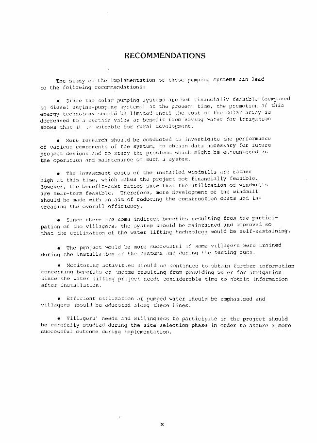
RECOMMENDATIONS
The study on the implementation of these pumping systems can lead
to the following recommendations
Since the solar pumping systems are not financialL feasible (ccepared to diesel engine-pumping sstem) at the presen time the promotion of this
energy technology should he limited until the cost of the solar arzay is
value or benefit from having water for irrigationdecreased to a certain shows that it Ls suitable for rural development
More research shoald be conducted to investigate the performance
of various components of the system to obtain data neces-iry for future
problems which might be eLountered in
project designs and to study the
the operation and maintenance of such a system
Lathera The investment costs of the installed windmills are
this time which makes the project not financially feasiblehigh at
However the benefit-cost ratios show that the utilization of windmills
are near-ter feasible Therefore more development of tne windmill
aim of reducing the construction costs and inshy
creasing the overall efficiency should be made with an
Since there are some indirect benefits resulting from the particishy
pation of the villagers the system should be maintained and improved so
lifting technology would be self-sustaining
that the utilization of the water
o The project would be more successful if some viliagers were trained
the testing runsduring the install3 ion sf the systems and curing
Monitoring activities sAould se continued to obtain further information
concerning bemefits on income resulting from providing water for irrigation
since the water lifting project needs considerable time to obtain information
after installation
Efficient utilization of pumped water should be emphasized and
villagers should be educated along these lines
Villagers needs and willingness to participate in the project should
be carefully studied during the site selection phase in order to assure a more
successful outcome during implementation
x
LIST OF TABLES
Table Title Page
11 Yield and Production of Major Crops (1980) 6
12 Total Agricultural Area VS Irrigated Area 7
21 Average Wind Power Potential 16
22 Windmills Used for Water Pumping in Thailand 17
23 Area and Productiity of Forests in Thailand 18
24 Yield of Selected Fast Growirl Trees 19
25 Research and Development Activities in Thailand 20
26 Number of Biogas Digesters in Thailand 24
27 Diogas Consumption for Typical Equipment 25
31 Technical Data of Thai USAWindmill 39
32 Volatile Solid Loading Rates Used in Various Biogas Plants 47
33 The Operating Detention Time and Dilution Ratio 48
34 Methane Gas Consumption for Various Gas Facilities 49
35 Weight of Excreta Produced per Day by Different
Animals 50
41 Main Occupation of Household Heads 58
42 Subsidiary Occupation of Household Heads 59
43 Land Use and Land Holdings 60
44 Agricultural Production and Incomes in Ban Sukorn Village 61
45 Agricultural Input for Various Types of Crops Grown in Ban Sukorn Village 62
46 Annual Incomes from other Occupations 63
47 Household Expenditures 64
48 Main Occupation of Household Heads 67
49 Subsidiary Occupation of Household Heads 67
xi
LIST OF TABLES (continued)
Table Title Page
410 Land Use and Land Holdings in Ban Tha Yiam Village 68
411 Agricultural Input (Baht per Rai) 69
412 Agrioultiral Input (Baht per Household per Annum) 69
413 Agricultural Production and Annual Income 70
414 Annual Net Income from Agriculture 70
415 Annual Incomes from Other Occupations 71
416 Household Expenditures 71
417 Rice Production and Annual Income 75
418 Rubber Production and Annual Income 76
419 Agricultural Gross Income 77
420 Agricultural Net Income 77
421 Non-agricultural Net Income 77
422 Total Net Income 78
423 Agricultural Input 78
424 Non-agricultural Expense 79
425 Total Household Expenditures 79
426 Test Data of Multi-Blade Windmill 99
427 Test Results and Foreczast for Multi-Blade Windmill 100
428 Test Data of VITA Windioill (Type V-20 B) 107
429 Test Results and Forecast for VITA Windmill 108
51 Cost of Solar Water Pumping System at Ban Sukorn 121
52 Innual Equivalent Cost of the Solar Pumping System at Ban Sukorn 122
53 Cost of Equivalent Diesel Pump 123
54 Annual Equivalent Cost of the Equivalent Diesel Pump 123
55 Cost of Solar Water Pumping System at Ban Tha Yiam 124
56 Annual Equivalent Cost of the Solar Pumping System at Ban Tha Yiam 125
57 Cost of Equivalent Diesel Pump126
xii
LIST OF TABLES (Continued)
Table Title Page
58 Annual Equivalent Cost of the Equivalent Diesel Pump 127
59 Annual Equivalent cost of the Installed Windmills 128
510 Annual Equivalent Cost of the Diesel Pump Equivalent to the Installed Multi-Blade Windmill 129
511 Annual Equivalent Cost of the Diesel Pump Equivalent
to the Installed VITA Windmill 130
xiii
LIST OF FIGURES
Figure Title Page
31 Block Diagram of Gasifier Pumping System 41
41 Typical Curve of Solar Flux Against Time ac Ban Tha Yiam 92
42 Pumping Flow Rate VS rime at Ban Tha Yiam 93
43 Cumulative Energy on Solar Array at Ban Tha Yiam 94
44 Cumulative Pump Discharge at Ban Tha Yiam 95
45 Overall Performance Efficiency VS Solar Flux 96
46 Relationship Between Pump Discharge and Wind Speed
(Multi-Blade) 01
47 Relationship Between Windmill Speed and Wind Speed (Multi-Blade) 102
48 Relationship Between Monthly Pump Discharge and Mean Wind Speed (Multi-Blade) 103
49 Relationship Between Overall Efficiency and Wind Speed (Multi-Blade) 104
410 Relationship Between Volumetric Efficiency and Wind Speed (Multi-Blade) 105
411 Relationship Between Pump Discharge and Wind Speed
(VITA) 109 412 Relrtionship Between Windmill Speed and Wind Speed
110(VITA)
413 Relationship Between Monthly Pump Discharge and Meai Wind Speed (VITA) 111
414 Relationship Between Overall Efficiency and Wind Speed
112(VITA)
415 Volumetric Efficiency of PVC-Ladder Pump 113
xv
LIST OF PHOTOGRAPHS
Photo Title Page
41 The Pradok Reservoir Ban Sukorn 81
42 Villagers Participation 81
43 Land Preparatien at Ban Sukorn 82
44 Concrete Base ConstructioD at Ban Sukorn 82
45 Solar Panel Installation at Ban Sukorn 83
46 The 4300 Wp Solar Cell Pumping System at Ban Sukorn 83
47 Ban Tha Yiam Sa)on Nakhon Province 84
48 Solar Pump at Bar Tha Ylam 85
49 Main Storage Tank at Ban Tha Yiam 85
410 Water Utilization at Ban Tha Yiam 86
411 Bamboo Blade VITA Windmill at Ban Samoh 87
412 Large Multi-Blade Windmill at Ban Samoh 88
413 Small Multi-Blade Windmill at Ban Samoh 89
414 Villagers participation at Ban Samoh 90
xvii
TERMS AND ABBREVIATIONS
AC =
amp =
BC =
BOD =
Btu =
bhp =
C=
COD =
CN =
cm =
DC =
ft =
g =
HP =
hr =
in =
J =
kg =
km =
kW
kWh =
lb =
it =
M=
MSL =
MW =
M6 =
m =
mm =
min =
mW =
alternating current
ampere
benefit-cost ratio
biochemical oxygen demand
British thermal unit
brake horsepower
degree Celsius
chemical oxygen demand
carbon-nitrogen ratio
centimeter
direct current
foot
gravitational acceleration
horsepower
hour
inch
joule
kilogram
kilometer
kilowatt
kilowatt-hour
pound
liter
million Baht
mean sea level
megawatt
Mathayom 6
meter
millimeter
minute
milliwatt
xix
NEA =
O amp M =
P6 =
ppm =
rpm =
s =
UNDP =
V =
VS =
W =
Wp =
wt -
National Energy Administraticn
operation and maintenance
Prathom 6
part per million
revolution per minute
second
United Nations Development Programme
vClt
volatile solid
watt
peak watt
weight
xx
CHAPTER 1
INTRODUCTION
INTRODUCTION
This report summarizes the results of the installation operationand maintenance studies of water pumping systems This project was impleshymented with financial support from the United States Agency for Intershynational Development (USAID) and with technical assistance from the Nationshynal Energy Administration (NEA) Four types of water pumping systemswere considered at the beginning stage of the project These were thesolar water pumping system wind turbine water pumping system gasifierwater pumping system and biogas water pumping system Two solar water pumps and three wind turbine water pumps were installed and operated
A OVERVIEW OF THE COUNTRY
In this section a general description of the geographic and climaticconditions energy and agricultural situation of Thailand is providedto show the background of the country and the need to search for renewable energy sources rather than relying on the fuel oil which must be imported
Geographic and Climatic Condition of Thailand
The Kingdom of Thailand is located in the Indochina penninsulawithin the Southeast Asian continent Her boundary borders Burma andLaos to the north Laos and Kampuchea to the east Burma to the westand Malaysia to the south The specific location is given as betweenlatitudes 50 37 and 20 27 north and between longitudes 970 22 and 1051 37 east
Lying between 6 and 20 degrees north latitude with a rainy seasonfrom mid-May to early November Thailands climate is warm and moist Four torrential rivers the Ping Wang Yom and Nan that rise in thehigh mountains of the north descend through the North and Central secshytions of Thailand flow through the loam-filled delta and empty intothe Gulf of Thailand ThiE low flat area is known as the Central PlainsSoon after entering the plain the four rivers join to form the principalriver of the country the Chao Phraya River This flows for 77 km in a single course and then braids into several channels across the floodplain These reunite after being joined by lesser tributaries andflow into the gulf in two main channels the Chao Phraya and the Thachin River
3
The southwest and northeast monsoons exert a dominant influence on the climate of Thailand The southwest monsoon flowing from the Indian Ocean brings the warm and moist air mass to the country and norshymally extends from about mid-May to October During this period local atmospheric disturbances are common and quite frequent They are geneshyrated in the form of atmospheric low pressure cells of rather short durashytion They are also the chief contributors of rainfall over the country and the basin as well As the season progresses cyclonic storms usually originate in the west Pacific Ocean and the China Sea These storms occasionally approach the basin from the east but before reaching the basin they cross the mountains of Laos and Kampuchea where a lot of their energy is dissipated
With the retreat of the southwest monsoon the rain decreases rapidshyly and the northeast monsoon flowing from the cold and dry Asian mainland starts the winter from November to February There is very little or no rain during this period During the months of March to mid-May the weather is hot and dry it is gradually warmer from the start and April appears to be the hottest month of the year However at the end of this period there will be occasional light rain known as the pre-monsoon rain
According to the above climatic conditions the climate of the basin can be separated into two seasons wet and dry seasons by the characshyteristic of rainfall distribution The wet season is generally defined from May to October and the dry season is from November to April
Thailands Energy and Agricultural Situations
Thailands economics are primarily based on agriculture Rice is vhe main crop Fuels other than wood are mostly imported In this section the energy and agricultural situations of Thailand are briefly described
Thailand-energ situation
Energy is recognized as one of the most essential elements in the development of a country Thailand has undergone several national economic and development plans since 1961 These development activities have resulted in a rapid increase in energy demand by approximately 8 fold during the past 20 years from 2231 million liters of crude oil equivalent in 1962 to 17489 million liters in 1981 Similarly the energy consumption per capita increased approximately 5 fold from 760 liters of crude oil equivalent in 1962 to 3666 liters in 1981
4
Statistics show that Thailand depends heavily on imported crude oil and petroleum products from approximately 50 of the total energy consumption in 1962 to 80 in 1981 An insufficient supply of indigeneous energy has had shy z rious effect cn the national economy The energy import bill in the year 1982 accounted for 587992 M$ or approximately 38 of the total import bill
As a result of the world-wide energy crisis during 1973 the governshyment put great emphasis on tho development of indigeneous energy resources and energy conservation scrategies This policy is well recognized in the Fifth National Social and Economic Development Plan The target can be summarized as follows
0 The energy consumption growth rate has been set at not more than 48 percent per annum
0 The petroleum import is fixed at 3 peicent or less
0 The share of petroleum in the total energy consumption is to be reduced to 46 percent by the end of this plan (1986)
The development of natural gas in the Gulf of Thailand is to be accelerated in order to yield 525 million cuft per day by 1986 A gas separation plant of 350 million cuft capacity is Plso to be comshypleted by that year
The hydroelectric power capacity shall be doubled by 1986 from 1269 MW in 1980 to 2013 MW in 1986
Electricity generation from indigeneous lignite shall be inshycreased from 210 MW in 1980 to 885 MW in 1986
0 Ninety-two percent of the rural villages in Thailand shall be electrified by the end of the plan from 18511 villages in 1980 to 50034 villages in 1986
Petroleum reserve and refinery capacity shall be increased from 36 to 60 days and from 176000 barrels per day to 280000 barrels per day respectively
0 Other new and renewable energy resources such as ethanol fast growing trees mini-hydro biogas agricultural wastes wind solar etc shall be developed and utilized at the annual equivalent of 220shy290 million liters of crude oil by 1986
AgricuZtu2raZ situation
Thailand is an agricultural country Agricultural products have been major exports from Thailand for several decades Rice is the majorproduction item followed by rubber maize and cassava Table 11 shows the yield and production of major crops in Thailand in 1980
5
TABLE 11 YIELD AND PRODUCTION OF MAJOR CROPS (1980)
Crops
Paddy (rice)
Sugar Cane
Cassava
Maize
Coconut
Kenaf
Rubber
Mung beans
Ground nuts
Sorghum
Soy beans
Cotton
Castor beans
Tobaccc
Sesame
Need for Irrigation
Area Planted
(i0 Rai )
47400
738
1194
4250
1856
2356
7775
1300
644
219
300
581
231
138
163
Yield
(kgrai)
2829
69179
25792
4000
3885
1582
363
1307
1926
3200
1600
757
1286
1170
Production
(106 Tons)
1341
5102
3079
1700
721
373
281
170
124
07
048
044
037
020
019
Agricultural production is considered as a national economic indicashytor of the country However in recent years the agricultural economic growth rate has increased very slowly Agricultural yields have remained relatively constant and in some cases have decreased The growth in agricultural output is only due to an expansion of farm land area
With regard to the national interest the expansion of farm land area will contribute serious future problems to the country ie deshyforestation It is therefore necessary to promote and to convince farmers to use other means to increase agricultural yield such as irrigation fertilization mechanization proper uses of pesticides etc
6
Lack of irrigation is generally recognized as an important obstashycle for improving agricultural yields Irrigation can be Achieved by many different approaches eg large reservoir and irrigation canal systems large electrical pumping stations small pumping system etc
Large srale irrigation project implementatinns are currently unoershyway by the Royal Irrigation Department and electricial pumping stations have been promoted successfully by the National Energy Administration Groundwater is one important water source for domestic consumption and irrigation use in many regions However it is suitable for small scale irrigation only and commonly a diesel pump is used in such development
Data on the total farm land area and the area served by existing irrigation projects are shown in Table 12 It was found that the area under irrigation is small compared to the overall agricultural area
TABLE 12 TOTAL AGRICULTURAL AREA VS IRRIGATED AREA
Region Agricvltural Area(106rai) Irrigated Area
rice other total x 106 rai Percent fiela crops
Northeast 292 195 487 16 329
Central 137 185 322 119 3696
North 125 171 296 18 608
South 36 87 123 07 569
Total 590 638 1228 160 1303
Paddy rice plantations are mostly rain-fed The average rainfall is 1500 mm and is sufficient for production of the first rice crop
For the second crop agricultural activities are practiced only in irrigated areas approximately 16 million rai as compared with 123 million rai of total cultivated area
Most of the irrigated areas are in the Central region In the Northshyeast where the total cultivated area is the largest the irrigated area is only 16 million rai
B OBJECTIVES OF THE STUDY
The objectives of this study are as follows
1 To introduce water pumping technologies for field application in rural areas These include solar water pumping wind turbine water pumping gasifier water pumping and biogas water pumping
2 To monitor and test those systems to obtain the results necesshysary for techno-economical evaluation
C SIGNIFICANCE OF THE STUDY
The idea of using renewable energy for pumping water in Thailand has recently stimulated many technologists and developmeitt planners However little information is available for development planners to make any decisions concerning the feasibility of a renewable technology Therefore this project was formulated in order to get first hand reliashyble necessary data and experience for the management of a renewable energy water lifting project Impacts of the study can be classified as follows
Short Term Impacts
The short term impacts of the study include
- Research amp development activities will be formulated to solve hidden problems faced during project implementation
- A large implementation project will be formulated for those watershylifting technologies which are feasible
- Incentive measure for subsidizing those technologies which are near-term feasible will be investigated
- Guidelines for manpower and budget allocations will be outlined for the government institute which will implement the renewable watershypumping project and
- Valuable field results will be available for comparisons with other projects
8
Long Term Impacts
The long term impacts of the study include
- Proven renewable energy water-pumping technology may be recogshynized on the national level as well as the village level
- The Sixth National Economic and Social Development Plan (1987shy1991) may include suitable renewable energy water-lifting technologyactivities in the rural development section andor in the energy development section and
- Guidelines will be available for government decisions relatingto the formation of a renewable energy equipment manufacturing factoryin the country as well as fo research institutions involved in research amp development efforts which are geared towards obtaining necessary inshycountry technology
D SCOPE OF WORK
Energy sources for supplying water for irrigation are varied Howeverin the context of this study we will focus on small scale irrigationat a place where water is available to individual farmers or to a small community where the land area is not greater than 200 rai Based onthese criteria solar energy technology wind energy technology gasifishycation technology and biogas technology have been selected
9
CHAPTER 2
REVIEW OF LITERATURE
7p1
REVIEW OF LITERATURE
In this chapter available reports and documents concerning the deshyvelopment of various renewable energy technologies are reviewed and sumshymarized These include solar energy technology wind eneplusmnLy technology gasification energy technology and biogas energy technology
A SOLAR ENERGY TECHNOLOGY
At present utilization of solar energy can be classified into 2 main categories ie the solar thermal system and the solar electrical system
Solar Thermal System
Technologies utilizing the solar thermal process were developed in the 1870s A solar steam engine of several horsepower was developed byMouchot and Pifre in France in 1870 A 50-HP solar irrigation pumping engine was fabricated and tested by Shuman and Bous in Egypt in 1913 Later internal combustion engines were developed These engines became available at cheaper prices and were very efficient Therefore the deshyveloped solar pumping system was replaced by these engines
After the world oil energy crisis interest once again was paid to the development of the solar pumping system The most recent developmentsin the solar thermal pumping system involve the use of organic solutions as a working fluid in contrast to the pioneer work that used steam as a working fluid
Recently the Sofretes Company placed approximately 50 solar thermal pumps on the market However field results show that this was not a goodtime for marketing these items Nevertheless several organizations are still putting efforts into developing new variations of the solar- thermal pumping system eg Ormat (Israel) Dornier (West Germany) Solar PumpCoorporation (USA) Hindustan Brown Boveri (India) Sun Power Systems(USA) Grinakers (Pty) Ltd (Johannesburg) etc
At this point it can be concluded that at the time of project plannshying there was no potentially viable solar thermal pumping system availashyble on a commercial basis in the world market Howeve promising developshyments are slated to come out in the near future
Solar Electrical System
The conversion of solar energy into electricity can be achieved by a photovoltaic process therefore this system is sometimes referred to
g13
as a photovoltaic system This technology was developed in early 1839
However utilization as an energy source was very slow due to its very
high investment cost Even so this technology has been used for powershy
ing satellites
In recent year advancements in electronic development have resulted
in the production of solar cells which are more efficient with less cost
In contrast the prices of conventional fuels hav3 been sharply increasshy
ing Thus the use of solar cells for electricity generation has received
more attention
The only type of photovoltaic cell commercially availabie today is
the silicon cell in the mono-crystalline and polycrysualline form Cell
efficiency is within the 10-14 range for monocrystalline cells and 9-10
for polycrystalline cells
Tremendous efforts by researchers and scientists in various regions
of the world have provided relevant information indicating the production
of new photovoltaic cells in the near future These new solar cells
will be either higher in performance or lower in cost and may be made
from other materials eg gallium-arsenide cells cuprous sulfide cells
or cadmium sulfide cells etc
The cost of silicon solar cells has dropped substantially from
US $ 2000Wp in 1958 to US $ 30Wp in 1976 and tc US $ 8Wp in 1983
With improvements in the manufacturing processes and techniques the cost
of solar cells is expected to be reduced to approximately US $ 050Wp
by 1990 (1980 price)
Photovoltaic Pumping System
A photovoltaic pumping system usually consists of a photovoltaic
(solar cell) array a battery a motor and pump set and a controller
A recent investigation of solar water pumping technology (UNDP
Project GLO78004 executed by the World Bank) revealed that there were
numerous relatively minor problems being experienced during the project
field testing of 12 solar pump systems in Mali the Philippines and the
Sudan These problems were due to incorrect wiring poor electrical tershy
minal amp connection electronic failure broken module cover glasses air
locks in the suction pipe footvalves jamming or leaking etc It is
anticipated that these problems can be solved as more experience is obshy
tained during the course of solar pump development
13 WIND ENERGY TECHNOLOGY
One traditional form of energy used for several centuries is wind
energy Several types of windmills are commonly seen being used for
brine pumping along the Gulf of Thailand and for rice irrigation in the
Chao Phraya delta In this section information concerning wind energy
use in Thailand is reviewedtechnology and its potential
14
Wind Energy Potential in Thailand
The output of a windmill depends on the wind speed available at the site Wind velocity continually varies in both magnitude and direction However it is broadly predictable over a significant time period Stashytistics show that there is approximately a 7-14 kmhour average wind speed available in Thailand A recent study predicted that the highest mean wind speed occurs along the coastline and in the2 southern part of Thailand 5he wind power density ranges from 76 Wm at Mae Hong Son to 718 Wm at Songkhla Table 21 summarizes the average wind power poshytential in various parts of Thailand
Wind Energy Development Technology
At present there are three basic types of windmills the slow-speed sail rotor type the high-speed wooden rotor type and the multi-blade steel rotor type
Windmills of multi-blade type are now used for pumping water for consumption and household needs For irrigation needs improved windmills of a sail rotor type are being promoted However the high speed wooden blade type is rarely seen since it requires a higher starting wind speed Table 22 shows an estimate of windmills Presently in use
C GASIFICATION ENERGY TECHNOLOGY
Gasification Technology was utilized in Thailand during the late World War II period when fossil fuels were scarce However thi3 techshynology was abandoned in the post war years when low petroleum -iices reappeared
Interest in utilizing this technology again become high after the world energy crisis of the 1970s The technology attracted researchers and government planners around the world as it appeared to be suitable for use in rural areas to run engines for shaft power or for producing elcctricity
Run on atlocally available wood or charcoal a gasifier converts biomass fuels into a combustible gas mainly carbon monoxide (CO) which can be used to substitute up to 80 of the diesel fuel needed for diesel engines or entirely substitute the gasoline fuel used in gasoline engines
Availability of Biomass Material
Wood and charcoal are ma3or fuel sources for rural people They are available locally and inexpensively compared to other conventional
15
Place
Bangkok
Koh Samui
Khon Kaen
Khlong Yai
Chonburi
Chaiyaphum
Chiang Mai
Don Muang
Tak
Korat
Nakorn Sri Thammarat
Nan
Prachin Buri
Phitsanulok
Phrae
Phuket Airport
Mae Sot
Mae Hong Son
Ranong
Loei
Sakhon Nakhon
Suparn Buri
Surat Thani
Nong Kai
Hua Hin
Uttaradit
TABLE 21
AVERAGE WIND FOWER POTENTIAL
Wind Power Wind Power
Potential Place Potential (kwkm2 ) (kwkm2 )
6184 Kanchanaburi 8509
29592 Koh Sichang 19038
5448 Phumipol Dam 6576
8379 Chantaburi 3977
14216 Chum Phon 24125
9515 Chiang Rai 3800
5507 Sap Muang 6561
40970 Trang 20728
10577 Nakhon Phanom 5324
4391 Prachuap Khri Khan 17996
8722 Narathiwat 11943
2122 Pattani 12021
5411 Phetchabun 6184
2010 Phuket 6121
5349 Mukdahan 11020
28968 Mae Sariang 2440
11227 Roi-et 6775
1525 Lop Buri 7537
8163 Lam Pang 3081
5239 Songkhla 32799
9885 Surin 4279
9091 Sattahip 36292
4732 Hat Yai 16972
4099 Aranyaprathet 4360
13120 Udon Thani 2483
1364 Ubon Ratchathani 17372
Source Panich Banterng Boonchai and Kwan (1981)
16
TABLE 22 WINDMILLS USED FOR WATEP PUMPING IN THAILAND
SPrice Nomenclature No in Use Maniacturer P Technical Data(Bht
A Pooular windmilZs3 Isc Bamboo Mat Sail Type 3000 Villager 9500 Blade Diameter 6-8 m
3Local factory Pumping Capacity 46 m hr Total Lift Head 06 m Wind Velocity [3 kmhr
2-4 Wooden Blades Type 3000 Villager 1200 Blade Diameter 6-8 m (Cha Chueng Sao) Local factory Pumping Capacity 90 m3hr
Total Lift Head 09 m Wind Velocity 21 kmhr
Multi-Blade Type (USA) 1500 Thai USA See See Table 31
Table 31
Multi-Blade Type 300 Chonburi Unknown Unknown
B Yew dvetoDed winzamills
Sail Wing Type (NEA) 20 National Energy 12000
Administration Sail Wing Type (KU) 3 Kasetsart 12000 Blade Diameter 4 m
University Pumping Capacity 17 m3hr
Total Lift Head 45 m Wind Velocity i0-12 kmhr
Cycle Wheel Type 2 Songkhla 12000 Blade Diameter 32 m
University Shaft Power 125 w Wind Velocity 3 ms
Multi-Blade Type 8 King Mongkuts 33000 Blade Diameter 3-4 a institute of Piston Diameter 4 m Technology No data test
Sail Wing Type 20 American Volunteer Unknown Designed by Sahores
Savorous Type 10 Several Organiza- Unknown Low efficiency
tions
Augmented Turbine 2 Kamthorn Unknown Sail Wing Data 38 m
Plysummit Turbine Diameter I2 m Height of Turbine 12 m
Pumiing Capacity 04b mmin Total Lift lead 05 m Wind Velocity 10 kmhr
SourceNational Research Council Bangkok(1981)
17
fuels Charcoal is the best fuel source to feed a gasifier However considering the fact that there is a loss in energy of approximately 70 percent in converting wood to charcoal it appears that wood would be the better choice Unfortunately there are few acceptable small wood
gasifiers on the world market today that are able to produce tar free gases suitable for use in an internal combustion engine
Another unfortunate fact is that even though wood fuels seem to be substantial available locally (as3 shown in Table 23) energywise the
quantity of wood (1289 million m ) is roughly comparable to only 1000 million barrels of crude oil or approximately 6 of the total national energy consumption in 1982 Nevertheless wood fuels are presently an
important resourcefirst as a source of cooking fuel for rural people secondly as a resource in the wood industry and third for use by
the country as a natural forest
Therefore if the wood or charcoal gasifier is to be promoted on a
national scale it is essential that the woodlot plantation be implemented where the gasifier is used
Fast growing tree species suitable for Thailands soil and climatic
condition are the Eucalyptus Camaldulesis and the Casuarina Junghuniona Table 24 shows the estimated yield of these tree species
TABLE 23 AREA AND PRODUCTIVITY OF FORESTS IN THAILAND
Prcductivity Growing stock3 Region Area (million ha) (m3ha) Volume (1036 m
North 113 33 599
223Northeast 78 29
Central 47 46 220
77 247South 32
Total 270 48 1289
18
TABLE 24 YIELD OF SELECTED FAST GROWING TREES
Yield Species
(m3hayear)
EucaZyptus camaldulesis (moderate management 5 years old) 18-75
Casuarinajunghuniana (intensive management 5 years rotation) 13-44
Other (poor management 10 years old) 10-15
Present Status of the Technology
Combustible gases from biomass can be produced from a device called a gasifier This device may be classified into three basic types Upshydraft gasifier downdraft gasifier and crossdraft gasifier
In the updraft gasifier the air is taken in through a grate at the bottom of the gasifier and the biomass fuel is fed from the top The direction of air flow is reversed in the case of a downdraft gasifier In the crossdraft gasifier air is introduced through a horizontal nozzle in the wall of the gasifier and the gas is taken out the opposite side The main difference between the updraft and downdraft gasifiers is that more combustible gases are generated in the updraft gasifier and more clean gases are produced in the downdraft gasifier when generating comshybustible gases for an internal combustion engine As stated earlier gasification technology was once abandoned because it was not economical compared with the cheaper fossil fuels during and after the post-war period Also there are many minor problems associated with the use of gasifier engines they require intensive maintenance they are difficult to start they require a skilled operator there is a health hazard if not used properly and no design currently exists for a gasifier that is able to use all types of iomass and charcoal
It is therefore not surprising that many research and development activities in Thailand (as shown in Table 25) are attempting to improve the weakness associated with a gasifier and to demonstrate that it is an economical energy choice
19
TABLE 25 RESEARCH AND DEVELOPMENT ACTIVITIES TN THAILAND
Institute asiferEnd use Status and engine
] Department of Agri- Updraft 5 HlP Charcoal Water pumping Under improvement cultural Technology Gasoline engine since 1980
2 Prince of Songkhla University
Downdraft 5 HP Commercial charcoal Electricity Experimenal plant gasoline engine Rubber tree charcoal operated more than coupled to 2 kWe 500 hr since 1980 generator
Downdraft 35 11P Commercial charcoal Electricity In operation for gasoline engine Rubber tree charcoal aoproximately driving 110 kWe Rubber tree wood 1000 hr generator Coconut shell
Downdraft 24 HP Commercial charcoal Electricity Under performance diesel eneine Rubber tree charcoal driving al0 kWe Rubber tree wood generator
huialongkorn niverityDowndraft 500 We Charcoal Electricity Under construction
Downdraft HP cubed rice straw Water pumping Under construction
Downdraft 14 HP Wood Water pumping Under construction
Fluidized bed Rice Husk deing planned
Downdraft 25 kWe Corn cobswood chips Electricity Under construction
Downdraft -O kWe Rice Husks Electricity Being planned
King ongkuts Updraft Charcoal Water pumping Under improvement Institute of since 1981 Technology (North Bangkok Campus)
5 Departmnr of Downdraft 25 HP Charcoal woud in operation since1ElectricityPublic Works gasoline engine 1982
coupled to [5 kWe generator
6 National Security Downdraft 12 kWe ICharcoal Electricity In operation at Command leadguarera I Kumdogmai villageCin
Udorn rhani province since 198
20
TABLE 25 (CONT)
Institute Gasifier typeand engine
Fuel End use Status
7 Kinistry of Industry Downdraft 12 kWe Charcoal wood Electricity Field test to start
in 1983
8 Kampangphet Provin- Downdraft 3 kWe Charcoal Electricity In operation cial Public Works office
9 Patumwan Technical Institute
Downdraft 16 HP engine coupled to
Charcoal Electricity Under improvement since 1982
generator
Downdraft 12 kWe Charcoal Electricity
10 The Royal Forest Department (RFD)
Downdraft 10 kWe Wood Electricity Under improvement since 1982
11 National Energy Administration (NEA)
Downdraft 5 HP Charcoal wood Water pumping Under performance gasoline engine testing
Downdraft 30 HFP Charcoal wood Electricity Test scheme to gasoline engine start July 1983 coupled to LO kWe generator
21
TABLE 25 (CONT)
Institute Gasoline type Fuel End use Status and engine
12 Private sector Kanjanaburi
Updraft 120 HP Charcoal Passenger boat In operation on the diesel engine River Qai in
Kanjanaburi Province since 1981
Updraft 260 IP Charcoal Rice mill In operation at
diesel engine Amnuaypol mill in Supanburi province since 1981
Updraft Charcoal Electricity In operation
13 Prasathong cinema Updraft Charcoal Electricity In operation since Supanburi 1981
14 Private sector Updraft 260 HP Charcoal ligrite Ice-making In operation since Petchabul diesel engine 1981
driving a compresshysor 150 HP
15 Private sector Updraft 160 HP Rice husk Electricity In operation since Chacherngsao diesel engine 1982
116Srimaharacha Co Downdraft 12 kWe Charcoal wood Electricity Under improvement since 1980
17 VS Factory Downdraft Wood anthracite j Burner Under improvement for commercialization since 1983
Source National Energy Administratlon
22
D BIOGAS ENERGY TECHNOLOGY
Overview
Biogas has been known for decades Sanitary engineers are familiar with the treatment of domestic sewage sludge and organic wastes by methane digestion A methane is a container which keeps organic wastes in such a manner that natural bacterial degradation of the organic matter occurs in the absence of oxygen In other words methane digestion is an anaeroshybic process in which organic wastes are converted to methane gas and carshybon dioxide For animal manures the anaerobic process yields approximateshyly 55-65 percent methane 35-45 percent carbon dioxide and very small amounts of nitrogen hydrogen oxygen and hydrogen sulfide
In anaerobic digestion organic matters are mixed with large populashytions of micro-organisms under the absence of oxygen Initially there is no methane formation Complex organic materials such as fats proteinsand carbohydrates are biologically converted to organic fatty acids byacid-forming bacteria Later on the organic acids are converted to meshythane and carbon dioxide by methane forming bacteria
The gases yielded from the process are commonly known as biogas It is combustible and can be used as a substitute for fossil fuel for lighting cooking gas engines gas refrigerators etc
Availability of Biomass Material for Biogas Generation
Various biomass materials and organic wastes can be used as a raw material for a methane digester At present animal manures are the most popular choice for rural people Other materials can be used but they need to satisfy certain conditions if high energy gas is required For an agricultural country like Thailand these biomass materials are availshyable in excess provided a proper collection is instituted
Status of Technology
Biogas digesters have been utilized by the Sanitation Division of the Health Department in rural areas since 1970 These were primarilyintroduced for public health and welfare reasons as the biogas digester gets rid of undesirable wastes that can cause serious diseases among rural people
Later on the National Energy Administration began an extensive program for the demonstration and promotion of biogas digesters in order to produce combustible gas fertilizer in addition to the environmental and health protection aspect
Several biogas digester designs exist in Thailand at present The Chinese and Indian designs have been modified and adapted to suit Thailands
23
local conditions Several other types of biogas digesters also exist eg the Thai water jar type and the Taiwan rubber bag type
The promotion of biogas utilization as an energy substitute has beshygun recently The campaign is considered to be a joint venture by the National Energy Administration (NEA) and wiveral public and private orshyganizations eg the H-alth Department the Public Welfare Department the Agricultural Extension Department the Co-operative Promotion Departshyment the Community Development Department the Office of Adcelerated Rural Developmentetc
Table 26 shows the number of biogas digesters available in Thailand as compnild bv the NEA in 1984 During 1970-1983 there were more than 4953 niogas digesters in the country Two were community biogas plants for electricity production for a typical sized village in the Northeastern region
TABLE 26 NUMBER OF BIOGAS DIGESTERS IN THAILAND
Year Noof Digesters
1970-1976 207
1977 41
1978 23
1979 151
1980 370
1981 643
1982 1668
1983 1790
Remark incomplete information
24
Biogas utilization can be applied to cooking lighting heating electrical power or mechanical power Some adjustment or adaptation of the energy equipment is needed in order to operate them with a biogas Table 27 indicates the typical rate of biogas consumption for various equipments under normal operating conditions
TABLE 27 BIOGAS CONSUMPTION FOR TYPICAL EQUIPMENT
Item Consumption
3Lighting 25-3 ft per mantle per hour
Cooking 11-16 ft3 per hour per 2-4 in burner 12-15 ft 3 per person per day
Gas Refrigerator 11 ft3 per hour per cubic foot
Gasoline Engine 17 ft3 per bhp per hour
25
CHAPTER 3
BASIC DESIGN OF THE STUDY
BASIC DESIGN OF THE STUDY
In this chapter the system performance the basic design considerashytions plus the operation and maintenance of four types of water pumpingsystems are described These include the solar water pumping system thewind turbine water pumping system the gasifier water pumping system and the bioqas water pumping system
A SOLAR PUMPING SYSTEM
System Performance
The solar water pumping system consists of a number of solar cellsa direct current (DC) motor and a water pump The solar cells convertthe solar energy into an electrical energy this is known as a photovolshytaic system The electricity produced is then used to drive the DC motorand the water pump This water pumping system holds great promise forsmall-scale irrigation and for supplying a community domestic water supply
The key element of the solar module is the silicon solar cell Eachsolar cell has an electrical potential of about one-half volt when exposedto bright sunlight Peak power will be produced at 045 to 048 volts percell The amperage of a cell is dependent on the cells area An assemshybly of these solar cells wired in series makes up a solar module Toproduce the required ampere-hoursday for a water pumping system a numberof modules are assembled on a support structure making array thean with required output
A photovoltaic array consists of several photovoltaic (solar cell)panels which ore arranged in series and parallel according to specificpurposes Each panel converts sunlight to electricity through siliconcells which are approximately 100 mm in diameter and either square ortriangular in shape Each cell produces 25 milliamperes of d rect curshyrent per square centimeter under solara irradiance of I kWm at 25 Celshycius and approximately 05 volts under nominal operating conditions These cells are usually connected in a series or string to build a volshytage up to a required level The cells are sandwiched to form a rectangushylar panel and covered with either glass or clear plastic
An important feature of a solar panel (module) is that it should berugged and capable of resisting ultra-violet radiation thermal cyclingshock moisture penetration etc in order to sustain its performance even under severe operating conditions
29
A solar module is usually rated in terms of Peak Watt i2 e the
power a module can produce at an irradiance of 100 Watts per cm at 25
Celcius
The battery stores the electrical energy which is prcduced through
an electrochemical process In the photovoltaic system a battery can
store excess energy and deliver electricity to load when there is no soshy
lar radiation Therefore the addition of a battery in a system will
facilitate operation guarantee that a system will provide power at any
time and act as a power buffer between an array output and load Howshy
ever several disadvantages are also built-in when using a battery for
example high capital investment and extra control equipment is needed
to regulate the charging operations
Batteries are usually rated in terms of their ampere-hour capacity
Other important specifications include rated voltage operating temperashy
ture self-discharge rate rated current life-cycle size weight and
cost
A motor amp pump set in solar pumping applications has a variety of
combinations For a motor there are choices between a brush or brushshy
less direct current (DC) motor an alternating current (AC) motor with DC
to AC inverter or a motor with a maximum power point tracker For the
pump there is a choice of a centrifugal pump a rotary pump a piston
pump or a submersible pump etc
Today there is no designated motor and pump combination which
would generally be accepted as the best In the selection of a motor and
pump set the following should be considered the water requirement and
head conditions the meshing between the motor and pump set with the solar
cell array the water needs and its duration environmental and operating
conditions etc
Nevertheless experiences to date have lead to the following conclushy
sions
0 For systems up 1 HP a DC motor with a permanent magnet is
generally used
or an
AC motor are most commonly accepted For systems of 1-3 HP a DC motor of a shunt field type
For systems above 3 HP
A maximun power point tracker is an electronic controller used to
mesh the power from a solar array to the load This device may cause some
breakdown during operation Therefore if the system is well designed
the deployment of the controller in the system is unnecessary
When a dynamic head dominates a centrifugal pump is favored while
in other cases batteries or sophisticated controls should be used to reduce
30
useful energy losses from mismatching and
0 The incroduction of batteries or sophisticated controls are exshypensive and require extra maintenance
The pumpmotor should be securely mounted to a foundation that is leshyvel and free from movement in an area clear of materials that could intershyfere with the operation of the upit It should be located as near the source of water as practical to minimize the vertical lift of water to the pump and so that a short suction pipe with a minimum number of fittshyings can be used to keep the pipe friction loss as low as possible
A strainer should be installed at the inlet end of the suction pipe to prevent solids from clogging the pump The selection of the pipe size is dependent on the flow rate
If possible shelter should be provided for the pump and motor unit to protect them from the weather Adequate space around the pump should be provided for service and ventilation when it is running
A typical system efficiency may be set for each component as follows
array cell 11
connection 95
motor 85
pump 50-55
pipe work 95
battery 80 (if used otherwise 100)
impedance mismatch 70-90 (if using an electronic controller 24gt
other miscellaneous 90
Total for system 21-39
The efficiency f a photovoltaic pumping system varies depending on many factors egthe combination of components the efficiency of composhynents operating conditions etc
Basic Design Considerations
In the design of a solar water pumping system the following items should be considered
General requirements
The system should be designed to survive particular local climatic conditions In areas prone to typhoons or hurricanes it may be necessary to provide for the rapid dismantling and removal to safety of the array
e Pumps and motors should be provided with sunshades whenever possishyble but the unit must remain well ventilated if air-cooled
e Materials exposed to solar radiation (such as plastics) should have proven durability
Modules should be individually packed to avoid damage in transit The safety of the contents should not be dependent on receiving special handling treatment
Detailed instructions should be provided in the local language for the correct assembly of the system Also included should be a comshyponents list maintenance and operating instructions and guidance on how to achieve the best output All documents should be written in simple terms and
The need for routine mainterance lubrication and readjustments should be minimized and avoided if possible
Array and module requirements
The array should be manufactured with a lifetime guarantee of at least 5 years against faulty quality with no more than 10 degradation of performance
Small modules (less than a 20 W nominal rating) are preferred
It should be installed either with a laminated glass or an impershyvious and ultra-violet resistant plastic cover
Optimum module cell efficiency should exceed 11
There should be no air gap between the cell encapsulant and the cover glass
It should be equipped with generously sized (brass) terminals with grip screws or with appropriate plug and socket connectors
Array nominal voltage under peak sunlight conditions should be around 50 V higher voltages will not be safe while lower voltages will mean higher currents and larger resistive losses and
e Quality assurance and testing to a satisfactory standard should be specified by the manufacturer Module or array performance should be specified on the basis of tests to a stated international standard The modulearray area to which array efficiency is referred must oe clearly defined
Motor and purp
A DC permanent magnet motor is preferred unless the alternative is shown to be of comparable efficiency
32
0 Full load motor efficiency should exceed 85
Half-load motor efficiency should exceed 75
e Motor bearings and other -omponents should be sized for a life in excess of 10000 hours
e Submersible units are preferred to eliminate suction problems
If the motor is not submersible couplings between the motor and p imp should permit significant motor and pump angular andor parallel msalignment
9 Motor and pump bearings should-be entirely independent except in the case of integral submersible motor-pump units
0 Thermal cut-out is required on the motor unless the motor can sustain continuous stalled conditions with the maximum array current
6 The pumps optimum efficiency should be in excess of 50
The pump should be capable of self-priming in the event of a leakshying footvalve (where fitted)
Impeller material clearances and passages should be suitable for use with water containing suspended silt andor corrosive salts Open impellers are preferred
e Where necessary a suitable strainer for larger particles should be provided and should be sized so as to have a negligible effect on pershyformance while clear
4 Pump should have bearings Jized for 10000 hours of operation and should be supplied with spare seals plus any other consumables to cover that period of operation ball bearings with greased seals are preferred
Pump characteristics should permit stable operation at sub-optimum speeds
The pump should be capable of running dry without serious damageif not a submersible type alternatively a fail-safe method of protection from runnin3 when dry should be provided (with seals designed to suit) and
Pipework and fittings should be correctly optimized for minimum system cost rather than minimum pipework cost all pipework should be supplied with system to length specified for head and site
Specifications for the Installed Solar Pumping Systems
In purchasing solar pumping units for this project the following specifications were given
33
General requirements
0 The systems shall be provided for DC pumping to be used for irrishygation or water supply Each system shall include
- Photovoltaic modules and array support structure
- Required motor and pump set(s)
- One spare motor and pump set
- All necessary control equipment and wiring
- A voltmeter and an ampere meter to m Lsure voltage and current from the solar cell array
- All fixings and auxiliaries necessary for complete construction
- All special tools needed for assembly and maintenance
- Spare parts recommended for three full years of operation (inshycluding motor brushes if applicable) and
- Any other components necessary or recommended in order to proshyvide reliable safe operation andor optimum efficiency
All components except fuses and lamps shall be guaranteed against defects in design workmanship and material for a period of 1 year
Each system shall be designed to operate under the following enshyvironmental conditions
- Ambient air temperature between 0 C - 45 C
- Relative humidity up to 95 at an ambient temperature of 40 C
- Wind speed up to 100 kilometers per hour
- Water source temperature up to 35 C
- Water source containing particles not exceeding 03 mm and
- Annual average daily insolation is 176 MJm2 per day
Each system slall be able to pump water when solar radiation is more than 400 wattsm
The solar cell unit shall be a single crystalline silicon type and the solar module shall be a complete sealed unit consisting of a number 6f solar cells in series or series-parallel combination Solar arrays are a number of solar modules connected in a series or series-pashyrallel qombination and mounted in an array frame
34
9 The solar cell module shall have a conversion efficiency equal o or greater than 8 when measured under standard conditions of 100 mWcm at 25C cell temperature
Electrical termination shall be either screw-type or cable suishytably sealed at the entry to the solar module All terminals shall be electrically isolated from any metal frame or support
The surface of the module shall be tough transparent plastic or toughened glass capable of withstanding without damage any stresses imposed as a result of temperature cycling wind pressure resulting from wind velocity and other environmental changes
The solar array shall be mounted on a flat surface with the range of angle adjustment (the incline angle) variable from 15 to 35 degrees
The array frame material shall resist corrosion when installed in tropical conditions Stainless steel aluminium and hot dipped galvanized miie steel are considered to be satisfactory array frame materials
e All fasteners and associated components shall be compatible with the array frame and solar modules used to avoid corrosion Modules shall be mounted so that they can be removed from the front by one person and all cables and interconnections shall be arranged for easy replacement
Where a number of solar modules are connected in series-parallel combinations the operation of any onp parallel string of modules shall not affect the operation of any other string in the event of (a) failure of a module(s) in a parallel string andor (b) shading of a module(s) in a parallel string Blocking or isolating diodes shall be connected in series with each parallel series of modules
All cables shall be generous in cross-section to limit resistive losses at full power to no more than 5 blocking diodes to result in no more than 2 loss at full power
In this water pumping project 3 units of solar water pumps were installed These included a 4300-watt unit for irrigation purposes a 700-watt unit for domestic water supply and a 300-watt unit for a microshyirrigation system The designs of these solar pumping units were as follows -
The 4300-watt irrigation system
The system was designed for installation at Sukorn Village Chumshyphuang District Nakhon Ratchasima Province latitude 14 58 N longishytude 102 07E elevation of station 188 meters above MSL average ambient temperature 27 C
The nominal maximum power at the standard condition (100 mWcm
at 25 C) of the solar cell shall be at least 4300 watts to assure with
35
2
adequate safety factor a total water discharge of more than 480 m3day at 5 meters head (static suction lift is 3plusmn1 meters)
0 The maximum number of motor and pump sets employed in the systemshall be 5 units (not including the spare set) All units shall be identical
Permanent magnet DCmotor(s) shall be employed with an efficiencyof more than 75 of their design rating The pump(s) shall be of the self-priming centrifugal type
The solar array frame shall be designed so that it is suitable to install on a concrete slab with the lower edge of the frai 15 meters above the ground
The system shall include an automatic cut-out with automatic reset to protect the system from excessive temperature voltage or current and
The system shall include monitoringcontrol box(es) designed fortropical conditions and high ambient temperatures for the following items
- Maximum power controller or maximum power point tracker if employed
- Automatic cut-out with automatic reset if employed and
- A voltmeter and ampere meter to measure voltage and current from the solar cell array
The 700-watt water supply system
The system is designed for installation at Ban Tha Yiam (Village1) Non Hom Sakon Nakhon Province latitude 17degN longitude 104E average ambient temperature 27C
The well characteristics are as follows
- Draw-down depth 95 m for static water level
- Maximum P-i inissible pumping rate 094 liLerssec
- Chlorine is less than 30 ppm
- Iron is less than 25 ppm
- pH is 78
- Total hardness is 142 ppm as CaCO3
- Total dissolved solid is 248 ppm
- Static water level is 8 m below ground level and
- Depth of casing is 24 meters
36
2 The nominal maximum power at the standard condition (100 mWcm
at 25C) of the solar cells shall be at least 700 watts to assure with a~equate safety factors a total system water discharge of more than 10 m day at 215 meters total dynamic head
A permanent magnet DC motor shall be employed with an efficiency of more than 75 of its design rating The pump shall be a centrifugal pump or a suitable substitute recommended by the contractor If a piston pump is employed a maximum power controller shall be required
The solar array frame shall be designed so that it is suitable for installation on a concrete slab with the lower edge of the frame 15 m above the ground
The system shall include an automatic cut-out with automatic reset to protect the system from excessive temperatures voltage or current
The system shall include monitoring control box(es) designed for tropical conditions and high ambient temperatures for the following items
- Maximum power controller if employed
- Automatic cut-out with automatic reset if employed
- Voltmeter and ampere meter to measure voltage and current from the solar cell array
All necessary piping and connections shall be provided Pipe drop to the well shall be approximately 12 meters
The 300-watt rnicro-irrigation sgstem
e The nominal maximum power at the standard condition (100 mWcm2
at 25C) of the solar cell modules shall be at least 300 watts to3 assure with adequate safety factors a water discharge of more than 50 m day at 3 m head
The system shall not employ a battery
A DC motor shall be employed and be of the permanent magnet typeits efficiency shall be more than 75 at the design condition The pumpshall be a self priming centrifugal pump or a suitable substitute recomshymended by the contractor and
e The system shall include a strainer a flexible pipe or hose of not less than 3 m in length for suction and a flexible pipe or hose of not less than 5 m in length for discharge
37
B WIND TURBINE PUMPING SYSTEM
System Performance
The wind turbine is a device which converts wind energy into mechanical energy This mechanical energy is then used to drive a water pump A positive displacement pump is used in this installation This system was used for farm irrigation several hundred years age
Technical Design
For locally made windmills in Thailand very little information on technical performance is available This is partly due to the fact that there is no acceptable standard testing precedure Some typical windmill performance data are taken from manufacturers information sheets
Thai USA windmills
These are steel multiblade windmills 8-20 ft in diameter The Thai USA windmill has 20-45 blades with a piston pump 25-18 inches in diameter It is claimed that these windmills can lift water at verylow speeds Table 31 shows typical performance data for these windmills manufactured at the Thai USA Industrial Factory Bangkok
Vita windmill
The Vita windmill is designed for irrigation where a large volume of water is needed at low head The rotor of this type of windmill is approximately 6 m in diameter with 8 bamboo or laminated wood blades A modified rotary chain ladder pump with a 4-10 in diameter is used Power extracted from the wind stream is transmitted to a pump by a 4shyinch industrial belt
The VITA windmill was recently developed in Thailand by Volunteers in Technical Assistance Asia field office (VITA Asia field office)At jLiesent they are being manufactured and marketed by the Windmill Pump Co Ltd Thailand The cost of one complete system is 45000shy78000 Baht
The VITA windmill V-8 type has a maximum pumping rate of 4000 liters per minute with a starting wind speed of 3 meters per second and a maximum design wind speed of 140 kilometers per hour The manufacturer claims that the unit has a 15 year working lfe (75000 hours) with a water cost of approximately 002 Baht per m of water pumped when being operated at 33 ms and one meter lift
The NEA 8ail type windmill
The National Energy Administration (NEA) has developed a low cost windmill which is easily fabricated from locally available materials
38
tABLE 31 tECHNICAL DATA OF THAI USA WINDMILL
Blade Dia Height No of Blade Piston Dia Water pumped Wind Velocity Price Note (ft) (in) (in) (Ithr) (kmhr) (Baht)
8 15 20 25 1200 10 28000 1) Price effective
10 15 30 3 2000 10 35000 Sept 27 1982
12 15 30 45 2500 10 51000 2) Excluding
14 15 30 6 6000 10 64000 installation
14 15 30 10 12000 10 71500 3) Installation cos
16 15 45 12 16000 10 93000 charge is3500-4500 Baht
18 15 45 16 20000 10 100000 depending on
20 15 45 18 24000 10 120000 distance
39
The unit is a typical old-fashioned sail type windmill However several improvements have been made The NEA Sail Type windmill (model WE 002) has 8 sail wings attached to 540 m long wooden spars 2Each sail wing is made of a plastic coated fabric within area of 24 m The rotor diashymeter is 6 meters with a steel shaft for mechanical power transmission The piston pump is a single stroke type with a displacement of 125 mm The piston rod is 76 mm in diameter and is made with a thick PVC piston bore and a camel leather piston ring
Specifications of the Installed Windmills
In this study three windmills were installed in Ban Samoh Tambon Ta-tong Amphue Raman Yala Province These included two multiblade windshymills and a VITA type (V-20B) windmill
The multi-biade windmill
Each blade is made of a galvanized steel sheet fixed on the L-shaped steel frame The diameter of the wind blade is 305 m (10 ft) This wind blade is installed on a steel support at an elevation of 12 m above ground level
The water pumping system is a single stoke type with a piston diashymeter of 75 cm (3 inches) The stoke length is 75 cm (3 inches) and
The water well is a dug well with the water table 450 m below ground level
The V-20B type vita windmill
There are 25 blades made of bamboo and fixed to an L-shaped steel frame The center of the blades is approximately 75 m above ground level
Water pumping is accomplished by using a PVC ladder pump with a 6-inch diameter and
This windmill will provide high starting torgue and low speed which is suitable for the ladder pump The blades can start the pump with a wind speed of 4 ms and will continue rotating as long as the wind speed does not drop below 2 ms
C GASIFIER PUMPING SYSTEM
The gasifier pumping system consists of a reactor a feeding bin a gas cleaner and cooler a mixing box an int ial combustion engine and pump set (Figure 31)
40
biomass
colder gas hoth
dirty gas
gReactor c s Cleaner bo mn xi (CO) InternalH W mand Cooler e B o Combustion Pu
4Engine
ash fly-ash
soot
tar
moisture
heat
FIGURE 31 BLOCK DIAGRAM OF GASIFIER PUMPING SYSTEM
Combustible gas is extracted from wood or other biomass by burningthe material with limited air This is referred to as gasification The gas produced consists mostly of carbon monoxide (CO) hydrogen (H_)methane (CH ) and the incombustible components carbon dioxide amp O) and nitrogen (N )
The reactor is the main gasifier component where the gasification process takes place Solid biomass (usually charcoal or wood chips) is fed in from the top ash i collected and removed at the bottom and the gas produced leaves through a side outlet This gas is hot and contains impuriLes The gas clearar and cooler removes the impurities to make it clean and lowers the te2mperature of the gas to make it denser so that more of it will enter the engine to give a greater power output
The gasifier reactor may be classified into three types ie crossshyflow updraft and downdraft The name describes the airflow direction from the entry of air to the exit of the produced gas The two LItter types are generally used The updraft reactor produces a gas with a slightly higher energy content while the downdraft reactor produces a cleaner gas
The gas cleaner removes the impurities from the gas The three methods used the cyclone separator gas scrubber and the impingementfilter The cyclone separator removes suspended solid particles in the gas such as soot and fly ash by centrifugal force The scrubber removes the condensable solid particles The impingement filter collects impurishyties as gas passes through it
41
The gas cooling method used for stationary application is the watershycooling type This method is generally used with a gas scrubber and is accomplished by having water falling down thru cascading panels as the gas rising up
The mixing box of the Rasifier system is located adjacent to the carshyburetor and is composed of pipings with two valves connected to the acshyceleration pedal One valve controls air flow while the other controls the flow of the gas
Technical Design
The special requirements for the gasifier pumping system to be inshystailed are as follows shy
0 The gasifier shall be a downdraft type and shall accept hard fuel approximately sized in cubes 05 to 3 inches in dimension and with moisshyture content up to 30 wet basis Eucalyptus cwnaZduZess is considered as a fuel wood
The gasifier shall be able to operate continuously for at least 4 hours without an interruption of gas supply
The gasifier system shall have a feature for explosion control and for detection of carbon monoxide leakage
Thp gasifier shall be mounted on a trailer so that it can be easily transported and shall have a basic instrumentation package for monitoring temperature and pressure
A flare stack shall be provided to dispose of excess
3 The calorific value of the gas produced shall be higher than 120 Btuft
The engine may be either a diesel or gasoline-type If diesel the engine must be capable of running on diesel fuel andor producer gas (Diesel fuel consumption shall not be over 20 of the total energy conshysumption) The engine shall deliver a rated power of not more than 30 kW
The engine cooling system shall be either an air-cooled or watershycooled type If water-cooled the system shall be capable of utilizing water being delivered from the pump
Additional gas clean-up End cooling equipment (scrubbers and condensers) sufficient to provide reliable engine operation should be included
Pumps shall be of the propeller self-priming centrifugal type or other suitable substitute
Coupling between pump and engine shall be a direct type or other suitable substitute
42
0 The pump shall provide a water discharge of not less than 250its the static suction lift shall be up to 3 m while the designed totaldynamic head is 5 m and
Auxiliary parts shall include two strainers for single suctionpumps or three strainers for double suction puptps The size of thestrainer shall be approximately 15 times the diameter of the suction portSuitable reducers shall be included
Details of the Purchased Unit
The following are the details of the North American gasifier purchasedby NEA
Capacitu
Gasifier output - 20 kWe continuous - 30 kWe intermittent
Operating limits - 5 kWe minimum continuous - 20 kWe maximum continuous
Load following - less than 1 second response to a 25 load increase
Engine - Ford Model 23L Continuous Duty 38 HP - The rating for low Btu gas 60 of rated horsepower
Fuel
o Optimum size - 1-inch cubic minimum - 4-inch cubic maximum
Moisture content - 15 optimum - 30 maximum
Gasifier performance - fuel consumption increases with an increase in moisture content- decreases in performance with fuel under and over size - design performance
20 kWe 25 shaft horsepower 2000 rpm50 lbs wood per hour
43
0 Fuel processing - harvest wood source - process while high in moisture content - store and dry - fuel reactor at less than 30 moisture content - recommended fuel processing equipment
Kopo (see attached data)
Gasifier power generation system
Operation - Start up
empty ash and water check engine oil and water
light flare pilot fuel reactor check valve positions ignite fuel in reactor
start electric blower purge cooling and cleaning system
start engine connect load
estimated total time20-30 minutes
- Shut down
engine ignition off
set valves go home estimated time1 minute
Fuel charge - one charge 50 lbs (dry wt) - estimated total loading time 1 to 2 minutes - frequency once every 2 hrs at kWe
- recharging can be done while running reactor
Effect of running out of fuel
- Btu level of gas to the engine will drop and the engine will
no longer follow the load possibly stall
Gasifier maintenance
- lubricate grate shaft bearing once a month (grease gun)
- remove ash and char daily (small hand trowel) - remove excess water daily from overflow tank
- normal English automotive tools plus pipe wrenches are used for all normal maintenance on the gasifier
- skill required for operation no special skills
- reactor shut down during above maintenance
Enginepump maintenance
- all normal maintenance and tools for engines and pumps
- no cleaning required for tars or soot
- skills required include those for a competent engine operator
with knowledge of pump operation
44
Environmental considerations - Solid wastes are inert and can be placed in a land fill or used
as a soil amendment Estimated solid waste production per day 1375 lbs
- liquid wastes are composed of water condensates with small fractions of black carbon soot and ash These may be put in a domestic sewer with no shock loading effect on any convenshytional sewage system No tars are produced in the gaifier A land treatment system with special consideration for temperashyture extremes should be used if no other system is available North American Gasifier Corporation is available for consulting on waste treatment
0 Heat loss rates (estimated) - reactor 30000 Btuhr - heat exchanger 10000 Btuhr - engine cooling jacket 60000 Btuhr - engine exhaust 35000 Btuhr
Gas components - H = 5
- CO 2 = 3
0 = 1
- CH = 1
- N = 62
- CO = 28
- moisture content saturated at ambient - tar content none
Uses - This is a new product design which eliminates tar production
Designed specifically for Third World application where technical expertise is at a minimum and operational conditions are the most severe
Manual
All manuals and instructions will be included with the gasifier when shipped
Price
Reactor blower scrubber holding US$ 1356760 tank heat exchanger demister flare pilot all piping and valves engine modifications and special tools
Enginepump ITT Marlow model4D2 to US$ 454750 include heat exchanger for engine water jacket trailer with engine and gasishyfier mounted
45
Total FOB US $ 1811510 Freight amp Insurance US $ 311590
Total US $ 2123100
D BIOGAS PUMPING SYSTEM
System Performance
This system consists of a digester tank an internal combustion enshy
gine and a pump The biogas produced from the digester will be used as
a fuel for the engine to drive the water pump
Biogas which is composed mainly of methane (CH4 ) and carbon dioxide (CO2 ) is a by-product of anaerobic fermentation process Anaerobic bacshy
teria breaks down organic matter from complex forms into simple forms of
organic acids These acids are then further converted biochemically to methane carbon dioxide and new bacteria cells
Animal manure is usually utilized as a raw material for biogas proshyduction Human excreta and some vegetations can also be used The value of the carbon-nitrogen ratio (CN) is considered an important factor that characterizes the property of these raw materials The value should not
exceed 351 (Singh 1972)
Technical Design
Although a large number of biogas plants have been installed in various parts of the world the criteria for both the design and operation of this process are not yet satisfactorily established This is because of the
variety of raw materials and other environmental factors which affect the fermentation process in the reactor In this section general criteria which should be considered in the design are presented (Pitak 1978)
Loading rate
Loading rate can be defined in various terms such as hydraulic loadshying which is controlled by influent flow rate and organic loadings which
use organic matters input to the system (termed as BOD or COD) as a conshytroller Another parameter solid loading employs the amount of influent volatile solids in controlling the unit function
The conventional loading rates are the ones mostly employed and are
a very important parametir in anaerobic digestion The volatile solid (VS) loading rates for biogas units can be generally divided into 2 categories
1 Conventional VS loading and
2 High rate VS loading
46
The conventional loading rates are the ones usually employed in sewshyage sludge digestion while the high rate loading rates are adopted only in certain biogas plants Some advantages of the high rate biogas plants include minimizing the digester volume and a reduction of the high orshyganic materials less water dilution required and consequently less liquid effluent for final disposal However excessive VS loading in a biogas plant could result in still effluent slurry and an accumulation of ammonia in the system which is inhibitory to the methanogenic bacteria
A summary of biogas VS loadings as reported by various investigators is presented in Table 32
TABLE 32 VOLATILE SOLID LOADING RATES USED IN VARIOUS BIOGAS PLANTS
(AFTER PYLE 1976)
Digestgr Size Loading gate Faeces Type (m-) (kg VSm day) Reference
15 155 Pig PYLE (1976)
0015 048-32 Pig HOBSON and SHAW (1973)
28 06 Cow PYLE (1976)
1850 24 Pig LAPP et al (1975)
55 08 Pig CHUNG et al (1975)
The VS loading rate is theoretically related to the rate and quantity of gas production higher loadings will result in more gas production From their intensive digestion study using pig manure as the food in a 15shyliter digester HOBSON and3SHAW (1973) found that the gas production for a loading of 006 lb VSftday was 35 Itday and tqis production inshycreased to 118 1tday with a loading of 02 lb VSftday However furshyther increases in VS loading could possibly lead to a failure of the biogas system
47
Digester detention time and feed dilution ratio
The detention time is the parameter used to control the flow of raw materials feeding into the diqester or the time available for the anaeroshybic bacteria to metabolize the waste The detention time for a continuous no sludge recycle biogas plant is equal to its hydraulic detention time hence its relationship with the feed dilution ritio The digester detenshytion time directly affects the concentration of organic matter and the conshytent of the manure slurry in the influent The higher the dtention time the more concentrated and condensed the sulrry of raw materials being fed which in turn can cause insufficient metabolism at high solids content ie more than 10 solids (TAIGANIDES et al 1963)
The use of a feed dilution ratio as a design patameter for the biogas process in the rural areas is obviously more convenient than using the term digester detention time However the latter is utilized more frequently in mathematical modelling of any biological processes Table 33 shows various detention times and feed dilution ratios of biogas plants with successful operation
TABLE 33 THE OPERATING DETENTION TIME AND DILUTION RATIO
(AFTER PYLE 1976)
Dilution Ratio Manure Type Detention Time DilurenWatio References
NanureWater
Cow 25-30 1 1 PATEL (1971)
Poultry 3-10 1 2 PATEL (1971)
Pig 6-16 1 1 CHUNG et al (1975)
Cow 30-40 1 1 SINGH (1972)
48
Feed composition
The anaerobic process is dependent upon anaerobic bacteria whichrequires nitrogen phosphorus and other nutrients at trace quantitiesfor their growth Each animal munure posses different CN ratios in which if a proper portion of them are mixed (ie CN ratio = 201 to 301) maximum gas production can be obtained (Singh 1972)
Basic factor for digester sizing
Biogas plants are used for various purposes and there are many proshycedures in plants operation There are several basic types of digestersand each has its own advantages and drawbacks Digesters can be divided into batch type or continuous type depending upon the flow system orspecified as fixed cover type or moving gas holder type However the two important basic factors that are used in designing any biogas plants are quantity of gas production required and availability of raw material
Quantity of Gas Production Required
The gas production required can be estimated according to the periodof gas usage and number of people utilizing the gas The gas consumptiondata as estimated by SINGH (1972) is shown in Table 34
Besides cooking and lighting biogas can also be used for refrigerashytors with the rate of consumption in literhr Nevertheless the gas
TABLE 34 METHANE GAS CONSUMPTION FOR VARIOUS GAS FACILITIES
Application Specification Gas Consumptionlthr
Gas Cooking 5 cm dia Burner 3256
10 cm dia Burner 4672
15 cm dia Burner 6371
Gas Lighting for one person 3540
1 Mantle Lamp 708
2 Mantle Lamp 1416
3 Mantle Lamp 1700
49
requirements for different families will vary slightly depending on the design of the appliances the methane content and the gas delivery presshysure The population equivalent will specify the gas usage for that fashymily Therefore the total gas consumption could be roughly calculated from Table 34 as stated previously This amount of gas consumption can be used as a basis for digester sizing design
Availability of Raw Materials
The quantity of raw materials used for a biogas plant must be adequate for the plant requirements and their characteristics should be suitable for plant operation The gas yield from the raw materials varies with the type of manure and its water content The amount of manure available can be estimated by a head count or from the weight of the animal The amount of manure that can be expected from different types of animals is shown in Table 35 (BARGER 1976)
The availability of raw materials also depends upon the mode of mashynure collection and livestock conditioi The confinement of livestock is not always possible nor desirable because crowded livestock are likely to contact diseases Actually about 90 of the manure produced by large animals can be collected and 60 for poultry in good confinement with bedding BARGER (1976) estimated that 50 of the manure would be lost during grazing From this calculation the amount of manure could be roughly estimated from Table 35 and multiplied by the collecting corshyrection factor Thus the roughly available volatile solids could be known and the gas yield from these manures could be estimated
TABLE 35 WEIGHT OF EXCRETA PRODUCED PER DAY BY DIFFERENT ANIMALS
Animals kg FaecesHead Live Weight kg FaecesDay kg Faeces100 (kg) kg Live Weight
Cow Buffalo 3-10 454 236 52
Horse 525 586 163 42
Pig 28-37 73 34 47
Sheep 30 14 45
Poultry 012-025 23 011 0047
50
Sizing the digester
Digester sizing can be generally determined from the two aforemenshytioned basic factors Three methods in which digesters can be sized inshyclude
1 By selecting a fixed detention time and the total daily volume of influent is known
2 By having a fixed volume for every population equivalent in the waste
3 By setting a fixed loading of volatile solids per volume of digester
A combination of methods 1 and 3 seems to be efficient in designing a digester size With the fixed loading determined the capacity of the digester could be calculated by using total weight of the ifluent volatile solids divided by fixed volatile solid loading Hence
Volume of Digester Total weight of VS(kg VSd)
Loading rate (kg VSm3day)
The selected detention tims will indicate the volume of the influent feeding into the digester (as m day) which is the dilution factor required for that manure
Details of the Snecified Biogas Pumping System
The following are details of the biogas pumping system specified in this study
Slurry mixing trough
The slurry mixing trough will be 006 m high300 m long and 120 m wide There is a steel pipe 030 m in diameter connecting this mixing trough to the distribution channel The surface of the walls and the bottom of the mixing trough must be smooth and non-corrosive The foundashytion of the trough must be adequately stable
Distribution channel
The distribution channel will be 050 wide 1130 m long with a 5 slope The bottom of the channel must be smooth so that the mixed slurry can flow to the digestion tanks steadily
Digestion tanks
There will be three cylindrical digestion tanks with stainless steel covers Each tank will be 330 m in diameter
51
Engine and pump
The engine used for this biogas pumping system is a benzene engine with a 10 HP capacity
The water pump is a self-priminq centrifugal pump with a discharge rate of 200 Itmin and with a lifting head of 25 m and
e The engine and the pump will be installed on the same base connected with a belt drive
52
CHAPTER 4
FIELD EXPERIMENTS
FIELD EXPERIMENTS
In this study only two types of water pumping systems were installedie the solar water pumpir~g system and the wind turbine water pumpingsystem In this chapter the results obtained from field experimentsare presented with an aim of demonstrating and determining the performancecharacteristics and overall efficiency of each unit
A SITE SELECTION
Criteria for Site Selection
In selecting the site for water pumping installatki the followingcriteria were used
0 There exists a source of adequate water quality and quantityall year round
The demand of water is -h throughout the year
The service road to the site is in good condition so that installashytion operation and maintenance can be undertaken with little difficulty
There is no electricity distribution network in the area and
The villagers are willing to cooperate with the responsible officialsin the installation operation and maintenance of the project
Selected Sites for Solar Water Pumping Installation
The 4300-watt irrigation system was installed at Ban Sukorn TambonChum Puang Amphoe Chum Puang Nakhon Ratchasima Province This villageis located approximately 90 km southeast of the city of Nakhon Ratchasima The total area of this village i 6265 rai (10024 km 2) The area hasa gentle slope from the northwestern part to the southern and southeastern parts of the village Most of the area is cultivated for growing paddyrice There is a stream named Lcm Pradok in the southeastern sectionof Ban Sukorn A storage weir creates a reservoir covering a total areaof 1446 rai (2314 km2) with a storage capacity of 8 million M 3
Thisstorage reservoir is called Ang Pradok (Pradok Reservoir) The 4300shywatt solar water pump was installed to pump water from this reservoir to irrigate the Ban Sukorn area
55
The 700-watt solar pump was installed at Ban Tha Yiam Tambon Non
Hom Amphoe Muang Sakon Nakhon Province The village area is flat
consisting of agricultural lands and forest areas This pumping system
was installed to pump water from groundwater wells for domestic use by
57 households in this area
Selected Sites for Wind Turbine Pumping Installation
Three windmills were installed to pump water from a storage pond
and a shallow well for agricultural purposes in Ban Samoh village Tambon
Ta-tong Amphoe Raman Yala Province This village is situated approxi-The total village areamately 21 km to the east of the city of Yala
About 60 percent of the area is utilized foris 5060 rai (81 km2) agricultural lands The main crops cultivated are rice rubber vegetables
and some upland crops
B SOCIO-ECONOMIC CHARACTERISTICS OF BAN SUKORN
TAMBON CHUM PUANG
In this section the results obtained from the socio-economic study
of Ban Sukorn Tambon Chum Puang Amphoe Chum Puang Nakhon Ratchasima
are summarized The study was undertaken bu the survey group of the
Energy Economics Division NEA The field survey was conducted during
22 June 1983-21 July 1983 Altogether 56 households (from a total of
115 village households) were randomly selected for questionnaire intershy
viewing
Location and Topography
Ban Sukorn is situated approximately 90 km southeast of the city
of Nakhon Ratchasima The village area covers approximately 6265 rai
of which 1425 rai is public land The topography of the area is characshy
terized by a gertle slope extending from the northwestern part to the
southeastern part of the village There is a stream named Lam Pradok
which flows through the southeastern part of the area A weir with a
sluice gate is located on this stream This weir has created a storage
reservoir with a surface area of 1446 rai and with a storage capacity
of 8 million M 3 The impounded water has been used for irrigation and
domestic consumption
56
Village Characteristics
In all there are 112 households in Ban Sukorn (June 1983) These households are separated into 3 groups namely Ban Sukorn Group Ban Pradok Group and Ban Ta Lum Tong Group Ban Sukorn Group is the largest with 81 households situated in the northeastern part of the area Ban Pradok Group with 26 households is situated approximately 350 m to the west of Ban Sukorn Group approximately 500-600 m from these two groups
Houses in Ban Sukorn are mostly one story structures with an elevatedfloor and a galvanized steel roof These houses are normally located close to the service roads in the village There are three main roads connecting Ban Sukorn and the civic centers of Amphoe Pimai Amphoe Chum Puang and Amphoe Pratai The road connecting Ban Sukorn and Amphoe Pimai is approximately 32 km in total length This is a lateritic road Most of the villagers (85) use this route in travelling to the town The second route from Ban Sukorn to Amphoe Chum Puang is a dirt road which becomes muddy during the rainy season Only 14 of the villagers use this route in travelling to Amphoe Chum Puang to buy household goodsand agricultural input The total length is approximately 7 km The third routu from Ban Sukorn to Amphoe Pratai is also a dirt road approxishymately 12 km in total length The condition of this road is rather poor and the villagers use this route only when necessary
During the rainy season normally from September to November travel along these access roads is not possible During this period villagerstravel by boat along the Pradok stream and the Nam Mun River to AmphoeChum Puang approximately 16 km in total distance
There is one primary school in the village which offers classes to the Prathom-6 level Besides the school there is one Buddhist templenamed Wat Mongkolrasbamrung Both school and temple are located within the Ban Pradok area
Population and Households
There are a total of 112 households with 646 residents in Ban SukornVillage The numbers of male and female residents are 277 and 369 resshypectively On the average each household has 58 members Most of the villagers (58 percent) are between 5-25 years old
57
Education
Approximately 24 percent of the villagers are in school Most attend the primary school (P1-P6) level Another 56 percent have finished studyshying and the remaining 20 percent have never attended school For those who have completed their studies most (98) finished the primary school level (P6) For those who have never attended a school 52 percent are too young(0-5 years old) and 35 percent are older than 46 years
Occupation
Most parts of Ban Sukorn area are flat and there is a storage reservoir located close to the village Therefore most of the villagers list agriculture as their main occupation Besides agriculture some of the villagers work as hired laborers and some work as traders (Table 41)
TABLE 41 MAIN OCCUPATION OF HOUSEHOLD HEADS
Occupation Farming Hired Trading Others Laborer
Percent of Sampled 8750 536 357 357
Household Heads
Besides the above mentioned main occupations approximately 6429 percent of the sampled household heads also engage in subsidiary occupations The most popular subsidiary occupation is pot molding Others earn additional money from vegetables or other crops or from other occupations (Table 42)
Labor Force
Most of the labor force is engaged in farming There are four periods which require intensive labor ie
a June-July when the farmers cultivate their paddy field some also harvest their dry land rice
58
TABLE 42 SUBSIDIARY OCCUPATION OF HOUSEHOLD HEADS
Percent of Sampled
Household Heads
Subsidiary Occupation
wo subsidiary Occupation
with sub-sidiary occupation
Paddy growing
Vegetable growing
Hired laborer
Pot Trading Molding Others
3571 6429 1110 1667 556 556 4444 1667
0 August-October when most farmers do their farm work from the morning till the evening
December-February when the farmers harvest their crops They work
very hard from 500 AM until 1000 PM and
0 March-May when the farmers start cultivating dry land rice
Hired laborers are primarily needed during the harvesting period from January to February
During the March-June period when the farmers have finished harvesting their crops and the school is closed most households engage in their subsidiary occupation for additional household income
Land Use and Land Holding
Most parts of the village area are used for growing paddy rice This land use accounts for approximately 3643 rai per household Howshyever as much as 627 rai per household is left uncultivated The remainshying lands are used for residential purposes growing other crops and orchards (Table 43)
With regard to land holding status these are four types ie owner rental rent-free and athers (Table 43)
59
TABLE 43 LAND USE AND LAND HOLDINGS
RaiHousehold
Type of Area Type of Land Use
Land (rai) residen- orchard upland Paddy abandonedHrain tial crop rice Holding
Owner 3888 094 028 052 3100 614
Tenant 278 - - 015 263 shy
Rent-free 194 001 005 - 175 013
Others 105 - - - 105 -
Total 4465 095 033 067 3643 627
Percent 10000 214 074 149 8159 1404
Agriculture
The Ban Sukorn village area is mostly flat land The area utilized for agricultural purposes covers approximately 2005 rai The main crop grown is paddy rice which can be further classified as wet land rice and dry land rice Besides paddy cassava and vegetables are also grown in this area
Wet land rice
Wet land rice is cultivated in the area surrounding the village Most of the cultivation is of a rain-fed type Cultivation starts at the beginshyning off the rainy season which is around mid-June and the rice will be harshyvested in December-January The yield depends on the amount and periods of rainfall during the year In a draught year the yield is low and the harvested rice will be kept for household consumption only In a year with adequate rainfall the yield will be high and the excess rice will be sold to merchants in the town
During periods of heavy rainfall the paddy fields located close to the Pradok Reservoir will be flooded and damaged The variation in water levels in the Pradok Reservoir relies on the water level in the Nam Mun River
60
Dry land rice
Approximately 36 percent of the total households engage in dry land rice growing However the cultivated area is rather small with an average of only 28 rai per household The dry land rice is grown after the wet land rice is harvested Most of the dry land rice fields are lccated close to the Pradok Reservoir where water is pumped for irrigation
Cassava
Cassava is also grown but only in a small quantity Cassava growing requires less time and effort than paddy rice and other crops The growing period is about 9-12 months
Vegetables
Vegetables are primarily grown for household consumption with the exception of cucumbers which are sold to nearby villages for additional household income
Agricultural production
As previously mentioned agriculture in the Ban Sukorn area is mostly a rain-fed type Therefore production is based on the amount of rainfall each ear
The average yield of wet land rice is approximately 7520 kg per houseshyhold which costs about 19900 Baht (US$ 86522) About 48 percent of the production is used for household consumption 47 percent is sold and the other 5 percent is used to pay off debts
The production of cassava totals approximately per rai All of this production is sold to a merchant The annual income from cassava is approshyximately 198 Baht (US$ 861) per household
Table 44 summarize the average productions and incomes derived from wet land rice dry land rice and cassava in Ban Sukorn village
TABLE 44 AGRICULTURAL PRODUCTIONS AND INCOMES IN BAN SUKORN VILLAGE
Cultivated Production Sale Crop Area (rai Household Paid
household) kgrai kghouse- Consumption for amount cost
hold (kg) Dept(kg) (kg) ( )
Wet land rice 3580 210 7520 3525 403 3592 9483
Dry lana rice 099 305 302 184 7 11 296
Cassava 018 1850 333 - - 333 198
61
Agricultural input
Table 45 ummarizes various items o agricultural input for wet land rice dry land rice and cassava growing in the Ban Sukorn area The major expenses are for fertilizer and labor In all the total expenses for wet land rice dry land rice and cassava growing are 3561 Baht (US$ 15483) 436 Baht (1896) and 42 Baht (US$ 183) per household respectively
TABLE 45 AGRICULTURAL INPUT FOR VARIOUS TYPES OF CROPS GROWN IN
BAN SUKORN VILLAGE
Input (Bahtrai) Overall Expense
Crop s IBahthouse-Seed Pesti- Ferti- Labor Fuel Others Bahtrai hold
cide lizer force
Wet land rice 015 251 4724 4381 425 152 9947 356057
Dry land rice 270 2550 16045 25351 - 270 43946 43564
Cassava - - - 23300 - 23300 4161
Household Economics
Household income
Besides the income from selling agricultural products additional income can be gained from other occupations such as laborer household industries animal raising and trading The annual income derived from these occupations are shown in Table 46 In all the annual income per household is approximately 16609 Baht (US$ 72213) in addition to the income gained from farming
62
TABLE 46 ANNUAL INCOMES FROM OTHER OCCUPATIONS
Annual Income Occupation (Bahthousehold)
Laborer 819068
Household industries 236114
Trading 48036
Animal raising 488571
Land renting 38723
Vegetables 30357
Total 1660869
Household expenditure
Table 47 summarizes the annual expenditures per household in Ban-Sukorn village The largest expenditure is for food and clothing which is considered as a regular expense This costs each household an averageof 6836 Baht (US$ 29722) per year The irregular expenses include repaizs participation in social activities etc The investment item is mainly for agriculcural equiDment and for household industries In total the average annual expenditure is approximately 24100 Baht (US$ 104783) per household
Indebtedness
Approximately 875 percent of the households in Ban Sukorn are indebted primarily for agricultural inputs The main source of loans are relatives neighbors and the Bank for Agriculture and Cooperatives On the average the debt per household is 3690 Baht (US$ 16043)
63
TABLE 47 HOUSEHOLD EXPENDITURES
Annual Expense Item (Bahthousehold)
Regulaz (foodclothesetc) 683616
Irregular (repairs etc) 538761
Investment 381172
Agricultural Inputs 403772
Fuel 153337
Others 249371
Total 2410029
Water Demand
Water usage in Ban Sukorn village is mainly for agriculture and domestic consumption The wet land rice cultivation is based on rain water only From the interviews77 percent of the sampled households reported that there was adequate water for wet land rice cultivation whereas the other 23 percent reported there was not enough water
For dry and rice growing most of the cultivated area is locatedclose to the rcadok Resezvoir where water is pumped for irrigation About 79 percent of the households engaged in dry land rice growing reportedthat there was adequate water while the other 21 percent gave a negative answer
For cassava and other field crops cultivation is entirely based on rain water For vegetables the water used in growing is pumped from the Pradok Reservoir or other dug wells in the village Most of the households engaged in growing crops reported there was adequate water
The main source of drinking water is rain water which is kept ilindividualstorage tanks Some households also use water from the dug wells while the others use the reservoir water On the average the demand of drinkingwater is approximately 33 liters per household per day and the demand for other domestic uses is approximately 165 liters per household per day
64
With regards to the village irrigation system the Pimai District Irrigation Office has installed a pumping station at the Pradok Resershyvoir The reservoir water is pumped to an area located close to the reshyservoir Only 34 percent of the total households in the village receive any benefits from this irrigation system The remaining 66 percent receive no benefitat all Considering the irrigated area only 46 percent of the total paddy fields in the village can he irrigated by this pumping system
C SOCIO-ECONOMIC CHARACTERISTICS OF BAN THA YIAM
TAMBON NON HOM
In this section the results of the socio-economic study of Ban Tha Yiam Tambon Non Hom Amphoe Muang Sakon Nakhon Province are summarized This study was conducted by the Energy Economics Division of NEA during20 June 1983-21 July 1983 In all 29 of the 57 households were selected for questionnaire interviewing
Location and Topography
Ban Tha Yiam is situated close to the Nam Phung River approximately21 km from the civic center of Sakon Nakhon Province The terrain is rather flat and some parts are a forest area The total village area is approxishymately 2230 rai (3568km2)
Village Characteristics
Most households are situated close to the service roads in the village The eraw_n and southern parts of the village are bounded by the Nam PhungRiver Most of them are situated-close to each other However as the population increased a number of newly formed households dispersed to the northern part of the village area
Houses in Ban Tha Yiam village are mostly one story homes with galvashynized steel cr thatch roofs bamboo or wooden plank walls And wooden plank floors
There is one Buddhist temple named Wat Sawang Arom located in the western part of the village This temple is used for various religious activities and is also the place where meetings are held
65
There is one primary school locatedbetween Ban Tha Yiam and Ban Nam Phung This school provides classes up to the Prathom 6 level There are 6 teachers and 108 students (June 1983) For hose who want to continue their studies they must go to a secondary school in the district
Ban Tha Yiam village can be approached by two access roadse The first route connects Ban Tha Yiam with the City of Sakon Nakhon Province a disshytance of approximately 21 km The first 14 km from the center of the proshyvince is an asphalt road The remaining 7 km is a lateritic road The second route also connects Ban Tha Yiam with the City of Sakon Nakhon Proshyvince The first section from the province is the same as that of the first route but there is another branch from Ban Huai Pla Yai passing Ban Kham Phung Kao Ban Nam Pnung and Ban Tha Yiam Most of the villagers use the public bus in travelling to the City
The residents of this village use their native language the Phu Thai dialect which is distinguished from the normal Northeastern language All of them are Buddhist
Population and Households
There are a total of 57 households with 347 residents in Ban Tha Yiam village The numbers of male and female residents are 168 and 179 respecshytively The average number of household members is 61 per household Most of the population are between 5-25 years old (53 percent of the male residents and 48 percent of the female residents)
Education
Approximately 35 percent of the residents of Ban Tha Yiam village are in school Most of the students (81 percent) are in the primary school The other 1667 percent are in a secondary school and the remaining 233 percent are in a technical school For those who have finished studying 9722 percent finished the orimary school level (P6) The other 185 percent finished at the higher level
Occupation
Similar to other rural villages in the country the main ocxupation of Ban Tha Yiam villagers is agriculture in which 93 percent of the sampled households are engaged The remaining 7 percent work as a laborer or do some trading (Table 48)
66
TABLE 48 MAIN OCCUPATION OF HOUSEHOLD HEADS
Occupation Farming Hired Laborer Trading
Percent of Sampled 9310 345 345
Household Heads
Besides these main occupations about 40 percent of the sampled household heads also have a subsidiary occupation Fifty percent work as a laborer fourteen percent do some trading and the remaining thirty-six percent have other occupations such as animal husbandry household industries firewood processing etc (Table 49)
TABLE 49 SUBSIDIAR OCCUPATION OF HOUSEHOLD HEADS
Percent of Sampled Household Heads Subsidiary Occupation
wo subsidiary With subsidiary Hired Trading Others occupation occupation laborer
6207 3793 4999 1364 3636
Labor Force
Most of the labor force is used in farming especially during the growing and harvesting periods For those households which grow paddy rice hired laborers are required from June to September For those who grow field crops the cultivation period is normally in April May and June Approximately 48 percent of the sampled households hired a laborer to help them do the farming during a peak load period
During January-March when the villagers have finished harvesting their crops most labor forces will be idle Some of them will work at their subsidiary occupation during this period
67
Land Use and Land Holdings
Though the main occupation of the villagers in Ban Tha Yiam is agrishyculture as much as 54 percent of the village area is left uncultivatedThe areas cultivated for paddy field crops or orchards account for 41 percent of the village area Another four percent of the area is used for residential purposes (Table 410)
TABLE 410 LAND USE AND LAND HOLDING IN BAN THA YIAM VILLAGE
RaiHousehold
Type of Land Type of Land Use ownership (rai) residen- orchard field paddyDocuments uncultivated renttial crops rice
Nor Sor 3 2316 118 045 211 646 1161 135 Sor Khor 1 156 - - 007 017 132 -Nor Sor 2 086 - - 007 034 045 -No document 112 - - - 112 -
Total 267 118 045 225 697 145 135
Percent 1000 44 17 84 261 543 51
Agriculture
About 58 percent of the village area is considered as agriculturallands However as mentioned in the preceding section some parts of theselands are left uncultivated Among the agricultural lands 34 percentare paddy fields and the remaining 66 percent are crop fields Besidesagricultural lands in this area some villagers also own agricultural landsin the nearby area outside the village Altogether the total agriculturalarea owned by the villagers of Ban Tha Yiam accounts for approximately1615 rai or 2833 rai per household
The major crops grown in this village include paddy rice cassavaand kenaf Tobacco tomatoes and some vegetables are also grown
Since most households are rather poor the investment in agricultureis very low and old style cultivation methods are normally used Tables411 and 412 show the average investment cost for each type of crop grownin this village
68
TABLE 411 AGRICULTURAL INPUT (BAHT PER RAI)
Input Seed Pesti- Ferti- Labor Equip- Repairs Fuel Others Total Crop cide lizer ment
Paddy rice - 022 270 2737 275 198 022 828 4352 Upland rice - 068 - 746 - - shy - 814
Cassava 136 - - 3159 shy - - 1818 5113
Kenaf - - - 2827 - 067 - 1291 4185 Tomato 4000 8750 8750 - shy - - - 21500
Tobacco - 12950 24000 - - - 5900 42850
Vegetables 13333 shy - - - 13333
TABLE 412 AGRICULTURAL INPUT (BAHT PER HOUSEHOLD PER ANNUM)
Seed Pesti- Ferti- Labor Ecrlip- Repairs Fuel Others Total
cide lizer ment
Paddy rice - 172 3021 21637 2172 1569 172 6548 35291 Upland rice - 062 - 759 - - - - 821
Cassava 097 shy - 2397 - shy - 1379 3873 Kenaf shy - - 3655 shy - - 1669 5410
Tomato 414 905 905 - - - 2224
Tobacco - 893 1655 - - 407 2955
Veqetables 690 - - - 690
Table 413 summarizes the cultivated area and the annual productionper household for each type of crop grown in Ban Tha Yiam The averageyield is rather low On the average the annual income gained from agriculshyture is only 1450 Baht per household
69
- - -
- - -
TABLE 413 AGRICULTURAL PRODUCTION AND ANNUAL INCOME
Cultivated Crop Area
(raihousehold)
Paddy rice 791
Upland rice 102
Cassava 076
Kenaf 196
Tomato 010
Tobacco 007
Vegetables 004
Household Economy
Household income
Produc-tion
(kg)
1367
126
357
171
121
11
06
Household Consumption
ampSeed (kg)
1296
126
-
-
-
05
06
Paid for Sale a Debt kg Baht
(kg) kg_ Baht
34 37 109
- 357 348
- 171 701
- 121 121
- 105 171
Thoagh a large portion of the village area is cultivated for paddy
and upland rice most produced rice is kept for household consumption
The annual income from farming is mostly obtained from the selling of other
crops such as kenaf and cassava However in determining the annualincome
from agriculture the produced rice is estimated in monetary terms and
added to the income obtained from the selling of other crops Table 414
summarizes the annual net income derived from agricultural lands in Ban
Tha Yiam village In total the annual net income per household from agrishy
culture is approximately 5041 Baht (US$ 21917)
TABLE 414 ANNUAL NET INCOME FROM AGRICULTURE
Crop Net Income (BahtHousehold)
Rice 3841
Cassava 39
Kenaf 647
Others 244
Total 5041
70
Besides income from agriculture each household still gains additional income from other occupations including hired laborer household industries trading animal husbandry etc Table 415 summarizes the average annual income per household derived from these occupations In total approximately 8320 Baht (US$ 36174) per household is obtained annually
TABLE 415 ANNJAL INCOMES FROM OTHER OCCUPATIONS
Occupation Annual Income (BahtHousehold)
Hired laborer 3321
Household industries 567
Trading 650
Animal husbandry 2896
Others 886
Total 8320
Household e penditures
In examining household expenditures agricultural inputs cost apprcximatel 513 Baht (US$ 2230) per household (Table 413) For household consumption expenses and investments it is found that annually each household averages 8158 Baht (US$ 35470) Table 416 qhnws that the main item of household expenditure is for food and clothing etc items which are considered as regular expenses Regular expenses account for 6344 Baht (US$ 27583) per household or 78 percent of the total household expenditure
TABLE 416 HOUSEHOLD EXPENDITURES
Item Annual Expense (Bahthousehold)
Regular 6344
Non-regular 1762
Investment 52
Total 8158
71
Indebtedness
Approximately 45 percent of the household heads are in debt The main sources of loans are from the Bank of Agriculture and Cooperatives and from relatives or friends On the average loans are approximately 4948 Baht (US$ 21513) per household
Water Demand
Agriculture in the Ban Tha Yiam area is mainly a rain fed type Howshyever some cultivated areas receive water from other sources such as the Nam Phung River the Huai Khaen Reservoir the Huai Kho Reservoir and the Huai I-Noon diversion weir
For paddy rice cultivation about 56 percent of the sampled houzeholds utilized rain water The remaining 44 percent used water from the above mentioned sources For upland rice cultivation is based on rain water only and so the cultivation is normally started in May which is the beginshyning of the rainy season For cassava and kenaf cultivation is usually begun in March or April and growth is based on rain water
Most of the farmers in the Ban Tha Yiam azea rcoorted that the availashyble water was inadequate
With regard to the existing irrigation system farmers in the Ban Tha Yiam area can be separated into 3 groups (1) those whose cultivated lands are fully irrigated by the existing irrigation system (2) those whose lands are partially irrigated and (3) those who do not receive anybenefits from the existing irrigation system The percentage of these 3 groups are 14 45 and 41 of the total households respectively
Regarding water for domestic use ground water wells are the main source There are 8 ground water wells in this area The average water demaiid is approximately 190 liters per household for domestic consumption
D SOCIO-ECONOMIC CHARACTERISTICS OF BAN SAMOH
TAMBON TA-TONG
The results obtained from the socio-economic study of Ban Samoh Tambon Ta-tong Amphoe Raman Yala Province are summarized in this section The study was carried out by the Energy Economics Division of NEA in February 1983 52 households were randomly selected from the total number of 204 households for questionnaire interviewing
72
Location and Topography
Ban Samoh is situated approximately 21 km to the east of the cityof Yala The topography is characterized by a concave ground surfaceso surface water from the nearby regions drains into this area leavingthe agricultural lands flooded most of a year
Village Characteristics
Households in this village are separated into 4 groups as follows
Ban Samoh and Pa-on Group This group is the center of the villageThere are a total of 90 households Most of the residents are BuddhistSome parts of the area are hilly Most houses in this group are one storywith elevated floors
Ban Bukebalo Group This group is situated about 1 km north ofthe Pa-on group Most houses are one story and are situated on both sidesof the service roads The area is also hilly The total number of households is 36 most of the residents are Thai Muslim
Ban Koh Group This group is situated about 1 km northwest ofthe Ban Samoh group Most of the area is flat Settlement in this groupwas well planned with houses located on both sides of the road which passesthrough the area There are several house styles including two-story housesone-story houses with elevated floors houses with thatch roofs etc There are 40 households Most of the residents are Buddhist
Ban Champoon Group This group is situated approximately 1 kmsouth of the Ban Samoh group Most houses in this group have galvanizedsteel or thatch walls There are 38 households in this group Most of the residents are Thai-Muslim
The Ban Samoh village can be reached via two access roads The firstroute consists of an asphalt road from the city of Yala with a lateriticroad branching from the main asphalt road at Tambon Wong Phaya leadingto the village The total distance between the village and the city ofYala along this route is 21 km Most villagers prefer to use this route
The second route connects the village with the civic center of AmphoeRaman The road connecting the city of Yala and Amphoe Raman is an asphaltroad 26 km long The road from Amphoe Raman to the village is a lateriticroad 9 km in length The villagers seldom use this route since there is no public bus
73
Communications between each group in the village is fairly convenient There are lateritic roads connecting each household group with the Ban Samoh group in the center
Population and Households
There are a total of 204 households with 868 residents in Ban Samoh village Most of the villagers are 15-25 years old (55 percent of the male residents and 44 percent of the female residents)
Education
At present there are two primary schools in Ban Samoh village namely Wat Rangsitaram school and Ban Champoon school There are 110 students in Wat Rangsitaram school studying in the Pl-P6 level Almost all students are Buddhist There are 7 teachers in this school There are 67 students and 5 teachers at the Ban Champoon school All students are Muslim
In all the number of household members in school (both inside and outside the village) is 182 About 49 percent of them are studying at the PI-P4 level 25 percent are studying at the P5-P6 level and the other 13 percent are higher than the primary schoo level
Regarding those household members who have completed their studies 67 percent finished P4 level or lower and 16 percent finished P5-P6 level Only 17 percent finished higher than the primary school level
Approximately 31 percent of the villagers have never received any formal education Among these 61 percent are female and 39 percent are male
Religion and Language
Roughly 36 percent of the residents in Ban Samoh village are Muslim the remaining 64 percent are Buddhist The Muslim residents mostly speak the Yawee language which is different from the Thai dialect and those who have not attained school will seldomly speak Thai However most of the young residents can use the Thai language very well
74
Occupation
The main occupation of the villagers in Ban Samoh village is agriculshyture Rice and rubber are the main crops grown in this area Some houseshyholds still grow other upland crops and vegetables either to increase their household income or for household consumption
Animals are raised mainly for household consumption Chickens are very popular in this area
Agriculture
The total agricultural area in Ban Samoh is approximately 3060 rai or about 60 percent of the village area About 1900 rai is cultivatedfor paddy rice another 760 rai is cultivated for rubber or other tree crops and the remaining 400 rai is used for upland crops On the averageeach household cultivates 15 rai of agricultural land
The main crops cultivated in this area are rice and rubber Riceis grown mainly for household consumption Only 13 percent of the households have enough rice for sale About 63 percent of the households have their own planting area for rubber trees the remaining 37 percent work as laborers on the rubber planting lands
The average rice yield is 216kgrai ranging from 180 kgrai in theBan Bukebalo group to 230 kgrai in the Ban Samoh group (Table 417) The average gross income from rice production is 756 Baht (US$ 329) per rai
TABLE 417 RICE PRODUCTION AND ANNUAL INCOME
Production For For household ForGroup seeding consumption sale
Kqrai Bahtrai (kg) (kg) (kg)
Ban Champoon 201 703 62 1882 66 Ban Bukebalo 180 614 34 1284 482 Ban Koh 194 681 64 1680 196 Ban Samo and Pa-on 230 804 46 1691 563
Overall Average 216 756 63 1677 420
75
An average of 73 kgrai of rubber is produced annually Theproducshytion the in Ban Samoh group is highest (848 kgrai) Table 418 shows the production and annual income from rubber planting
TABLE 418 RUBBER PRODUCTION AND ANNUAL INCOME
Annual Production Group kg Baht
Ban Champoon 392 424
Ban Bukebalo 661 826
Ban Koh 539 700
Ban Samo and Pa-on 849 1057
Overall Average 730 908
Household Economy
Household income
Household income is separated into 2 items ie agricultural income and non-agricultural income
The average agricultural income in the Ban Samoh and Pa-on group is highest with a gross income of 33003 Baht (US$ 1435) and a net income of 24442 Baht (US$ 1063) per household BanChampoon has the lowest with a gross income of 6003 Baht (US$ 261) and a net income of 4830 Baht (US$ 210) The average gross and net incomes of the entire village are 20310 Baht (US$ 883) and 15007 Baht (US$ 652) per household respectively (Table 419-420)
Non-agricultural income includes those incomes derived from working as a laborer trading household industries and others The overall average in this village is 10429 Baht (US$ 453) per household (Table 421)
Table 422 shows the total net incomes of various groups in Ban Samoh village The average for theentire village is 25436 Baht (US$ 1106) per household
76
TABLE 419 AGRICULTURAL GROSS INCOME
BahtHousehold u pGroBan Champoon Ban Bukebalo Ban Koh Ban Samol Overall Average
Crop amp Pa-on
Rice shy - 176 2331 1063 Rubber 5704 9312 14992 30257 18994 Others 299 80 415 253
Total 6003 9392 15168 33003 20310
TABLE 420 AGRICULTURAL NET INCOME
BahtHousehold
Group Ban Champoon Ban Bukebalo Ban Koh Ban Samoh Overall Average Crop amp Pa-on
Rice shy - - 123 54 Rubber 4575 8017 9667 24008 14754
Others 255 80 - 311 199
Total 4830 8097 9667 24442 15007
TABLE 421 NON-AGRICULTURAL NET INCOME
BahtHousehold
7Group Ban Champoon Ban Bukebalo Ban Koh Ban Samoh Overall Average Income amp Pa-on
Average 3020 10977 1440 17334 10429 Non-agrishycultural Net Income
77
TABLE 422 TOTAL NET INCOME
BahtHousehold
Group Ban Champoon Ban Bukebalo Ban Koh Ban Samoh Overall
amp Pa-on AverageIncome
Agricultural 4830 8097 9667 24442 15007
Non-agricul- 3020 10977 1440 17334 10429
tural
Total 7850 19074 11107 41776 25436
Household expenditure
the expenses forTotal household expenditure can be classified as
agricultural inputs and non-agricultural expenses For agricultural input
an average of 5303 Baht (US$ 231) per household is paid annually (Table 423)
regular and non-regularNon-agricultural expenses are further classified as
expenses An average of 20549 Baht (US$ 893) per household is paid annually
The total annual expenditure is thereforefor these two items (Table 424)
25852 Baht (US$ 1124) per household (Table 425)
TABLE 423 AGRICULTURAL INPUT
BahtHousehold
roup Ban Champoon Ban Bukebalo Ban Koh Ban Samoh Overall
amp Pa-on AverageCrop
- 176 2208 1009Rice shy
5325 4240Rubber 1129 1295 6249
44 - - 104 54Others
Total 1173 1295 5501 8561 5303
78
I
TABLE 424 NON- AGRICULTURAL EXPENSE
BahtHousehold
Group Ban Champoon Ban Bukebalo Ban Koh Ban Samoh Overall
Item amp Pa-on Average
Regular 9954 1213011059 29514 19205
Non-regular 171 1664639 1978 1344
Total 10125 11698 13794 31492 20549
TABLE 425 TOTAL HOUSEHOLD EXPENDITURE
BahtHousehold
Go Ban Champoon Ban Bukebalo Ban Koh Ban Samoh Overall
amp Pa-on Average
Agricultural 1173 1295 5501 8561 5303
Non-agricultural 10125 11698 13794 31492 20549
Total 11298 12993 19295 40053 25852
Water Supply
The main sources of water for agricultural purposes in Ban Samoh village are rain-water shallow wells ground water wells diversion weir and other natural storage ponds For paddy rice cultivation 79 percent of the cultishyvating households rely on rain-water the other 16 percent receive water from the diversion weir and the remaining 5 percent use other sources Most of them (82 percent) reported that there was adequate water For the cultivation of other upland crops and vegetables most farmers rely on rain-water or shallow wells
The main sources of water for domestic use are rain-water ground water wells and shallow wells
79
E INSTALIATION AND EXPERIMENTAL STUDY
In this section the installation and field experiments of two typesof water pumpingsystems namely solar water pumping and wind turbine water pumping are reported Two solar water pumps were installed one at Ban Sukorn and the another at Ban Tha Yiam Three wind turbine water pumps were installed at Ban Samoh It was planned to install the gasifier systemin Si Saket Province However owing to the delay in supplying the gasishyfier to be imported this system has not yet been installed It was planned to install the biogas system in Maha Sarakharm Province but due to the limited implementation time the experimental results will not be reported
Solar Water Pump at Ban Sukorn
A 4300-watt solar water pumping system was installed at Ban Sukorn to pump water from the Pradok Reservoir into an irrigation canal which serves those paddy fields in Ban Sukorn village There were a total of 4 identical sets of solar cells motors and pumps The CSB 100D model of ARCO Solar Inc was used Each set consisted of a solar array a direct current (DC) induction motor a self priming centrifugal pump and some auxiliary parts
The solar array installed at Ban Sukorn was designed so that the nominal maximum power at the standard condition (100 mWcm2 at 250 C) would be at least 4300 watts to assure with an adequate safety factor a total water discharge of not less than 480 m 3day at 5-m head The installed unit consisted of 4 arrays Each had 32 modules of solar cei The output voltage was 58 volts
The DC induction motors installed at Ban Sukorn village had 1 horsepowereach The rated voltage was 58 volts and the rated current was 18 ampThere was a 2500 rpm revolution that could run in either direction by merely reversing terminal polarity
The self-priming centrifugal pumps were connected with the motors According to the specifications the CSB 100D was recommended for applicashytions requiring 25-50 feet of total head and flow rates of 20-75 gallons per minute Pump speed varies with the intensity of the sunlight ie The pump starts running slowly early in the morning building up to maximum speed as the sun climbs and tapering off in the afternoon Photos 41-46 illustrate the installed solar pamping system at Ban Sukorn
80
PHOTO 41 THE PRADOK RESERVOIR BAN SUKORN
PHOTO 42 VILLAGERSPARTICIPATION
81
PHOTO 43 LAND PREPARATION AT BAN SUKORN
PHOTO 44 CONCRETE BASE CONSTRUCTION AT BAN SUKORN
82
PHOTO 45 SOLAR PANEL INSTALLATION AT BAN SUKORN
PHOTO 46 THE 4300-WP SOLAR CELL PUMPING SYSTEM AT BAN SUKORN
83
Solar Water Pump at Ban Tha Yiam
A 700-watt solar water pumping system was installed at Ban Tha Yiam 3 to pump water from a ground water well to a storage tank of 10 m in capacity
A piping system was connected from this storage tank to another 4 distribution
tanks each with a capacity of 15 113 located in various parts of Ban Tha Yiam village The system consists of a solar array a DC motor a screwshypump a 10 m3 distribution tanks and a piping system
The solar array at Ban Tha Yiar was designed so that the nominal maxishymum power at the standard condition (100 mWcm2 at 25degC) would be at least 700 watts to assure with adequate safety factors a total discharge of more than 10 m3 day at 215 m total head The installed unit consisted of 1 array with I8 modules of solar cells
The water pump at Ban Tha Yiam was a screw type The diameter of the shaft tube was 35 inches and the tube extended about 18 m below the ground surface
The DC motor which ran the screw pump was from the SR53 series with 1 HP It has a rated voltage of 90 volts a rated current of 95 amp and a rated speed of 1750 rpm
Photos 47-410 illustrate the installed solar pumping system at Ban Tha Yiam
PHOTO 47 BAN THA YIAM SAKON NAKHON PROVINCE
84
PHOTO 48 SOLAR PUMP AT BAN THA YIAM
PHOTO 49 MAIN STORAGE TANK AT BAN THA YIAM
85
PHOTO 410 WATER UTILIZATION AT BAN THA YIAM
86
Wind Turbine Pumps at Ban Samoh
Three windmills were installed at Ban Samoh to pump water for irrigashytion Two of them were a multi-blade type the other was a VITA type The experimental results of two windmills the big multi-blade and the VITA ones are reported
The multi-blade windmill installed at Ban Samoh was a horizontal shaft type Its blades were made of galvanized steel sheets with L-shaped steel frames The diameter of the blades was 305 m The blades were installed on a steel support with its center approximately 12 m above ground level The pumping unit was a one-stroke displacement pump with a piston diameter of 75 cm and a 75 cm displacement length This windmill was installed to pump water from a drilled well with a 450 m lifting head
The VITA windmill installed at Ban Samoh was a horizontal shaft type It consisted of 20 bamboo blades 6 m in diameter The pumping unit was a PVC pope 6 inches in diameter The blades were installed on a steel support 750 m above ground level This windmill was installed to pump water from a storage pond The lifting head was 060 m
Photos 411-414 illustrate the windmills installed at Ban Samoh
PHOTO 4 11 BAMBOO BLADE VITA WINDMILL AT BAN SAMOH
87
PHOTO 4 12 LARGE MULTIBLADE WINDMILL AT BAN SAMOII
88
PHOTO 13 SMALL MULTIBLADE WINDMILL A BAN SANO10
PHOTO 414 VILLAGER PARTICIPATION AT BAN SAMOH
F INTERPRETATION OF RESULTS
In this section the results obtained from testing the performance
of the installed solar and wind turbine water pumping systems are preshy
conducted once the installation was completedsented The testing was It took approximately 14 days to test each installed unit
Solar Water Pumping System
solar pumping system for domestic use atOnly the test data on the
This pumping system has been operational since Ban Tha Yiam are available There were some conflicts over land ownership in Ban SukornJanuary 1984
Therefore the construction of the irrigation canal has been delayed and
irrigation purpose at Banhence the installed solar pumping system for
Sukorn is not yet operational
90
In testing tlh following measurements were made
Measurements of solar flux by using a solarimeter
Measurements of pumping discharge by using an orifice meter and
0 Measurements of ambient temperature and solar cell surface temperature b using a thetmometer
A typical curve of solar flux measured in the testing is shown in Fig 41 whereas the corresponding pumping discharge curve is shown in Fig 42 It should be noted that the highest pumping rate did not occur in conjunction with the highest solar flux intensity The pumping rate was found to decrease gradually as the pump conitinued operating This might have been caused by the increase in drawdown level which resulted in a higher lifting head and thus a lower discharge rate Solar cell temreshyrature was also a major factor that governed the performance of the solar array
The cumulative energy on the solar array measured in kWhm 2 is shown in Fig 43 in which the daily value of 40 kWhm 2 was recorded as total solar energy on the solar array
Fig 44 illustrates the daily cumulative pumping discharge of the 3solar pumping system at Ban Tha Yiam Approximately 60 m a day was obshy
tained during the testing period
The overall efficiency of this solar pumping system as a function of solar flux is plotted in Fig 45 The overall efficiency was found to vary within the range of 09-16 Its value decreased as the solar flux intensity increased
91
850
800
750
00
0
0
0
0
00
0 [l
700
650
0
0 0
0 0 0
0
0
600
550
0
0
500
900
I
1000
I I
1100 1200
TIME (0 CLOCK)
1300 1400 1500
FIGURE 41 TYPICAL CURVE OF SOLAR FLUX AGAINST TIME AT
BAN THA YIAM
92
200
190 0
0
180
0
0 0
0
E
oiL0 0
00
170 0
0
0 00 0 00
0
0
160
150
900
FIGURE 42
i000
PUMPING
11oo
FLOW RATE VS
1200
TIME AT
1300 1400
TIME (0 CLOCK)
BAN THA YIAM
1500
93
55
50
N
45
gt
z 40
35
30
25
20
15
0 I f
900 1000 1100 1200 1300 1400 1500
TIME (0 CLOCK)
FIGURE 43 CUMULATIVE ENERGY ON SOLAR ARRAY AT BAN THA YIAM
94
60
50
40
30
20
10
0 900
FIGURE 44
I I 1000 1100 1200 1300 1400
TIME (0 CLOCK)
CUMULATIVE PUMP DISCHARGE AT BAN THA YIAM
1500
95
18
17
16
15
14
13
12
-
-
00
0 0 0
00 0 00di
0 [ 0
o F OC O 00
11 [Hc 0
0 0 0
09
0 0
08
I
450
I
500
I
550
|I
600 650 700 750
SOLAR FLUX (WM 2
FIGURE 45 OVERALL PERFORMANCE EFFICIENCY VS SOLAR FLUX
96
Wind Turbine Pumping System
There were three windmills installed at Ban Samoh Yala Province However only test data from two windmills one multi-blade and one VITA type are available
Multi-bade windmill
The results obtained from the testing can be summarized as follows
1 Cut-in Speed The average speed at which the windmill started rotating was 2 ms
2 Pumping Discharge From the test data (Table 426) and Fig 46
it was found that the pump discharge was linearly related to the mean wind speed Using simple linear regression the relationship Q = 384 + 226 V where Q is the pump discharge (ltmin) and V is the mean wind speed (ms) is obtained This relationship is useful in estimating the pump discharge at the wind speeds higher than those in the test data From Fig 46 the pump discharge at the mean wind speed of 2 ms is approximately 8 ltmin and the pump discharge at the mean wind oeed of 10 ms is expected to be as high as 26 itmin
3 Windmill Speed From Table 426 and Fig 47 the windmill will rotate at 25 rpm when the mean wind speed is 2 ms and 78 rpm when the wind speed is 10 ms
4 Monthly Pump Discharge Fig 48 shows the relationship between the monthly pump discharge and the mean wind speed At a mean ind speed of 2 ms a monthly pump discharge of 274 m3 is obtained and the monthly
3volume will increase to approximately 667 m at a mean wind speed Of 6 ms
5 Overall Efficiency (C Y ) The overall efficiency is defined as the ratio of water power to bind power received by the windmill
-3 = pwg HQ x 10Water power 60
1 3 R Wind power = Pa VV
where w is the density of water = 1000 kgm3
2 g is the gravitational acceleration = 98 ms
97
= 117 kgM3
Pa is the density of air
H is the lifting head m
Q is the pumping flow rate ltmin
V is the wind velocity ms
R is the radius of the windmill blade
1 (Pi) = 314127
The overall efficiency is therefore determined from
Overall efficiency (C)_ = pwg HQ x 0-3
1 R 2V31 x 60
Table 427 and Fig 49 show the relationship between the overall efficiency and wind speed It was found that the overall efficiency of this windmill was highest (14) at a wind speed of 2 ms and the value would decrease as the wind speed increased
6 Volumetric Efficiency (QQth) The volumetric efficiency is defined as the ratio of the actual pumping discharge (Q) and the theoretishycal piumping discharge (QQth)
The theoretical pumping discharge is computed from
Qth = i D2 SN
th P
where Qth is the theoretical pumping discharge
D is the diameter of the pistonP
S is the stroke length
N is the windmill revolution
Table 427 and Fig 410 show the relationship between the volumetric efficiency and wind speed It was found that the volumetric efficiency was almost constant (98-99)
98
TABLE 426 TEST DATA OF MULTI-BLADE WINDMILL
Bin Inter-Bin No val (ms)
1 20-25
2 25-30
3 30-35
4 35-40
5 40-45
6 45-50
7 50-55
Number of Data set
75
67
160
73
135
63
75
Wind Speed
(ms)
218
260
308
355
406
453
506
Bin Average WindmiI1 Fow Rate
speed (rpm) (itmin)
2488 845
2767 937
3349 1134
3674 1249
3822 1281
4162 1399
4448 1506
99
TABLE 427 TEST RESULTS AND FORECAST FOR MULTI-BLADE WINDMILL
Wind Speed Flow Rate
(ms) (itmin)
218 845
260 937
308 1134
355 1249
406 1281
453 1398
506 1506
55 1627
60 1740
65 1853
70 1966
75 2079
80 2192
85 2305
90 2418
95 2531
100 2644
105 2757
110 2870
Windmill
(rpm)
2488
2767
3349
3674
3822
4162
4448
4827
5165
5503
5841
6179
6517
6855
7193
7531
7869
8207
8545
Overall Efshy
ficiency
1404
918
668
480
329
259
200
168
139
116
099
085
074
065
059
051
046
041
037
099
099
099
099
098
098
099
099
098
098
098
098
098
098
098
098
098
098
098
100
30
25
20
15 Q = 384+ 226 V
10
5
FIGURE 46
4 5 6 7 8 9 10
Wind Speed (ms)
RELATIONSHIP BETWEEN PUMP DISCHARGE AND WIND SPEED (MULTI-BLADE)
101
70
60
7
50 7
40
3U
20
10
0 1 2
FIGURE
3
47
4 5 6 7 8 9 10
Wind Speed (ms)
RELATIONSHIP BETWEEN WINDMILL SPEED AND WIND SPEED (MULTI-BLADE)
102
00
103
u
r
o A
14
12
10
6
4
0 1
FIGURE
2 3
49 RELATIONSHIP
4 5
BETWEENONRALL
6
EFFICIENCY
7 8 9
Wind Speed
AND WMNDSPEED (MULTI-BLADE)
10
(rs)
104
100
80 -o
-4
60 40
0
20
1 2 3 4 5 6 7 8 9 10
Wind Speed (ms)
FIGURE 410 RELATIONSHIP BETWEEN VOLUMETRIC EFFICIENCY AND WIND SPEED (MULTI-BLADE)
105
VITA windmill
The results from the testing of the VITA windmill at Ban Samoh can be summarized as follows
1 Cut-on Speed It was found that this windmill would start rotating at a wind speed of approximately 4 ms Once it is rotating it will pump water even though the wind speed decreases to 2 ms
2 Pump Discharge Table 428 and Fig 411 show the relationship between the pump discharge and the wind speed The pump discharge is lishynearly dependent on the wind speed From the linear regression the relashytionship Q = 454 + 036 V is obtained where Q is the pump discharge in Its and V is the wind speed in ms At a wind speed of 4 ms a disshycharge of approximately 5 lts was obtained This relationship is useful in estimating the pump discharge at wind speeds higher than the test values
3 Windmill Speed The relationship between the windmill speed and the wind speed is shown in Table 428 and illustrated in Fig412 From linear regression the relationship R = 129 + 184 V is obtained where R is the windmill revolutions in rpm and V is the wind speed in ms
4 Monthly Pump Discharge Fig414 shows the relationship between the monthly pump discharge and the mean wind speed At a mean wind speed
3of 3 ms the monthly pump discharge of approximately 5500 m was obtained The monthly discharge increased to 12500 m3 when the mean wind speed increased to 6 ms
5 Overall Efficiency The relationship betwcen the overall efficiencyand the wind speed is shown in Table 429 and Fig 414 An overall effishyciency of 33 was computed at a wind speed of 4 ms The overall efficiency decreased as the wind speed increased
6 Volumetric Efficiency The volumetric efficiency of this PVCshyladder pump is shown in Table 429 and illustrated in Fig415 The value gradually decreased as the wind speed increased A value of 71 percent was computed at a wind speed of 2 ms and it decreased to 63 percent at a wind speed of 6 ms
106
TABLE 428 TEST DATA OF VITA WINDMILL (TYPE V-20 B)
Bin Bin No Interval
5 20-25
6 25-30
7 30-35
8 35-40
9 40-45
10 45-50
11 50-55
12 55-60
Number of Data Set
17
24
42
44
26
32
39
6
Wind Speed
(ms)
20
25
30
35
40
45
50
55
Bin average
Windmill Flow rate
Speed (rpm) (its)
1659 555
1675 520
1686 549
212 615
2096 537
2222 626
2285 638
21 663
107
TABLE 429 TEST RESULTS AND FORECAST FOR VITA WINDMILL
Wind Speed Flow Rate
(ms) (Its)
20 525
25 545
30 56
35 58
40 598
45 615
50 635
55 65
60 67
65 69
70 705
75 725
80 740
85 760
90 776
95 795
100 814
105 83
110 85
Windmill
(rpm)
1658
175
1842
1934
2026
2118
221
2302
2394
2486
2578
267
2762
2854
2946
3038
313
3222
3314
Overall Ef- QQ
ficiency() th
234 071
124 070
73 068
48 J67
33 066
24 065
18 064
13 063
11 063
09 062
078 061
06 061
05 060
044 060
040 060
033 059
03 058
025 058
022 058
108
u 7
454 + 036 V
6
4
0 1 2 3 4 5 6 -1 1 1 10 Mean Wind Speed (ms)
FIGURE 411 RELATIONSHIP BETWEENPUMP DISCHARGE AND WIND SPEED (VITA)
109
38
36
u 34
32 -
30
28
26
24
22
20 U
18
16 U
14
12
10
0 1 2 3 4 5 6 7 9 10 11
FIGURE 412 RELATIONSHIP BETWEEN WINDMILL SPEED AND WIND SPEED (VITA) Mean Wind Speed (ms)
110
15000
E
10000
5000
0 1
FIGURE 413
2
RELATIONSHIP BEIWEENMONTHLY
34
PUMPDISCHARGE
5
Mean Wind Speed
AND MEANWIND SPEED (VITA)
(ms)
6
111
4
3
i2
0 1 2
FIGURE
3 4
414 RELATIONSHlIP
5 6
BETWEENOVERALL
7
EFFICIENCY
a
AND WIND
9 hi
Wind Speed (ms)
SPEED (VITA)
Xl
112
100
g 90
80
70
o 60 6o
50 -
40
30
20
10
1 2 3
FIGURE 4 15
4 5 6
VOLUHETRIC EFFICIENCY
7
OF PVC-TDER
8
PUMP
9
Wind
10
Speed (ms)
11
113
CHAPTER 5
DISCUSSION AND EVALUATION
OF RESULTS
DISCUSSION AND EVALUATION OF RESULTS
In this chapter general comments on the project implementation and an economic evaluation of each installed project are made
A VILLAGERS COOPERATION
The inplementation of these renewable nonconventional energy projectshas been accomplished with cooperation from the villagers in the projectareas Discussions between the NEAs staff and the village headmen weremade before the final decisions for site selections were made The coopershyation of the villagers was the main factor taken into consideration in selecting the sites
The villagers in the project areas have participated in the projectsdevelopment mostly in the form of a labor force Some indirect benefits can be outlined from such a deveiopment including
Initiating the role of cooperation in rural development
Fostering close cooperation between local people and governmentofficials
Initiating the application of an appropriate technology to the rural people and
Improving the annual incomes and living standards of the local people
B PROBLEMS ENCOUNTERED IN THE IMPLEMENTATION
There existed some problems in the implementation-of these renewable energy projects These problems were different from site to site Howshyever problems in transportation seemed to be common to all projectssince all sites selected for implementation were located in the remote areas where there was no electricity and the access roads to these sites were in poor condition (especially during the rainy season)
The solar water pumping system installed at Ban Sukorn has not beenoperational yet since there existed some conflicts in land ownershipand thus the construction of the irrigation canal was delayed
117
The wind turbine pumping system experienced some problems in mainteshy
nance since most villagers in the project area were rather busy in their
occupation activities and so less care was given to the installed windmills
some vegetation cover grew in the surrounding areas One main problem
in the windmill operation was the inadequacy of water in the ponds where
the windmills were installed A portion of the pumped water was wasted
because there were no storage facilities
The gasifier and biogas pumping systems have not been installed
yet due to a delay in supplying the imported equipments
C ECONOMIC EVALUATION
The economic analysis of the installed water pumping systems was
made by comparing the systems with a diesel pump of the same capacity
In other words the investment operation and maintenance costs of the
diesel pump were considered the benefit of the solar and wind turbine
water pumping systems
Project Cost
The project cost (consisting of investment operation and maintenance
costs) was considered as a percentage of the investment cost of the conshy
cerned item The following values were used in this study
0 The operation and maintenance cost of the solar array was 02
percent of its installation cost
The operation and maintenance costs of the motor and pump as
well as the electrical systems were 5 percent of the installation costs
The operation and maintenance costs of all civil structures
water storage and distribution systems were negligible and
The operation and maintenance cos+s of the windmills were 1-2
percent of the installation cost
project Benefit
As mentioned above the investment operation and maintenance costs
of an equivalent diesel were considered as the benefit of the installed
solar and wind turbine pumping systems in economic analysis The operation
and maintenance cost of the diesel pump can be divided into 2 main items
ie fuel cost and maintenance cost
118
The fuel cost is considered proportional to the energy producedby the diesel engine It was estimated that 04 liter of diesel oil was used for each kWh of energy output with the diesel engine In estishymating the total amount of diesel oil to be used annually the following calculations were made
The useful energy produced by the installed solar or wind turbine pumping system was computed from the equation
Ew = 1000 Q H x 102
where E is the useful energy produced each day (kWh)w
3Q is the pumping flow rate (ms)
H is the total head (m)
t is the total number of hours in a day when the solar pump or wind turbine pump is operated
The value of the useful energy E was then considered as the outputof the equivalent diesel pump The eficiency of the diesel pump was considered to be 25 percent Thus the required energy output of the diesel engine Ed was computed from
E = Ew
025
where Ed is the energy output of the diesel engine each day (kWh)
the required amount of diesel oil was then computed from
0 = 04 Ed x 365
where 0d is the amount of diesel oil used annually (liter)
It was estimated that the annual maintenance cost was equal to 10 percent of the diesel pump cost
119
Economic Analysis
The economic analysis of the solar and wind turbine pumping systems was made based on the following assumptions
The service life of all civil works is 30 years
The service life of the electrical works is 20 years
The service life of the solar array is 20 years
The service life of the motor and pump is 10 years
The service life of the water storage and distribution system
is 20 years
bull The service life of the windmill is 10-15 years
The service life of the diesel pumpis 10000 hours of operation but not more than 10 years
The interest rate is 12 percent and
The operation and maintenance costs are as mentioned in the
preceding sections
Based on the above assumptions the investment operation and mainshy
tenance costs of each water pumping system the annual equivalent
cost of the system is computed The benefit-cost ratio of the installed
water pumping system is then obtained by dividing the annual equivalent
cost of the installed unit by the annual equivalent cost of the equivalent diesel pump
Economic Analysis of the Solar Water Pump at Ban Sukorn
At present the solar pumping system installed at Ban Sukorn has
not yet been in operation due to a delay in the construction of an irrishy
gation canal The economic analysis presented in this section is based
on the data mentioned in the specifications of the solar arrays motrs
and pumps The project cost will exclude the cost of the irrigation canal
120
Project cost
The project cost of the solar pumping system at Ban Sukorn mainlyconsists of the costs of the solar arrays pumps and motors electrical works and administration In addition annual operation and maintenance costs for the solar array electrical works motors and pumps will have to be paid during the operational period The investment cost of thisproject excluding the cost of the irrigation canal is 1094555 Baht (US$ 47589) of which 944127 Baht (US$ 41049) was contributed by USAID (Table 51)
TABLE 51 COST OF SOLAR WATER PUMPING SYSTEM AT BAN SUKORN
Cost Item Amount (Baht)
1 Civil works 55200
2 Solar array 884879
3 Electrical works 19228
4 Motor and pimp 59248
5 administration 76000
6 0 amp M for solar array 1770 per year 1
7 0 amp M for electrical works 96 per year 2
8 0 amp M for motor and pump 2962 per year 3
1
Note considered 02 percent of the solar array cost 2 considered 5 percent of the electrical works 3 considered 5 percent of the motor and pump cost
The annual equivalent cost of this solar pumping system can be detershymined using the service life values as mentioned in the preceding sectionThe total annual equivalent of 154246 Baht (US$ 4706) was calculated (Table 52)
121
1
TABLE 52 ANNUAL EQUIVALENT COST OF THE SOLAR PUMPING SYSTEM AT BAN
SUKORN
Investment Service Life Annual Equishyvalent CostItem
Cost (Baht) (years) (Baht)
1 Civil works 55200 30 6852
2 Solar array electrical works 980107 20 131215
and administration 10 1048659248
3 Motor and pump
4 0 amp M for solar array - annual 1770
5 0 amp M for electrical works - annual 961
6 0 amp M for motor and pump - annual 2962
- 154246Total
1 Remark considered a discount rate of 12 percent per annun
Cost of equivalent diesel puwp
From the specifications of the purchased solar pumping system at 3day with a liftingBan Sukorn the volume of water to be pumped is 480 m
head of 50 m Considering the operating time as 6 hours a day _he average
pumping rate of the solar pump should be approximately 22 x 10 m3s
If the pump unit of the diesel system has 25 percent efficiency the
required energy output from the diesel pump equivalent to this solar
pumping systen is 26 kWh and the diesel oil consumption is estimated
to be 3800 liters per annum The fuel cost will be 28500 Baht (US$ 1240)
per annum It is estimated that the investment in this diesel pump would
and the administration costcost approximately 100000 Baht (US$ 4348)
would be 10000 Baht (US$ 435) With the same value of civil work cost
the total investment cost of this equivalent diesel pump would be 155200
Baht (US$ 6748) The operation and maintenance cost is estimated to
be 10000 Baht (US$ 435) per annum Table 53 summarizes various cost
items of this equivalent diesel pump
122
TABLE 53 COST OF EQUIVALENT DIESEL PUMP
Cost Item Amount (Baht)
1 Civil works 55200
2 Diesel pump 100000
3 Administration 10500 4 0 amp M for diesel pump 10000 (per year) 5 Fuel cost 28500 (per year)
Similarly the annual equivalent cost of this equivalent diesel pump can be determined The value of 64819 Baht (US$ 2818) was computed(Table 54)
TABLE 54 ANNUAL EQUIVALENT COST OF THE EQUIVALENT DIESEL PUMP
Item Investment Service Life Annual Equivalent Cost (Baht) (Years) Cost (Baht)1
1 Civil Works 55200 30 6852
2 Diesel pump amp 110000 10 19467 administration
3 0 amp M for diesel - annual 10000 pump
4 Fuel cost annual 28500
Total 64819
1
Remark considered a discount rate of 12 percent per annum
123
Economic justification
By dividing the annual equivalent cost of the diesel pump with the
annual equivalent cost of the installed solar pump the benefit-cost ratio
(BC) is obtained A value of 042 1 is calculated for the solar pumping
system at Ban Sukorn In other words this solar pumping is not feasible
from an economic point of vier It is further estimated that if the
cost of the solar array can be reduced to 312000 Baht (US$ 13565)
the benefit-cost ratio would be equal to 11
Economic Analysis of the Solar Water Pump at Ban Tha Yiam
In this section an economic analysis of the solar water pump installed
at Ban Tha Yiam is made This pumping system has been in operation since December 30 1983
Project cost
As previously mentioned the project cost of the solar pump is classishy
fied as the installation cost and operation amp maintenance cost The
installation cost includes the costs for civil works water storage and
distribution systems solar array electrical works motor and pump
as well as the administration works The operation amp maintenance (0 amp M)
cost consists of the 0 amp M costs for the solar array the electrical
works the motor and pump Table 55 shows a breakdown of various cost
items of the solar water pumping system at Ban Tha Yiam The total investment
cost was 357550 Baht (US$ 15546) of which 235980 Baht (US$ 10260) was
contributed by USAID
TABLE 55 COST OF SOLAR WATER PUMPING SYSTEM AT BAN THA YIAM
Cost Item Amount (Baht)
160001 Civil works
2 Water Storage and distribution system 69900
1790553 Solar array
76704 Electrical works
569255 Motor and pump
280006 Administration 1358 per year
7 0 amp M for solar array 2383 per year
8 0 amp M for electrical works 3 2846 per year
9 0 amp M for motor and pump
124
1 Note I considered 02 percent of the solar array cost2 considered 5 percent of the electrical works
3 considered 5 percent of the motor and pump cost
By considering the service lives of various items as mentioned preshyviously the annual equivalent cost of the solar pumping system at Ban Tha Yiam can be determined as shown in Table 56 A value of 53753 Baht (US 2337) was obtained
TABLE 56 ANNUAL EQUIVALENT COST OF THE SOLAR PUMPING SYSTEM AT
BAN THA YIAM
Item Investment Service Life Annual Equi-Cost (Baht) (Years) valent Cost
(Baht)
1 Civil works 16000 30 1986
2 Water storage and distribution 69900 20 9358 system
3 Solar array electrical works 214725 20 28747 and administration
4 Motor and pump 56925 10 10075
5 0 amp M for solar array - annual 358 6 0 amp M for electrical works - annual 383
7 0 amp M for motor and pump - 2846annual
Total - 53753
1
Remark considered a discount rate of 12 percent per annum
Cost of equivaZent diesel pwmp
The results obtained from the performance testing of the solar water pumping system at Ban Tha Yiam shows that the solar pump at Ban Tha Yiam will work about 6 hours a day from 900 am to 300 pm The cumulative discharge was approximately 60 m3day In other words the average flow rate when this solar pump was operating was 278 x 10 - m3s The total head was 215 m Thus the useful energy obtained from the solar pump
125
was estimated to be 035 kWh a day The required energy output from the equivalent diesel engine would be 14 kWh considering the efficiency
of the equivalent diesel pump would be 25 percent If 04 liter of diesel oil is used for each kWh of energy output from the diesel engine the annual amount of diesel oil required would be 204 liters Considering the unit price of 750 Baht (US$ 033) per liter for diesel oil the
fuel cost of the equivalent diesel pump is 1530 Baht (US$ 665) per annum It is estimated that an installation cost of 45000 Baht (US$
1957) is required for a diesel pump of this capacity The maintenance
cost of the diesel pump is considered to be 10 percent of the investment cost annually Table 57 shows the breakdown of various cost items for
the diesel pump equivalent to the solar pumping system at Ban Tha Yiam
TABLE 57 COST OF EQUIVALENT DIESEL PUMP
Cost Item Amount (Baht)
1 Civil works 16000
2 Water storage and distribution system 69900
3 Diesel pump 45000
4 Administration 5000
4500 per year5 0 amp M for diesel pump
6 Fuel cost 1530 per year
Remark 1 considered 10 percent of the diesel pump cost
The annual equivalent cost of this diesel pump can be determined in a similar manner as that of the solar pumping system A value of 26223 Baht (US$ 1140) was obtained (Table 58)
Economic ju ti fcation
The benefit-cost ratio (BC) of the solar pumping system is calculated by dividing the value of the annual equivalent cost of the equivalent
diesel pump by the annual equivalent cost of the installed solar pumping system A value of 0491 was obtained In other words the solar water pumping system is not feasible from an economic point of view This is due to the very high p ices for the solar array as well as the motor
and pump used in this installation In order that this solar pumping
126
1
TABLE 58 ANNUAL EQUIVALENT COST OF THE EQUIVALENT DIESEL PUNP
Item Investment Service Life Annual Equi-Cost (Baht) (years) valent CoE
(Baht)
1 Civil works 16000 30 1986 2 Water storage and 69900 20 9358
distribution system
3 Diesel pump amp administration 50000 10 8849
4 0 amp M for diesel pump - annual 4500 5 Fuel cost - annual 1530
Total
Remark considered a discount rate of 12 percent per annum
system be economic feasible (BC gti0) the investment cost of the solar array motor and pump at this installation should not exceed 66000 Baht (US$ 2870)
Economic Analysis of the Wind Turbine Water Pumps
In this section an economic analysis of the two windmills at BanSamoh is made using the same procedures as were used for the solar pumpIn this analysis an annual average wind speed of 0 ms is considered
Project cost
The project cost of the wind turbine water pumping system includes thn investment cost of the windmill and the operation amp maintenance cost The investment cost of the multi-blade windmill was 80000 Baht (US$ 3478)whereas that of the bamboo blade (VITA) windmill was 45830 Baht (US$ 1993) which was contributed by USAID
The operation and maintenance cost was considered to be 10-20 percent of the installation cost Thus the amounts of 800 Baht (US$ 35)and 917 Baht (US$ 40) are estimated for the multi-blade and VITA windmills respectively
127
By considering the service life to be 10-15 years and a discount rate of 12 percent per year the annual equivalent costs of these two windmills are determined as shown in Table 59 The values of 12546 Baht (US$ 546) and 9028 Baht (US$ 393 were estimated for the multishyblade and VITA windmills respectively
Costs of equivalent diesel pumps
The testing data of the multi-blade windmill showed that at a wind speed of 3a0 ms the mean volume flow rate was approximately 11 litersmin
3(18 x 10 m s) with a lifing head of 45 m Considering that the windmill was useful only in the dry season (180 days) the value of useful energy to be derived each year is 34 kWh If this windmill were to be replaced by a diesel water pump with a 25 percent pumping efficiency the energy generated from the diesel engine would be approximately 136 kWh A diesel oil consumption of 54 liters of oil would be required annually This would cost approximately 405 Baht (US$ 176)
TABLE 59 ANNUAL EQUIVALENT COST OF INSTALLED WINDMILLS
Investment Service Life Annual EquivalentCost (baht) (years) Cost (Baht)
Milti-blade windmill
Installation 80000 15 11746
0 amp M - annual 800
Total - - 12546
Bamboo blade windmill
Installation 45830 10 8111
O amp M - annual 917
Total - 9028
128
It was estimated that the installation of a diesel pump of this capacity would cost approximately 20000 Baht (US$ 870) and about 2000 Baht (US$ 870) would be needed for the maintenance annually By conshysidering 15-years of service life and a 12 percent discount rate the annual equivalent cost of 5945 Baht (US 258) was calculated (Table 510)
TABLE 510 ANNUAL EQUIVALENT COST OF THE DIESEL PUMP EQUIVALENT TO
THE INSTALLED MULTI-BLADE WINDMILL
Item Investment Service Life Annual Equivalent1 Cost (Baht) (years) Cost (Baht)
1 Diesel pumpj 20000 10 3540
2 0 amp M - annual 2000
3 Fuel cost - annual 405
Total shy 5945
For VITA windmill the testing datashowed that at a mean wind speed of 30 ms the mean volume flow rate was 565 literssec with a lifting head of 06 m With this windmill the useful energy obtained was estimated to be 146 kWh annually If this windmill were to be replaced by a diesel pump with a 25 percent pumping efficiency the required energy generated from the diesel engine would be 586 kWh annually About 234 liters of diesel oil would be used which would cost about 1757 Baht (US$ 76) annually
It is roughly estimated that the installation cost of such a diesel pump would be 20000 Baht (US$ 870) and about 2000 Baht (US$ 87)would be required annually for the maintenance The annual emiivalent cost of this diesel pump considering a 10-year service life and a 12shypercent discount rate would be 7297 Baht (Table 511)
Economic justification
By dividing the annual equivalent cost of the equivalent diesel pump with the annual equivalent cost of the windmill the benefit-cost ratio (BC) is obtained The BC value of the multi-blade windmill is 0471 and the BC value of the bamboo blade windmill is 0811 In other words neither windmill is economically feasible This is due to the high investment cost
129
TABLE 511 ANNUAL EQUIVALENT COST 0- A DIESEL PUMP EQUIVALENT TO
THE INSTALLED VITA WINDMILL
Investment Service Life Annual EquivalentCost (Baht) (years) Cost (Baht)
1 Diesel pump 20000 10 3540
2 0 amp M - annual 2000
3 Fuel cost - annual 1757
Total 7297
130
CHAPTER 6
CONCLUSIONS
CONCLUSIONS
The study on the development of these renewable evergy projectsleads to the following conclusions
A THE SOLAR PUMPING SYSTEM AT BAN SUKORN
This solar pumping system has been planned to pump water from thePradok Reservoir for irrigating the agricultural lands in Ban SukornNakhon Ratchasima Province There are a total of 112 households with646 residents in this village Most of the villagers are farmers Riceis the dominant crop The system is designed so that the nominal maximum power at the standard condition of solar array 2(100 mWcm at 25C) is not less than 4300 Watts Four sets of solar arrays DC motors andself-priming centrifuga] pumps were installed Each solar array consists of 32 modules of solar cells The designed pumping discharge is 480 m 3day at 50-m lifting head
The total cost of this system excluding the cost of the irrigationcanal was 1094555 Baht (US$ 47589) of which 944127 Baht (US$ 41049)was contributed by USAID An economic analysis shows that the benefitshycost ratio of this solar pumping system is 0421 and that the installed system is not economically feasible
Due to a delay in constructing the irrigation canal this solar pump has not yet been operational
B THE SOLAR PUMPING SYSTEM AT BAN THA YIAM
This system was installed to pump water from a ground water well to serve the villagers in Ban Tha Yiai Sakon Nakhon Province There are 57 households with 347 residents in this village Agriculture isthe main occupation of the villagers Rice is the dominant crop grownin this area The installed system has been designed so that the nominalmaximum power at the standard condition of solar array is not less than700 Watts A solar array with 18 modules of solar cells was installed together with a DC motor and a screw-type pump The designed flow rate was 10 m3day at a 215 m head However due to an increase in the drawshydown level in the ground water well the daily pumping discharge wasapproximately 6 m3day The results obtained from the test-run showthat the overall efficiency of this system varies between 09-16 Its value decreases as the solar panel temperature increases
133
The total investment cost for this solar pumping system was 357550
Baht (US$ 15546) of which 235980 Baht (US$ 10260) was contributed
by USAID An economic analysis reveals that the benefit-cost ratio of
this solar system was 0491 and that the system is not economically
feasible
C THE WIND TURBINE PUMPING SYSTEM AT BAN SAMOH
Two multi-blade and one VITA windmill were installed at Ban Samoh
Yala Province to pump water from storage ponds for irrigating the village
agricultural area There are 204 households with 868 residents in this
village Most of them are farmers Rice and rubber are the main crops
grown in this area
The test run of these windmills showed that the windmill speeds
and the pump discharges increased linearly with the wind speed For 3 m
at a mean wind speed of 2 ms and the value increased to 667 m3 with
a mean wind speed of 6 ms The overall efficiency decreased as the
wind speed increased A value of 14 was computed for a wind speed of
2 ms The volumetric efficiency of the pump unit was as high as 98-99
the large multi-blade windmill the monthly pump discharge was 274
3
For the VITA windmill the measured monthly discharge was 5500 M
3 at a mean wind speed of 3 ms and the value increased to 12500 m at
a mean wind speed of 6 ms The overall efficiency also decreased as
the wind speed increased A value of 33 was computed for a wind speed
of 4 ms The PVC ladder pump was used with this windmill The volumetric
at a wind speed of 2 ms and the value decreased to
63 as the wind speed increased to 6 ms efficiency was 71
The investment costs of these three windmills were 80000 Baht
(US$ 2435) and 45830 Baht (US$ 1993) for(US$ 3478) 50000 Baht
the two multi-blade windmills and the VITA windmill respectively These
windmill costs were contributed by USAID An economic analysis reveals
that the benefit-cost ratio of these windmills varied from 0471 to
0811 and this showed that the wind turbine pumping system is not econoshy
mically feasible
134
CHAPTER 7
RECOMMENDATIONS
RECOMMENDATIONS
The study on the implementation of these pumping systems can leadto the following recommendations
9 Since the solar pumping systems are not financially feasible (comparedto diesel engine-pumping systems) i-t the present time the promotion of thisenergy technology should be limited until the cost of the solar array isdecreased to a certain value or benefit from having water for irrigationshows that it is stuitable for rural development
More research should be conducted to investigate the performanceof various components of the system to obtain data necessary for futureproject designs and to study the problems which might be encountered inthe operation and maintenance of such a system
o The investment costs of the installed windmills are ratherhigh at this time which makes the project not financially feasibleHowever the benefit-cost ratios show that the utilization of windmillsare near-term feasible Therefore more development of the windmillshould be made with an aim of reducing the construction costs and inshycreasing the overall efficiency
Since there are some indirect benefits resulting from the particishypation of the villagers the vystem should be maintained and improved sothat the utilization of the water lifting technology would be self-sustaining
The project would be more successful if some villagers were trainedduring the installation of the systems and during the testing runs9 Monitoring activities should be continued to obtain further informationconcerning benefits on income resulting from providing water for irrigationsince the water lifting project needs considerable time to obtain informationafter installation
0 Efficient utilization of pumped water should be emphasized andvillagers should be educated along these lines
Villagers needs and willingness to participate in the project shouldbe carefully studied during the site selection phase in order to assure a moresuccessful outcome during implementation
137
REFERENCES
1 A Handbook on Gasifier Technology - The Philippine ExperienceGasifier and Equipment Manufacturing Corporation the Philippines
2 Barger RL Economics of Global GasPaper of United MissionEconomic Development Agency Nepal 1976
3 Chung P Wang HH Chen SK Hung CM ang Chang CI SmallMethane Generator for Waste Disposal Proceedings 3rInternational Symshyposium on Livestock Wastes at Illinois Reprinted in Managing LivestockWastes ASAE 1975 pp 238-240
4 Hobson PN and Shaw BG The Anaerobic Digestion of Waste froman Intensive Pig Unit Water Research Vol7 1973 pp 437-449
5 National Energy Administration Survey Report - Socio-Economic Conshydition of Ban Tha Yiam Tombon Non Hom Sakon Nakhon Province preparedby the Energy Economics Division 1983 (in Thai)
6 National Energy Administration Survey Report - Socio-Economic Conshydition of Ban Sukorn Tambon Chum Puang Nakhon Ratchsrima Province preshypared by the Energy Economics Division 1983 (in Thai)
7 National Energy Administration Survey Report - Socio-Economic Conshydition of Ban Samoh Tambon Ta-tong Yala Province prepared by the EnergyEconomics Division 1983 (in Thai)
8 National Research Council Summary Report Seminar on Solar and WindEnergy Bangkok 1981
9 Patel JB and Patel RB Biological Treatment of Poultry ManureReduce Pollution Compost Science Vol 12 No 5 1971 pp 18-20
10 Pinich Banterng Boonchai and Kwan Estimated Wind Energy Potential in Thailand July 1981
11 Pitak K Design Parameters for Bio-Gas Production in Tropical RuralVillages M Eng Thesis Asian Institute of Technology Thailand 1978
12 Pyle DL Technical Options in Anaerobic Digestion Paper preparedfor IDRC as a Background Document at Sri Lanka 1976
13 Singh RB The Biogas Plant Generating Methane from Organic Wastesand Building a Biogas Plant Compost Science Jan-Feb 1972 pp20-25Mar-Apr 1972 pp12-15
14 Taiganides EP Baumann ER Johnson HP and Hazen TEAnaerobic Digestion of Hog Wastes Journal Paper No J-4684 of the IOWAAgricultural and Home Economics Experiment Station AMES IOWA USA 1963
139
15 The World Bank Small Scale Solar Powered Irrigation Pumping Systems Phase I Project Report by Sir William Halcrow and Parners in Asshysociation with the Intermediate Technology Development Group Ltd UNDP Project GLO78004 London 1981
140