Embed Size (px)
Citation preview
1
WATER CIRCULATION AND YACHT CARRYING CAPACITY OF FETHIYE
BAY
A THESIS SUBMITTED TO
THE GRADUATE SCHOOL OF NATURAL AND APPLIED SCIENCES
OF
MIDDLE EAST TECHNICAL UNIVERSITY
BY
MIRAN DZABIC
IN PARTIAL FULFILLMENT OF THE REQUIREMENTS
FOR
THE DEGREE OF MASTER OF SCIENCE
IN
CIVIL ENGINEERING
SEPTEMBER 2012

1
Approval of the thesis:
WATER CIRCULATION AND YACHT CARRYING CAPACITY OF
FETHIYE BAY
submitted by MIRAN DZABIC in partial fulfillment of the requirements for the
degree of Master of Science in Civil Engineering Department, Middle East
Technical University by,
Prof. Dr. Canan Özgen _______________________
Dean, Graduate School of Natural and Applied Sciences
Prof. Dr. İsmail Özgür Yaman _______________________
Head of Department, Civil Engineering
Prof. Dr. Ahmet Cevdet Yalçıner _______________________
Supervisor, Civil Engineering Department, METU
Prof. Dr. Ayşen Ergin _______________________
Co-Supervisor, Civil Engineering Department, METU
Examining Committee Members:
Dr. Işıkhan Güler
Civil Eng. Dept., METU _______________________
Prof. Dr. Ahmet Cevdet Yalçıner
Civil Eng. Dept., METU _______________________
Prof. Dr. Ayşen Ergin
Civil Eng. Dept., METU _______________________
Dr. Gulizar Özyurt
Civil Eng. Dept., METU _______________________
MSc Mustafa Esen
Yüksel Proje Uluslararası A.Ş. _______________________
Date:
___14.09.2012____________

iii
I hereby declare that all information in this document has been obtained and
presented in accordance with academic rules and ethical conduct. I also declare
that, as required by these rules and conduct, I have fully cited and referenced
all material and results that are not original to this work.
Name, Last name: Miran DZABIC
Signature :
iv
ABSTRACT
WATER CIRCULATION AND YACHT CARRYING CAPACITY OF FETHIYE
BAY
Dzabic, Miran
M.Sc., Department of Civil Engineering
Supervisor: Prof. Dr. Ahmet Cevdet Yalçıner
Co-Supervisor: Prof. Dr. Ayşen Ergin
September 2012, 92 pages
Coastal regions provide a lot of resources and benefits for all the humankind. For
economic growth, these resources are needed. On the other hand, coastal resources
should be maintained and preserved in some limits. Sustainable development is
aimed to set a balance between economic growth and preserving the nature.
Determination of the yacht carrying capacity is a major step for sustainable
development.
In this thesis study wind-induced water circulation in semi-enclosed basins are
carried out in order to reach the yacht carrying capacity for Fethiye Bay.
Hydrodynamics of bays is very complex, mainly affected by wind and wave climate
and sea bottom topography. The sea bed profiles at the bay changes under winter and
summer storms of different speeds and directions. This case study will be carried out
with the developed methodology. The present structure of Fethiye Bay will be
analyzed and necessary measurements will be proceeded. Moreover, two more cases
will be studied besides the present conditions. Circulation models will be applied to
v
the study case according to reached data. For this purpose, Finite Volume Coastal
Ocean Model (FVCOM) numerical model will be used.
Keywords: Water Circulation, Integrated Coastal Zone Management, Yacht Carrying
Capacity
vi
ÖZ
FETHİYE KÖRFEZİNİN SU ÇEVİRİMİ VE YAT TAŞIMA KAPASİTESİ
Dzabic, Miran
Yüksek Lisans, İnşaat Mühendisliği Bölümü
Tez Yöneticisi: Prof. Dr. Ahmet Cevdet Yalçıner
Ortak Tez Yöneticisi: Prof. Dr. Ayşen Ergin
Eylül 2012, 92 Sayfa
Kıyı bölgeleri, tüm insanlık için birçok kaynak ve fayda sağlamaktadır. Ekonomik
gelişim için bu kaynaklara ihtiyaç duyulmaktadır. Öte yandan kıyı kaynaklarının
devamlılığı sağlanmalı ve gerekli ölçülerde korunmalıdır. Sürdürülebilir kalkınmada
hedef, ekonomik gelişme ve doğal kaynakları korunması arasında bir denge
kurmaktır. Yat taşıma kapasitesinin belirlenmesi sürdürülebilir kalkınma açısından
önemli bir adımdır.
Bu tez çalışmasında yat taşıma kapasitesinin hesaplanmasında, yarı kapalı basenlerde
rüzgar kaynaklı su çevrimi analizi Fethiye Körfezi için uygulanacaktır. Körfezlerdeki
hidrodinamik son derece karmaşıktır ve genelde rüzgar ve dalga iklimi, deniz tabanı
eğimi ve katı madde özelliklerinden etkilenir. Deniz tabanı topografyası, kış ve yaz
rüzgarları, farklı hız ve yönden esen rüzgarlardan, değişik olarak etkilenir. Fethiye
Körfezinin şu anki durumu belirlenip, gerekli rüzgar analizleri yapılacaktır. Bunlara
ek olarak, mevcut durumdan farklı olarak iki adet su çevirim modelleme çalışması

vii
yapılacaktır. Bu modelleme çalışmaları için Finite Volume Coastal Ocean Model
(FVCOM) sayısal modeli kullanılacaktır.
Anahtar Kelimeler: Su Sirkülasyonu, Sürdürülebilir Kalkınma, Yat Taşıma
Kapasitesi

viii
To my Family
ix
ACKNOWLEDGEMENTS
I would like to thank my advisor Prof. Dr. Ahmet Cevdet Yalçıner who has
supported me and helped me whenever I needed him since the beginning of my
graduate studies.
I would like to thank my advisor Prof. Dr. Ayşen Ergin who was the reason for me to
choose coastal and ocean engineering. She always inspired us in every manner of
life.
I would like to thank my family, my father Emir, mother Amna and sister Lejla.
They did whatever it takes to support me through my whole life. I could not achieve
anything in my life without them.
I would like to thank Dr. Gülizar Özyurt, Dr. Cüneyt Baykal, Hülya Karakuş,
Mustafa Esen for helping me when I needed and sharing the moments during my life
in coastal and harbor engineering laboratory.
I would like to present special thanks Pınar Berberoğlu, Kemal Cihan Şimşek and
Baran Çobanoğlu. They were always there for me at every step of my work.
I would like to thank Aykut Ayça, Gökhan Güler, Çağdaş Bilici for everything they
did for me.
I would like to thank Alt Kat Crew for enjoyable moments.
I would like to thank Bora Yavaş, Yılgün Gürcan, Ezgi Altıntaş, Nihan Oya Memlük,
Gizem Harut, Secil Kocatepe, Nazlı Akkaş, Çağatay Hanedan, Egemen Çam, Ufuk
Çalışkan, Ertuğrul Gören, Ece Boyacıoğlu, Murat Ayhan, Kayra Ergen and METU
basketball team for everything.
x
TABLE OF CONTENTS
ABSTRACT ................................................................................................................ iv
ÖZ ............................................................................................................................... vi
ACKNOWLEDGEMENTS ........................................................................................ ix
TABLE OF CONTENTS ............................................................................................. x
LIST OF FIGURES .................................................................................................. xiii
LIST OF TABLES .................................................................................................... xvi
CHAPTERS ................................................................................................................ 1
1.INTRODUCTION .................................................................................................... 1
2.LITERATURE SURVEY ......................................................................................... 3
3.STUDY AREA GENERAL OVERVIEW................................................................ 9
3.1 Fethiye Bay as Study Area ................................................................................. 9
3.2 Bathymetry of the Fethiye Bay ........................................................................ 11
3.3 Tourism potential of the Fethiye Bay ............................................................... 12
3.4 Water Resources ............................................................................................... 13
3.5 Economy of Fethiye ......................................................................................... 14
3.6 Positive features of Fethiye Bay ....................................................................... 16
3.7 Negative features of Fethiye Bay ..................................................................... 17
3.8 Wind Analysis of Fethiye Bay ......................................................................... 19
4.WATER EXCHANGE CAPACITY....................................................................... 26
4.1 FVCOM ............................................................................................................ 26
4.2 Data Collection And Modeling Studies ............................................................ 28
xi
4.2.1 Coastline Studies For Present Conditions .................................................. 28
4.2.2 Bathymetry Processing For Present Conditions ........................................ 29
4.2.3 Triangulation-Solution Cells For Present Conditions ................................ 31
4.2.4 Coastline Studies For Fethiye Bay With Planned Canal ........................... 32
4.2.5 Bathymetry Processing For Canal Added Case ......................................... 33
4.2.6 Triangulation-Solution Cells For Canal Added Conditions ...................... 34
4.3 Results of Water Circulation Modeling Of Fethiye Bay .................................. 35
4.3.1 Water Circulation Modeling For Tidal Conditions.................................... 36
4.3.2 Water Circulation Modeling For Present Situation ................................... 37
4.3.3 Water Circulation Modeling For Dredged Case ........................................ 54
4.3.4 Water Circulation Modeling For Canal Added Case ................................. 61
4.4 Water Circulation Modeling Summary ............................................................ 63
4.5 Water Exchange Capacity For Fethiye Bay ..................................................... 66
5.YACHT CARRYING CAPACITY ........................................................................ 68
5.1 Sustainable Development ................................................................................. 68
5.1.1 Integrated Coastal Zone Management ....................................................... 68
5.2 Carrying Capacity Assessment ......................................................................... 69
5.3 Yacht Carrying Capacity Of Fethiye Bay ........................................................ 70
5.3.1 Physical Yacht Carrying Capacity ............................................................. 71
5.3.2 Natural Carrying Capacity Of Fethiye Bay ............................................... 71
5.3.3 Present Berthing Distribution Of Fethiye Bay ........................................... 74
5.3.5 Areal Approach To The Carrying Capacity Calculations .......................... 75
5.3.4 Wastewater Volume Due To Yacht Usage Of Fethiye Bay ...................... 77
6.DISCUSSION OF RESULTS AND CONCLUSION ............................................ 81
REFERENCES ........................................................................................................... 83

xii
APPENDICIES
A.WATER CIRCULATION MODELING RESULTS FOR DIFFERENT WIND
DIRECTIONS ............................................................................................................ 86
A.1 Circulation Calculations for WSW wind direction ......................................... 86
xiii
LIST OF FIGURES
FIGURES
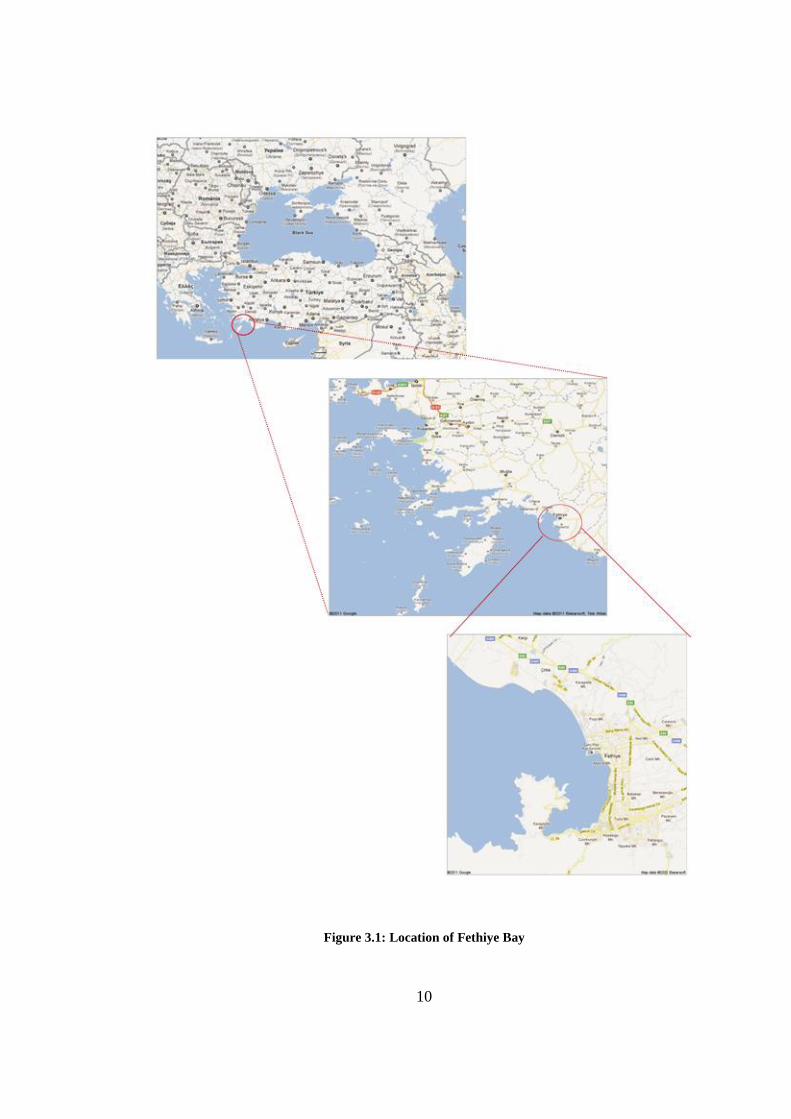
Figure 3.1: Location of Fethiye Bay .......................................................................... 10
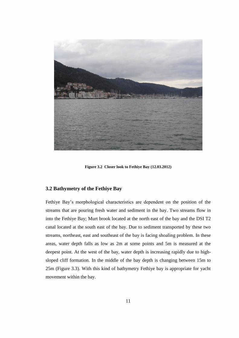
Figure 3.2 Closer look to Fethiye Bay(12.03.2012).................................................. 11
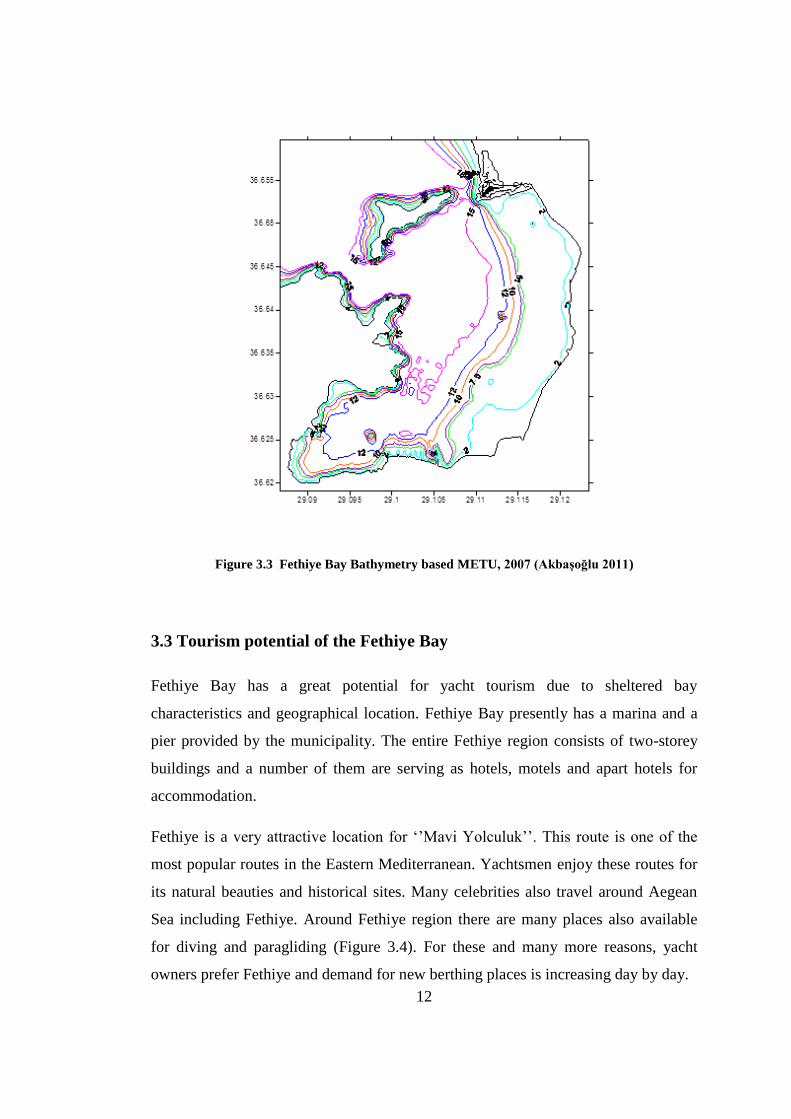
Figure 3.3 Fethiye Bay Bathymetry based METU, 2007 (Akbaşoğlu 2011)............ 12
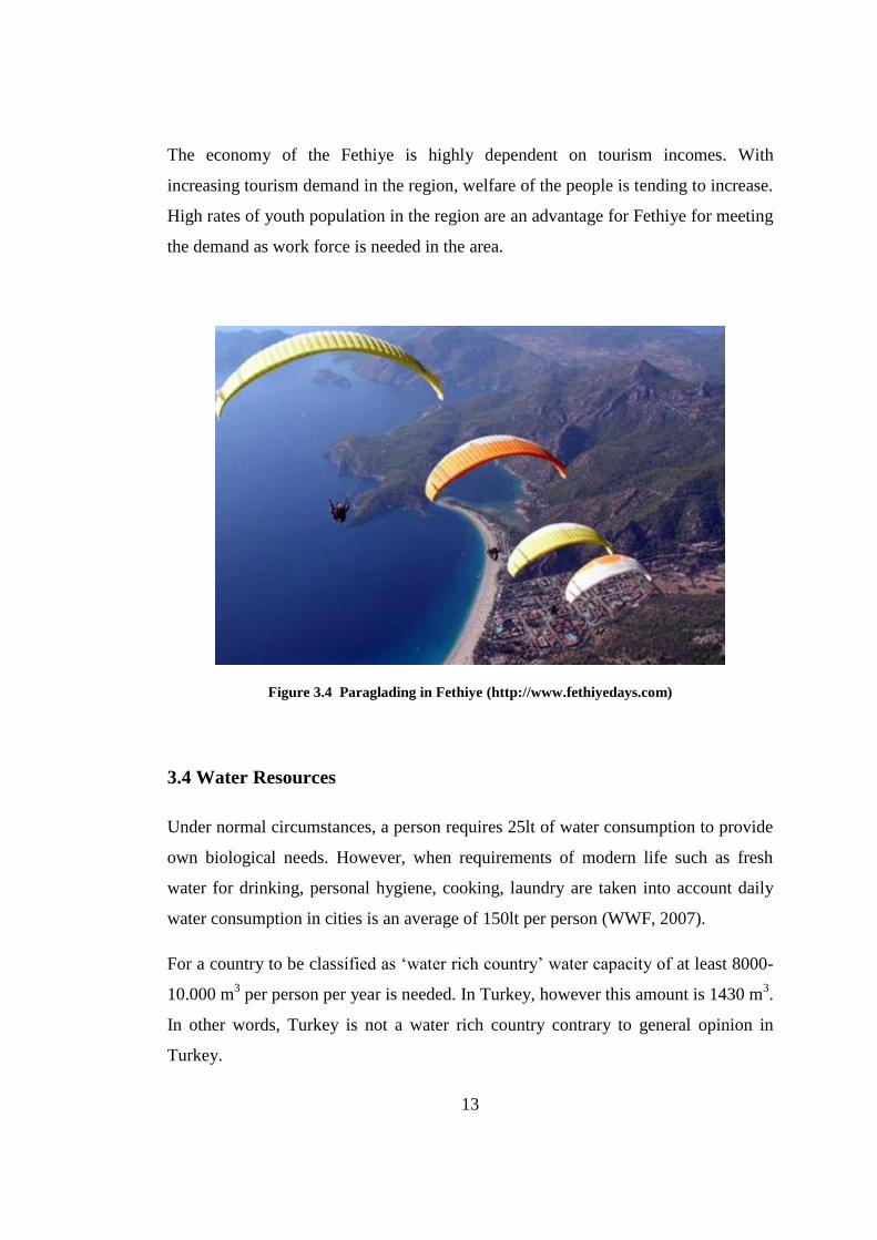
Figure 3.4 Paraglading in Fethiye (http://www.fethiyedays.com) ............................ 13
Figure 3.5 Touristic Facility in Fethiye (12.03.2012) ............................................... 15
Figure 3.6 Unplanned Urbanization in Fethiye (12.032012) .................................... 17
Figure 4.1: Coastline of Fethiye Bay ......................................................................... 29
Figure 4.2: Bathymetry of Fethiye Bay...................................................................... 30
Figure 4.3: Solution cells of Fethiye Bay................................................................... 31
Figure 4.4: Coastline of Fethiye Bay with planned canal .......................................... 32
Figure 4.5: Bathymetry of Fethiye Bay with canal openned ..................................... 33
Figure 4.6: Solution cells of Fethiye Bay with canal opened .................................... 35
Figure 4.7: East side opening cross section location ................................................ 38
Figure 4.8: East side opening depth profile .............................................................. 38
Figure 4.9: West side opening cross section location ............................................... 39
Figure 4.10: West side opening depth profile ........................................................... 39
Figure 4.11: Water circulations for NNW wind direction, 1,5m/s and 5m/s velocity
and 10 hour duration for places close to the bottom of the sea .................................. 40
Figure 4.12: Water circulations for NNW wind direction, 1,5m/s and 5m/s velocity
and 10 hour duration for places close to the sea surface ............................................ 41
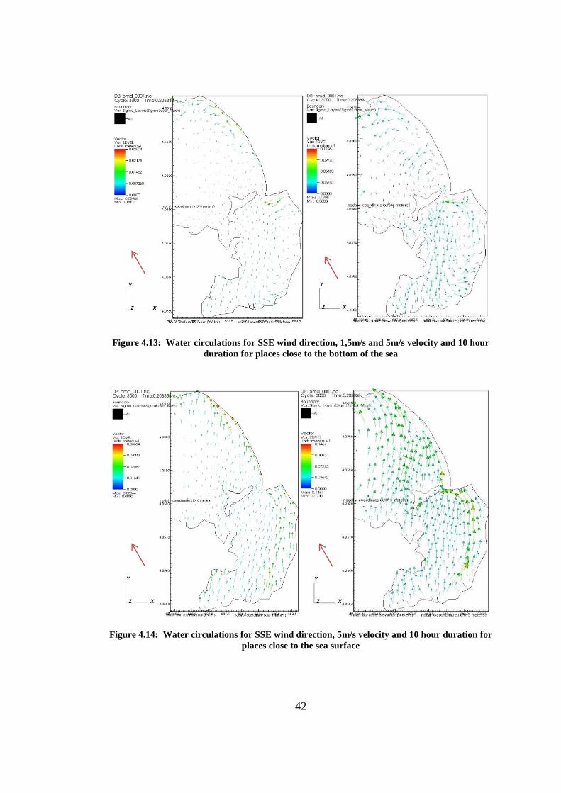
Figure 4.13: Water circulations for SSE wind direction, 1,5m/s and 5m/s velocity
and 10 hour duration for places close to the bottom of the sea .................................. 42
Figure 4.14: Water circulations for SSE wind direction, 5m/s velocity and 10 hour
duration for places close to the sea surface ................................................................ 42
xiv
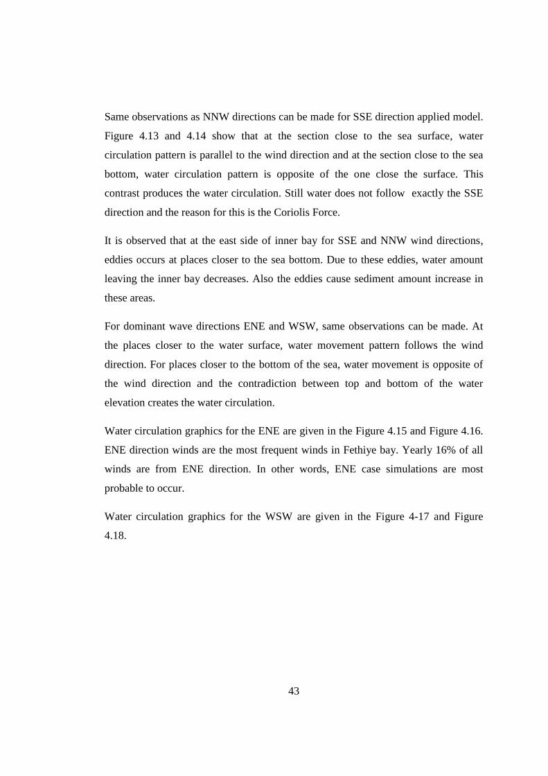
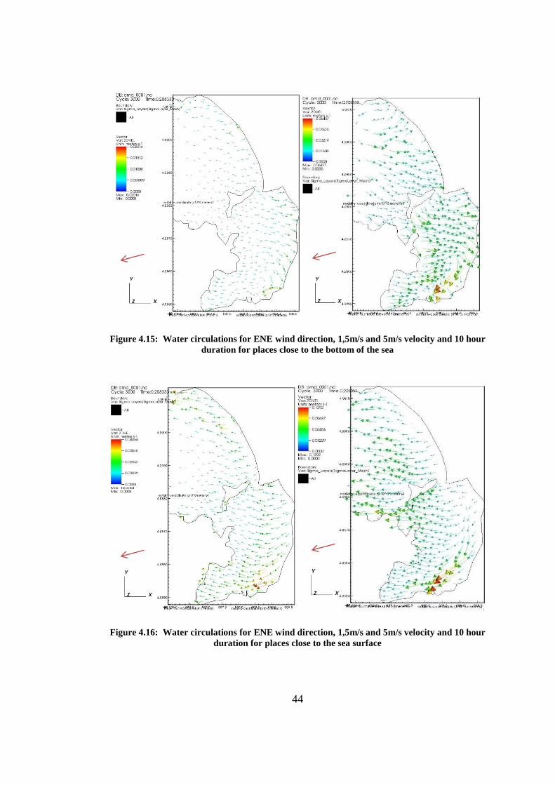
Figure 4.15: Water circulations for ENE wind direction, 1,5m/s and 5m/s velocity
and 10 hour duration for places close to the bottom of the sea .................................. 44
Figure 4.16: Water circulations for ENE wind direction, 1,5m/s and 5m/s velocity
and 10 hour duration for places close to the sea surface ............................................ 44
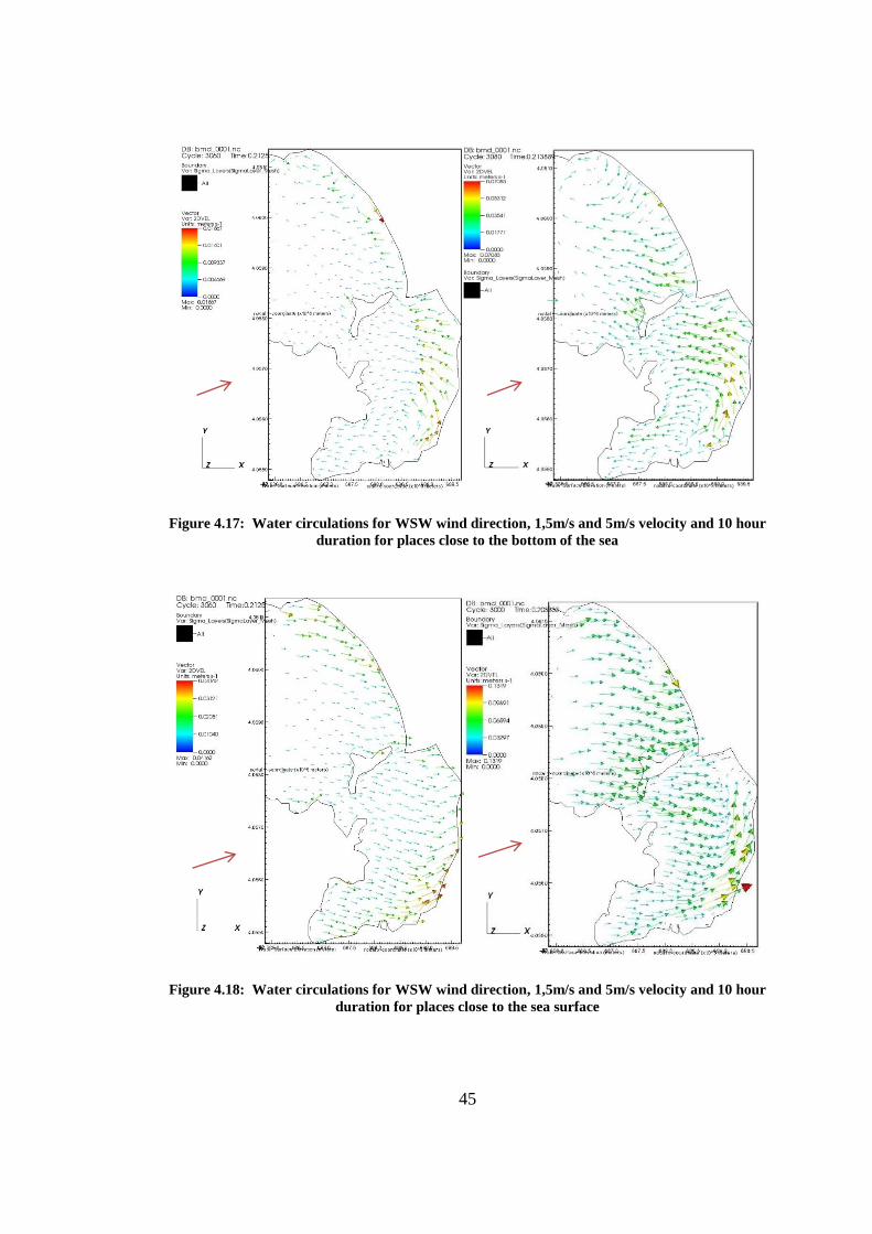
Figure 4.17: Water circulations for WSW wind direction, 1,5m/s and 5m/s velocity
and 10 hour duration for places close to the bottom of the sea .................................. 45
Figure 4.18: Water circulations for WSW wind direction, 1,5m/s and 5m/s velocity
and 10 hour duration for places close to the sea surface ............................................ 45
Figure 4.19: Water depth profile for one representative solution cell case .............. 46
Figure 4.20: Water movement velocity measurement locations ............................... 47
Figure 4.21: Water depth profile for all solution cells along entrence ...................... 48
Figure 4.22: Dredged areas in Fethiye Bay ............................................................... 55
Figure 4.23: Water circulations for NNW wind direction, 1,5m/s and 5m/s velocity
and 10 hour duration for places close to the bottom of the sea for dredged contions 57
Figure 4.24: Water circulations for NNW wind direction, 1,5m/s and5m/s velocity
and 10 hour duration for places close to the sea surface for dredged contions .......... 57
Figure 4.25: Water circulations for SSE wind direction, 1,5m/s and 5m/s velocity
and 10 hour duration for places close to the bottom of the sea for dredged contions 58
Figure 4.26: Water circulations for SSE wind direction, 1,5m/s and 5m/s velocity
and 10 hour duration for places close to the sea surface for dredged contions .......... 58
Figure 4.27: Water circulations for ENE wind direction,1,5m/s and 5m/s velocity
and 10 hour duration for places close to the bottom of the sea for dredged contions 59
Figure 4.28: Water circulations for ENE wind direction, 1,5m/s and 5m/s velocity
and 10 hour duration for places close to the sea surface for dredged contions .......... 59
Figure 4.29: Water circulations for WSW wind direction, 1,5m/s and 5m/s velocity
and 10 hour duration for places close to the bottom of the sea for dredged contions 60
Figure 4.30: Water circulations for WSW wind direction, 1,5m/s and 5m/s velocity
and 10 hour duration for places close to the sea surface for dredged contions .......... 60
Figure 4.31: Cross section for planned canal in Fethiye Bay ................................... 62
Figure 4.32: Cumulative water exchange values for ENE wind direction for all cases
.................................................................................................................................... 64
xv
Figure 4.33: Cumulative water exchange values for WSW wind direction for all
cases ........................................................................................................................... 64
Figure 4.34: Cumulative water exchange values for NNW wind direction for all
cases ........................................................................................................................... 65
Figure 4.35: Cumulative water exchange values for SSE wind direction for all cases
.................................................................................................................................... 65
Figure 5.1: Karagözler location shores ..................................................................... 72
Figure 5.2: Belediye Marina and close shores .......................................................... 72
Figure 5.3: Extracted locations with reasons ............................................................ 73
Figure 5.4: Bay areas for areal approach study ......................................................... 76
Figure 5.5: Coastline of bay used in the areal approach studies ............................... 76
xvi
LIST OF TABLES
TABLES
Table 3.1.a Blowing hours of winds for each direction for Fethiye Meteorological
Station (Akbaşoğlu, 2011). ........................................................................................ 23
Table 3.1.b Blowing hours of winds for each direction for Fethiye Meteorological
Station (Akbaşoğlu, 2011).. ....................................................................................... 24
Table 4.1:Water Exchange volumes for tidal case ..................................................... 36
Table 4.2:Water velocities for ENE wind, west side opening ................................... 48
Table 4.3:Water velocities for ENE wind, west side opening, 1,5 m/s case .............. 49
Table 4.4:Water velocities for ENE wind, west side opening, 5,0m/s case ............... 50
Table 4.5:Water Exchange volumes for ENE wind at the west side , 1,5 m/s case ... 52
Table 4.6:Water Exchange volumes for ENE wind at the west side , 5,0m/s case .... 53
Table 4.7:Water Exchange volumes for selected winds for present situation ........... 54
Table 4.8:Water Exchange volumes for selected winds for dredged case ................. 61
Table 4.9:Water Exchange volumes for selected winds for all cases ........................ 63
Table 5.1: Available Coastal Structures and Berthing places ................................... 74
Table 5.2: Yacht classifications according to their sizes and material .................... 78
Table 5.3: Total wastewater produces by yachts using Fethiye Bay ........................ 79
Table A.1: Circulation for present case, west side opening ....................................... 86
Table A.2: Circulation for present case, east side opening ........................................ 87
Table A.3: Circulation for canal case, canal opening ................................................ 88
Table A.4: Circulation for canal case, west side opening .......................................... 89
Table A.5: Circulation for canal case, east side opening ........................................... 90
Table A.6: Circulation for dredged case, west side opening...................................... 91
Table A.6: Circulation for dredged case, east side opening ....................................... 92
1
CHAPTER 1
INTRODUCTION
Every country wants economic growth, better life standards and to have permanence
in these two aspects. With industrial capacity, agricultural activities and tourism
potentials they are trying their best to achieve this goal. Countries tend toward
whatever their sources are and if possible, they try to increase income from all these
areas. But achieving permanence in growth is not possible by trying to increase
capacities without studying, examining and planning. Pushing limits without
planning causes excessive consumption of natural sources. In progressive aspects,
consumption will affect natural resources irreversibly.
Sustainable development is the solution for conflicts between economic growth and
consumption of natural resources. Sustainable development criteria become very
significant from the time communities realized resources are limited. Considering
that 75% of the human population lives in coastal areas, it is obvious that conflict
between economic growth and consumption puts a big pressure on these regions. As
a solution, integrated coastal zone management should be applied in the most
sensitive areas. An important part of integrated coastal zone management is
determining the carrying capacity in order to set a balance between economic growth
and consumption of local resources in order to achieve sustainable development.
Yacht carrying capacity is the number of yachts that can berth at a place at the same
time without disturbing the environmental balance and ecological diversity of the
place. Yacht carrying capacity of the Fethiye bay is determined in this thesis since
Fethiye is one of the most popular touristic places in Turkey. In addition, the Fethiye
bay is in need for sustainable development of the area.
2
In order to determine the carrying capacity of Fethiye Bay, yachts in the area should
be counted and should be grouped according to their sizes and materials they are
made of. This grouping is needed to calculate the wastewater amount released to the
bay from yachts using the bay yearly. On the other hand, there exists water
circulation in the bay due to the winds, tidal effects and freshwater entrance to the
bay, which clears the bay from these wastewaters.
The water circulation is modeled for three different cases and for four different wind
directions to calculate the water exchange capacity in the bay with the water
circulation modeling program, Finite Volume Coastal Ocean Model - FVCOM. From
the model results it is determined whether Fethiye bay has reached its capacity or
not. The answer to the question if it is possible to accept more yachts in the area or
current use is limit for sustainable development has been searched.
In Chapter 2, literature survey is given. Previous studies on water circulation,
concepts, approaches towards the water circulation modeling and studies related with
the Fethiye region are presented in this chapter.
In Chapter 3, study area is described. Tourism potential, properties of the area, and
wind climate are given in this chapter.
In Chapter 4, circulation analysis and water exchange capacities are calculated for
Fethiye bay under various circumstances.
In Chapter 5, yacht carrying capacity is determined for Fethiye bay by discussing the
wastewater releases and dilution of water in the bay. Moreover, a new approach for
the yacht carrying capacity calculation is proposed.
Finally, in Chapter 6, conclusions are presented and the results are discussed for this
thesis and future recommendations are proposed.
3
CHAPTER 2
LITERATURE SURVEY
Studies related to water circulation for semi-enclosed basins, methodology and
formulations of the studies, numerical models used during the process and case
studies made until now is summarized in this section in the chronological order, to
get information about previous studies made on similar subjects and decide what
method to use in water circulation models for Fethiye bay.
A method is presented for “computing exchange rate and the exchange time of the
water between a coastal basin and the adjacent sea” by Legović (1982). “The
geometry of the cross section of the connecting channels and an approximation of the
current field” are used for calculations. The methodology is applied to a case study
of the Rijeka bay located on the northeast of the Croatia. It is observed that direction
and intensity of the water exchange vary seasonally. Midwinter exchange value is
determined as four times larger than the one calculated in midsummer (Legović,
1982).
In order to precisely predict the flow patterns in semi-enclosed water basins with free
surfaces Li and Zhang (1998) developed a three-dimensional layer-integrated
numerical model. In the model, the turbulence is parameterized using the k-
equations. In the finite difference solution the governing equations are separated into
three parts: “advection, dispersion and propagation”. While the advection equations
are solved by “the four-node minimax-characteristics scheme”, the dispersion
equations are solved by the central difference applications and the Gauss-Seidel
iteration method. The results obtained from the model have been confirmed with the
laboratory data on forced recirculating flow in a physical harbor model. In addition,
4
the model has also been verified with “free recirculating flow in an experiment
channel” (Li et al., 1998).
Kourafalou (2001) studied “semi enclosed regions with river discharge in the
Mediterranean Sea”. In the research, where Po and Axios rivers are examined, “The
development of the river discharges under the influence of the important circulation
forcing mechanisms and under the guidance of the topographic controls” is studied.
River simulations are carried out with the Princeton Ocean Model (POM). “General
basin circulation influence on the discharge structure” is also examined. (Kourafalou,
2001).
Cookman et al. (2001) developed a MATLAB program called STORMSED1.0. The
steady-state, linearized, horizontal momentum equations in the along-shelf and cross-
shelf directions are solved for a linear shoreline given a constant stress, wind and
waves of constant period and amplitude. A numerical relationship between
sedimentation and storms is obtained from the model and it also provides a fast
analytical approach which enables to quantify the sedimentation occurring because
of coastal circulation. (Cookman et al., 2001).
Pietrzak et al. (2002) developed “a three-dimensional hydrostatic model that
combines a generalized vertical coordinate system with an efficient implicit solution
technique for the free surface.” The model enables maintaining high resolution in the
surface and bottom boundary layers. Horizontal diffusion is solved using the
“Smagorinsky formulation” and in the vertical k– turbulence model is used. A
number of tests were conducted using the model. Accordingly, it can be concluded
that “the model is good at simulating shallow nearshore, estuarine flows as well as
large-scale geophysical flows” (Pietrzak et al., 2002).
A 3-dimensional semi-implicit finite difference code is developed by Koçyiğit and
Koçyiğit (2004) for water circulation. In order to take the effect of the vertical
5
acceleration component into account, the non-hydrostatic pressure component and
the conventional sigma coordinate system in the vertical direction were integrated
into the model and the bathymetric changes were considered to be relatively
important physical parameters of the circulation pattern. The developed numerical
model was able to simulate wind-induced circulation in shallow enclosed water
bodies and that “the effect of topography and wind stress on the circulation pattern
was of primary importance while the non-hydrostatic pressure component did not
have much effect” (Koçyiğit et al., 2004).
A “high horizontal resolution 3D hydrodynamic model SYMPHONIE” in a semi-
enclosed bay at the west of the Mediterranean Sea is used by Ulses et al. (2005). In
this study, “specific circulation patterns” and “scales of residence times” are defined.
Typical wind forcing conditions are applied for performing idealized simulations. In
the simulations, “actual conditions of Rhone river discharges” and “meteorological
forcing” is used. Impacts of the adjacent formation, on general circulation are also
taken into consideration. Model results are compared with the observations and
results were satisfactory (Ulses et al., 2005).
Some simulations are made by Zhao et al. (2006) using the unstructured grid, finite-
volume coastal ocean model (FVCOM), to model “tidal motion in Mt. Hope Bay and
Narragansett Bay”. It is observed that FVCOM is able to deal sufficiently with the
“high horizontal resolution”, “irregular coastlines” and “narrow channels”. (Zhao et
al., 2006).
A three dimensional hydrodynamic model called COHERENS is developed by
Marinov et al. (2006) for coastal and shelf seas. Resuspension, contaminant transport
and biological models can be simulated and mesoscale to seasonal scale processes
are resolved by the model. The simulation results for short observations are good.
Currents and water surface elevations during high tide events are observed.
Simulations and measurements gave parallel results. Model results were also parallel
6
with the seasonal trends. Moreover, simulation results fit the detailed salinity and
temperature measurements (Marinov et al., 2006).
In 2007, De Serio et al. examined the hydrodynamic processes of Mar Piccolo which
is a coastal area of the Ionian Sea on the northern side of the Gulf of Taranto. In his
studies, mainly mathematical modeling and field measurements are implemented
with the “baroclinic conditions” and accordingly, the data prepared after the analysis
is input in the 3-D Princeton Ocean Model. Furthermore the analysis accounted for
the following phenomenon; “a simple tidal wave”, “a homogeneous and stationary
wind field” “a constant outflow and vertical stratification of temperature and
salinity”. Correspondingly velocity data obtained with the field surveys are compared
with the results obtained with the numerical model results. (De Serio et al., 2007).
A two-dimensional (2-D) mathematical model is developed to investigate the impact
of wind-induced motion on suspended sediment transport at Beijing’s 13-Ling
Reservoir by Chen et al. (2007). Diagonal Cartesian Method (DCM) with a wetting-
drying dynamic boundary is used in the model to trace variations in the water level.
The simulation results are tested with in situ measurements. The model’s accuracy
and agreement with the actual situation at the reservoir is confirmed by the
measurements. The simulations indicate that wind stress is the key parameter in
suspended sediment transport at Beijing’s 13-Ling Reservoir (Chen et al., 2007).
Sankaranarayanan (2007) applied a three-dimensional “Boundary-Fitted
Hydrodynamic” model (BFHYDRO) to a bay called Buzzards Bay. Tidal forces are
used for the open boundary forcing. For water surface driving, the wind force is used.
Wind and tide-induced circulations are analyzed in detail. It is seen that wind forcing
has a more dominant effect than the tidal forcing in the generation of the barotropic
residual currents in the study location at the end of model simulations
(Sankaranarayanan, 2007).
7
The tidal flooding and tidal drying process are studied for the Satilla River Estuary
by Chen et al. (2008) using the finite-volume coastal ocean model (FVCOM). The
FVCOM numerical model which is implemented by tidal forcing at the open
boundary and river discharge at the upstream end, resulted in a solid conclusion for
the tidal flushing in this estuarine tidal-creek intertidal salt-marsh complex.
Accordingly, the results were acceptable in the aspect of the amplitudes and phases
of the tidal wave, and salinity observed at mooring sites and along hydrographic
transects (Chen et al., 2008).
In the Rías Baixas region (NW Spain), the circulation, in a coastal embayment called
Ría de Muros, was examined by the Iglesias et al. (2008) using the numerical model
of Delft3D-FLOW with the tide, wind and river inflows for the whole study area.
Moreover, current velocity and direction, temperature and salinity of water, river
discharges, wind velocity and direction information for the area are used. “Acoustic
Doppler Current Profiler” and the numerical model gave similar results. Therefore it
is understood that circulations are occurring mainly with the tide. Wind, and river
inflows also have effects but the tidal effect is the most prevailing one for the Ría
hydrodynamics” (Iglesias et al., 2008).
In 2008 for the Danshuei River adjacent to coastal sea in Taiwan, SELFE (a three-
dimensional, time-dependent hydrodynamic model) was implemented for the whole
estuarine system by the Liu et al.. The prevailing factors accounted in the analysis
were the tidal elevations along the open boundary and freshwater flows from the
mainstream and tributaries in the Danshuei River system. The model analysis gave
consistent results with the field data (Liu et al., 2008).
In 2010, Maxam et al. examined a semi-enclosed bay, which is concluded in a fact
that the inner bay water re-circled the reef according to the hydrodynamics of the
bay. Mainly it is observed that the particular forcing conditions of wind and tide can
either increase or decrease the activity of circulations. In other words, the relative
8
importance of driving forces like variation in the wind regime or tides mainly
controls the circulation and bay emanation (Maxam et al., 2010).
A case study is made for Fethiye bay by Akbaşoğlu (2011). FVCOM is used to
process modeling in the semi-enclosed basin. Effects of wind, tide, Coriolis force and
freshwater input are applied while modeling was processed. The results of this study
are yearly water circulation capacity and sediment transported in the Fethiye bay
(Akbaşoğlu, 2011).
9
CHAPTER 3
STUDY AREA GENERAL OVERVIEW
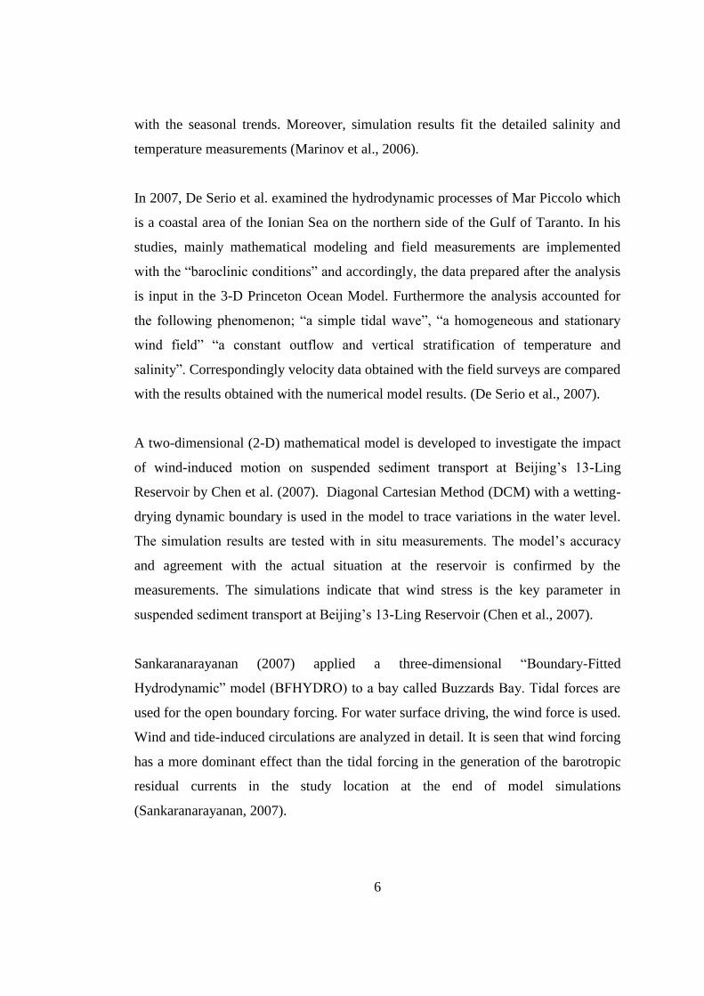
The study area is the Fethiye Bay on the Mediterranean coast of Turkey. The
coordinates of Fethiye Bay are between 36.61640-36.6577
0N and 29.0834
0-
29.12620E. Detailed information about study area, the bathymetry of the area,
tourism potential and wind characteristics is presented in this chapter.
3.1 Fethiye Bay as Study Area
Fethiye Bay is located at the southwest of the Turkey and has a coast neighboring to
the Mediterranean Sea, at the position where Aegean Sea intersects with the
Mediterranean Sea (Figure 3.1).
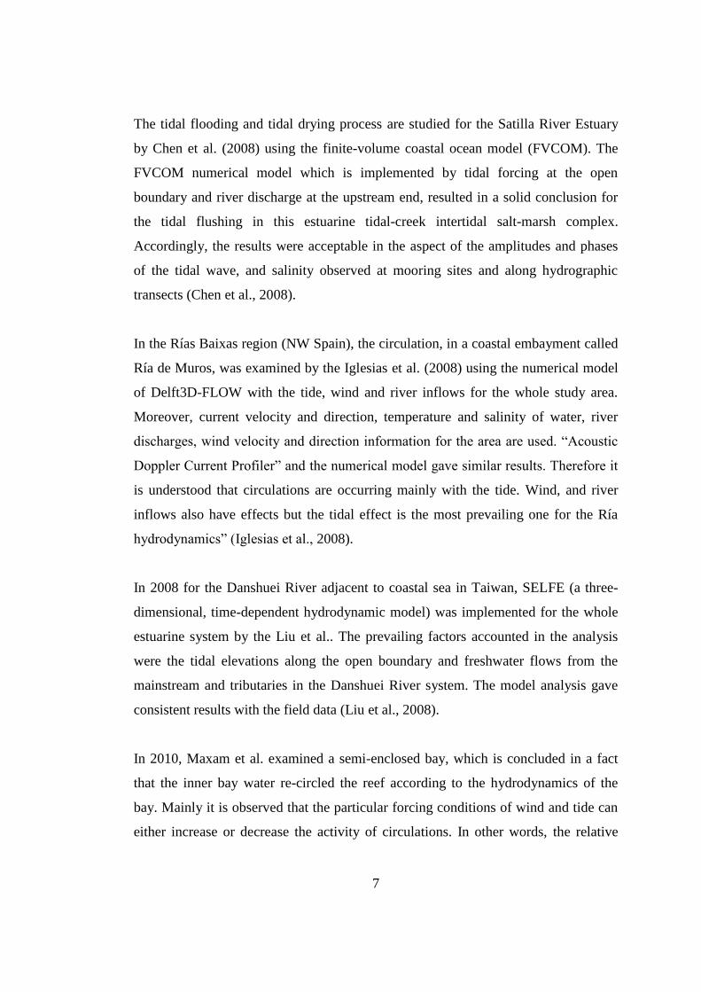
Fethiye is a common visiting place for tourists from all around the world. All kinds
of tourist attractions are available in the Fethiye area. For instance, many yachting
tours have taken Fethiye in their routes and berths along coast and in the marinas
located in the bay (Figure 3.2).
Fethiye area shows typical Eastern Mediterranean climate characteristics, summers
are hot and dry, while winters are warm and rainy. Over 1000 mm rainfall/year is
observed which is above Turkey’s average.
Geology of the region, especially hills within the 2 km from the shoreline, consists of
marl and limestone. The area between the shoreline and these hills is flat and shows
similar geological properties.
Being sheltered naturally due to Şovalye Island is the most important characteristic
of the Fethiye Bay. A large area in the bay is protected from direct impacts of the
open sea.
10
Figure 3.1: Location of Fethiye Bay
11
Figure 3.2 Closer look to Fethiye Bay (12.03.2012)
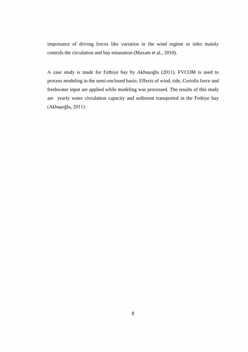
3.2 Bathymetry of the Fethiye Bay
Fethiye Bay’s morphological characteristics are dependent on the position of the
streams that are pouring fresh water and sediment in the bay. Two streams flow in
into the Fethiye Bay; Murt brook located at the north east of the bay and the DSI T2
canal located at the south east of the bay. Due to sediment transported by these two
streams, northeast, east and southeast of the bay is facing shoaling problem. In these
areas, water depth falls as low as 2m at some points and 5m is measured at the
deepest point. At the west of the bay, water depth is increasing rapidly due to high-
sloped cliff formation. In the middle of the bay depth is changing between 15m to
25m (Figure 3.3). With this kind of bathymetry Fethiye bay is appropriate for yacht
movement within the bay.
12
Figure 3.3 Fethiye Bay Bathymetry based METU, 2007 (Akbaşoğlu 2011)
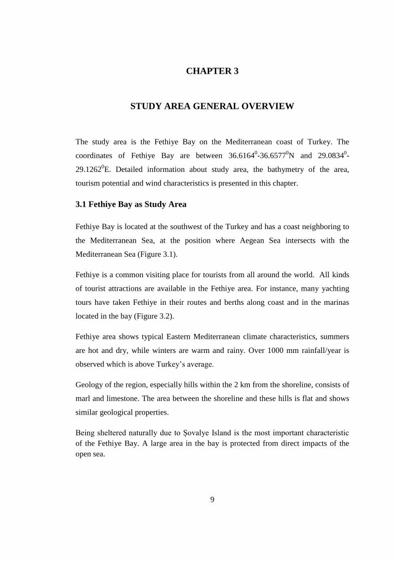
3.3 Tourism potential of the Fethiye Bay
Fethiye Bay has a great potential for yacht tourism due to sheltered bay
characteristics and geographical location. Fethiye Bay presently has a marina and a
pier provided by the municipality. The entire Fethiye region consists of two-storey
buildings and a number of them are serving as hotels, motels and apart hotels for
accommodation.
Fethiye is a very attractive location for ‘’Mavi Yolculuk’’. This route is one of the
most popular routes in the Eastern Mediterranean. Yachtsmen enjoy these routes for
its natural beauties and historical sites. Many celebrities also travel around Aegean
Sea including Fethiye. Around Fethiye region there are many places also available
for diving and paragliding (Figure 3.4). For these and many more reasons, yacht
owners prefer Fethiye and demand for new berthing places is increasing day by day.
13
The economy of the Fethiye is highly dependent on tourism incomes. With
increasing tourism demand in the region, welfare of the people is tending to increase.
High rates of youth population in the region are an advantage for Fethiye for meeting
the demand as work force is needed in the area.
Figure 3.4 Paraglading in Fethiye (http://www.fethiyedays.com)
3.4 Water Resources
Under normal circumstances, a person requires 25lt of water consumption to provide
own biological needs. However, when requirements of modern life such as fresh
water for drinking, personal hygiene, cooking, laundry are taken into account daily
water consumption in cities is an average of 150lt per person (WWF, 2007).
For a country to be classified as ‘water rich country’ water capacity of at least 8000-
10.000 m3 per person per year is needed. In Turkey, however this amount is 1430 m
3.
In other words, Turkey is not a water rich country contrary to general opinion in
Turkey.
14
According to DSI (State Hydraulic Works), Turkey will use own water resources
with an efficiency rate of 100% in next 50 years. Nevertheless, according to WWF
(2007), Turkey’s estimate population will be 80 million people in the year of 2030.
With predicted water capacity of 1.100 m3 per person/year Turkey will have
deficiency in water capacity. With consideration of these data in the near future,
Turkey facing the serious water crisis seems to be inevitable. In order to avoid this
kind of hazard water resources should be managed very carefully.
Even if the water seems to be a renewable resource, actually it is not. With constant,
uncalculated water pollution, usable water resources is polluted and their usage
availability is decreasing day by day. However, with the right treatment, increased
awareness and controlled management, water resources could be the foundation of
the sustainable development for all sectors included.
In order to use water resources in sustainable limits, all the underground and surface
water resources should be identified. Still all the underground water resources and
precipitation amount is not good for usage. Some amount of surface waters and
precipitation is lost due to evaporation and there is an amount of water lost at
underground resources. Besides these, water amount fluctuates through seasons. For
instance, all the precipitation that occurs in autumn and winter joins the underground
water resources in the spring and summer. Under these conditions, especially in the
summer months, when yacht tourism peaks, the sustainable amount of water use
should be specified. This information should be included in the studies which
calculate the number of yachts using a specific area.
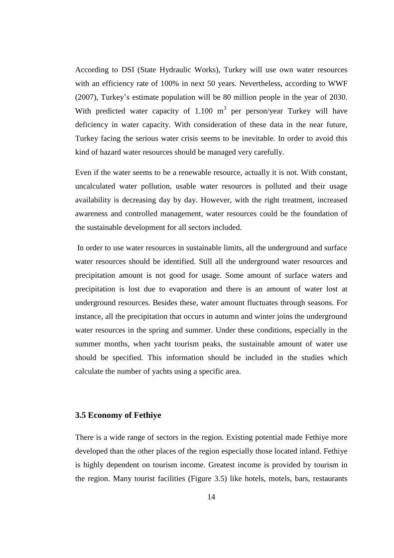
3.5 Economy of Fethiye
There is a wide range of sectors in the region. Existing potential made Fethiye more
developed than the other places of the region especially those located inland. Fethiye
is highly dependent on tourism income. Greatest income is provided by tourism in
the region. Many tourist facilities (Figure 3.5) like hotels, motels, bars, restaurants
15
provide services in the area. This provides many job opportunities for local people
and other people willing to work in the tourism sector. Agriculture is the second
largest economy in the region and half of the population is working in this area.
Tomato is the most produced product of the region. However, tourism income in the
region threatens agricultural landscapes. Some people in the region are willing to
build new places in order to get some income from tourism and this intention causes
agricultural lands to be sold for short-term income by the landowners. Besides
tourism and agriculture, stockbreeding is another important sector. Except these
sectors, there are also people working on apiculture, mining and wood chopping
sectors.
Figure 3.5 Touristic Facility in Fethiye (12.03.2012)
16
3.6 Positive features of Fethiye Bay
In Fethiye region, the tendency of government and municipal is to support the
investments from investors on yacht tourism. These investments are
considered to increase the economic well-being of the region that result in
enliven the economy.
Fethiye has a high rate of youth population that is an advantage for
investments. Knowing that there exists a young workforce encourage the
investors.
Tourism potential is a great advantage for the Fethiye region as mentioned
before.
The region provides rich cultural and historical heritage that is surrounded by
natural beauties. This attracts tourists to choose Fethiye rather than a place
that provides only beaches.
Fethiye is easy to reach by means of air, water and highway. Dalaman airport
is 100km away from the center of Fethiye, which nowadays with better cars
can take less than an hour to drive to reach. Also Fethiye has a long coastline
which is easy to reach by sea. Moreover Fethiye is well connected with
highways and has its own bus terminal.
Fethiye is part of an Eastern Mediterranean yacht chain. Meaning, Fethiye
gets tourists that are travelling worldwide popular places like Greek islands.
Sheltered bay characteristics attract yacht owners to berth their yachts in the
bay. In addition, existing marina and berthing places are advantageous for the
region.
Fethiye region is able to serve for tourists each season of a year. Since the
region shows typical characteristics of Mediterranean climate, winters are
considerably warm and welcoming comparing other cold climates.
There are scientific studies made on the area. These studies will contribute in
the development of the region if the requirements specified in these studies
are applied.
17
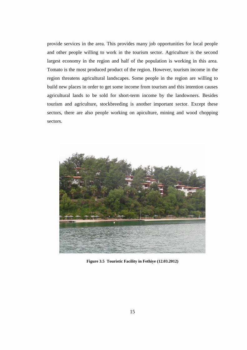
3.7 Negative features of Fethiye Bay
Low education level is a big problem that considers the area. In addition, low
education level can be considered as the source of many man caused
problems in the Fethiye region.
Due to building permits given to irregular and higher storey constructions and
permits given to unregistered plots, irregular developments have occurred.
This irregularity occurs especially on the slopes facing the waterfront, in
order to maintain rant for the participants. Low control, tendencies and not
depending on the regulations of urban areas results in irregular masses
causing visual pollution (Figure 3.6).
There are many institutions working on and presenting opinions about
Fethiye region. However, weak relations and lack of communication between
these institutions decrease the impact of the research on the management of
region.
Figure 3.6 Unplanned Urbanization in Fethiye (12.032012)
18
One of the main problems is the violation of prohibitions and lack of legal
enforcements in various areas. For instance, uneducated people tend to throw
solid wastes anywhere randomly. This might happen to be sea as well. Since
this behavior is not fined, tendency grows to throw solid wastes randomly.
Fethiye is on an earthquake zone 1. There have been many earthquakes in
Fethiye history, some of them caused great damage in the city, and many
lives are lost due to collapse of buildings.
In peak season, which is summer, tourist population is at the highest rate and
parallel to this, sea traffic is very busy.
Excessive usage of the coastal zones causing harm to ecological and
geomorphological texture of the bay.
Economic opportunity causes an excessive population increase due to
immigration from all around the Turkey.
In area, lack of environmental awareness is a problem. There are
communities aware of environmental issues but this is not enough by itself.
Environmental awareness of the public should be increased to accomplish
some goals.
Excessive wood chopping for earning some extra money causes forest
destruction.
The constant conflict of interests on region makes problems stay as unsolved
issues.
19
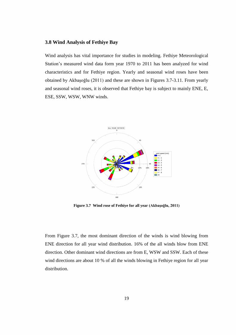
3.8 Wind Analysis of Fethiye Bay
Wind analysis has vital importance for studies in modeling. Fethiye Meteorological
Station’s measured wind data form year 1970 to 2011 has been analyzed for wind
characteristics and for Fethiye region. Yearly and seasonal wind roses have been
obtained by Akbaşoğlu (2011) and these are shown in Figures 3.7-3.11. From yearly
and seasonal wind roses, it is observed that Fethiye bay is subject to mainly ENE, E,
ESE, SSW, WSW, WNW winds.
0
45
90
135
180
225
270
315
0% 4% 8% 12% 16%
wind speed (m/s)
<=1
>1 - 2
>2 - 3
>3 - 4
>4 - 5
>5 - 6
>6 - 7
>7 - 8
>8
ALL YEAR FETHIYE
Figure 3.7 Wind rose of Fethiye for all year (Akbaşoğlu, 2011)
From Figure 3.7, the most dominant direction of the winds is wind blowing from
ENE direction for all year wind distribution. 16% of the all winds blow from ENE
direction. Other dominant wind directions are from E, WSW and SSW. Each of these
wind directions are about 10 % of all the winds blowing in Fethiye region for all year
distribution.
20
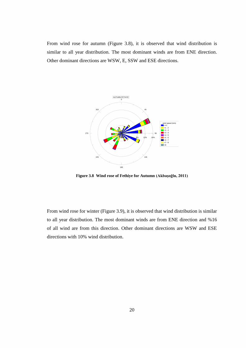
From wind rose for autumn (Figure 3.8), it is observed that wind distribution is
similar to all year distribution. The most dominant winds are from ENE direction.
Other dominant directions are WSW, E, SSW and ESE directions.
0
45
90
135
180
225
270
315
0% 4% 8% 12% 16%
wind speed (m/s)
<=1
>1 - 2
>2 - 3
>3 - 4
>4 - 5
>5 - 6
>6 - 7
>7 - 8
>8
AUTUMN-FETHIYE
Figure 3.8 Wind rose of Fethiye for Autumn (Akbaşoğlu, 2011)
From wind rose for winter (Figure 3.9), it is observed that wind distribution is similar
to all year distribution. The most dominant winds are from ENE direction and %16
of all wind are from this direction. Other dominant directions are WSW and ESE
directions with 10% wind distribution.
21
0
45
90
135
180
225
270
315
0% 4% 8% 12% 16% 20%
wind speed (m/s)
<=1
>1 - 2
>2 - 3
>3 - 4
>4 - 5
>5 - 6
>6 - 7
>7 - 8
>8
WINTER-FETHIYE
Figure 3.9 Wind rose of Fethiye for Winter (Akbaşoğlu, 2011)
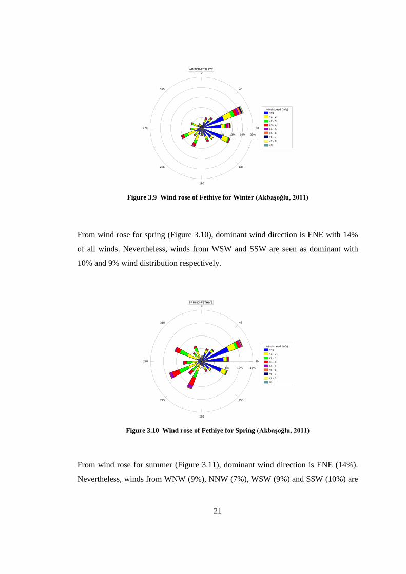
From wind rose for spring (Figure 3.10), dominant wind direction is ENE with 14%
of all winds. Nevertheless, winds from WSW and SSW are seen as dominant with
10% and 9% wind distribution respectively.
0
45
90
135
180
225
270
315
0% 4% 8% 12% 16%
wind speed (m/s)
<=1
>1 - 2
>2 - 3
>3 - 4
>4 - 5
>5 - 6
>6 - 7
>7 - 8
>8
SPRING-FETHIYE
Figure 3.10 Wind rose of Fethiye for Spring (Akbaşoğlu, 2011)
From wind rose for summer (Figure 3.11), dominant wind direction is ENE (14%).
Nevertheless, winds from WNW (9%), NNW (7%), WSW (9%) and SSW (10%) are
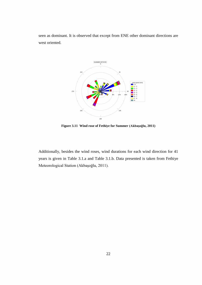
22
seen as dominant. It is observed that except from ENE other dominant directions are
west oriented.
0
45
90
135
180
225
270
315
0% 4% 8% 12% 16%
wind speed (m/s)
<=1
>1 - 2
>2 - 3
>3 - 4
>4 - 5
>5 - 6
>6 - 7
>7 - 8
>8
SUMMER-FETHIYE
Figure 3.11 Wind rose of Fethiye for Summer (Akbaşoğlu, 2011)
Additionally, besides the wind roses, wind durations for each wind direction for 41
years is given in Table 3.1.a and Table 3.1.b. Data presented is taken from Fethiye
Meteorological Station (Akbaşoğlu, 2011).
23
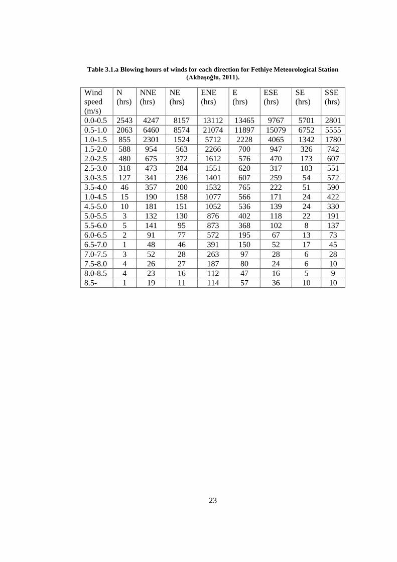
Table 3.1.a Blowing hours of winds for each direction for Fethiye Meteorological Station
(Akbaşoğlu, 2011).
Wind
speed
(m/s)
N
(hrs)
NNE
(hrs)
NE
(hrs)
ENE
(hrs)
E
(hrs)
ESE
(hrs)
SE
(hrs)
SSE
(hrs)
0.0-0.5 2543 4247 8157 13112 13465 9767 5701 2801
0.5-1.0 2063 6460 8574 21074 11897 15079 6752 5555
1.0-1.5 855 2301 1524 5712 2228 4065 1342 1780
1.5-2.0 588 954 563 2266 700 947 326 742
2.0-2.5 480 675 372 1612 576 470 173 607
2.5-3.0 318 473 284 1551 620 317 103 551
3.0-3.5 127 341 236 1401 607 259 54 572
3.5-4.0 46 357 200 1532 765 222 51 590
1.0-4.5 15 190 158 1077 566 171 24 422
4.5-5.0 10 181 151 1052 536 139 24 330
5.0-5.5 3 132 130 876 402 118 22 191
5.5-6.0 5 141 95 873 368 102 8 137
6.0-6.5 2 91 77 572 195 67 13 73
6.5-7.0 1 48 46 391 150 52 17 45
7.0-7.5 3 52 28 263 97 28 6 28
7.5-8.0 4 26 27 187 80 24 6 10
8.0-8.5 4 23 16 112 47 16 5 9
8.5- 1 19 11 114 57 36 10 10
24
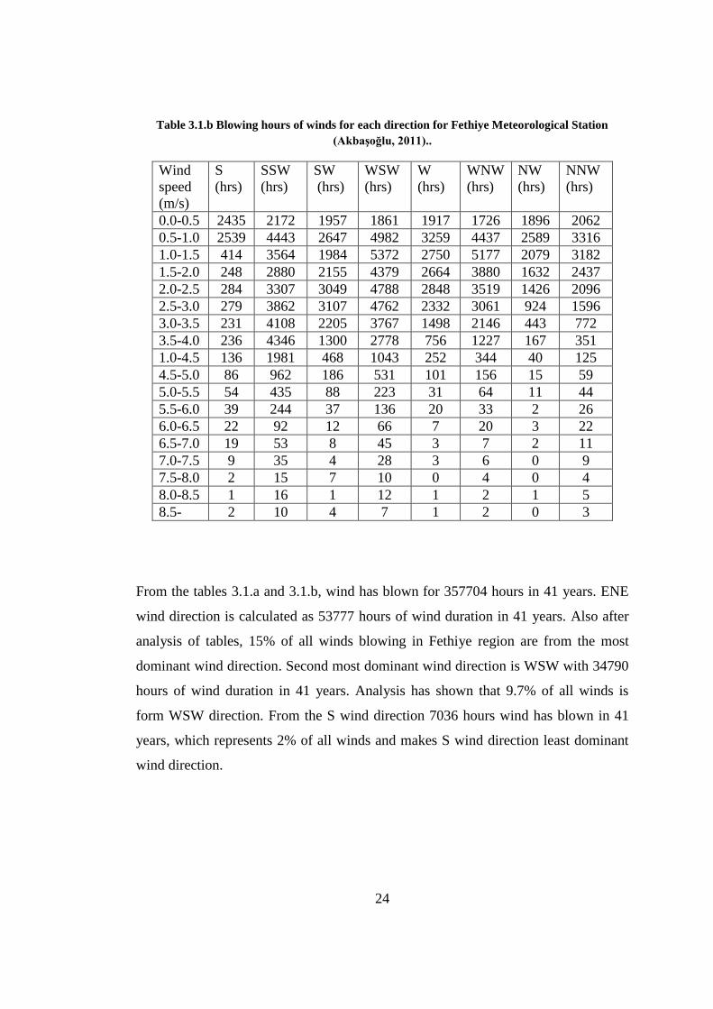
Table 3.1.b Blowing hours of winds for each direction for Fethiye Meteorological Station
(Akbaşoğlu, 2011)..
Wind
speed
(m/s)
S
(hrs)
SSW
(hrs)
SW
(hrs)
WSW
(hrs)
W
(hrs)
WNW
(hrs)
NW
(hrs)
NNW
(hrs)
0.0-0.5 2435 2172 1957 1861 1917 1726 1896 2062
0.5-1.0 2539 4443 2647 4982 3259 4437 2589 3316
1.0-1.5 414 3564 1984 5372 2750 5177 2079 3182
1.5-2.0 248 2880 2155 4379 2664 3880 1632 2437
2.0-2.5 284 3307 3049 4788 2848 3519 1426 2096
2.5-3.0 279 3862 3107 4762 2332 3061 924 1596
3.0-3.5 231 4108 2205 3767 1498 2146 443 772
3.5-4.0 236 4346 1300 2778 756 1227 167 351
1.0-4.5 136 1981 468 1043 252 344 40 125
4.5-5.0 86 962 186 531 101 156 15 59
5.0-5.5 54 435 88 223 31 64 11 44
5.5-6.0 39 244 37 136 20 33 2 26
6.0-6.5 22 92 12 66 7 20 3 22
6.5-7.0 19 53 8 45 3 7 2 11
7.0-7.5 9 35 4 28 3 6 0 9
7.5-8.0 2 15 7 10 0 4 0 4
8.0-8.5 1 16 1 12 1 2 1 5
8.5- 2 10 4 7 1 2 0 3
From the tables 3.1.a and 3.1.b, wind has blown for 357704 hours in 41 years. ENE
wind direction is calculated as 53777 hours of wind duration in 41 years. Also after
analysis of tables, 15% of all winds blowing in Fethiye region are from the most
dominant wind direction. Second most dominant wind direction is WSW with 34790
hours of wind duration in 41 years. Analysis has shown that 9.7% of all winds is
form WSW direction. From the S wind direction 7036 hours wind has blown in 41
years, which represents 2% of all winds and makes S wind direction least dominant
wind direction.

25
For model studies, four different wind directions are chosen to represent the wind
climate of the region. ENE and WSW wind directions are chosen to represents the
dominant wind directions and SSE and NNW wind directions are chosen to represent
non-dominant wind directions. Chosen directions will represent their surrounding
wind directions.
26
CHAPTER 4
WATER EXCHANGE CAPACITY
In this chapter, water circulation studies are proceeded in order to determine water
exchange capacity of Fethiye bay. Water exchange capacity has vital importance in
determination of yacht carrying capacity. Water circulation simulations are carried
out for different case conditions considering the circulations caused by winds, tidal
waves, and fresh water sources. An Unstructured Grid, Finite-Volume Coastal Ocean
Model, shortly FVCOM, is used for these simulations. In the water circulation
simulations, the effect of Coriolis force is included.
4.1 FVCOM
When numerical ocean circulation models are considered, two methods are widely
used in the literature:
The finite-difference method (Blumberg and Mellor, 1987; Blumberg, 1994;
Haidvogel et al., 2000)
The finite-element method (Lynch and Naimie, 1993; Naimie, 1996).
The most basic discrete scheme is the Finite-Difference Method and this method has
the coding efficiency and computational advantage. Finite-Difference Model can fit
in simple coastal areas but is incapable of resolving the highly irregular coastal
geometries like inner shelf (Blumberg 1994; Chen et al. 2001; Chen et al. 2004a).
Arbitrary spatially dependent sized triangular grid meshes are commonly used in this
method, and can provide an accurate fitting of the irregular coastal boundary.
27
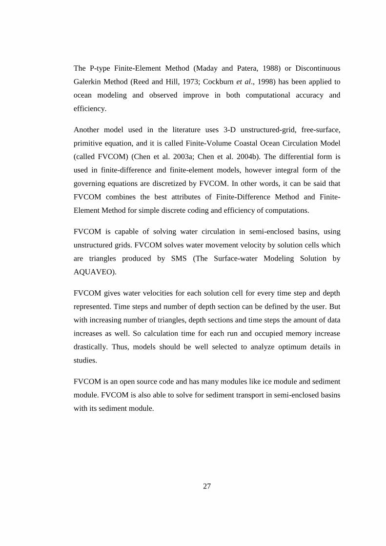
The P-type Finite-Element Method (Maday and Patera, 1988) or Discontinuous
Galerkin Method (Reed and Hill, 1973; Cockburn et al., 1998) has been applied to
ocean modeling and observed improve in both computational accuracy and
efficiency.
Another model used in the literature uses 3-D unstructured-grid, free-surface,
primitive equation, and it is called Finite-Volume Coastal Ocean Circulation Model
(called FVCOM) (Chen et al. 2003a; Chen et al. 2004b). The differential form is
used in finite-difference and finite-element models, however integral form of the
governing equations are discretized by FVCOM. In other words, it can be said that
FVCOM combines the best attributes of Finite-Difference Method and Finite-
Element Method for simple discrete coding and efficiency of computations.
FVCOM is capable of solving water circulation in semi-enclosed basins, using
unstructured grids. FVCOM solves water movement velocity by solution cells which
are triangles produced by SMS (The Surface-water Modeling Solution by
AQUAVEO).
FVCOM gives water velocities for each solution cell for every time step and depth
represented. Time steps and number of depth section can be defined by the user. But
with increasing number of triangles, depth sections and time steps the amount of data
increases as well. So calculation time for each run and occupied memory increase
drastically. Thus, models should be well selected to analyze optimum details in
studies.
FVCOM is an open source code and has many modules like ice module and sediment
module. FVCOM is also able to solve for sediment transport in semi-enclosed basins
with its sediment module.
28
4.2 Data Collection and Modeling Studies
Data collection is basis of the water circulation studies. Data collection and
manipulations are performed to be used as inputs for FVCOM modeling. Fethiye
inner bay’s dimensions are 2.5 km in width and 3.2 km in length and this area is
large enough in order to get appropriate results from modeling.
The municipality informed us about possible future works related to the Bay. Two
future scenarios were most possible ones among others; dredging of northeast and
east of the bay to give more space for yachts and boats using the bay and opening of
a canal at the southwest of the bay assuming that it will increase circulation of the
bay considerably. In light of this information, Fethiye bay is modeled for three
different case scenarios. First case is the present case study without any changes
made to current conditions as a control case. Second case is for dredging of the
northeast and east of the bay. Finally, third case is the opening of a canal at the
southwest of the bay at the Karagözler location.
4.2.1 Coastline Studies Under Present Conditions
FVCOM input data requirements start with coastline data production. QUICKBIRD
2020 image is used with GIS application programs for getting the coastline data and
these data is approved with several checks to control whether coastline data fits to
satellite image (Figure 4.1). Coastline seen on Figure 4.1 is used for present coastline
case studies and dredged case conditions since there is no change in coastline for
proposed dredging case. Coastline data is important for determining the boundaries
detecting sea and land.

29
Figure 4.1: Coastline of Fethiye Bay
4.2.2 Bathymetry Processing For Present Conditions
The second step of the modeling is to develop bathymetric data in reliable resolution
using the measurements. For coastline data produced, bathymetry is needed to be
add on (Figure 4.2). For this application, coastline and bathymetry data should fit
very well. If any discrepancy occurs, solution cells will not be correct which will
30
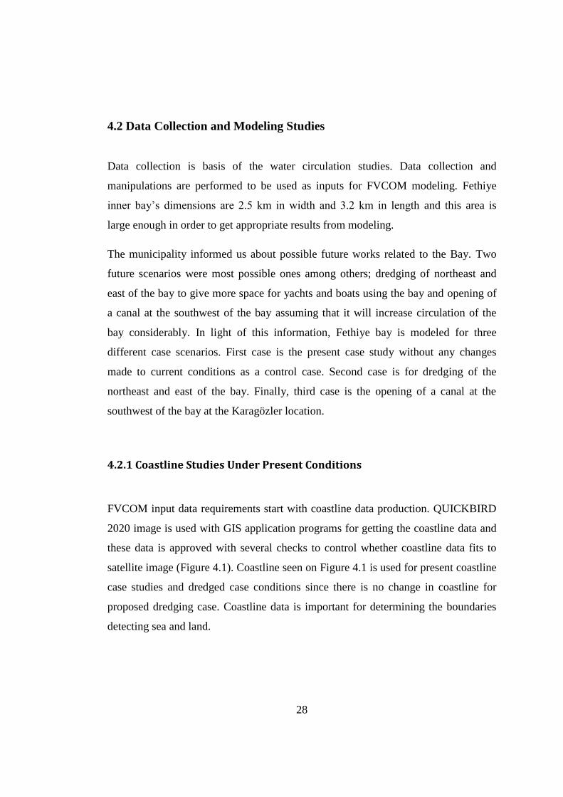
cause errors in the results. The source of bathymetric data is based on recent studies
(METU, 2007). Maximum water depth in the model domain is 90m outside the bay.
However it is 26 m inside Fethiye bay.
Figure 4.2: Bathymetry of Fethiye Bay
31
4.2.3 Triangulation-Solution Cells for Present Conditions
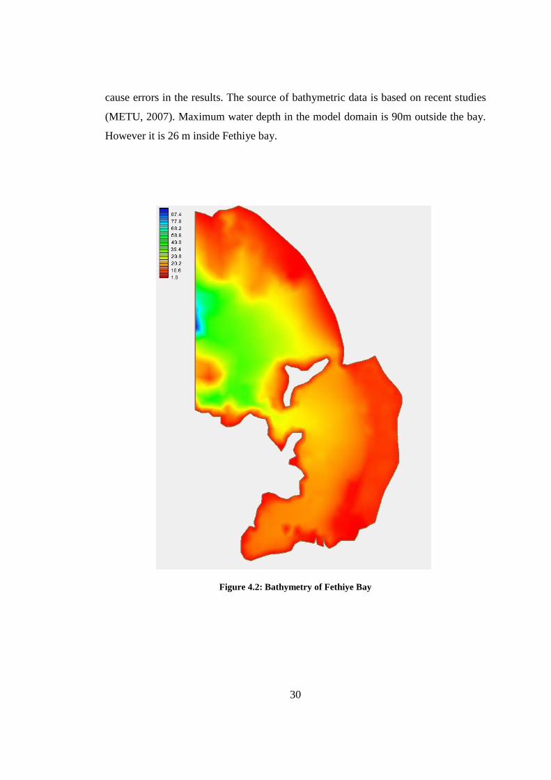
Most important part of bathymetry processing is to make triangulation and obtaining
solution cells for the input to FVCOM. Bathymetry integrated coastline data is
imported to triangulation software SMS. After defining open boundaries and quality
checks to ensure that bathymetry has appropriate triangulation, modeling can be
started. For present case and dredged case studies unstructured gird consisting of 876
nodes and 1576 triangle shaped solution cells is produced (Figure 4.3). Solution cells
have average side length of 150m. Also, depth in each cell is divided in to 5 equal
sigma layers.
Figure 4.3: Solution cells of Fethiye Bay
32
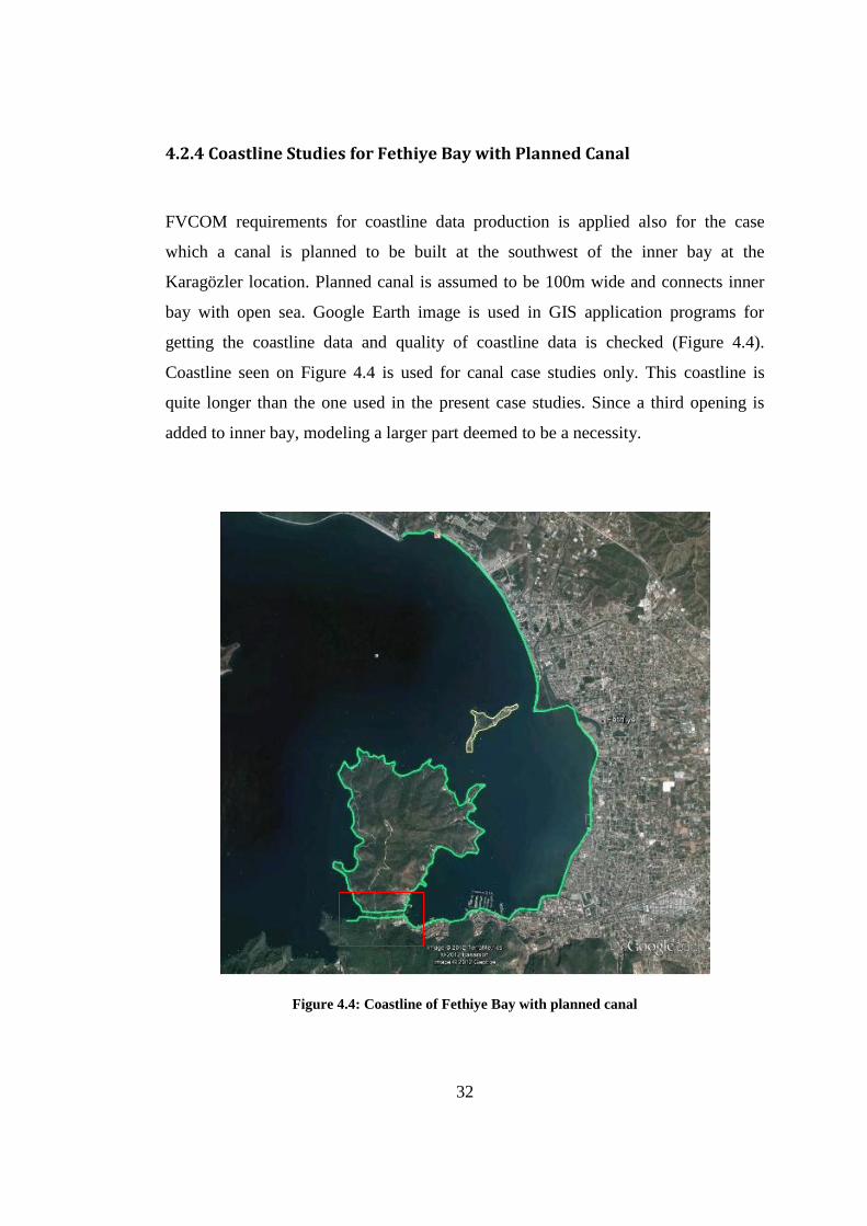
4.2.4 Coastline Studies for Fethiye Bay with Planned Canal
FVCOM requirements for coastline data production is applied also for the case
which a canal is planned to be built at the southwest of the inner bay at the
Karagözler location. Planned canal is assumed to be 100m wide and connects inner
bay with open sea. Google Earth image is used in GIS application programs for
getting the coastline data and quality of coastline data is checked (Figure 4.4).
Coastline seen on Figure 4.4 is used for canal case studies only. This coastline is
quite longer than the one used in the present case studies. Since a third opening is
added to inner bay, modeling a larger part deemed to be a necessity.
Figure 4.4: Coastline of Fethiye Bay with planned canal
33
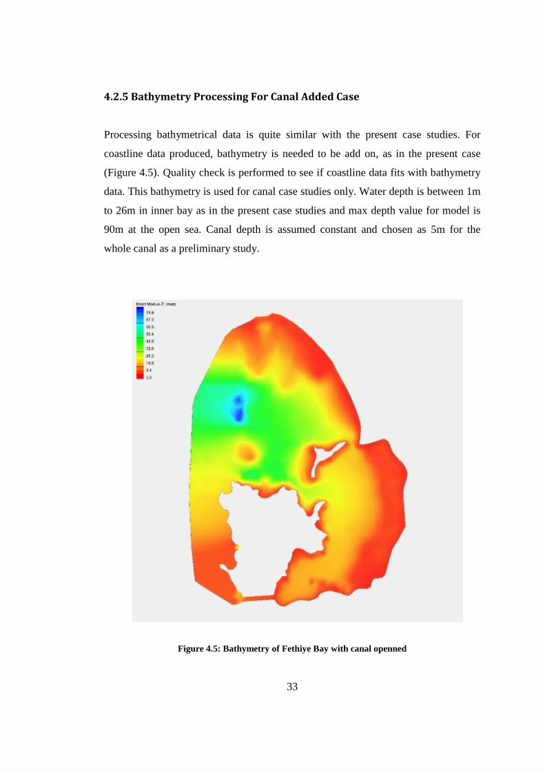
4.2.5 Bathymetry Processing For Canal Added Case
Processing bathymetrical data is quite similar with the present case studies. For
coastline data produced, bathymetry is needed to be add on, as in the present case
(Figure 4.5). Quality check is performed to see if coastline data fits with bathymetry
data. This bathymetry is used for canal case studies only. Water depth is between 1m
to 26m in inner bay as in the present case studies and max depth value for model is
90m at the open sea. Canal depth is assumed constant and chosen as 5m for the
whole canal as a preliminary study.
Figure 4.5: Bathymetry of Fethiye Bay with canal openned

34
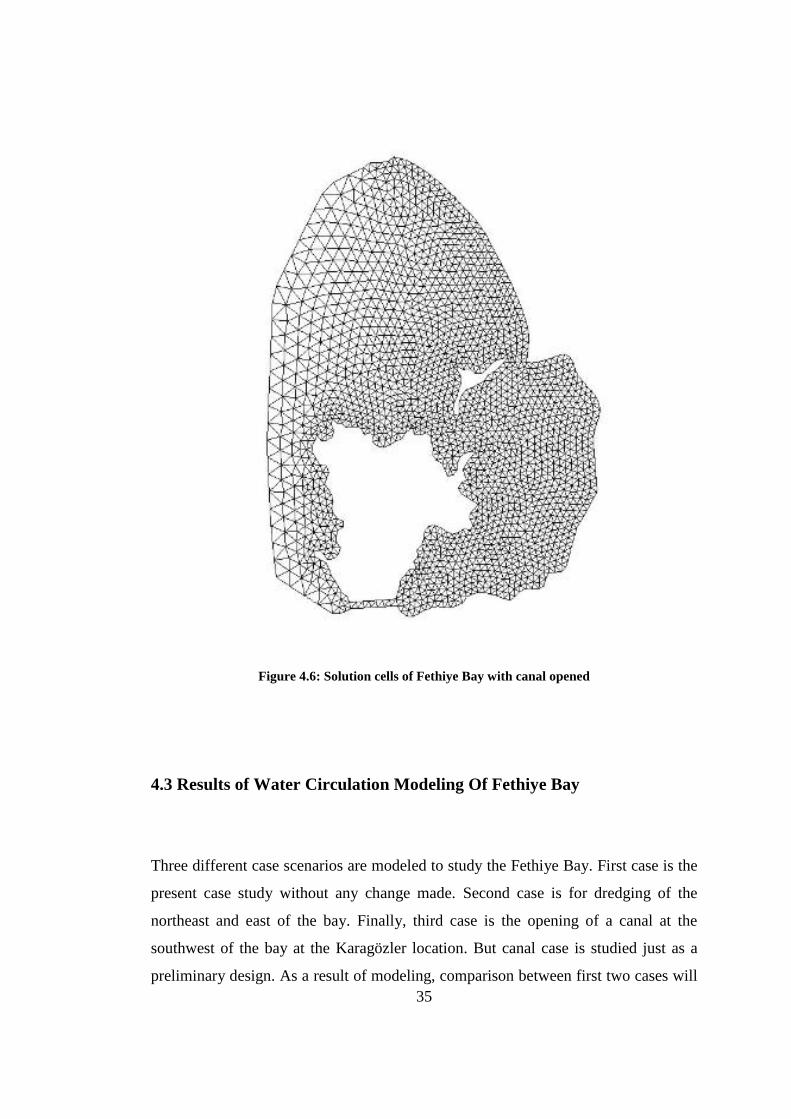
4.2.6 Triangulation-Solution Cells For Canal Added Conditions
Triangulation and preparation of solution cells are part of data preparation for
FVCOM. This procedure needed to done one more time since case data is different
from the present case studies. Bathymetry integrated coastline of canal case data is
imported to triangulation software SMS, similar to present case studies. After
defining open boundaries and making sure that bathymetry is appropriate,
triangulation process has started. For canal added case studies, model is larger than
present case studies model and as a result unstructured grid is visibly larger, it has
more nodes and solution cells. Model consists of 1934 nodes and 3564 triangle
shaped solution cells (Figure 4.6). It could be seen that triangle are smaller than then
the ones in present case and the dredged case studies and this causes unstructured
grid data getting larger. As data gets larger calculation time of FVCOM elongates as
well. Even though calculation time elongates, getting most accurate result is
important for canal case since opening a canal needs a large amount of investment.
So detailed solution should be used for most accurate results. Solution cells have
average side length of 100m which also indicates that triangles are smaller than the
ones in present case studies. Depth in each cell is divided in to 5 equal segments as in
the present case studies.
35
Figure 4.6: Solution cells of Fethiye Bay with canal opened
4.3 Results of Water Circulation Modeling Of Fethiye Bay
Three different case scenarios are modeled to study the Fethiye Bay. First case is the
present case study without any change made. Second case is for dredging of the
northeast and east of the bay. Finally, third case is the opening of a canal at the
southwest of the bay at the Karagözler location. But canal case is studied just as a
preliminary design. As a result of modeling, comparison between first two cases will
36
be made. For comparing the results, simulations are made under same weather
(temperature and wind) and sea conditions (salinity) but with different bathymetrical
properties for same time durations. For four different wind directions, the model was
run. These directions are NNW, SSE, ENE and WSW. For all directions, winds with
5m/s and 1,5m/s velocities and 10 hours duration are chosen. ENE and WSW are
most dominant wind directions for Fethiye bay. For low wind velocities, 1,5m/s
studies is assumed as representative and 5,0m/s studies is assumed as representative
for high velocity winds in the analysis for yearly water exchange capacity. Also, in
addition to the wind; tidal conditions are studied for Fethiye bay. Tidal case is
modeled for 10 hours duration and for same salinity and temperature as wind cases.
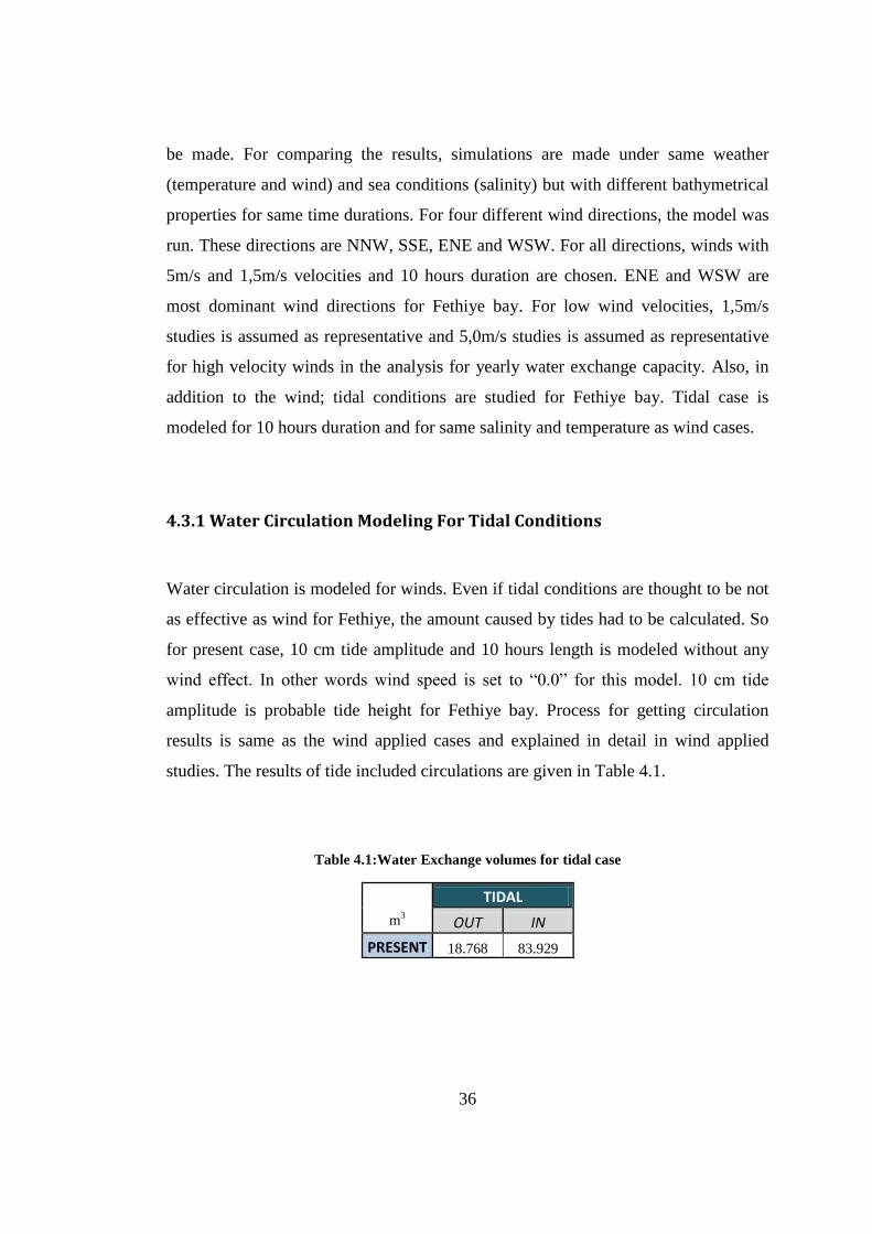
4.3.1 Water Circulation Modeling For Tidal Conditions
Water circulation is modeled for winds. Even if tidal conditions are thought to be not
as effective as wind for Fethiye, the amount caused by tides had to be calculated. So
for present case, 10 cm tide amplitude and 10 hours length is modeled without any
wind effect. In other words wind speed is set to “0.0” for this model. 10 cm tide
amplitude is probable tide height for Fethiye bay. Process for getting circulation
results is same as the wind applied cases and explained in detail in wind applied
studies. The results of tide included circulations are given in Table 4.1.
Table 4.1:Water Exchange volumes for tidal case
TIDAL
m3 OUT IN
PRESENT 18.768 83.929
37
As seen on Table 4.1, effect of tide for Fethiye bay is considerably small. When
results of tidal effects and wind effects are compared, it is seen that tide effect is not
significant so can be ignored. As a result, the rest of the modeling studies did not
include tide parameter.
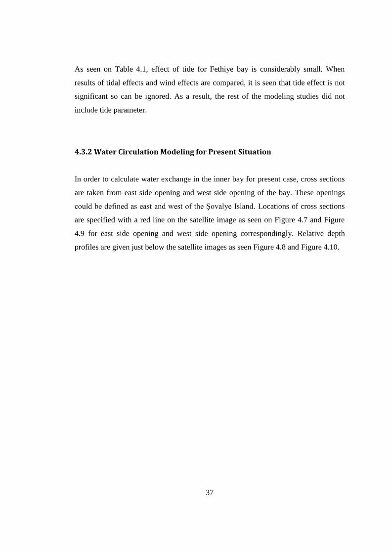
4.3.2 Water Circulation Modeling for Present Situation
In order to calculate water exchange in the inner bay for present case, cross sections
are taken from east side opening and west side opening of the bay. These openings
could be defined as east and west of the Şovalye Island. Locations of cross sections
are specified with a red line on the satellite image as seen on Figure 4.7 and Figure
4.9 for east side opening and west side opening correspondingly. Relative depth
profiles are given just below the satellite images as seen Figure 4.8 and Figure 4.10.
38
Figure 4.7: East side opening cross section location
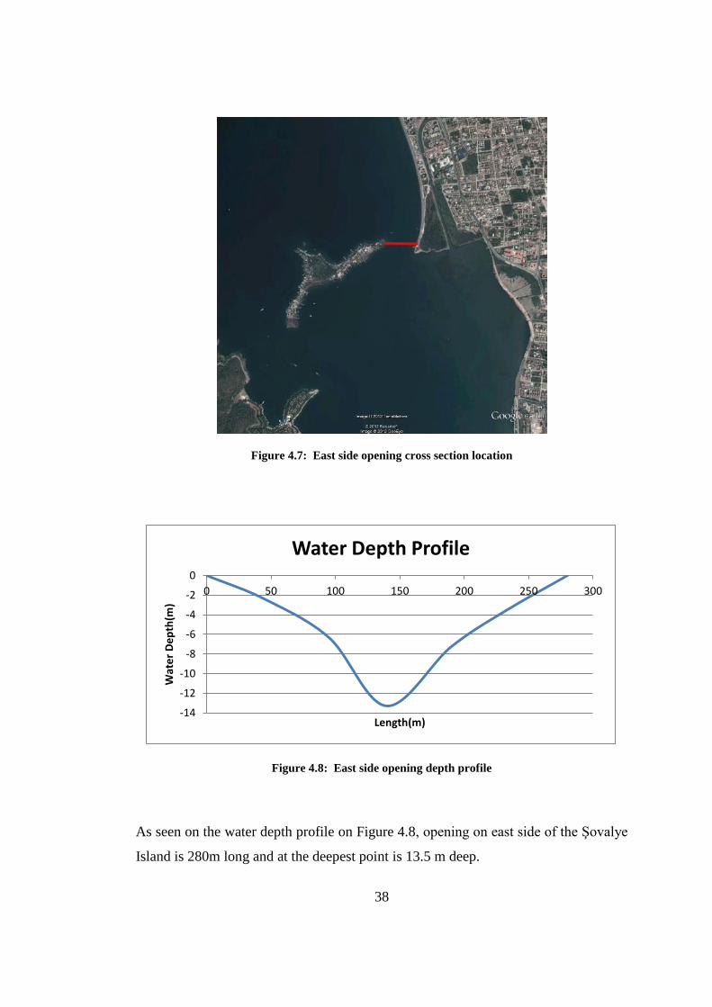
Figure 4.8: East side opening depth profile
As seen on the water depth profile on Figure 4.8, opening on east side of the Şovalye
Island is 280m long and at the deepest point is 13.5 m deep.
-14
-12
-10
-8
-6
-4
-2
0
0 50 100 150 200 250 300
Wat
er
De
pth
(m)
Length(m)
Water Depth Profile
39
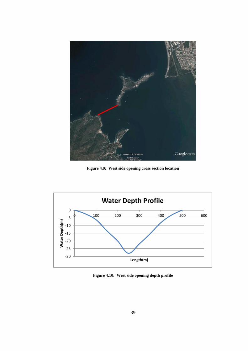
Figure 4.9: West side opening cross section location
Figure 4.10: West side opening depth profile
-30
-25
-20
-15
-10
-5
0
0 100 200 300 400 500 600
Wat
er
De
pth
(m)
Length(m)
Water Depth Profile
40
As seen on the water depth profile on Figure 4.10, opening on west side of the
Şovalye Island is quite larger than then opening on the east side. Cross section is
500m long and at the deepest point is 28 m deep.
Time variable water circulation is modeled for Fethiye bay under different wind
conditions. Four different wind directions are chosen to be applied on the model.
Two cases are chosen to be winds from dominant directions as ENE and WSW. And
other two wind direction are chosen to be from less occurring directions as NNW and
SSE.
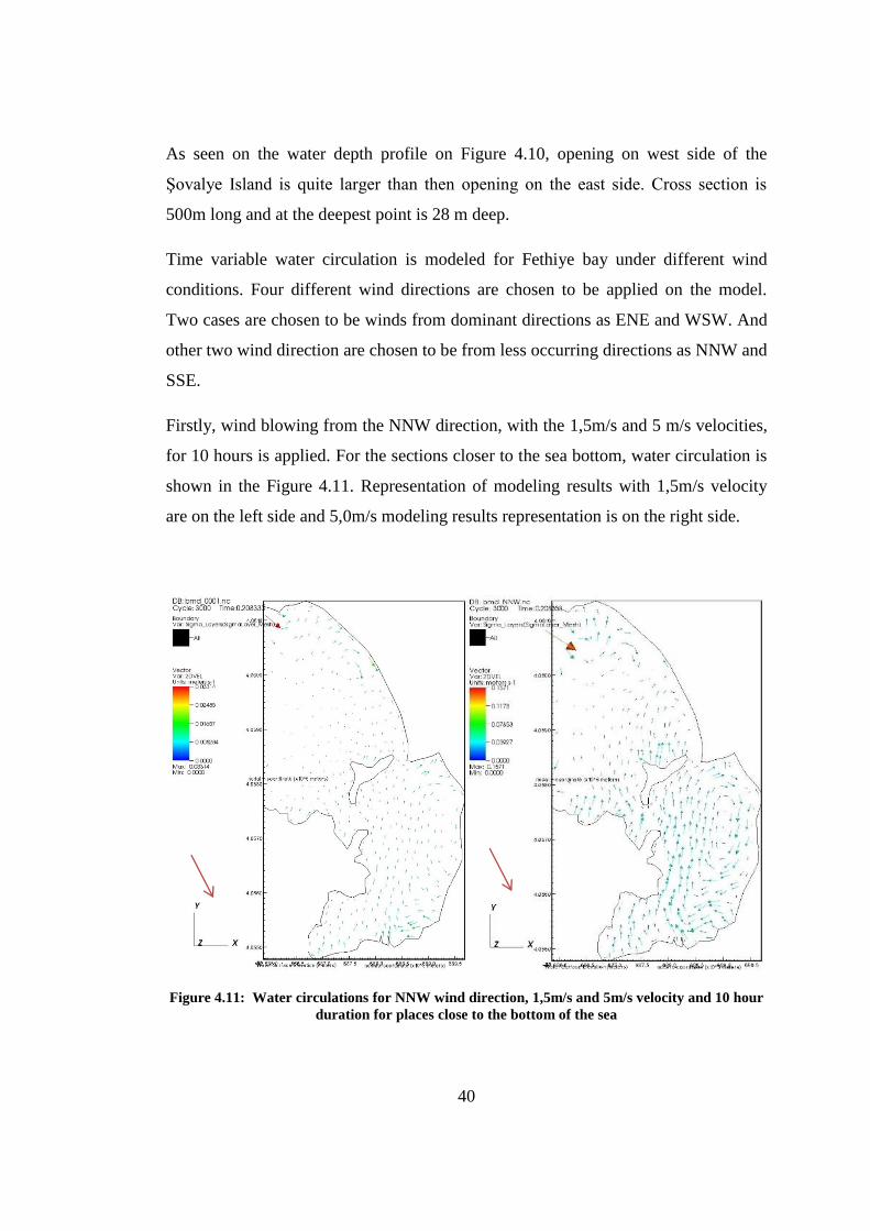
Firstly, wind blowing from the NNW direction, with the 1,5m/s and 5 m/s velocities,
for 10 hours is applied. For the sections closer to the sea bottom, water circulation is
shown in the Figure 4.11. Representation of modeling results with 1,5m/s velocity
are on the left side and 5,0m/s modeling results representation is on the right side.
Figure 4.11: Water circulations for NNW wind direction, 1,5m/s and 5m/s velocity and 10 hour
duration for places close to the bottom of the sea
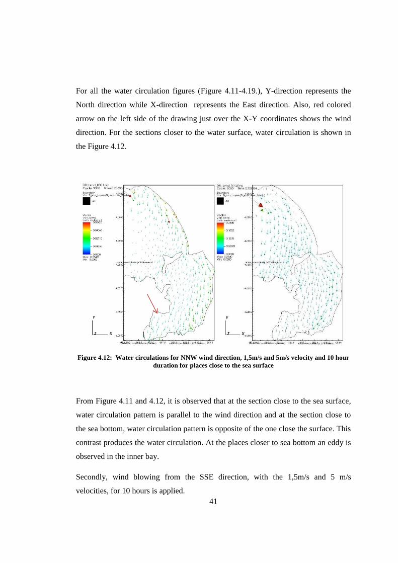
41
For all the water circulation figures (Figure 4.11-4.19.), Y-direction represents the
North direction while X-direction represents the East direction. Also, red colored
arrow on the left side of the drawing just over the X-Y coordinates shows the wind
direction. For the sections closer to the water surface, water circulation is shown in
the Figure 4.12.
Figure 4.12: Water circulations for NNW wind direction, 1,5m/s and 5m/s velocity and 10 hour
duration for places close to the sea surface
From Figure 4.11 and 4.12, it is observed that at the section close to the sea surface,
water circulation pattern is parallel to the wind direction and at the section close to
the sea bottom, water circulation pattern is opposite of the one close the surface. This
contrast produces the water circulation. At the places closer to sea bottom an eddy is
observed in the inner bay.
Secondly, wind blowing from the SSE direction, with the 1,5m/s and 5 m/s
velocities, for 10 hours is applied.
42
Figure 4.13: Water circulations for SSE wind direction, 1,5m/s and 5m/s velocity and 10 hour
duration for places close to the bottom of the sea
Figure 4.14: Water circulations for SSE wind direction, 5m/s velocity and 10 hour duration for
places close to the sea surface
43
Same observations as NNW directions can be made for SSE direction applied model.
Figure 4.13 and 4.14 show that at the section close to the sea surface, water
circulation pattern is parallel to the wind direction and at the section close to the sea
bottom, water circulation pattern is opposite of the one close the surface. This
contrast produces the water circulation. Still water does not follow exactly the SSE
direction and the reason for this is the Coriolis Force.
It is observed that at the east side of inner bay for SSE and NNW wind directions,
eddies occurs at places closer to the sea bottom. Due to these eddies, water amount
leaving the inner bay decreases. Also the eddies cause sediment amount increase in
these areas.
For dominant wave directions ENE and WSW, same observations can be made. At
the places closer to the water surface, water movement pattern follows the wind
direction. For places closer to the bottom of the sea, water movement is opposite of
the wind direction and the contradiction between top and bottom of the water
elevation creates the water circulation.
Water circulation graphics for the ENE are given in the Figure 4.15 and Figure 4.16.
ENE direction winds are the most frequent winds in Fethiye bay. Yearly 16% of all
winds are from ENE direction. In other words, ENE case simulations are most
probable to occur.
Water circulation graphics for the WSW are given in the Figure 4-17 and Figure
4.18.
44
Figure 4.15: Water circulations for ENE wind direction, 1,5m/s and 5m/s velocity and 10 hour
duration for places close to the bottom of the sea
Figure 4.16: Water circulations for ENE wind direction, 1,5m/s and 5m/s velocity and 10 hour
duration for places close to the sea surface
45
Figure 4.17: Water circulations for WSW wind direction, 1,5m/s and 5m/s velocity and 10 hour
duration for places close to the bottom of the sea
Figure 4.18: Water circulations for WSW wind direction, 1,5m/s and 5m/s velocity and 10 hour
duration for places close to the sea surface
46
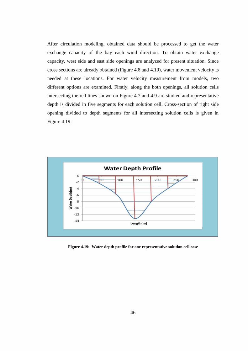
After circulation modeling, obtained data should be processed to get the water
exchange capacity of the bay each wind direction. To obtain water exchange
capacity, west side and east side openings are analyzed for present situation. Since
cross sections are already obtained (Figure 4.8 and 4.10), water movement velocity is
needed at these locations. For water velocity measurement from models, two
different options are examined. Firstly, along the both openings, all solution cells
intersecting the red lines shown on Figure 4.7 and 4.9 are studied and representative
depth is divided in five segments for each solution cell. Cross-section of right side
opening divided to depth segments for all intersecting solution cells is given in
Figure 4.19.
Figure 4.19: Water depth profile for one representative solution cell case
47
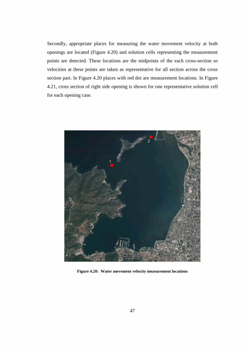
Secondly, appropriate places for measuring the water movement velocity at both
openings are located (Figure 4.20) and solution cells representing the measurement
points are detected. These locations are the midpoints of the each cross-section so
velocities at these points are taken as representative for all section across the cross
section part. In Figure 4.20 places with red dot are measurement locations. In Figure
4.21, cross section of right side opening is shown for one representative solution cell
for each opening case.
Figure 4.20: Water movement velocity measurement locations
48
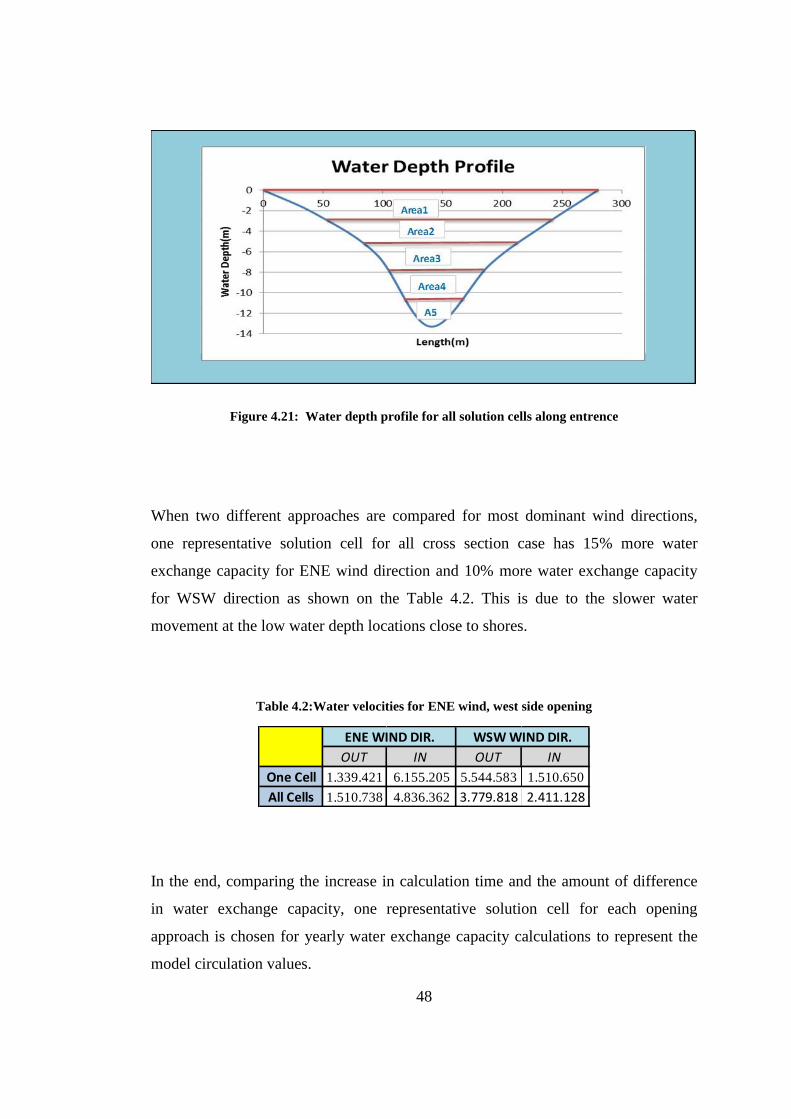
Figure 4.21: Water depth profile for all solution cells along entrence
When two different approaches are compared for most dominant wind directions,
one representative solution cell for all cross section case has 15% more water
exchange capacity for ENE wind direction and 10% more water exchange capacity
for WSW direction as shown on the Table 4.2. This is due to the slower water
movement at the low water depth locations close to shores.
Table 4.2:Water velocities for ENE wind, west side opening
In the end, comparing the increase in calculation time and the amount of difference
in water exchange capacity, one representative solution cell for each opening
approach is chosen for yearly water exchange capacity calculations to represent the
model circulation values.
OUT IN OUT IN
One Cell 1.339.421 6.155.205 5.544.583 1.510.650
All Cells 1.510.738 4.836.362 3.779.818 2.411.128
ENE WIND DIR. WSW WIND DIR.
49
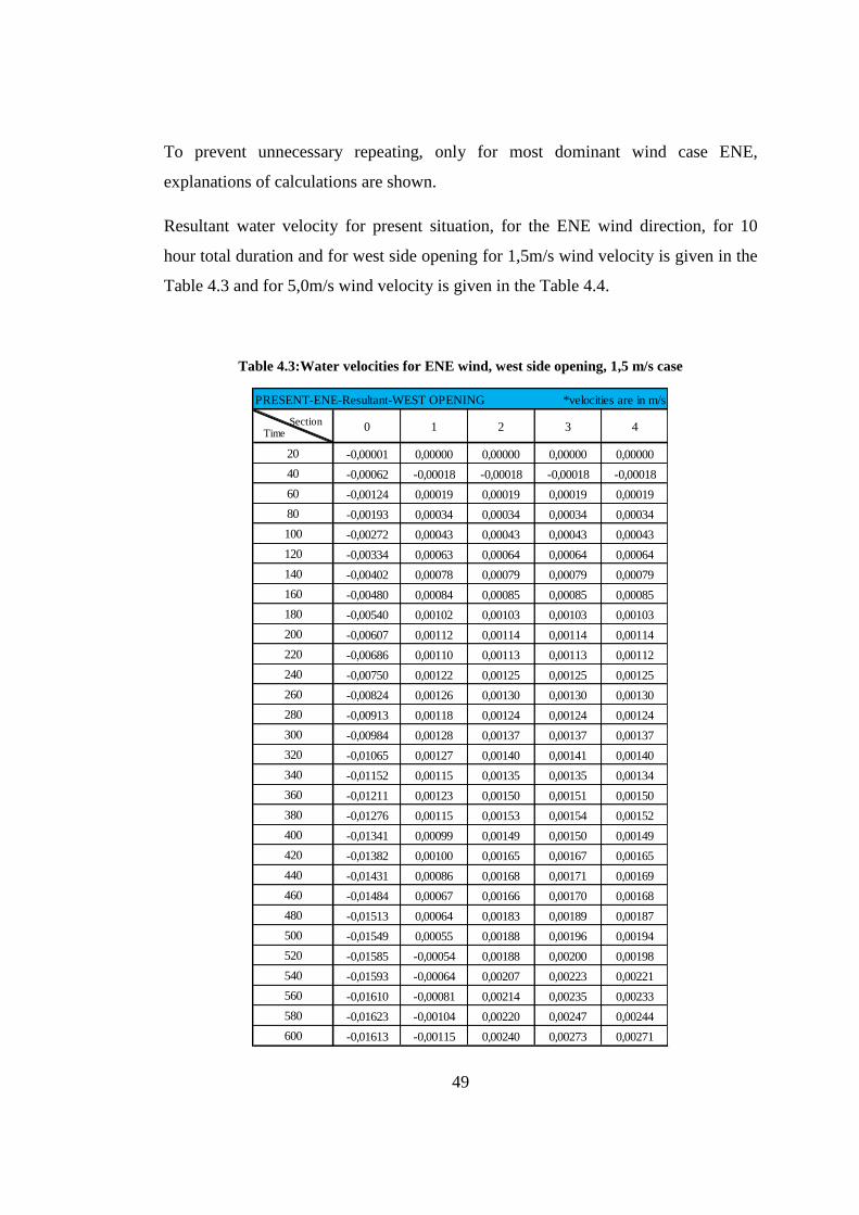
To prevent unnecessary repeating, only for most dominant wind case ENE,
explanations of calculations are shown.
Resultant water velocity for present situation, for the ENE wind direction, for 10
hour total duration and for west side opening for 1,5m/s wind velocity is given in the
Table 4.3 and for 5,0m/s wind velocity is given in the Table 4.4.
Table 4.3:Water velocities for ENE wind, west side opening, 1,5 m/s case
PRESENT-ENE-Resultant-WEST OPENING *velocities are in m/s
Time Section
0 1 2 3 4
20 -0,00001 0,00000 0,00000 0,00000 0,00000
40 -0,00062 -0,00018 -0,00018 -0,00018 -0,00018
60 -0,00124 0,00019 0,00019 0,00019 0,00019
80 -0,00193 0,00034 0,00034 0,00034 0,00034
100 -0,00272 0,00043 0,00043 0,00043 0,00043
120 -0,00334 0,00063 0,00064 0,00064 0,00064
140 -0,00402 0,00078 0,00079 0,00079 0,00079
160 -0,00480 0,00084 0,00085 0,00085 0,00085
180 -0,00540 0,00102 0,00103 0,00103 0,00103
200 -0,00607 0,00112 0,00114 0,00114 0,00114
220 -0,00686 0,00110 0,00113 0,00113 0,00112
240 -0,00750 0,00122 0,00125 0,00125 0,00125
260 -0,00824 0,00126 0,00130 0,00130 0,00130
280 -0,00913 0,00118 0,00124 0,00124 0,00124
300 -0,00984 0,00128 0,00137 0,00137 0,00137
320 -0,01065 0,00127 0,00140 0,00141 0,00140
340 -0,01152 0,00115 0,00135 0,00135 0,00134
360 -0,01211 0,00123 0,00150 0,00151 0,00150
380 -0,01276 0,00115 0,00153 0,00154 0,00152
400 -0,01341 0,00099 0,00149 0,00150 0,00149
420 -0,01382 0,00100 0,00165 0,00167 0,00165
440 -0,01431 0,00086 0,00168 0,00171 0,00169
460 -0,01484 0,00067 0,00166 0,00170 0,00168
480 -0,01513 0,00064 0,00183 0,00189 0,00187
500 -0,01549 0,00055 0,00188 0,00196 0,00194
520 -0,01585 -0,00054 0,00188 0,00200 0,00198
540 -0,01593 -0,00064 0,00207 0,00223 0,00221
560 -0,01610 -0,00081 0,00214 0,00235 0,00233
580 -0,01623 -0,00104 0,00220 0,00247 0,00244
600 -0,01613 -0,00115 0,00240 0,00273 0,00271
50
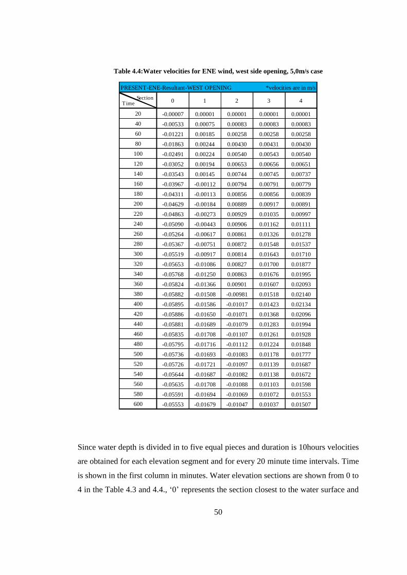
Table 4.4:Water velocities for ENE wind, west side opening, 5,0m/s case
Since water depth is divided in to five equal pieces and duration is 10hours velocities
are obtained for each elevation segment and for every 20 minute time intervals. Time
is shown in the first column in minutes. Water elevation sections are shown from 0 to
4 in the Table 4.3 and 4.4., ‘0’ represents the section closest to the water surface and
PRESENT-ENE-Resultant-WEST OPENING *velocities are in m/s
Time Section
0 1 2 3 4
20 -0.00007 0.00001 0.00001 0.00001 0.00001
40 -0.00533 0.00075 0.00083 0.00083 0.00083
60 -0.01221 0.00185 0.00258 0.00258 0.00258
80 -0.01863 0.00244 0.00430 0.00431 0.00430
100 -0.02491 0.00224 0.00540 0.00543 0.00540
120 -0.03052 0.00194 0.00653 0.00656 0.00651
140 -0.03543 0.00145 0.00744 0.00745 0.00737
160 -0.03967 -0.00112 0.00794 0.00791 0.00779
180 -0.04311 -0.00113 0.00856 0.00856 0.00839
200 -0.04629 -0.00184 0.00889 0.00917 0.00891
220 -0.04863 -0.00273 0.00929 0.01035 0.00997
240 -0.05090 -0.00443 0.00906 0.01162 0.01111
260 -0.05264 -0.00617 0.00861 0.01326 0.01278
280 -0.05367 -0.00751 0.00872 0.01548 0.01537
300 -0.05519 -0.00917 0.00814 0.01643 0.01710
320 -0.05653 -0.01086 0.00827 0.01700 0.01877
340 -0.05768 -0.01250 0.00863 0.01676 0.01995
360 -0.05824 -0.01366 0.00901 0.01607 0.02093
380 -0.05882 -0.01508 -0.00981 0.01518 0.02140
400 -0.05895 -0.01586 -0.01017 0.01423 0.02134
420 -0.05886 -0.01650 -0.01071 0.01368 0.02096
440 -0.05881 -0.01689 -0.01079 0.01283 0.01994
460 -0.05835 -0.01708 -0.01107 0.01261 0.01928
480 -0.05795 -0.01716 -0.01112 0.01224 0.01848
500 -0.05736 -0.01693 -0.01083 0.01178 0.01777
520 -0.05726 -0.01721 -0.01097 0.01139 0.01687
540 -0.05644 -0.01687 -0.01082 0.01138 0.01672
560 -0.05635 -0.01708 -0.01088 0.01103 0.01598
580 -0.05591 -0.01694 -0.01069 0.01072 0.01553
600 -0.05553 -0.01679 -0.01047 0.01037 0.01507
51
‘4’ represents the section closest to the sea bottom. Velocities are given in m/s. In
velocities, negative values represent the direction in to the bay on the other hand,
positive values represent the direction outside the bay.
Since velocities are now obtained in m/s, total water exchange values after 10 hours
of winds is next step to calculate. While calculating water exchange values, time
intervals and areas of divided cross section parts are used.
The water exchange volumes for each time interval and total water exchange after 10
hours of wind for only west side opening is shown in the Table 4.5 and Table 4.6 for
representative wind velocities.
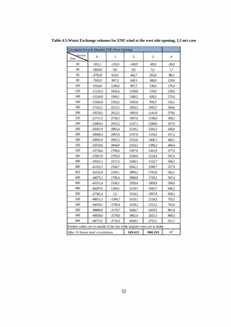
52
Table 4.5:Water Exchange volumes for ENE wind at the west side opening, 1,5 m/s case
Circulation Present Situation-ESE-West Opening
Time Section
0 1 2 3 4
20 -951,1 -210,5 -149,9 -89,9 -30,0
40 -2820,0 9,6 8,5 5,1 1,7
60 -4792,8 614,5 442,7 265,6 88,5
80 -7026,5 897,3 648,1 388,9 129,6
100 -9164,0 1240,0 897,7 538,6 179,4
120 -11135,3 1656,6 1199,8 719,9 239,6
140 -13334,9 1904,1 1380,5 828,3 275,6
160 -15420,9 2183,2 1583,8 950,3 316,1
180 -17352,1 2515,2 1826,2 1095,7 364,6
200 -19558,5 2612,5 1903,0 1141,8 379,6
220 -21717,5 2730,3 1997,4 1198,9 398,1
240 -23804,3 2915,2 2147,1 1288,8 427,9
260 -26267,0 2865,4 2139,2 1283,5 426,0
280 -28688,3 2887,8 2197,0 1318,2 437,2
300 -30991,9 2991,5 2332,6 1400,1 464,1
320 -33519,6 2844,9 2314,3 1390,2 460,4
340 -35726,6 2798,4 2397,6 1441,9 477,0
360 -37607,0 2795,8 2548,0 1534,4 507,4
380 -39561,5 2517,3 2540,3 1532,7 506,5
400 -41163,7 2338,7 2641,1 1598,7 527,9
420 -42533,4 2190,1 2800,2 1702,8 562,1
440 -44075,1 1798,4 2808,8 1720,3 567,4
460 -45311,4 1536,2 2929,4 1809,9 596,6
480 -46297,6 1394,5 3110,7 1941,7 640,1
500 -47381,4 5,5 3154,2 1997,8 658,1
520 -48051,5 -1384,7 3319,1 2134,5 703,2
540 -48430,1 -1700,4 3539,2 2312,2 762,4
560 -48880,0 -2174,7 3646,7 2429,5 801,8
580 -48928,0 -2578,6 3862,4 2621,5 866,5
600 -48772,5 -2710,3 4028,5 2755,7 911,7
Positive values are to outside of the bay while negative ones are to inside
After 10 hours total circulations 169.611 -900.293 m3
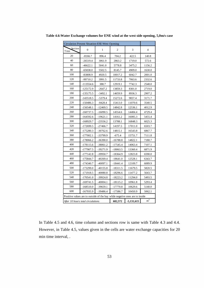
53
Table 4.6:Water Exchange volumes for ENE wind at the west side opening, 5,0m/s case
In Table 4.5 and 4.6, time column and sections row is same with Table 4.3 and 4.4.
However, in Table 4.5, values given in the cells are water exchange capacities for 20
min time interval, .
Circulation Present Situation-ESE-West Opening
Time Section
0 1 2 3 4
20 -8166.7 896.4 704.2 422.5 140.8
40 -26519.4 3061.9 2863.2 1719.0 572.6
60 -46622.1 5041.0 5778.8 3475.2 1156.2
80 -65838.0 5502.5 8145.7 4909.0 1630.0
100 -83808.9 4920.5 10017.2 6042.7 2001.0
120 -99710.2 3991.5 11733.8 7063.6 2332.6
140 -113554.6 388.7 12919.1 7742.3 2548.0
160 -125172.9 -2647.2 13859.3 8301.0 2719.0
180 -135175.5 -3492.1 14659.9 8936.3 2907.2
200 -143518.5 -5379.4 15272.6 9837.4 3171.7
220 -150486.3 -8428.4 15413.0 11070.6 3540.5
240 -156548.1 -12469.5 14842.8 12536.1 4012.9
260 -160737.5 -16090.5 14554.6 14484.4 4729.4
280 -164592.6 -19621.1 14161.2 16085.3 5455.4
300 -168929.7 -23556.2 13788.1 16848.3 6025.3
320 -172699.5 -27466.7 14197.5 17011.0 6503.7
340 -175280.3 -30762.6 14815.1 16543.8 6867.7
360 -177002.1 -33799.9 -675.4 15751.7 7111.8
380 -178066.2 -36390.0 -16788.8 14822.1 7180.7
400 -178115.6 -38061.2 -17545.4 14063.4 7107.1
420 -177907.5 -39271.9 -18063.5 13360.4 6871.9
440 -177142.8 -39950.7 -18364.9 12823.8 6590.0
460 -175844.7 -40269.4 -18641.0 12528.1 6343.7
480 -174340.7 -40097.1 -18441.4 12109.7 6089.9
500 -173299.0 -40155.8 -18311.5 11679.5 5820.5
520 -171918.5 -40080.8 -18296.6 11477.2 5643.7
540 -170541.0 -39924.8 -18223.2 11294.0 5493.5
560 -169741.5 -40004.1 -18115.2 10961.8 5293.4
580 -168510.0 -39659.1 -17770.8 10629.6 5140.0
600 -167935.9 -39486.4 -17586.7 10450.9 5062.1
Positive values are to outside of the bay while negative ones are to inside
After 10 hours total circulations 682,572 -5,131,615 m3
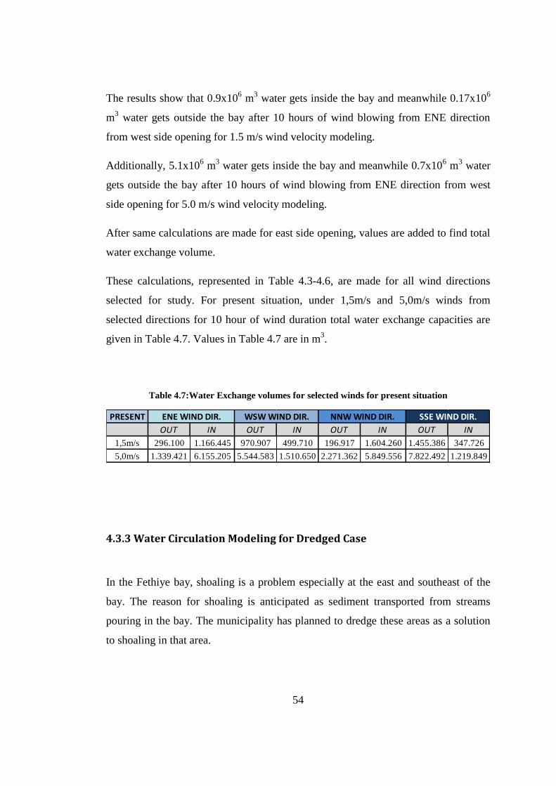
54
The results show that 0.9x10⁶ m
3 water gets inside the bay and meanwhile 0.17x10
6
m3 water gets outside the bay after 10 hours of wind blowing from ENE direction
from west side opening for 1.5 m/s wind velocity modeling.
Additionally, 5.1x10⁶ m
3 water gets inside the bay and meanwhile 0.7x10
6 m
3 water
gets outside the bay after 10 hours of wind blowing from ENE direction from west
side opening for 5.0 m/s wind velocity modeling.
After same calculations are made for east side opening, values are added to find total
water exchange volume.
These calculations, represented in Table 4.3-4.6, are made for all wind directions
selected for study. For present situation, under 1,5m/s and 5,0m/s winds from
selected directions for 10 hour of wind duration total water exchange capacities are
given in Table 4.7. Values in Table 4.7 are in m3.
Table 4.7:Water Exchange volumes for selected winds for present situation
4.3.3 Water Circulation Modeling for Dredged Case
In the Fethiye bay, shoaling is a problem especially at the east and southeast of the
bay. The reason for shoaling is anticipated as sediment transported from streams
pouring in the bay. The municipality has planned to dredge these areas as a solution
to shoaling in that area.
PRESENT
OUT IN OUT IN OUT IN OUT IN
1,5m/s 296.100 1.166.445 970.907 499.710 196.917 1.604.260 1.455.386 347.726
5,0m/s 1.339.421 6.155.205 5.544.583 1.510.650 2.271.362 5.849.556 7.822.492 1.219.849
ENE WIND DIR. WSW WIND DIR. NNW WIND DIR. SSE WIND DIR.
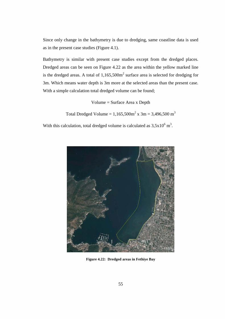
55
Since only change in the bathymetry is due to dredging, same coastline data is used
as in the present case studies (Figure 4.1).
Bathymetry is similar with present case studies except from the dredged places.
Dredged areas can be seen on Figure 4.22 as the area within the yellow marked line
is the dredged areas. A total of 1,165,500m2 surface area is selected for dredging for
3m. Which means water depth is 3m more at the selected areas than the present case.
With a simple calculation total dredged volume can be found;
Volume = Surface Area x Depth
Total Dredged Volume = 1,165,500m2 x 3m = 3,496,500 m
3
With this calculation, total dredged volume is calculated as 3,5x10⁶ m
3.
Figure 4.22: Dredged areas in Fethiye Bay
56
In order to calculate water exchange in the inner bay for dredged case conditions,
same cross sections are used as in the present situation case from east side opening
and west side opening of the bay (Figure 4.7-4.10).
Time variable water circulation is modeled for Fethiye bay, under different wind
conditions for dredging applied bathymetrical conditions. In order to observe change
in water exchange capacity, same meteorological conditions are applied with the
present situation studies. In other words, four different wind directions are applied on
the model. NNW, SSE, ENE and WSW wind directions are used for modeling.
Firstly, wind blowing from the NNW direction, for two different wind velocities; 1.5
m/s and 5 m/s velocities, for 10 hours is applied. In addition, with the same order,
written modeling results are given for places closer to the bottom of the sea and for
places closer to the water surface in Figure 4.23 – 4.30. In these figures, left side
shows pattern of model results from 1,5m/s wind velocity and right side shows the
ones from the 5,0m/s wind velocity.
If circulation models of present case and dredged case are compared it is observed
that circulation patterns are similar with each other. In both cases for the same wind
directions at the same depths, results are very similar to each other. For NNW and
SSE cases, at the east side of the inner bay, eddies occur. For all the wind cases,
water at places closer to the sea surface and water at places closer to the sea bottom
moves to the opposite directions which results in water circulation.
So far, when present case and dredged cases are compared, dredging of shown areas
does not have an impact to the water circulation patterns. Whether dredging has an
influence on water exchange capacities will be revealed after exchange capacity
calculations.
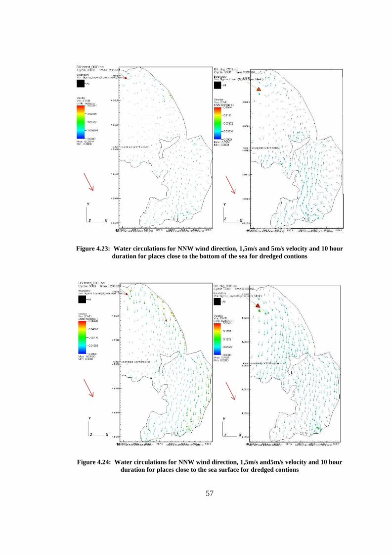
57
Figure 4.23: Water circulations for NNW wind direction, 1,5m/s and 5m/s velocity and 10 hour
duration for places close to the bottom of the sea for dredged contions
Figure 4.24: Water circulations for NNW wind direction, 1,5m/s and5m/s velocity and 10 hour
duration for places close to the sea surface for dredged contions
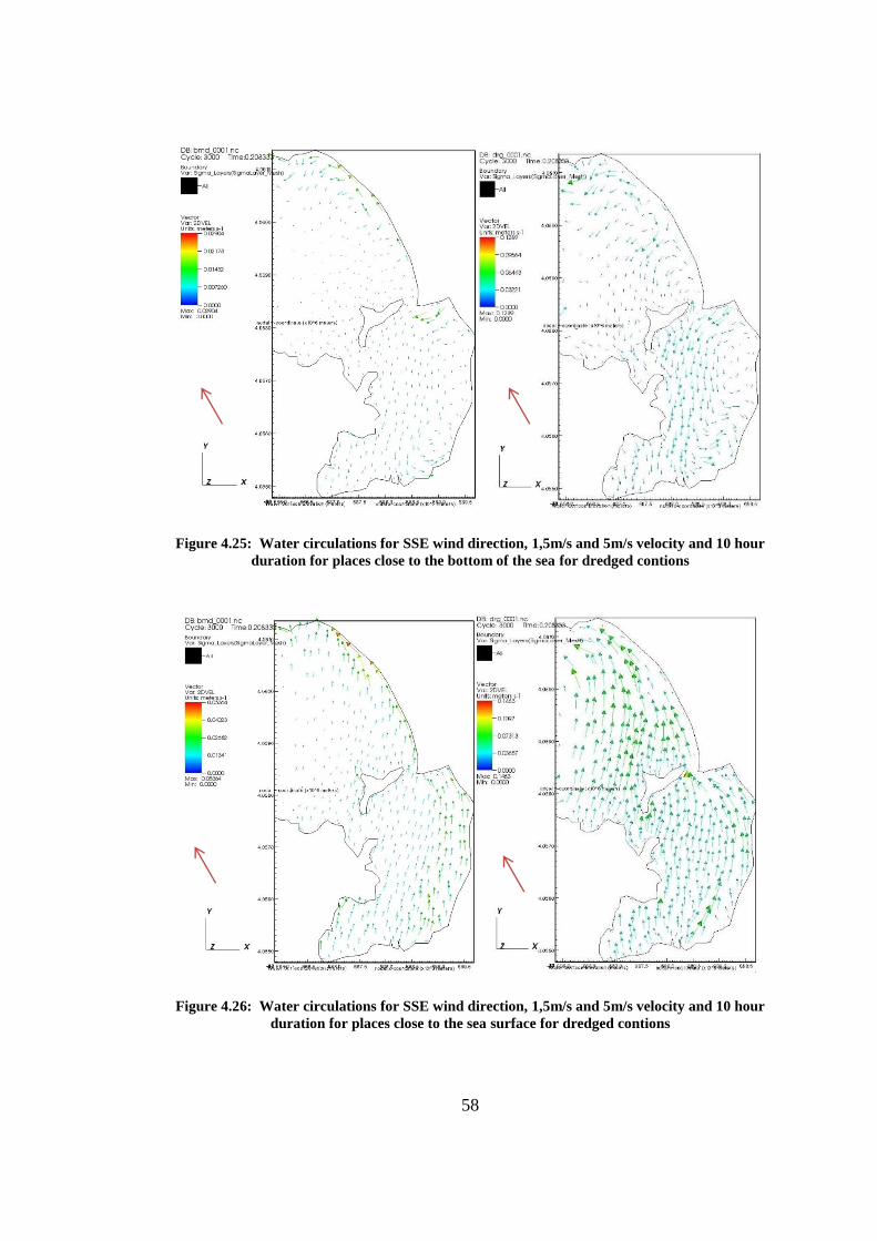
58
Figure 4.25: Water circulations for SSE wind direction, 1,5m/s and 5m/s velocity and 10 hour
duration for places close to the bottom of the sea for dredged contions
Figure 4.26: Water circulations for SSE wind direction, 1,5m/s and 5m/s velocity and 10 hour
duration for places close to the sea surface for dredged contions
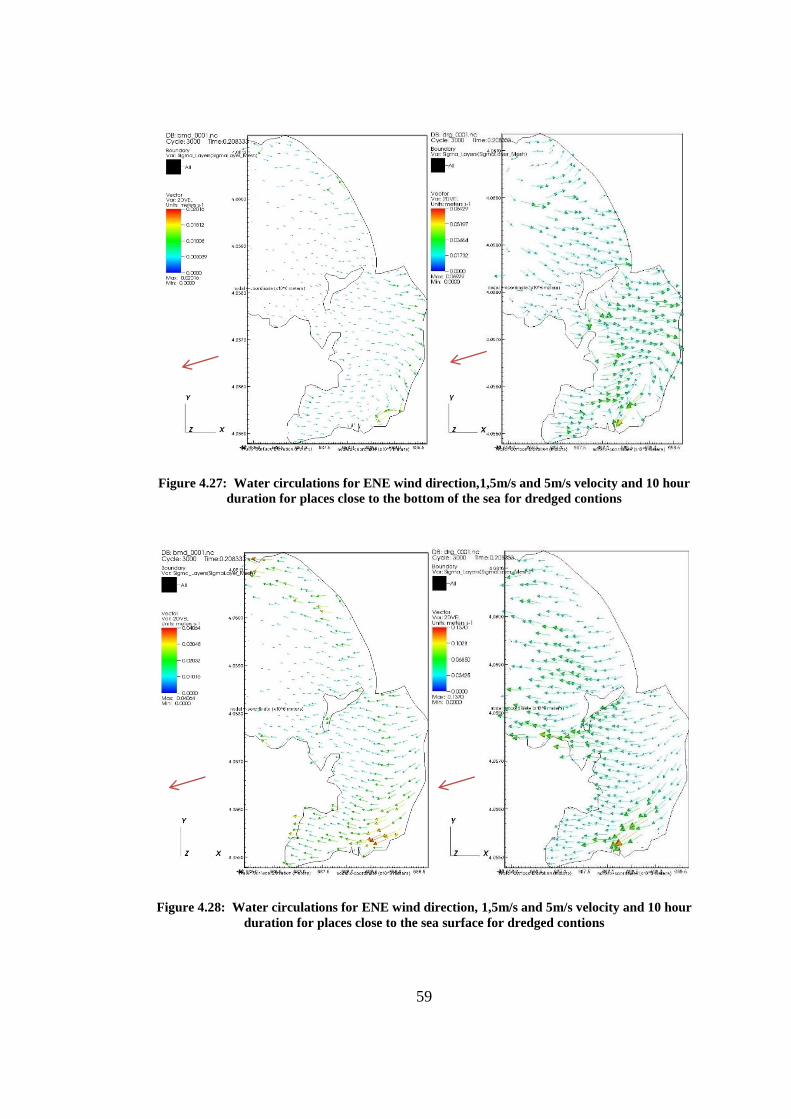
59
Figure 4.27: Water circulations for ENE wind direction,1,5m/s and 5m/s velocity and 10 hour
duration for places close to the bottom of the sea for dredged contions
Figure 4.28: Water circulations for ENE wind direction, 1,5m/s and 5m/s velocity and 10 hour
duration for places close to the sea surface for dredged contions
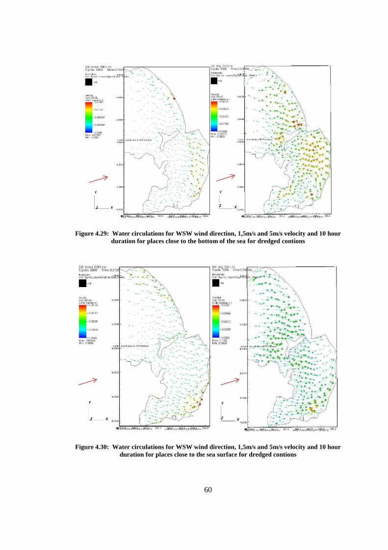
60
Figure 4.29: Water circulations for WSW wind direction, 1,5m/s and 5m/s velocity and 10 hour
duration for places close to the bottom of the sea for dredged contions
Figure 4.30: Water circulations for WSW wind direction, 1,5m/s and 5m/s velocity and 10 hour
duration for places close to the sea surface for dredged contions
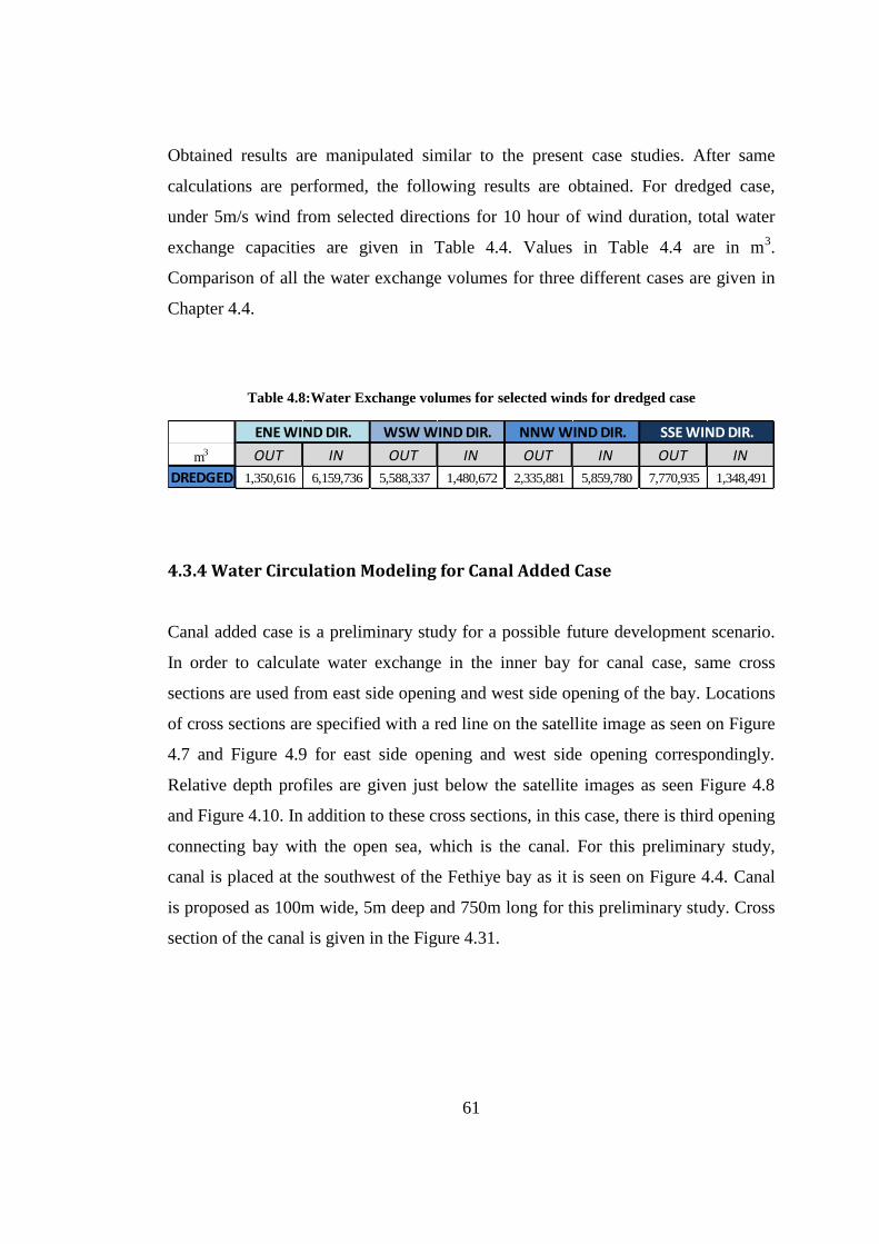
61
Obtained results are manipulated similar to the present case studies. After same
calculations are performed, the following results are obtained. For dredged case,
under 5m/s wind from selected directions for 10 hour of wind duration, total water
exchange capacities are given in Table 4.4. Values in Table 4.4 are in m3.
Comparison of all the water exchange volumes for three different cases are given in
Chapter 4.4.
Table 4.8:Water Exchange volumes for selected winds for dredged case
4.3.4 Water Circulation Modeling for Canal Added Case
Canal added case is a preliminary study for a possible future development scenario.
In order to calculate water exchange in the inner bay for canal case, same cross
sections are used from east side opening and west side opening of the bay. Locations
of cross sections are specified with a red line on the satellite image as seen on Figure
4.7 and Figure 4.9 for east side opening and west side opening correspondingly.
Relative depth profiles are given just below the satellite images as seen Figure 4.8
and Figure 4.10. In addition to these cross sections, in this case, there is third opening
connecting bay with the open sea, which is the canal. For this preliminary study,
canal is placed at the southwest of the Fethiye bay as it is seen on Figure 4.4. Canal
is proposed as 100m wide, 5m deep and 750m long for this preliminary study. Cross
section of the canal is given in the Figure 4.31.
m3 OUT IN OUT IN OUT IN OUT IN
DREDGED 1,350,616 6,159,736 5,588,337 1,480,672 2,335,881 5,859,780 7,770,935 1,348,491
ENE WIND DIR. WSW WIND DIR. NNW WIND DIR. SSE WIND DIR.
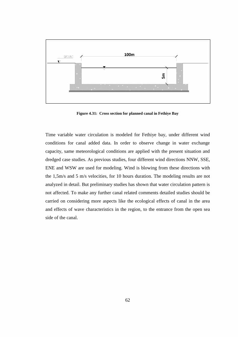
62
Figure 4.31: Cross section for planned canal in Fethiye Bay
Time variable water circulation is modeled for Fethiye bay, under different wind
conditions for canal added data. In order to observe change in water exchange
capacity, same meteorological conditions are applied with the present situation and
dredged case studies. As previous studies, four different wind directions NNW, SSE,
ENE and WSW are used for modeling. Wind is blowing from these directions with
the 1,5m/s and 5 m/s velocities, for 10 hours duration. The modeling results are not
analyzed in detail. But preliminary studies has shown that water circulation pattern is
not affected. To make any further canal related comments detailed studies should be
carried on considering more aspects like the ecological effects of canal in the area
and effects of wave characteristics in the region, to the entrance from the open sea
side of the canal.
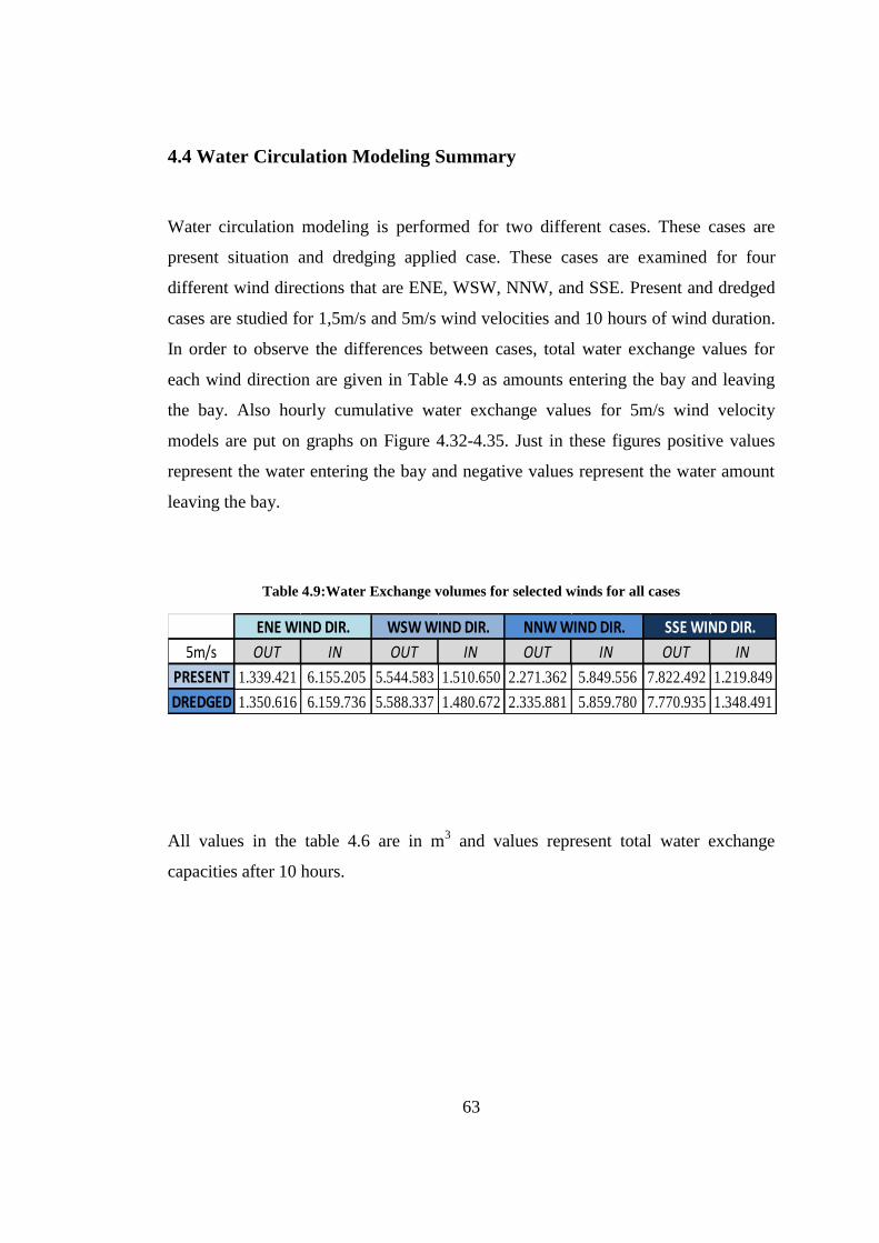
63
4.4 Water Circulation Modeling Summary
Water circulation modeling is performed for two different cases. These cases are
present situation and dredging applied case. These cases are examined for four
different wind directions that are ENE, WSW, NNW, and SSE. Present and dredged
cases are studied for 1,5m/s and 5m/s wind velocities and 10 hours of wind duration.
In order to observe the differences between cases, total water exchange values for
each wind direction are given in Table 4.9 as amounts entering the bay and leaving
the bay. Also hourly cumulative water exchange values for 5m/s wind velocity
models are put on graphs on Figure 4.32-4.35. Just in these figures positive values
represent the water entering the bay and negative values represent the water amount
leaving the bay.
Table 4.9:Water Exchange volumes for selected winds for all cases
All values in the table 4.6 are in m3 and values represent total water exchange
capacities after 10 hours.
5m/s OUT IN OUT IN OUT IN OUT IN
PRESENT 1.339.421 6.155.205 5.544.583 1.510.650 2.271.362 5.849.556 7.822.492 1.219.849
DREDGED 1.350.616 6.159.736 5.588.337 1.480.672 2.335.881 5.859.780 7.770.935 1.348.491
ENE WIND DIR. WSW WIND DIR. NNW WIND DIR. SSE WIND DIR.
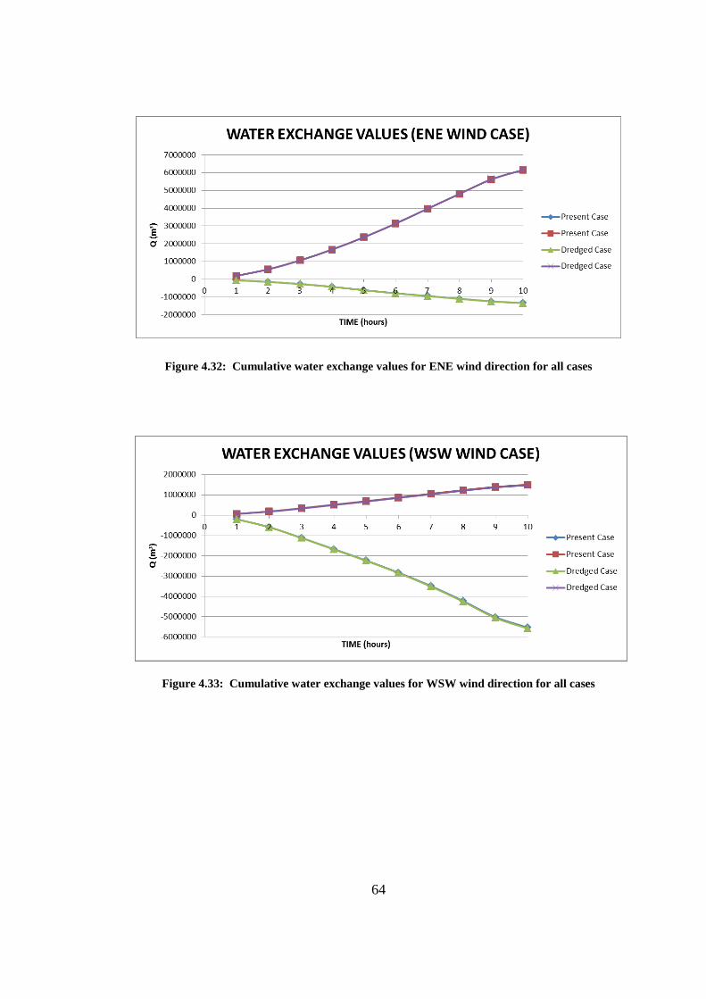
64
Figure 4.32: Cumulative water exchange values for ENE wind direction for all cases
Figure 4.33: Cumulative water exchange values for WSW wind direction for all cases
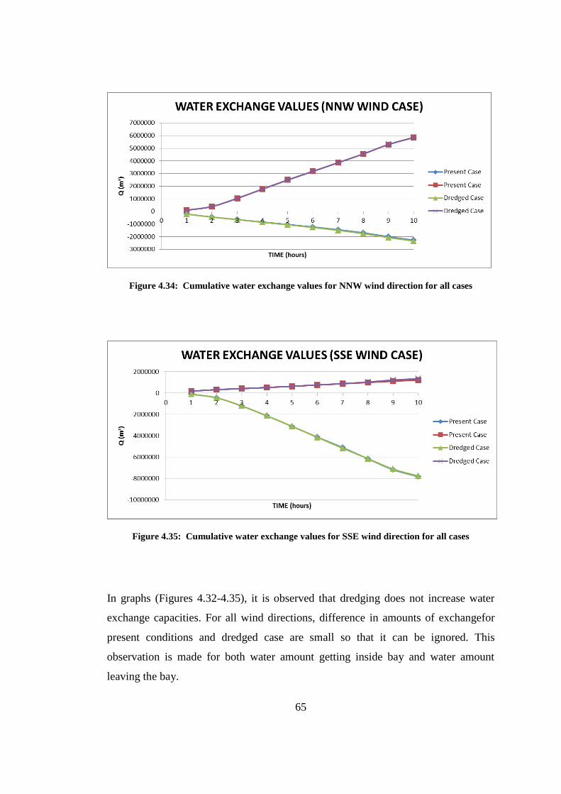
65
Figure 4.34: Cumulative water exchange values for NNW wind direction for all cases
Figure 4.35: Cumulative water exchange values for SSE wind direction for all cases
In graphs (Figures 4.32-4.35), it is observed that dredging does not increase water
exchange capacities. For all wind directions, difference in amounts of exchangefor
present conditions and dredged case are small so that it can be ignored. This
observation is made for both water amount getting inside bay and water amount
leaving the bay.
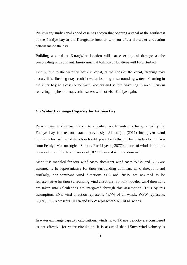
66
Preliminary study canal added case has shown that opening a canal at the southwest
of the Fethiye bay at the Karagözler location will not affect the water circulation
pattern inside the bay.
Building a canal at Karagözler location will cause ecological damage at the
surrounding environment. Environmental balance of locations will be disturbed.
Finally, due to the water velocity in canal, at the ends of the canal, flushing may
occur. This, flushing may result in water foaming in surrounding waters. Foaming in
the inner bay will disturb the yacht owners and sailors travelling in area. Thus in
repeating on phenomena, yacht owners will not visit Fethiye again.
4.5 Water Exchange Capacity for Fethiye Bay
Present case studies are chosen to calculate yearly water exchange capacity for
Fethiye bay for reasons stated previously. Akbaşoğlu (2011) has given wind
durations for each wind direction for 41 years for Fethiye. This data has been taken
from Fethiye Meteorological Station. For 41 years, 357704 hours of wind duration is
observed from this data. Then yearly 8724 hours of wind is observed.
Since it is modeled for four wind cases, dominant wind cases WSW and ENE are
assumed to be representative for their surrounding dominant wind directions and
similarly, non-dominant wind directions SSE and NNW are assumed to be
representative for their surrounding wind directions. So non-modeled wind directions
are taken into calculations are integrated through this assumption. Thus by this
assumption, ENE wind direction represents 43,7% of all winds, WSW represents
36,6%, SSE represents 10.1% and NNW represents 9.6% of all winds.
In water exchange capacity calculations, winds up to 1.0 m/s velocity are considered
as not effective for water circulation. It is assumed that 1.5m/s wind velocity is

67
representative for wind with low velocities and long yearly durations. On the other
hand, 5m/s is assumed as representative for high velocity and short durations of
yearly wind data. Water exchange values of 1,5m/s and 5m/s for 10 hours durations
and for the present case conditions are given in Table 4.7.
For all wind directions, considering the percentages and durations, yearly water
exchange capacity of Fethiye bay is 1672x106 m
3. Since wind cases are modeled
fresh water entrance is considered, separate calculations for freshwater does not have
to be added to this value.
68
CHAPTER 5
YACHT CARRYING CAPACITY
5.1 Sustainable Development
Economic development for increasing life quality is a necessity in the modern
communities. However, when the level of development extends beyond the limits of
the nature, development will be short-termed. The natural resources will be over-
exploited in an irreversible manner and finally this will result in environmental
destruction and economic failure. Sustainable development is a way to provide the
needs of people within the environmental limits. While proposals are put forward for
economic growth, this should cause minimal or no damage to environmental
systems. Main purpose of sustainable development is to provide our needs while
making sure that we left the future generations economic and environmental
conditions so that they are able to provide their needs.
5.1.1 Integrated Coastal Zone Management
Currently, 75% of the world population is living in the coastal areas and immigration
to coastal areas is going on constantly. Demand is not expected to stop on coastal
areas any time soon. That puts a great environmental pressure on coastal zones.
Pressure on the developed, industrially improved coasts is a bigger problem since
part of industrial improvement is building structures in coastal zones like power
plants, ports, marinas that might cause disruption in environmental systems.
Moreover, tourism activities put an extra stress on existing conditions. Air and sea
pollution in coastal areas is mainly caused by these activities.
69
Integrated coastal zone management intends all participants to work in harmony for
coastal improvement under the sustainable development conditions namely balancing
exploitation and conservation. Participants are policy makers, investors, industry
presenters, planners and managers of coastal zones and local citizens. In integrated
coastal zone management, involvement of multiple-sectors is an obligation for
sustainable development. For benefit of all participants, goals should be set properly
to reverse negative incidents.
5.2 Carrying Capacity Assessment
In many coastal zones, people living in that area are dependent on tourism income.
Since tourism is such an important sector for coastal areas and it is highly dependent
on ecology, tourism and ecology cannot be treated separately. If an increasing
tourism income is desired, ecology should also be preserved. Because, nobody
especially a tourist wants to face air and seawater pollution during his/her visit.
Yacht tourism, especially, makes up a big percentage of tourism income of a country
within coastal areas. Since yachting is an expensive pursuit and correspondingly
yachtsmen are rich people who spends a lot money. Yachting is usually made with
midsize boats on a random route that yachtsmen decide. In addition, yachting can be
defined as joyful, restful, entertaining sporting experience. Yachtsmen are always
looking for new places to visit. Spain, France and Italy are most popular places in
Europe among the yachtsmen. However, these countries almost reached or has
already reached their carrying capacities and yachtsmen are looking for new places
to explore. Turkey Riviera offers the clearest waters in the eastern Mediterranean and
invests in the yacht tourism. However, with excessive usage, yachting can cause
environmental damage as previously mentioned.
Seawater pollution level depends on liquid wastes disposed from yachts, solid wastes
threw randomly instead of solid waste collecting equipment. On the other hand,
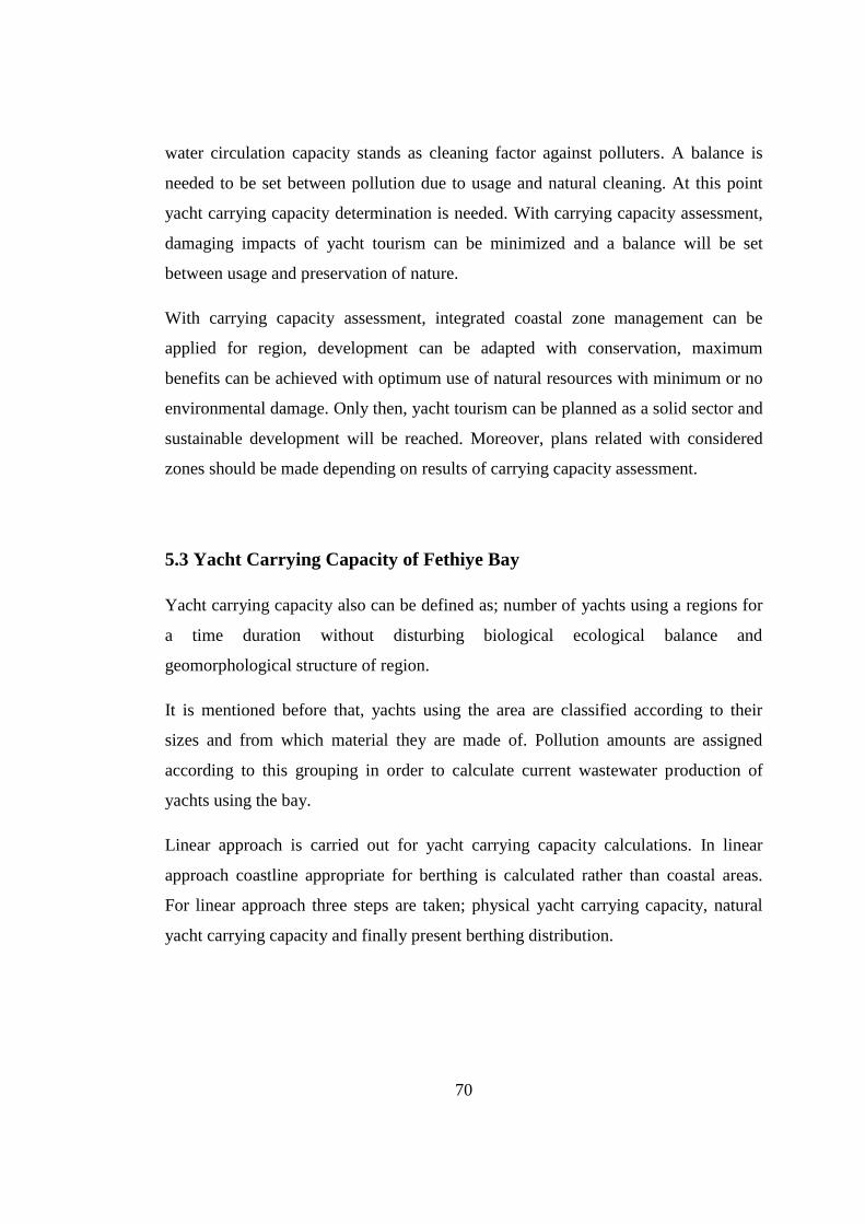
70
water circulation capacity stands as cleaning factor against polluters. A balance is
needed to be set between pollution due to usage and natural cleaning. At this point
yacht carrying capacity determination is needed. With carrying capacity assessment,
damaging impacts of yacht tourism can be minimized and a balance will be set
between usage and preservation of nature.
With carrying capacity assessment, integrated coastal zone management can be
applied for region, development can be adapted with conservation, maximum
benefits can be achieved with optimum use of natural resources with minimum or no
environmental damage. Only then, yacht tourism can be planned as a solid sector and
sustainable development will be reached. Moreover, plans related with considered
zones should be made depending on results of carrying capacity assessment.
5.3 Yacht Carrying Capacity of Fethiye Bay
Yacht carrying capacity also can be defined as; number of yachts using a regions for
a time duration without disturbing biological ecological balance and
geomorphological structure of region.
It is mentioned before that, yachts using the area are classified according to their
sizes and from which material they are made of. Pollution amounts are assigned
according to this grouping in order to calculate current wastewater production of
yachts using the bay.
Linear approach is carried out for yacht carrying capacity calculations. In linear
approach coastline appropriate for berthing is calculated rather than coastal areas.
For linear approach three steps are taken; physical yacht carrying capacity, natural
yacht carrying capacity and finally present berthing distribution.
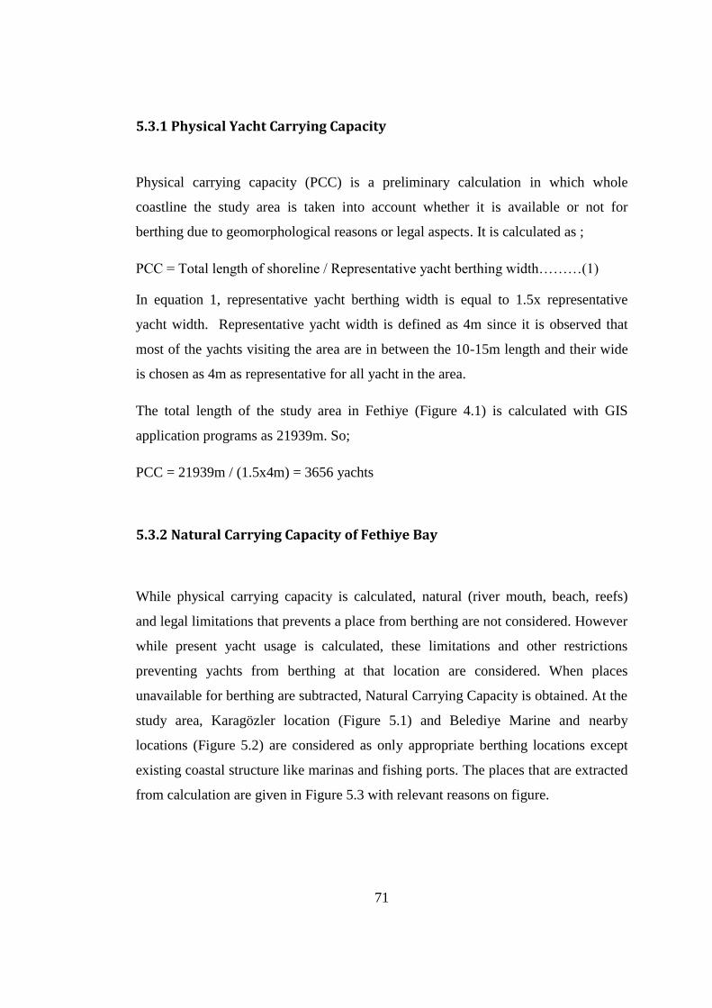
71
5.3.1 Physical Yacht Carrying Capacity
Physical carrying capacity (PCC) is a preliminary calculation in which whole
coastline the study area is taken into account whether it is available or not for
berthing due to geomorphological reasons or legal aspects. It is calculated as ;
PCC = Total length of shoreline / Representative yacht berthing width………(1)
In equation 1, representative yacht berthing width is equal to 1.5x representative
yacht width. Representative yacht width is defined as 4m since it is observed that
most of the yachts visiting the area are in between the 10-15m length and their wide
is chosen as 4m as representative for all yacht in the area.
The total length of the study area in Fethiye (Figure 4.1) is calculated with GIS
application programs as 21939m. So;
PCC = 21939m / (1.5x4m) = 3656 yachts
5.3.2 Natural Carrying Capacity of Fethiye Bay
While physical carrying capacity is calculated, natural (river mouth, beach, reefs)
and legal limitations that prevents a place from berthing are not considered. However
while present yacht usage is calculated, these limitations and other restrictions
preventing yachts from berthing at that location are considered. When places
unavailable for berthing are subtracted, Natural Carrying Capacity is obtained. At the
study area, Karagözler location (Figure 5.1) and Belediye Marine and nearby
locations (Figure 5.2) are considered as only appropriate berthing locations except
existing coastal structure like marinas and fishing ports. The places that are extracted
from calculation are given in Figure 5.3 with relevant reasons on figure.
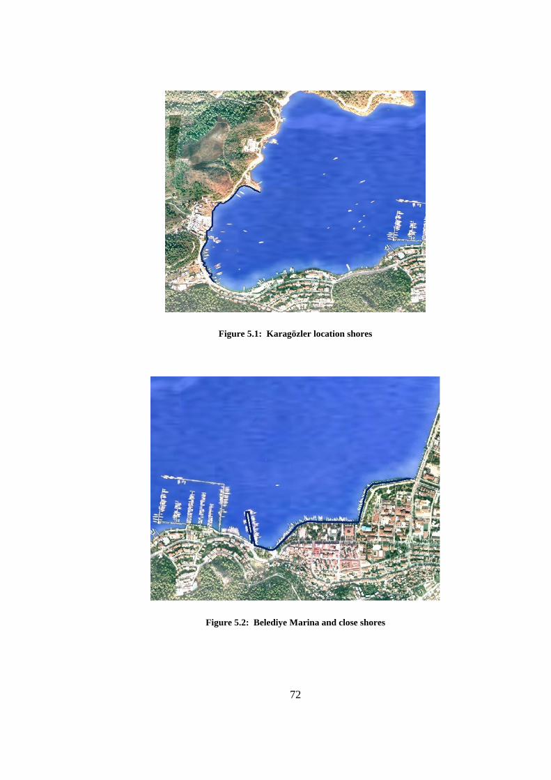
72
Figure 5.1: Karagözler location shores
Figure 5.2: Belediye Marina and close shores
73
Figure 5.3: Extracted locations with reasons
Places marked with blue line at Figure 5.1 and Figure 5.2 is places that are available
for berthing.
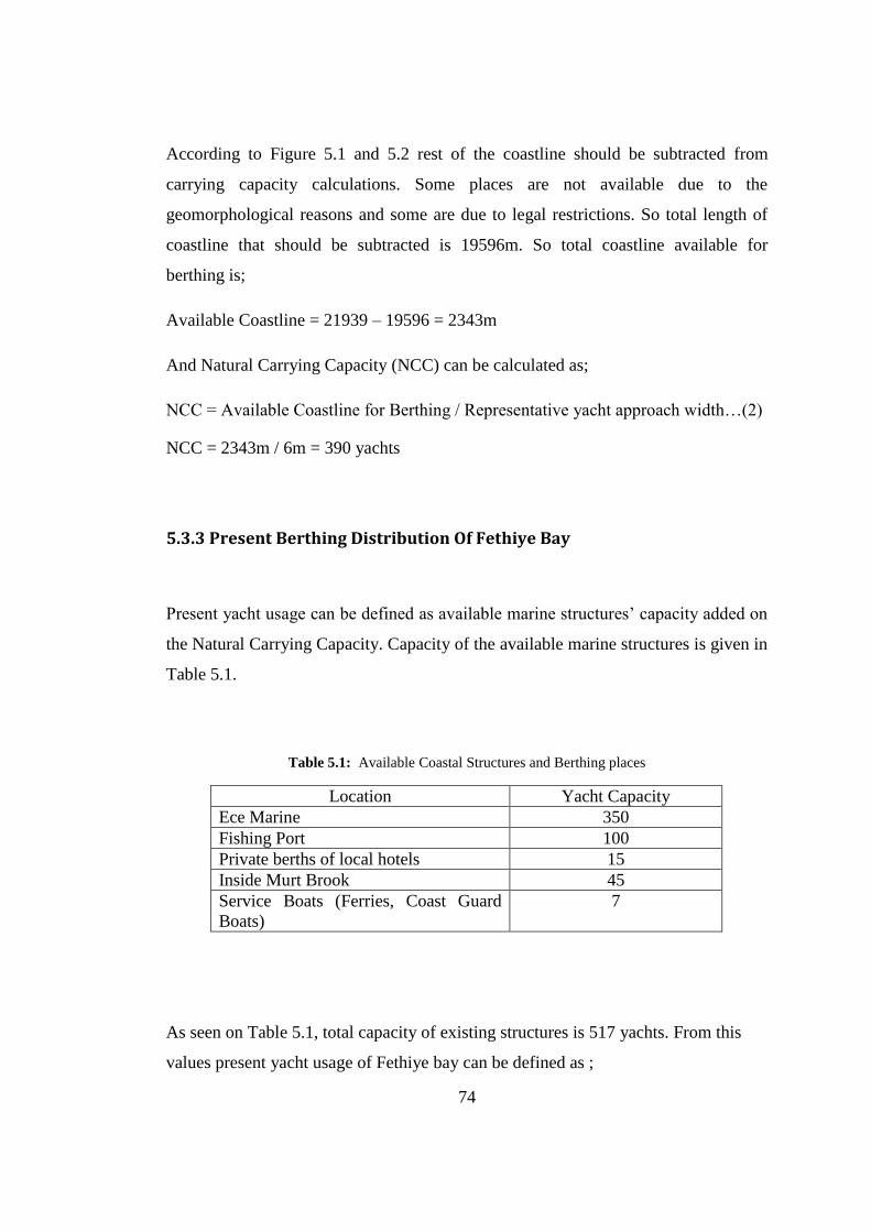
74
According to Figure 5.1 and 5.2 rest of the coastline should be subtracted from
carrying capacity calculations. Some places are not available due to the
geomorphological reasons and some are due to legal restrictions. So total length of
coastline that should be subtracted is 19596m. So total coastline available for
berthing is;
Available Coastline = 21939 – 19596 = 2343m
And Natural Carrying Capacity (NCC) can be calculated as;
NCC = Available Coastline for Berthing / Representative yacht approach width…(2)
NCC = 2343m / 6m = 390 yachts
5.3.3 Present Berthing Distribution Of Fethiye Bay
Present yacht usage can be defined as available marine structures’ capacity added on
the Natural Carrying Capacity. Capacity of the available marine structures is given in
Table 5.1.
Table 5.1: Available Coastal Structures and Berthing places
Location Yacht Capacity
Ece Marine 350
Fishing Port 100
Private berths of local hotels 15
Inside Murt Brook 45
Service Boats (Ferries, Coast Guard
Boats)
7
As seen on Table 5.1, total capacity of existing structures is 517 yachts. From this
values present yacht usage of Fethiye bay can be defined as ;
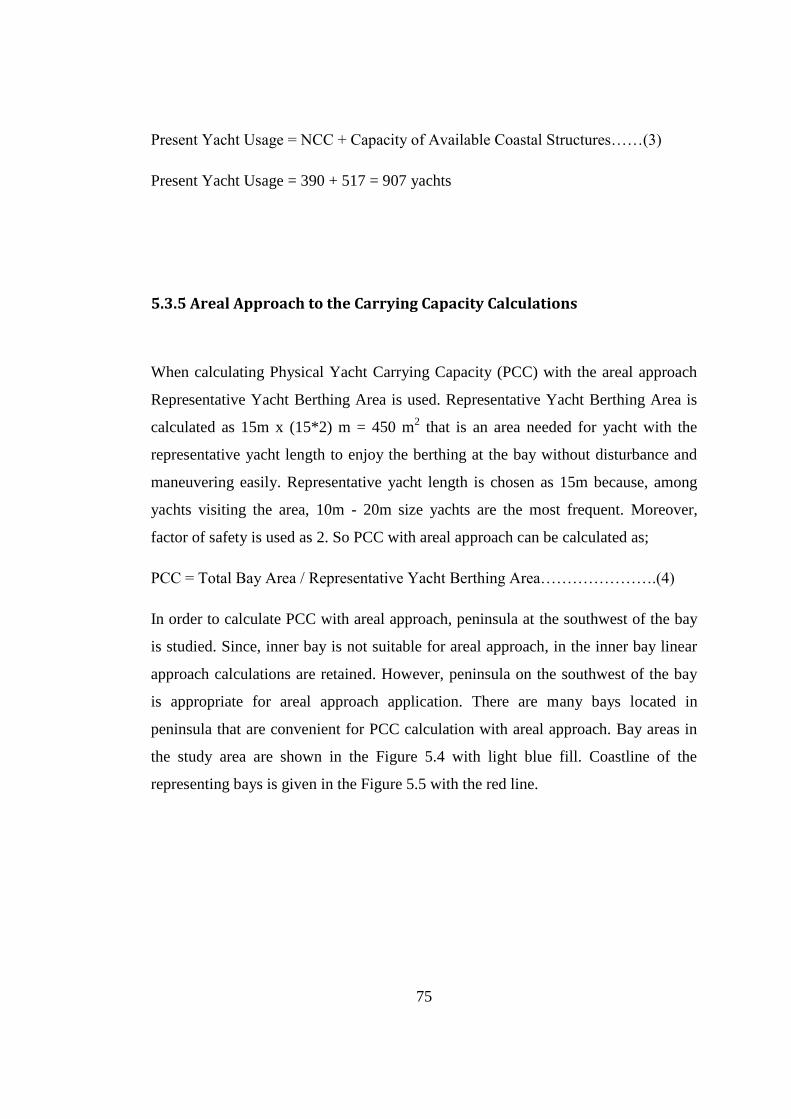
75
Present Yacht Usage = NCC + Capacity of Available Coastal Structures……(3)
Present Yacht Usage = 390 + 517 = 907 yachts
5.3.5 Areal Approach to the Carrying Capacity Calculations
When calculating Physical Yacht Carrying Capacity (PCC) with the areal approach
Representative Yacht Berthing Area is used. Representative Yacht Berthing Area is
calculated as 15m x (15*2) m = 450 m2 that is an area needed for yacht with the
representative yacht length to enjoy the berthing at the bay without disturbance and
maneuvering easily. Representative yacht length is chosen as 15m because, among
yachts visiting the area, 10m - 20m size yachts are the most frequent. Moreover,
factor of safety is used as 2. So PCC with areal approach can be calculated as;
PCC = Total Bay Area / Representative Yacht Berthing Area………………….(4)
In order to calculate PCC with areal approach, peninsula at the southwest of the bay
is studied. Since, inner bay is not suitable for areal approach, in the inner bay linear
approach calculations are retained. However, peninsula on the southwest of the bay
is appropriate for areal approach application. There are many bays located in
peninsula that are convenient for PCC calculation with areal approach. Bay areas in
the study area are shown in the Figure 5.4 with light blue fill. Coastline of the
representing bays is given in the Figure 5.5 with the red line.
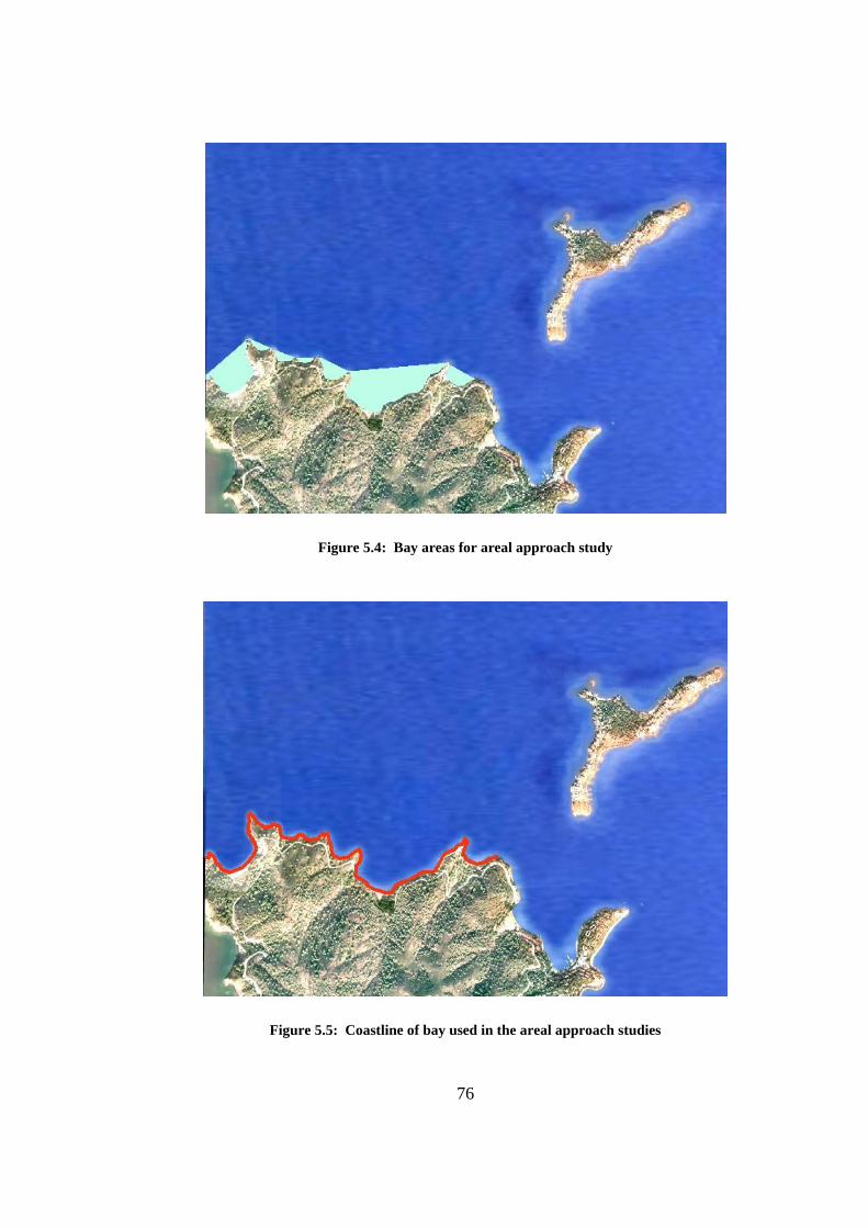
76
Figure 5.4: Bay areas for areal approach study
Figure 5.5: Coastline of bay used in the areal approach studies
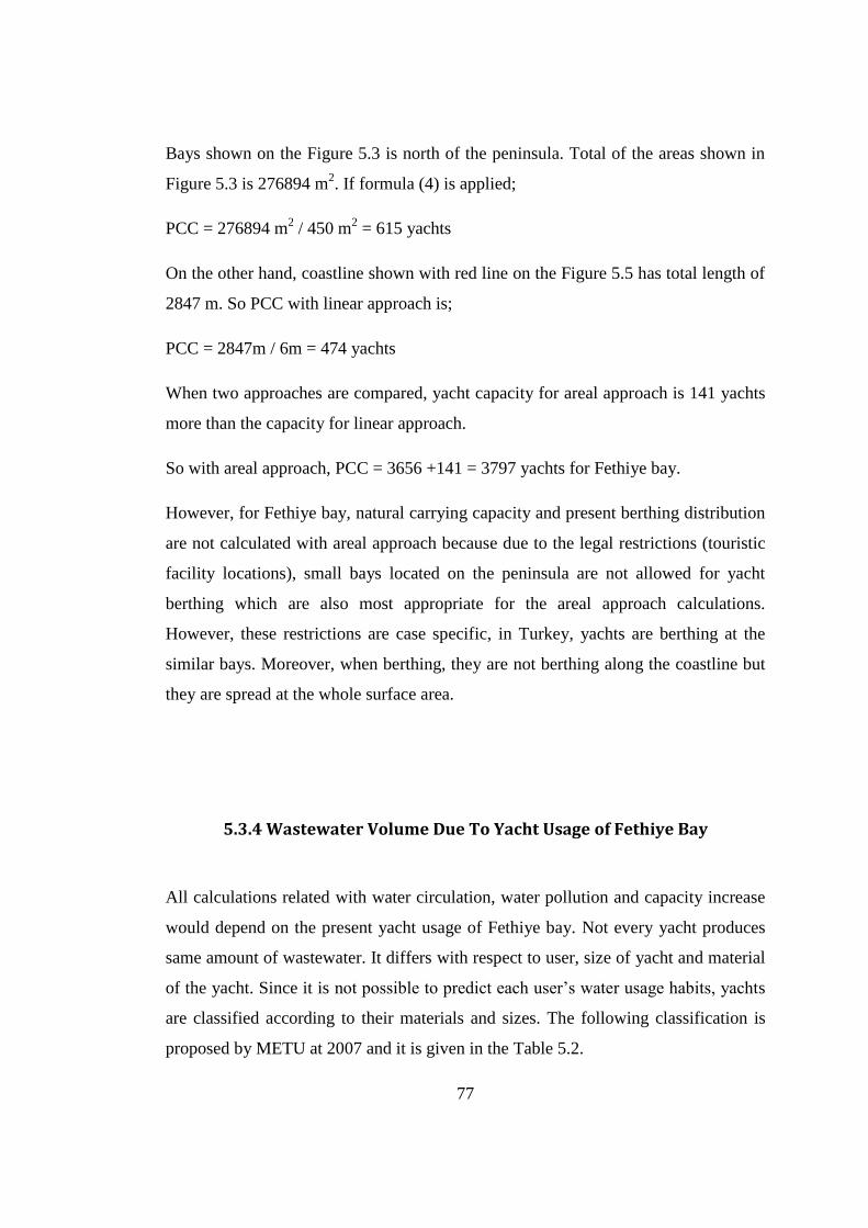
77
Bays shown on the Figure 5.3 is north of the peninsula. Total of the areas shown in
Figure 5.3 is 276894 m2. If formula (4) is applied;
PCC = 276894 m2 / 450 m
2 = 615 yachts
On the other hand, coastline shown with red line on the Figure 5.5 has total length of
2847 m. So PCC with linear approach is;
PCC = 2847m / 6m = 474 yachts
When two approaches are compared, yacht capacity for areal approach is 141 yachts
more than the capacity for linear approach.
So with areal approach, PCC = 3656 +141 = 3797 yachts for Fethiye bay.
However, for Fethiye bay, natural carrying capacity and present berthing distribution
are not calculated with areal approach because due to the legal restrictions (touristic
facility locations), small bays located on the peninsula are not allowed for yacht
berthing which are also most appropriate for the areal approach calculations.
However, these restrictions are case specific, in Turkey, yachts are berthing at the
similar bays. Moreover, when berthing, they are not berthing along the coastline but
they are spread at the whole surface area.
5.3.4 Wastewater Volume Due To Yacht Usage of Fethiye Bay
All calculations related with water circulation, water pollution and capacity increase
would depend on the present yacht usage of Fethiye bay. Not every yacht produces
same amount of wastewater. It differs with respect to user, size of yacht and material
of the yacht. Since it is not possible to predict each user’s water usage habits, yachts
are classified according to their materials and sizes. The following classification is
proposed by METU at 2007 and it is given in the Table 5.2.
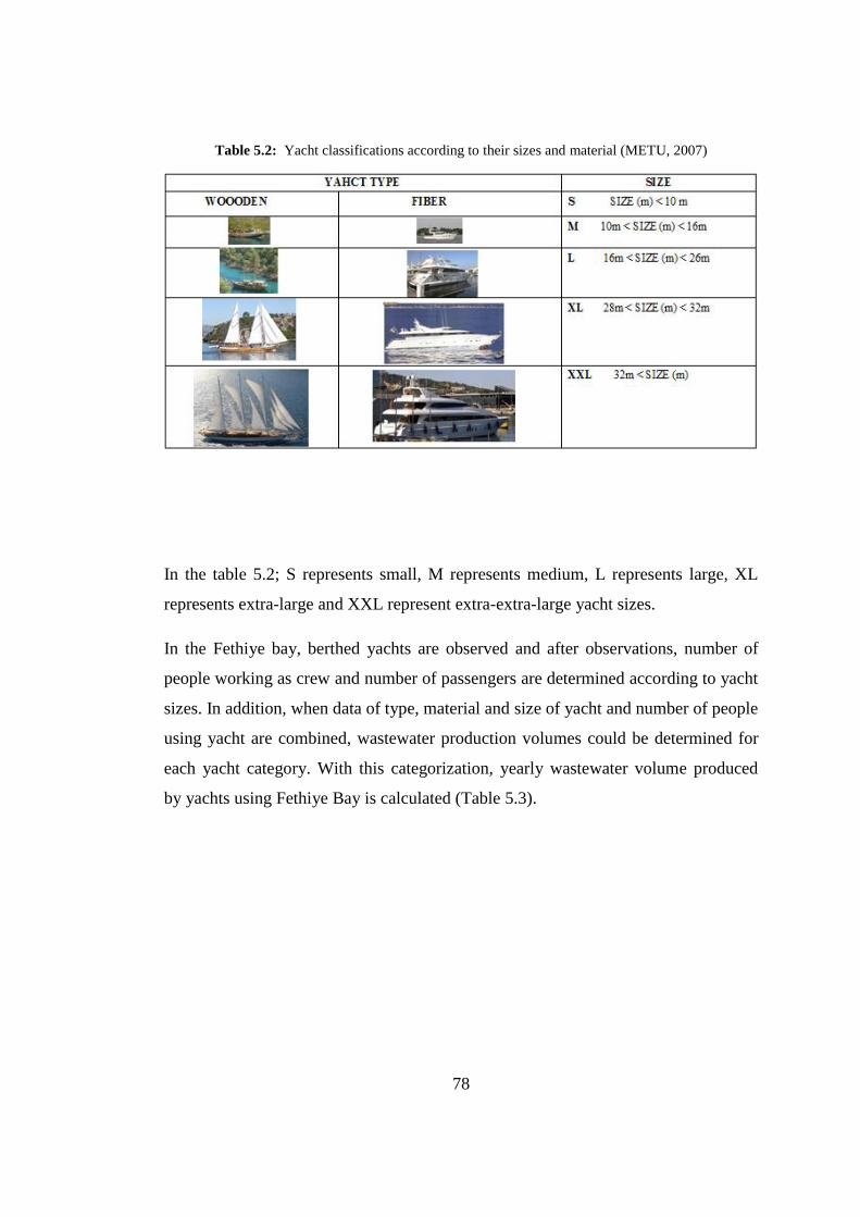
78
Table 5.2: Yacht classifications according to their sizes and material (METU, 2007)
In the table 5.2; S represents small, M represents medium, L represents large, XL
represents extra-large and XXL represent extra-extra-large yacht sizes.
In the Fethiye bay, berthed yachts are observed and after observations, number of
people working as crew and number of passengers are determined according to yacht
sizes. In addition, when data of type, material and size of yacht and number of people
using yacht are combined, wastewater production volumes could be determined for
each yacht category. With this categorization, yearly wastewater volume produced
by yachts using Fethiye Bay is calculated (Table 5.3).
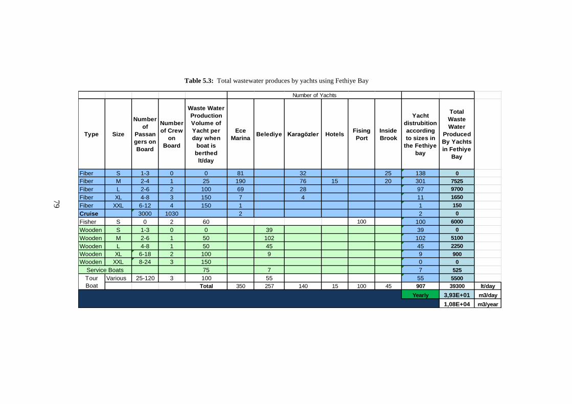
79
Table 5.3: Total wastewater produces by yachts using Fethiye Bay
Type Size
Number
of
Passan
gers on
Board
Number
of Crew
on
Board
Waste Water
Production
Volume of
Yacht per
day when
boat is
berthed
lt/day
Ece
MarinaBelediye Karagözler Hotels
Fising
Port
Inside
Brook
Yacht
distrubition
according
to sizes in
the Fethiye
bay
Total
Waste
Water
Produced
By Yachts
in Fethiye
Bay
Fiber S 1-3 0 0 81 32 25 138 0
Fiber M 2-4 1 25 190 76 15 20 301 7525
Fiber L 2-6 2 100 69 28 97 9700
Fiber XL 4-8 3 150 7 4 11 1650
Fiber XXL 6-12 4 150 1 1 150
Cruise 3000 1030 2 2 0
Fisher S 0 2 60 100 100 6000
Wooden S 1-3 0 0 39 39 0
Wooden M 2-6 1 50 102 102 5100
Wooden L 4-8 1 50 45 45 2250
Wooden XL 6-18 2 100 9 9 900
Wooden XXL 8-24 3 150 0 0
75 7 7 525
Various 25-120 3 100 55 55 5500
Total 350 257 140 15 100 45 907 39300 lt/day
Yearly 3,93E+01 m3/day
1,08E+04 m3/year
Number of Yachts
Tour
Boat
Service Boats
79
80
In Table 5.3, categorization according to size and material of yacht, purpose of usage
(Tour Boats, Service Boats and Fisher), number of passengers using yacht, crew
working on yacht including captain of yachts using Fethiye are shown and number of
yachts are distributed according to their berthing locations. When, yearly wastewater
volume produced is calculated, not the whole year is taken into account but only
three seasons are calculated. Because during winter, there are just a few people using
their yachts so that it can be ignored in wastewater volume calculations.
Additionally, there are no cruises using Fethiye bay at present but there are some
plans to adapt the Fethiye to cruise routes. Still, cruises do not release any
wastewater to the bay with the technology they are using.
As seen on Table 5.3, yearly 1.08x10⁴ m
3 wastewater is assumed to be released to the
bay from 907 yachts.
81
CHAPTER 6
DISCUSSION OF RESULTS AND CONCLUSION
Fethiye is one of the most visited touristic locations in the Turkey. Tourism is the
greatest income of the region. Determination of yacht carrying capacity in Fethiye
bay has vital importance for local and national economy. As a part of succession in
the sustainable development, yacht carrying capacity had to be determined.
In order to calculate the yacht carrying capacity firstly water circulation analysis are
made so that yearly water exchange capacity is reached. For the water circulation
modeling, three different cases are analyzed by utilizing FVCOM. All of the models
are time dependent and wind included circulation models for a semi-enclosed area,
Fethiye bay. Firstly modeling studies are prepared for the present situation. Due to
the conversations with municipality authorities, it is learnt that dredging at the east
and southeast of the bay and canal opening at the Karagözler location are two of their
possible future projects. Moreover, these changes may change the water exchange
capacity. So, secondly, dredging is applied at the east and southeast of the bay. A
total of 3,5 x 10⁶ m
3 dredging of sediment is modeled. Finally, as a preliminary
study, a canal is added to the present bathymetry at the southeast of the bay at the
Karagözler location. Present case and canal added case are examined under four
different wind directions with 1,5m/s and 5m/s wind velocities and for 10 hours of
wind durations. The wind directions used in the modeling are NNW, SSE, ENE and
WSW directions.
Results and comparison of the two cases indicate that dredging does not contribute
significantly to the water exchange capacity of the bay. Also, canal case preliminary
studies has shown that water circulation pattern is not affected due to opening a canal
at the southwest of the bay.
82
When yacht carrying capacity is calculated present situation is considered. Firstly,
volume of wastewater released by yachts currently using bay is determined as
1.08x10⁴ m
3 yearly.
For possible yacht capacity increase, biological studies should be made considering
the dilution rate of the bay. Two important parameter are presented in this thesis for
dilution rate studies which are yearly wastewater release from yachts and yearly
water exchange capacity of Fethiye bay.
If any berthing capacity increase will be made after further biological studies, while
extra capacity being distributed, sustainable development should be considered. The
extra capacity provided will be only applicable if extra berthing capacity is
concentrated at some locations, through high standard, modern equipped marinas. It
is important because marinas provide services that prevent negative impacts of
yachts, like picking up solid wastes. In addition, some marinas are separating the
recyclable solid wastes and delivers to the authorized institutions. Another service
that marinas provide is to draw the wastewater from the yachts and sent to the sewer
systems. This contributes to the dilution rate of the bay.
When locations for new marinas are decided, it is important that sea traffic is not
disturbed due to high concentration at a place in the bay.
A new concept for yacht carrying capacity studies is proposed as areal approach. Due
to the legal restrictions (touristic facilities at the location), this approach was not able
to applied to be the Fethiye bay. But results shown that areal approach gives safer
results than the linear approach. Areal approach for calculating the carrying capacity
is proposed to be used for places where geomorphologic structure is consisting from
dense bay formation.
83
REFERENCES
Akbaşoğlu S., 2011. Wind-induced circulation and sediment transport in semi-
enclosed basins; case study for Fethiye bay , PhD Thesis, METU, Ankara.
METU Press.
Blumberg, A.F., Mellor, G.L., 1987. A description of a three-dimensional coastal
ocean circulation model. In Three-dimensional Coastal Ocean Model, N.S.
Heaps, Ed., Coastal. Estuar. Sci., 4, 1-6.
Blumberg, A. F., A primer for Ecom-si. Technical Report of HydroQual, Inc., 66 pp,
1994.
Chen, C. H. Liu, R. C. Beardsley, 2003a. An unstructured, finite-volume, three-
dimensional,primitive equation ocean model: application to coastal ocean and
estuaries. J. Atm.&Oceanic Tech., 20, 159-186.
Chen, C, G. Cowles and R. C. Beardsley, 2004b. An unstructured grid, finite-volume
coastal ocean model: FVCOM User Manual. SMAST/UMASSD Technical
Report-04-0601,pp183.
Chen Z., Fang H., Liu B., (2007), “Numerıcal sımulatıon of wınd-ınduced motıon ın
suspended sedıment transport”, Journal of Hydrodynamics, Ser. B. Vol.
19(6), pg. 698-704.
Chen C., Qi J., Li C., Beardsley R.C., Lin H., Walker R., Gates K., (2008),
“Complexity of the flooding/drying process in an estuarine tidal-creek salt-
marsh system: An application of FVCOM”, Journal of Geophysıcal Research,
Vol. 113, pg. 1-21.
Cockburn, B, S. Hou, and C. W. Shu, 1990. TVB Runge-Kutta local projection
discontinuous Galerkin finite element method for conservation laws IV: the
multidimensional case, Math Comp., 54, 545-581.
Cookman J.L., Flemings P.B., (2001), “STORMSED1.0:hydrodynamics and
sediment transport in a 2-D, steady-state, wind- and wave-driven coastal
circulation model”, Computers & Geosciences, Vol. 27, pg. 647–674.
84
De Serio F., Malcangio D., Mossa M., (2007), “Circulation in a Southern Italy
coastal basin: Modeling and field measurements”, Continental Shelf
Research, Vol. 27, pg. 779–797.
Haidvogel, D. B, H. G. Arango, K. Hedstrom, A. Beckmann, P. M. Rizzoli, A. F.
Schepetkin, 2000. Model evaluation experiments in the North Atlantic Basin,
Simulation in nonlinear terrain-following coordinates. Dyn. Atmo.Oceans.,
32, 239-281.
Iglesias G., Carballo R., Castro A., (2008), “Baroclinic modeling and analysis of
tide- and wind-induced circulation in the Ría de Muros (NW Spain)”, Journal
of Marine Systems, Vol. 74, pg. 475–484.
Koçyiğit M.B., Koçyiğit Ö, (2004), “Numerical Study of Wind-Induced Currents in
Enclosed Homogeneous Water Bodies”, Turkish J. Eng. Env. Sci., vol. 28,
pg. 207-221.
Kourafalou V.H., (2001), “River plume development in semi-enclosed
Mediterranean regions: North Adriatic Sea and Northwestern Aegean Sea”,
Journal of Marine Systems, Vol. 30, pg. 181–205.
Legović T., (1982), “Water exchange between a coastal basin and the adjacent sea,
with an application to Rijeka Bay”, Deep Sea Research Part A.
Oceanographic Research Papers, Vol. 29, Issue 8, pg. 999-1012.
Li C.W., Zhang Y.F., (1998), “Simulation of free surface recirculating flows in semi-
enclosed water bodies by a k- model”, Applied Mathematical Modeling,
vol. 22, pg. 153-164.
Lynch, D. R., and C. E. Naimie, 1993. The M2 tide and its residual on the outer
banks of the Gulf of Maine, J. Phys. Oceanogr., 23, 2222-2253.
Maday,Y. and A. T. Patera, 1988. Spectral element methods for the incompressible
Navier-Stokes equations. In: State-of-the art surveys in computational
mechanics, A. K. Noor,editor, ASME, New York.
Marinov D., Norro A., Zaldivar J-M., (2006), “Application of COHERENS model
for hydrodynamic investigation of Sacca di Goro coastal lagoon (Italian
Adriatic Sea shore)”, Ecological Modelling, pg. 52–68.
85
Maxam A.M., Webber D.F., (2010), “The influence of wind-driven currents on the
circulation and bay dynamics of a semi-enclosed reefal bay, Wreck Bay,
Jamaica”, Estuarine, Coastal and Shelf Science, vol. 87, pg. 535-544.
METU, 2007. Fethiye-Göcek Özel Çevre Koruma Bölgesi, Göcek Körfezi Taşıma
Kapasitesinin Belirlenmesi Projesi, Civil Engineering Department – Coastal
and Ocean Engineering Lab. , pg. 118.
Naimie, C. E., 1996. Georges Bank residual circulation during weak and strong
stratification periods: prognostic numerical model results. J. Geophys. Res.
101(C3), 6469-6486.
Pietrzak J., Jakobson J.B., Burchard H., Vested H.J., Petersen O., (2002), “A three-
dimensional hydrostatic model for coastal and ocean modeling using a
generalised topography following co-ordinate system”, Ocean Modeling
Vol.4 pg. 173–205.
Reed, W. H., and T. R. Hill, 1973. Triangular and methods for the neutron transport
equation,Tech. Report LA-UR-73-479, Los Alamos Scientific Laboratory.
Regulations Of Water Pollution Control In Turkey (2005), (Su Kirliliği Kontrolü
Yönetmeliği)
Sankaranarayanan S., (2007), “Modeling the tide and wind-induced circulation in
Buzzards Bay”, Estuarine, Coastal and Shelf Science, Vol. 73, pg. 467-480.
Shore J.A., (2009), “Modelling the circulation and exchange of Kingston Basin and
Lake Ontario with FVCOM”, Ocean Modelling, Vol. 30, pg. 106–114.
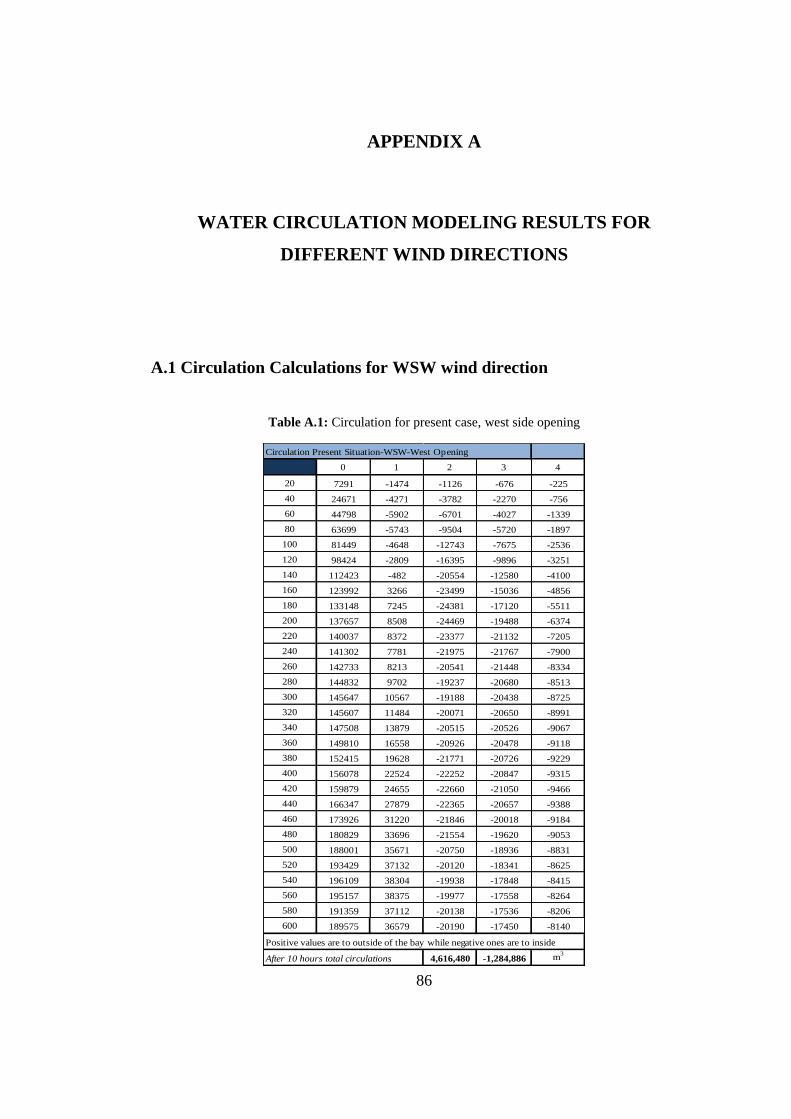
86
APPENDIX A
WATER CIRCULATION MODELING RESULTS FOR
DIFFERENT WIND DIRECTIONS
A.1 Circulation Calculations for WSW wind direction
Table A.1: Circulation for present case, west side opening
Circulation Present Situation-WSW-West Opening
0 1 2 3 4
20 7291 -1474 -1126 -676 -225
40 24671 -4271 -3782 -2270 -756
60 44798 -5902 -6701 -4027 -1339
80 63699 -5743 -9504 -5720 -1897
100 81449 -4648 -12743 -7675 -2536
120 98424 -2809 -16395 -9896 -3251
140 112423 -482 -20554 -12580 -4100
160 123992 3266 -23499 -15036 -4856
180 133148 7245 -24381 -17120 -5511
200 137657 8508 -24469 -19488 -6374
220 140037 8372 -23377 -21132 -7205
240 141302 7781 -21975 -21767 -7900
260 142733 8213 -20541 -21448 -8334
280 144832 9702 -19237 -20680 -8513
300 145647 10567 -19188 -20438 -8725
320 145607 11484 -20071 -20650 -8991
340 147508 13879 -20515 -20526 -9067
360 149810 16558 -20926 -20478 -9118
380 152415 19628 -21771 -20726 -9229
400 156078 22524 -22252 -20847 -9315
420 159879 24655 -22660 -21050 -9466
440 166347 27879 -22365 -20657 -9388
460 173926 31220 -21846 -20018 -9184
480 180829 33696 -21554 -19620 -9053
500 188001 35671 -20750 -18936 -8831
520 193429 37132 -20120 -18341 -8625
540 196109 38304 -19938 -17848 -8415
560 195157 38375 -19977 -17558 -8264
580 191359 37112 -20138 -17536 -8206
600 189575 36579 -20190 -17450 -8140
Positive values are to outside of the bay while negative ones are to inside
After 10 hours total circulations 4,616,480 -1,284,886 m3
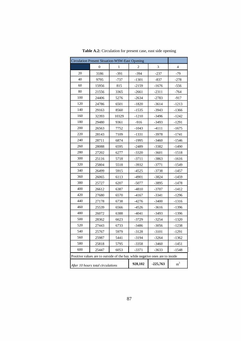
87
Table A.2: Circulation for present case, east side opening
Circulation Present Situation-WSW-East Opening
0 1 2 3 4
20 3186 -391 -394 -237 -79
40 9795 -737 -1301 -837 -278
60 15956 815 -2159 -1676 -556
80 21556 3365 -2661 -2311 -764
100 24406 5276 -2634 -2783 -917
120 24786 6501 -1820 -3614 -1213
140 29163 8560 -1535 -3943 -1366
160 32393 10329 -1210 -3496 -1242
180 29480 9361 -916 -3493 -1291
200 26563 7752 -1043 -4111 -1675
220 28143 7109 -1331 -3978 -1741
240 28711 6874 -1995 -3460 -1546
260 28088 6595 -2489 -3382 -1490
280 27202 6277 -3320 -3601 -1518
300 25116 5718 -3711 -3863 -1616
320 25804 5518 -3932 -3771 -1549
340 26499 5915 -4525 -3738 -1457
360 26065 6113 -4901 -3824 -1459
380 25727 6207 -5077 -3895 -1478
400 26612 6387 -4810 -3707 -1412
420 27680 6570 -4167 -3341 -1296
440 27178 6738 -4276 -3400 -1316
460 25539 6566 -4526 -3616 -1396
480 26072 6388 -4041 -3493 -1396
500 28362 6623 -3729 -3254 -1320
520 27443 6733 -3486 -3056 -1238
540 25767 5979 -3128 -3101 -1291
560 25987 5441 -3194 -3264 -1362
580 25818 5795 -3358 -3460 -1451
600 25447 6053 -3371 -3633 -1548
Positive values are to outside of the bay while negative ones are to inside
After 10 hours total circulations 928,102 -225,763 m3
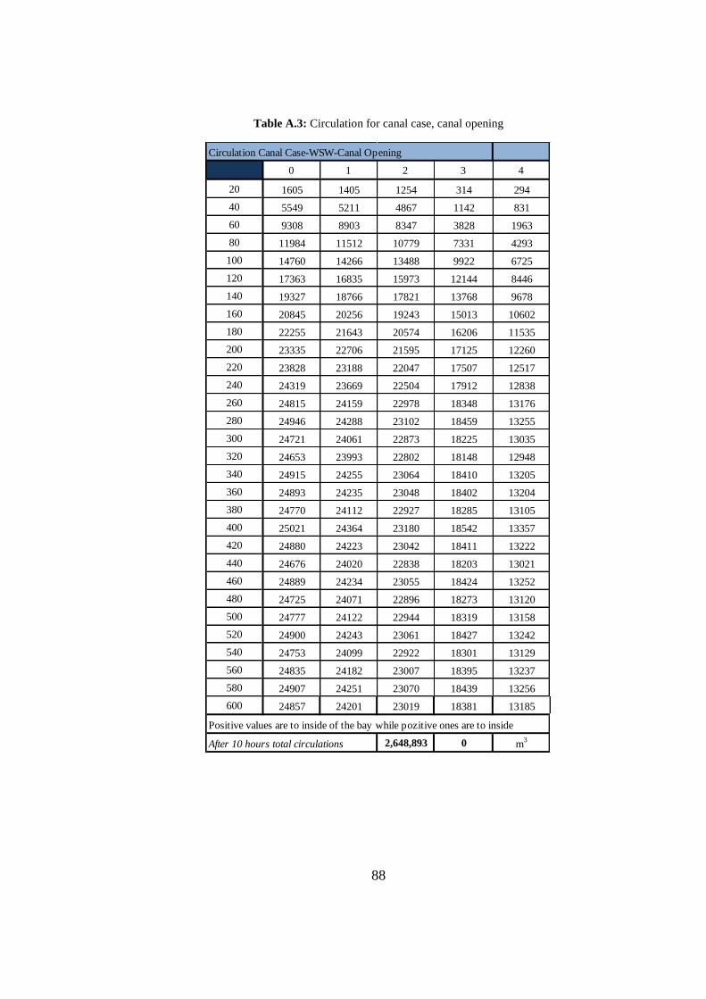
88
Table A.3: Circulation for canal case, canal opening
Circulation Canal Case-WSW-Canal Opening
0 1 2 3 4
20 1605 1405 1254 314 294
40 5549 5211 4867 1142 831
60 9308 8903 8347 3828 1963
80 11984 11512 10779 7331 4293
100 14760 14266 13488 9922 6725
120 17363 16835 15973 12144 8446
140 19327 18766 17821 13768 9678
160 20845 20256 19243 15013 10602
180 22255 21643 20574 16206 11535
200 23335 22706 21595 17125 12260
220 23828 23188 22047 17507 12517
240 24319 23669 22504 17912 12838
260 24815 24159 22978 18348 13176
280 24946 24288 23102 18459 13255
300 24721 24061 22873 18225 13035
320 24653 23993 22802 18148 12948
340 24915 24255 23064 18410 13205
360 24893 24235 23048 18402 13204
380 24770 24112 22927 18285 13105
400 25021 24364 23180 18542 13357
420 24880 24223 23042 18411 13222
440 24676 24020 22838 18203 13021
460 24889 24234 23055 18424 13252
480 24725 24071 22896 18273 13120
500 24777 24122 22944 18319 13158
520 24900 24243 23061 18427 13242
540 24753 24099 22922 18301 13129
560 24835 24182 23007 18395 13237
580 24907 24251 23070 18439 13256
600 24857 24201 23019 18381 13185
Positive values are to inside of the bay while pozitive ones are to inside
After 10 hours total circulations 2,648,893 0 m3
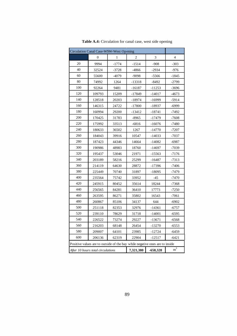
89
Table A.4: Circulation for canal case, west side opening
Circulation Canal Case-WSW-West Opening
0 1 2 3 4
20 9994 -1774 -1514 -908 -303
40 32524 -3728 -4866 -2934 -976
60 55600 -4079 -9098 -5566 -1845
80 74992 1264 -13318 -8492 -2799
100 92264 9481 -16187 -11253 -3696
120 109793 15209 -17849 -14017 -4673
140 128518 20203 -18974 -16999 -5914
160 146315 24722 -17800 -18937 -6999
180 160994 29200 -13412 -18741 -7492
200 170425 31783 -8965 -17479 -7608
220 175992 33513 -6816 -16076 -7480
240 180633 36502 1267 -14770 -7207
260 184043 39916 10547 -14033 -7037
280 187423 44346 14664 -14082 -6987
300 190986 48983 18760 -14697 -7039
320 195437 53046 21971 -15563 -7176
340 203189 58216 25299 -16487 -7313
360 214119 64630 28872 -17396 -7406
380 225449 70740 31897 -18095 -7479
400 235564 75742 33952 -45 -7470
420 245915 80452 35614 18244 -7368
440 256565 84281 36410 17773 -7250
460 263595 86271 35802 16543 -7061
480 260867 85106 34137 644 -6902
500 251118 82353 32976 -14361 -6757
520 239110 78629 31718 -14001 -6595
540 226522 73274 29227 -13671 -6568
560 216203 68148 26454 -13270 -6553
580 209007 64101 23985 -12724 -6459
600 206136 62319 22904 -12517 -6421
Positive values are to outside of the bay while negative ones are to inside
After 10 hours total circulations 7,321,380 -658,328 m3

90
Table A.5: Circulation for canal case, east side opening
Circulation Canal Case-WSW-East Opening
0 1 2 3 4
20 2948 -543 -454 -272 -91
40 9439 -1324 -1500 -904 -301
60 16162 -2090 -2782 -1680 -556
80 21162 528 -3986 -2449 -803
100 24356 4343 -4638 -3201 -1037
120 27028 5793 -4421 -4022 -1378
140 29285 6942 -3870 -4804 -1944
160 30811 7794 -3930 -5313 -2556
180 31959 8167 -4308 -5376 -2790
200 33007 8093 -4563 -5162 -2679
220 34062 8032 -4648 -4904 -2538
240 35159 8134 -4474 -4592 -2423
260 36019 8419 -4243 -4282 -2345
280 37483 8676 -4026 -4081 -2322
300 38664 8664 -3912 -4130 -2394
320 39646 8761 -3708 -4020 -2376
340 42088 9212 -3344 -3641 -2205
360 44203 9507 -3009 -3423 -2133
380 44340 9980 256 -3346 -2188
400 44415 10396 3468 -3355 -2197
420 44639 10604 3707 -3384 -2138
440 44500 10839 3848 -3338 -2098
460 44527 10986 3873 -3279 -2085
480 43790 11177 4268 -3502 -2164
500 43597 11347 4557 -3640 -2217
520 43552 11331 4676 -3777 -2260
540 42874 11353 4946 -3934 -2272
560 43346 11597 5064 -3857 -2187
580 43798 11999 5363 -3965 -2190
600 43479 12235 5601 -4081 -2228
Positive values are to outside of the bay while negative ones are to inside
After 10 hours total circulations 1,354,871 -238,584 m3

91
Table A.6: Circulation for dredged case, west side opening
Circulation Dredged Case-WSW-West Opening
0 1 2 3 4
20 7302 -1463 -1117 -670 -223
40 24785 -4176 -3713 -2229 -742
60 45006 -5681 -6557 -3941 -1311
80 63733 -5670 -9470 -5701 -1891
100 81626 -4522 -12651 -7621 -2519
120 99348 -2403 -15865 -9581 -3148
140 114065 629 -19551 -11981 -3904
160 125282 4564 -22636 -14512 -4688
180 133336 7695 -24154 -16966 -5468
200 138102 9264 -24089 -19256 -6303
220 140785 9445 -22823 -20819 -7102
240 142462 9284 -21217 -21341 -7760
260 143137 9167 -20164 -21245 -8271
280 143331 9334 -19872 -21072 -8651
300 144185 10708 -19888 -20853 -8869
320 146339 12950 -19822 -20431 -8918
340 149356 15767 -19787 -19971 -8880
360 150679 18283 -20869 -20289 -9045
380 153050 20926 -21689 -20546 -9164
400 157427 23560 -21646 -20354 -9149
420 162517 26532 -21829 -20256 -9168
440 168238 29514 -21884 -20090 -9164
460 174461 31979 -21609 -19754 -9088
480 181915 34829 -21342 -19265 -8911
500 189114 37053 -20851 -18694 -8708
520 195112 39206 -20770 -18223 -8503
540 197411 39695 -20278 -17709 -8315
560 195785 38638 -19685 -17325 -8187
580 193539 38371 -19797 -17031 -8010
600 192501 38269 -19718 -16763 -7876
Positive values are to outside of the bay while negative ones are to inside
After 10 hours total circulations 4,669,592 -1,265,687 m3
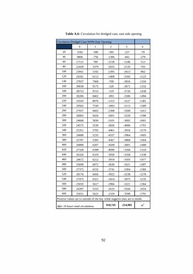
92
Table A.6: Circulation for dredged case, east side opening
Circulation Dredged Case-WSW-East Opening
0 1 2 3 4
20 3182 -390 -395 -237 -79
40 9806 -756 -1306 -841 -279
60 17131 789 -2158 -1546 -513
80 22439 3379 -2655 -2120 -702
100 23941 5182 -2395 -2613 -862
120 24181 6112 -1408 -3342 -1123
140 27837 7468 -768 -3816 -1334
160 30030 9175 -520 -3671 -1332
180 28753 9155 -519 -3726 -1438
200 30206 8402 -893 -3586 -1494
220 31010 8076 -1315 -3127 -1381
240 29562 7330 -1893 -3113 -1389
260 27937 6602 -2308 -3208 -1413
280 26802 6426 -2601 -3228 -1396
300 24668 5830 -3101 -3692 -1601
320 24575 5530 -3826 -4006 -1701
340 25351 5705 -4461 -3916 -1570
360 24680 5235 -4337 -3964 -1605
380 25787 5395 -4367 -3868 -1564
400 26800 6207 -4509 -3601 -1408
420 27328 6398 -4090 -3344 -1318
440 26326 6319 -3950 -3358 -1338
460 24672 6212 -3919 -3593 -1477
480 25699 6072 -3630 -3521 -1497
500 27375 6232 -3741 -3304 -1360
520 28176 6456 -3922 -3238 -1278
540 27475 6321 -3414 -3075 -1235
560 25010 5617 -2966 -3221 -1364
580 24397 5333 -2633 -3544 -1654
600 25031 5622 -2329 -3598 -1791
Positive values are to outside of the bay while negative ones are to inside
After 10 hours total circulations 918,745 -214,985 m3