Embed Size (px)
Citation preview
TOMMI PAANU SEPPO NIEMI
PEKKA RANTANEN
Waste Heat Recovery – Bottoming Cycle Alternatives
PROCEEDINGS OF THE UNIVERSITY OF VAASA ___________________________________________
REPORTS 175
VAASA 2012

Vaasan yliopisto – University of Vaasa PL 700 – P.O. Box 700 (Wolffintie 34)
FI–65101 VAASA Finland
www.uwasa.fi
ISBN 978–952–476–389–9 ISSN 1238–7118 = Proceedings of the University of Vaasa. Reports © University of Vaasa
III
Contents 1 Introduction ............................................................................................... 1 2 Background and some definitions ............................................................... 2 3 Steam Rankine cycle as a bottoming cycle ................................................. 4 4 Organic Rankine cycle ............................................................................... 4 5 The Kalina cycle ........................................................................................ 5 6 Trilateral Flash Cycle ................................................................................. 9 7 Comparisons between steam Rankine, ORC, Kalina and TFC cycles ........ 11 8 Supercritical CO2 Rankine cycle ............................................................... 13 9 Gas bottoming cycles: Stirling-engine ...................................................... 15 10 Gas bottoming cycles: Brayton ................................................................. 16 11 Hydrogen fuelled internal combustion engine........................................... 17 12 LNG vaporization as a Rankine cycle heat sink ........................................ 18 13 Conclusions ............................................................................................. 19 14 Recommendations .................................................................................... 20 References ........................................................................................................ 21
Figures
Figure 1. Thermodynamic cycles and their temperature range, after (Korobitsyn, 1998) .................................................................. 3 Figure 2. A schematic of a simple ORC, after (Chen 2011). ........................... 4 Figure 3. Flow scheme of the basic Kalina cycle, after (Korobitsyn 1998) ...... 5 Figure 4. Ammonia-water phase diagram, after (MLCAK 1996) .................... 6 Figure 5. Energy recuperation from turbine exhaust to feed mixture, after (MLCAK 1996) ...................................................................... 7 Figure 6. Husavik geothermal power plant diagram, after (Valdimarsson 2003) ............................................................... 9 Figure 7. The configuration of a trilateral flash cycle, after (Chen 2011) ...... 10 Figure 8. The principal diagram of the solar-powered Rankine cycle, after (Yamaguchi et al. 2006) ........................................................ 13 Figure 9. The cycle studied by Yamaguchi et al. (2006) in the p–h (a) and T–s (b) diagrams, after (Yamaguchi et al. 2006) ..................... 14 Figure 10. An open steam Rankine cycle using condensed water from HICE exhaust gas as a working fluid, after (Yamada & Mohamad 2010) ............................................................................ 17
Tables
Table 1. Comparison between TFC, four ORC’s and a Kalina cycle, after (Zamfirescu & Dincer 2008) ................................................. 12

IV
Abbreviations
ABC Air Bottoming Cycle CO2 Carbon dioxide CHP Combined Heat and Power DCSS Distillation Condensation Subsystem EGR Exhaust Gas Recirculation FCEP Future Combustion Engine Power Plant HICE Hydrogen Internal Combustion Engine HRVG Heat Recovery Vapor Generator LNG Liquefied Natural Gas NOx Nitrogen Oxides ORC Organic Rankine Cycle TFC Trilateral Flash Cycle WHR Waste Heat Recovery
1 Introduction
Based on its high efficiency, the diesel engine is the leading power source for several heavy-duty applications, such as marine installations, electricity produc-tion, on-road trucks and buses, and various off-road machines. Inherently, the high efficiency means low carbon dioxide (CO2) emissions. Still today, one of the global challenges over the whole energy field is to further reduce greenhouse gas emissions to combat climate change, including the reduction of the CO2 emis-sions. This can be achieved by increasing the energy efficiency and energy sav-ings, and by finding renewable options instead of conventional fossil energy sources. In this respect, the diesel engine provides a good starting point with a potential to achieve substantial improvements both in energy efficiency and emis-sions reduction. (FCEP 2010)
Within the ongoing large Finnish research program Future Combustion Engine Power Plant (FCEP), one of the work packages concentrates on the energy effi-ciency of internal combustion engines. Technologies related to the improvement of energy efficiency are developed. The engine itself, waste heat recovery (WHR) systems, or power conversion are investigated.
This study was part of the FCEP research program and focused particularly on the waste heat recovery systems with a target to find feasible solutions to increase the electricity production of diesel and gas engine driven power plants. At the same time, energy efficiency is improved, decreasing CO2 emissions.
Diesel engines, due to their high combustion temperature and pressure, provide an energy conversion technology that is more efficient than any other thermal power device. Especially within the medium-speed range, large diesel and gas engines can reach electrical efficiencies of more than 45%. Nevertheless, the environmen-tal concerns and increasing fuel prices push for continuous improvement in the energy efficiency. The WHR systems are seen as one of the most promising tech-nologies to improve the efficiency of current diesel and gas engine installations significantly.
The aim of this study was to search for and find thermodynamic processes and power conversion methods which could be applied as a WHR system in combina-tion with diesel and gas engines to produce additional electrical power from the excess heat. Below, these processes and methods are briefly described and their practical potential is discussed. The study is mainly based on literature data col-lected in the University of Vaasa.

2 Proceedings of the University of Vaasa. Reports
2 Background and some definitions
Within waste heat recovery technology, the terms bottoming cycle, topping cycle, and combined cycle are used. A bottoming cycle is a thermodynamic cycle which generates electricity from waste heat, as opposed to a topping cycle, in which waste heat from electricity generation is rejected to the environment (cooling wa-ter, atmosphere), or used for heating purposes in industry or for district heating purposes (cogeneration). In a combined cycle these cycles are combined for elec-tricity production by connecting two heat engines in series. (El-Wakil 1984)
Some basic cycles have a maximum temperature closer to the fuel flame tempera-ture, but a rather high temperature of heat rejection. Others reject heat at nearly ambient temperature, but possess a moderate maximum temperature. Therefore, in order to approach higher efficiency, a combined cycle is required with a high-temperature topping cycle and a medium- or low-temperature bottoming cycle. Combined cycles are mostly considered as dual cycles, since the complexity of triple-cycles, such as the potassium-steam-organic Rankine cycle, is undesirable. (Korobitsyn 1998)
The drawback of one cycle may become a benefit when combined with another cycle. The high exhaust temperature of a gas turbine indicates its low efficiency, but is advantageous for the steam bottoming cycle. The highly efficient aero-derivative gas turbines provide worse performance in a combined cycle configu-ration than industrial turbines with lower efficiency and higher exhaust tempera-tures. (Korobitsyn 1998)
To determine what cycle is better suited for a topping or bottoming application, cycles can be ranked according to their operating temperature range (Figure 1). (Korobitsyn 1998)

Proceedings of the University of Vaasa. Reports 3
Figure 1. Thermodynamic cycles and their temperature range, after (Koro-bitsyn, 1998)
Of the various combined cycles, the Joule (Brayton) and steam Rankine combined cycle is the most developed and wide-spread. Inexpensive and readily available media, such as air for the topping cycle, and water/steam for the bottoming cycle, and well-developed technologies (gas turbine, waste heat boiler, steam turbine) have led to wide acceptance of this configuration. (Korobitsyn 1998) The term Combined gas and steam turbine power plant is often used in this context.
Regardless of their high brake thermal efficiencies, diesel and gas engines also produce waste heat. Basically, there are four engine waste heat streams that can be recovered by a bottoming cycle:
exhaust gas
charge air
jacket water, and
lubricating oil. (Jonsson & Yan 2001)
The waste heat rejected through the exhaust gas represents a large fraction of the fuel’s energy (Taylor, 2008). Several modern diesel engines are equipped with exhaust gas recirculation (EGR) to control NOx emissions. High EGR rates re-quire effective cooling of recirculated gas. This heat rejection has a temperature level suitable for an effective WHR system. (Teng et al, 2011) Suitable bottoming cycles for diesel and gas engine are the Rankine, Brayton, Kalina, and Stirling cycles (Korobitsyn 1998).
4 Proceedings of the University of Vaasa. Reports
3 Steam Rankine cycle as a bottoming cycle
Combined cycle technology, based on gas turbine topping and the steam Rankine bottoming cycle, is likely to remain attractive for many years. Electrical efficien-cies of up to 58% can be achieved with plant capacities within the range of 350 to 500 MW of electrical power. (Poullikkas 2005)
The exhaust gas from an Otto/Diesel engine has a temperature of 300–500 °C and, thus, exhaust heat can be recovered in a waste heat boiler. However, the en-gine releases a smaller amount of exhaust gases than a comparable gas turbine, because it does not require any considerable air flow for cooling. The excess air for a diesel engine is typically 30–40%, compared to 200–350% for a gas turbine. Hence a 10 MW engine can provide about 1–1.5 MW of electric power by means of the bottoming steam Rankine cycle. Moreover, the performance of the Rankine cycle rapidly declines when the exhaust temperature is decreased. (Korobitsyn 1998)
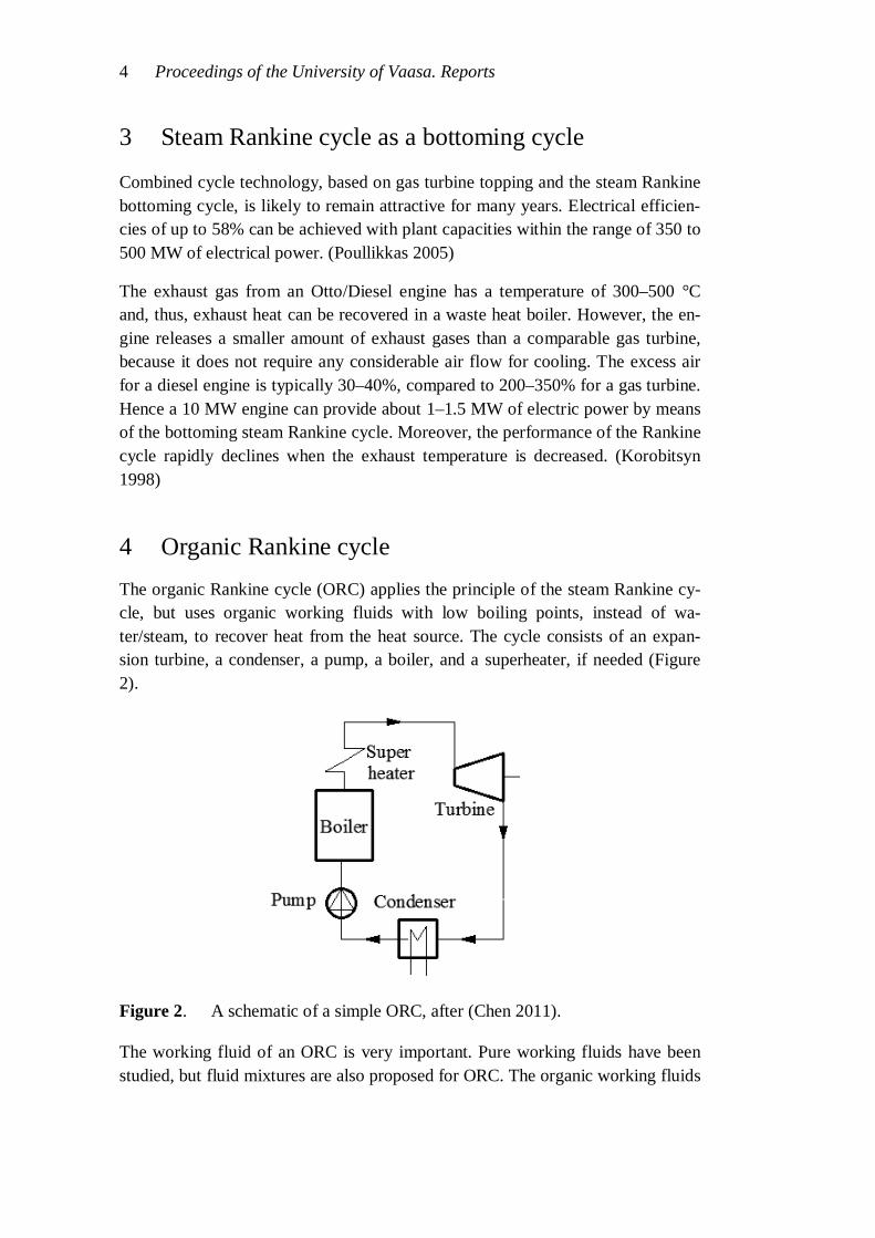
4 Organic Rankine cycle The organic Rankine cycle (ORC) applies the principle of the steam Rankine cy-cle, but uses organic working fluids with low boiling points, instead of wa-ter/steam, to recover heat from the heat source. The cycle consists of an expan-sion turbine, a condenser, a pump, a boiler, and a superheater, if needed (Figure 2).
Figure 2. A schematic of a simple ORC, after (Chen 2011).
The working fluid of an ORC is very important. Pure working fluids have been studied, but fluid mixtures are also proposed for ORC. The organic working fluids
Proceedings of the University of Vaasa. Reports 5
have many different characteristics than water. An ORC plant typically requires only a single-stage expander, resulting in asimpler and more economical system in terms of capital costs and maintenance.
Among all thermodynamic cycles for low-grade heat power conversion, the ORC is so far the commercially most developed one. Both large scales and small scales power plants and units can be found in operation. (Chen 2011)
In this study the ORC is not enlarged on, except as a comparison for other cycles.
5 The Kalina cycle The Kalina cycle is principally a “modified” Rankine cycle or rather, a reversed absorption cycle (Valdimarsson, 2003). The Kalina cycle uses a mixture as the working fluid, instead of a pure fluid like water, the mixture being composed of at least two different components, typically water and ammonia (Chen 2011).
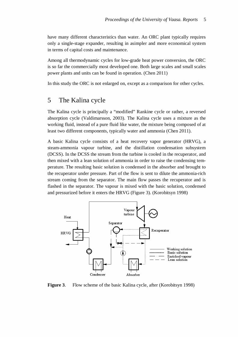
A basic Kalina cycle consists of a heat recovery vapor generator (HRVG), a steam-ammonia vapour turbine, and the distillation condensation subsystem (DCSS). In the DCSS the stream from the turbine is cooled in the recuperator, and then mixed with a lean solution of ammonia in order to raise the condensing tem-perature. The resulting basic solution is condensed in the absorber and brought to the recuperator under pressure. Part of the flow is sent to dilute the ammonia-rich stream coming from the separator. The main flow passes the recuperator and is flashed in the separator. The vapour is mixed with the basic solution, condensed and pressurized before it enters the HRVG (Figure 3). (Korobitsyn 1998)
Figure 3. Flow scheme of the basic Kalina cycle, after (Korobitsyn 1998)

6 Proceedings of the University of Vaasa. Reports
A mixture of two fluids behaves differently from the two fluids separately. A mixture of water and ammonia has a varying boiling and condensing temperature. The properties of the water-ammonia mixture can be altered by changing the am-monia concentration. Water freezes at a temperature of 0°C, pure ammonia at -78°C. Solutions of ammonia-water have very low freezing temperatures. (MLCAK 1996)
Ammonia has a low boiling and condensing temperature compared to water. Therefore, ammonia in a mixture with water is the more volatile component of the two. When an ammonia-water liquid is heated, mostly ammonia will boil off first, i.e. distillation will start to occur. Conversely, mostly water will condense first. This unique feature is illustrated in a phase diagram in Figure 4. In this diagram, the x-axis represents the percentage of ammonia in an ammonia-water solution. (MLCAK 1996)
Figure 4. Ammonia-water phase diagram, after (MLCAK 1996)
By way of example, consider a 70 % liquid ammonia (in water) mixture, common in the Kalina cycle. The saturated mixture starts to vaporize at 21°C. During heat-ing, the temperature rises and more of the mixture, mostly ammonia at first, boils off. For example, at 66°C, the 70 % average solution is shown at point 4. The vapor component (97 % ammonia, 3 % water) of this solution is shown at point 5 and the liquid component (36 % ammonia, 64 % water) at point 6. Vaporization continues until all of the mixture reaches a dry saturated vapor state at 116°C, point 7. This process is completely reversed.
The use of a mixture results in a good thermal match in the boiler or counter-flow heat exchanger due to the variable temperature (non-isothermal) boiling created
Proceedings of the University of Vaasa. Reports 7
by the shifting mixture composition. This decreases the thermodynamic irreversi-bility in heat transfer and therefore improves the overall thermodynamic efficien-cy. (Chen 2011) However, the thermodynamic advantage of this small boiler temperature difference compared to a steam cycle would be lost at the condensing stage, assuming the same condenser cooling water temperature in both cases. (Poullikkas 2005)
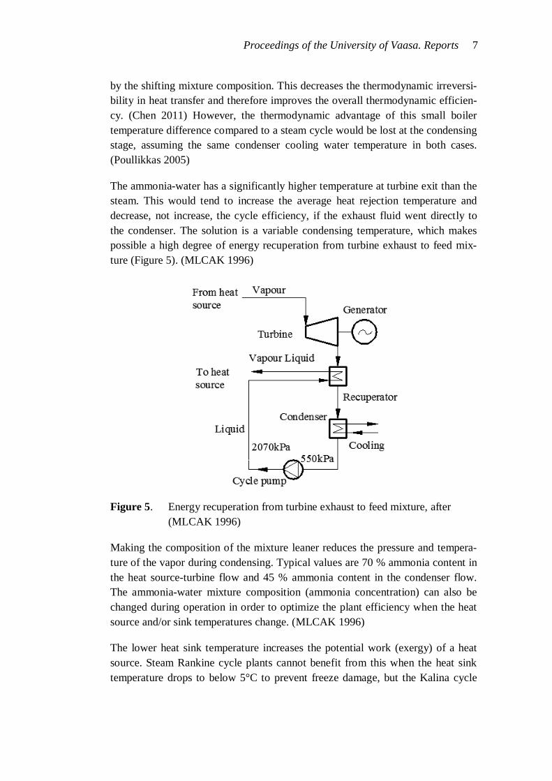
The ammonia-water has a significantly higher temperature at turbine exit than the steam. This would tend to increase the average heat rejection temperature and decrease, not increase, the cycle efficiency, if the exhaust fluid went directly to the condenser. The solution is a variable condensing temperature, which makes possible a high degree of energy recuperation from turbine exhaust to feed mix-ture (Figure 5). (MLCAK 1996)
Figure 5. Energy recuperation from turbine exhaust to feed mixture, after (MLCAK 1996)
Making the composition of the mixture leaner reduces the pressure and tempera-ture of the vapor during condensing. Typical values are 70 % ammonia content in the heat source-turbine flow and 45 % ammonia content in the condenser flow. The ammonia-water mixture composition (ammonia concentration) can also be changed during operation in order to optimize the plant efficiency when the heat source and/or sink temperatures change. (MLCAK 1996)
The lower heat sink temperature increases the potential work (exergy) of a heat source. Steam Rankine cycle plants cannot benefit from this when the heat sink temperature drops to below 5°C to prevent freeze damage, but the Kalina cycle
8 Proceedings of the University of Vaasa. Reports
can. Ammonia has a very low freezing temperature. As a result, condensation temperatures of ammonia-water fluids can go down to arctic temperatures by ap-plying air cooled condensers. (MLCAK 1996)
Conventional axial flow steam turbines can be used in Kalina cycle plants. This is possible because the molecular weights of ammonia and water are at the same scale (ammonia 17 g/mol and water 18 g/mol). (MLCAK 1996) Because the ex-haust pressure of the vapor turbine in the Kalina cycle is above atmospheric pres-sure, no vacuum needs to be maintained in the condenser during operation, or stand-by periods. Therefore, the start-up procedure can be performed within a much shorter time. (Korobitsyn 1998; Poullikkas 2005) Higher back pressure also creates a big difference in specific volumes and therefore a big difference in the size of the flow area in the exhausting turbine. Therefore, turbines for Kalina cy-cle plants will also be smaller and less expensive because the cycle can utilize back pressure turbines as condensing turbines. (MLCAK 1996)
Chen (2011) states that the Kalina cycle performs substantially better than a steam Rankine cycle. The Kalina cycle can produce 10–30% more power than a steam Rankine cycle. Another advantage is the smaller size of the whole unit. The foot-print of the Kalina plant is about 60% of the size of a steam Rankine plant design. (Korobitsyn 1998; Poullikkas 2005)
According to Korobitsyn (1998), at the same top temperature of 650 °C, the Ka-lina cycle will obtain approximately 20 % greater efficiency than the triple-pressure steam Rankine cycle, while the former does not require such high pres-sure.
A Kalina cycle power plant may offer efficiency gains of up to 50 % for low heat energy sources such as geothermal brine at 150°C to 210°C. Gains of up to 20 % may be realized for higher temperature heat sources such as the exhaust gas bot-toming cycle of a combined cycle plant. It is estimated that Kalina cycle plants will even cost less to build than Rankine cycle plants of equal output. Up to 30 % savings for low heat applications and up to 10 % savings for bottoming cycle plants have been approximated. (MLCAK 1996)
One drawback of the Kalina cycle is the fact that a high vapor fraction is needed in the boiler, resulting in lower overall heat transfer coefficients and a larger heat exchange area. Another drawback relates to the corrosion. Impurities such as air or carbon dioxide in liquid ammonia may cause stress corrosion cracking of mild steel. Ammonia is also highly corrosive towards copper and zinc (Chen 2011).

Proceedings of the University of Vaasa. Reports 9
The Kalina cycle has many designs, somewhat analogous to the Rankine cycle which has many design options such as reheat, regenerative heating, supercritical cycle, dual pressure, etc. Each Kalina cycle design has a specific application for different heat sources, such as gas turbine combined cycles or low temperature geothermal plants. (MLCAK, 1996) The Kalina Cycle trademark and patents are owned by Global Geothermal Ltd (Chen 2011).
Kalina references are listed by (Valdimarsson 2003):
Canoga Park, USA, demonstration plant 3 – 6 MW
Fukuoka, Japan, incineration plant, 4.5 MW
Sumitomo, Japan, waste heat recovery from a steel plant, 3.1 MW
Husavik, Iceland, geothermal plant, 2.0 MW (Figure 6).
Figure 6. Husavik geothermal power plant diagram, after (Valdimarsson 2003)
The net electrical efficiency of 11 % for the Husavik plant is reported by Val-dimarsson (2003). Valdimarsson (2003) also gives a budgetary price of USD 720,000 for the 500 kW Kalina unit, which equals 1440 USD/kW.
6 Trilateral Flash Cycle
The Trilateral Flash Cycle (TFC) is a thermodynamic power cycle whose expan-sion starts from the saturated liquid state rather than a vapor phase. By avoiding the boiling part, the heat transfer from a heat source to a liquid working fluid is
10 Proceedings of the University of Vaasa. Reports
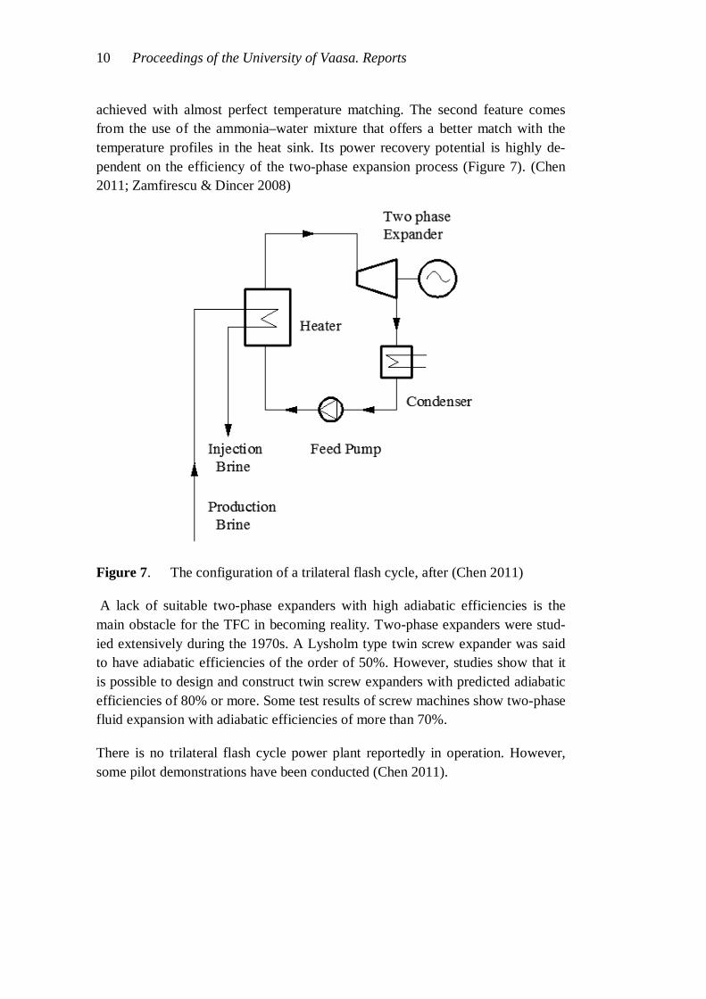
achieved with almost perfect temperature matching. The second feature comes from the use of the ammonia–water mixture that offers a better match with the temperature profiles in the heat sink. Its power recovery potential is highly de-pendent on the efficiency of the two-phase expansion process (Figure 7). (Chen 2011; Zamfirescu & Dincer 2008)
Figure 7. The configuration of a trilateral flash cycle, after (Chen 2011)
A lack of suitable two-phase expanders with high adiabatic efficiencies is the main obstacle for the TFC in becoming reality. Two-phase expanders were stud-ied extensively during the 1970s. A Lysholm type twin screw expander was said to have adiabatic efficiencies of the order of 50%. However, studies show that it is possible to design and construct twin screw expanders with predicted adiabatic efficiencies of 80% or more. Some test results of screw machines show two-phase fluid expansion with adiabatic efficiencies of more than 70%.
There is no trilateral flash cycle power plant reportedly in operation. However, some pilot demonstrations have been conducted (Chen 2011).
Proceedings of the University of Vaasa. Reports 11
7 Comparisons between steam Rankine, ORC, Kalina and TFC cycles Jonsson & Yan (2001) have studied the differences between Kalina-type bottom-ing cycle configurations designed for different gas engine and gas diesel engine types. One of their key focuses was to demonstrate the potential of the Kalina cycle to produce more power than the Rankine cycle as an engine bottoming cy-cle. Four different power plant configurations were studied, all based on Wärtsilä engines with gas engine models 16V25SG and 18V34SG and gas diesel engine models 18V32GD and 18V46GD.
The characteristics of the heat sources differ for the four engine models and the optimal Kalina cycle configuration is unique to the engine. Cycle configurations that use all engine heat sources are complex and include many heat exchangers. Low heat source temperatures should be to the advantage of the Kalina cycle rela-tive to the Rankine cycle. In most cases the gas engine with a Kalina bottoming cycle produces more power compared to the Rankine cycles than the gas diesel engine. The Kalina cycle can use more of the heat in the exhaust gas stream than the Rankine cycle.
Both Bombarda et al. (2010) and Valdimarsson (2003) have compared the Kalina and ORC cycles. The OCR model (Valdimarsson 2003) is based on a system without regeneration. Isopenthane is assumed as the working fluid. A saturated vapor Kalina cycle is used. As a result, the maximum power generated for a given source is greater for the Kalina cycle. The Kalina cycle is well positioned against an ORC for a base load application. The Kalina is better than the ORC when the heat source stream has finite heat capacity, but similar when the source is con-densing steam (constant temperature).
Bombarda et al. (2010) compared the thermodynamic performance of the Kalina cycle and ORC (hexamethyldisiloxane as working fluid) in the case of heat re-covery from two Wärtsilä 20V32 8.9 MW diesel engines with exhaust gas mass flow of 35 kg/s for both engines, at 346ºC. In order to facilitate the comparison, only the heat recovery from the exhaust gases was considered. An almost equal net electric power of 1615 kW (with a cycle efficiency of 19.7 %) and of 1603 kW (with cycle efficiency of 21.5 %) for the Kalina and ORC cycles was calcu-lated, respectively. In this case, the Kalina cycle requires a very high maximum pressure in order to obtain high thermodynamic performances: 100 bar against the about 10 bar of the ORC cycle. The turbine design also favours the ORC cycle, as the isentropic enthalpy drop is definitely higher for the Kalina (575 kJ) than for the ORC (92 kJ). For the Kalina cycle, the required turbine rotational speed is very high (> 60000 rpm) thus requiring a gear box, and therefore adding gearbox

12 Proceedings of the University of Vaasa. Reports
losses. The use of the Kalina cycle for medium and high temperature thermal sources seems unjustified because there is no gain in performance instead, a com-plicated plant scheme, large surface heat exchangers and corrosion resistant mate-rials, such as titanium in the turbine, result.
Zamfirescu & Dincer (2008) have compared the TFC, four ORCs and a Kalina cycle, all operating under the same conditions in the both heat sink and source. The same flow rate and temperature at source inlet and an isentropic efficiency of 70 % for the expander were assumed. Cycle pressures were selected to maximize exergy efficiency for each fluid. The cycle efficiencies ( ), power outputs (P) and heat inputs (Q) are listed in Table 1.
Table 1. Comparison of TFC, four ORCs and a Kalina cycle, after (Zam-firescu & Dincer 2008)
Cycle (fluid) (%) P (kW) Q (kW)
ORC (R141b) 10 13 132
ORC (R123) 9 17 179
ORC (R245ca) 9 18 189
ORC (R21) 9 18 198
Kalina (NH3–H2O) 3 13 373
TFC (NH3–H2O) 8 38 477
An ORC with R141b has the highest efficiency of 10 %, but extracts the least heat from the source, while the trilateral flash cycle receives the most, i.e., 3.6 times more. The TFC uses the most of the source’s exergy because both the source fluid (water) and the working fluid (ammonia–water) are in liquid state and have simi-lar specific heats, and thus the temperature difference in the heat exchanger is minimized. Since the source stream exergy is fixed, the cycle that converts the most of it into work (or useful exergy) is the best. The TFC recovers the most of the source’s exergy (93 %), the Kalina cycle being the second best (76 %).
Teng et al. (2011) have studied a Rankine cycle based WHR system for a modern heavy duty truck diesel engine. The primary WHR heat source was EGR cooling. Four working fluids, R245fa (C3H3F5), ethanol (C2H5OH), water and water-ethanol mixture were chosen as candidates for the comparison. Ethanol was se-

Proceedings of the University of Vaasa. Reports 13
lected, based on its thermodynamic properties and profitable cost level. An up to 5 % improvement in engine fuel efficiency is possible by utilizing ORC in their case.
8 Supercritical CO2 Rankine cycle
Carbon dioxide CO2 (R-744) is a natural working fluid; inexpensive, non-explosive, non-flammable, and non-toxic. Its critical pressure and temperature are 73.8 bar and 31.1ºC, respectively. (Yamaguchi et al. 2006; Wang et al. 2006)
Working fluids with relatively low critical temperature and pressure can be com-pressed directly to their supercritical pressures and heated to their supercritical state before expansion. The heating process of a supercritical Rankine cycle does not pass through a distinct two-phase region like a conventional steam Rankine cycle, thus getting a better thermal match in the boiler with less irreversibility. (Chen 2011) A supercritical CO2 power cycle shows high potential for recovering low-grade waste heat. (Wang et al. 2006)
Yamaguchi et al. (2006) propose a supercritical CO2 Rankine cycle for solar ener-gy production. The system utilizes evacuated solar collectors to convert CO2 into high temperature supercritical state, used to drive a turbine and thereby produce mechanical energy and hence electricity (Figure 8).
Figure 8. The principal diagram of the solar-powered Rankine cycle after (Yamaguchi et al. 2006)

14 Proceedings of the University of Vaasa. Reports
A solar collector is used to heat the CO2 contained in the heating channels. This heat transfer process results in the trans-critical cycle, i.e. with subcritical low-side and supercritical high-side pressure. The supercritical CO2 drives the turbine, and hence, the connected electrical generator. After leaving the high- and low-temperature heat recovery system, the CO2 is cooled to a liquid state and pumped back into the higher pressure condition. (Yamaguchi et al. 2006)
Because of the high temperature in the solar collector, this CO2-based Rankine cycle would have to operate in the transcritical cycle most of the time, i.e. with heat absorption above the critical temperature and supercritical high-side pres-sure. However, the low-side conditions would remain subcritical (Figure 9). (Ya-maguchi et al. 2006)
Figure 9. The cycle studied by Yamaguchi et al. (2006) in the p–h (a) and T–s (b) diagrams, after (Yamaguchi et al. 2006)
An experimental prototype has been designed, constructed and tested under typi-cal summer conditions in Kyoto, Japan. The experimental results showed that the solar energy powered Rankine cycle using CO2 works stably in a transcritical region. The time-averaged power generation efficiency was found to be 25 %. In a previous theoretical study, the annual averaged power generation efficiency was calculated to be 22 %. A comparison shows that the theoretical predictions are close to the measurement values. (Yamaguchi et al. 2006)

Proceedings of the University of Vaasa. Reports 15
Supercritical CO2 has physical properties somewhere between those of a liquid and a gas. To date, there is no turbine available for the supercritical CO2 cycle. Therefore, in this prototype, a throttling valve was used, instead of a turbine. (Yamaguchi et al. 2006)
Organic fluids have also been suggested for the supercritical Rankine cycle. The CO2 supercritical power cycle has slightly higher system efficiency than an ORC (using R123) when taking into account the behavior of the heat transfer between the heat source and the working fluid. The CO2 cycle shows no pinch limitation in the heat exchanger. However, detailed studies on the use of organic working flu-ids in supercritical Rankine cycles have not been widely published. (Chen 2011; Wang et al. 2006)
Besides some CO2 Brayton cycle research for power production in the nuclear reactor area, there is little information available for power cycle research with CO2 as the working fluid in the low-grade small-scale energy utilization area. (Wang et al. 2006)
9 Gas bottoming cycles: Stirling-engine
A Stirling cycle machine is a device which operates on a closed regenerative thermodynamic cycle, with cyclic compression and expansion of the working fluid at different temperature levels (Thombare & Verma 2008). The cycle medi-um (generally helium or hydrogen) is not exchanged during each cycle, while the energy driving the cycle is applied externally (Wu & Wang 2006). The Stirling engines are frequently called by other names, including hot-air or hot-gas engines. High heat efficiency, low noise operation and the ability of Stirling engines to use many fuels are said to meet the demands for the effective use of energy and envi-ronmental security. For successful operation of a Stirling engine with good effi-ciency, careful design of heat exchangers (especially the regenerator) and proper selection of drive mechanism and engine configuration are essential. (Thombare & Verma 2008)
Stirling engines are a promising solution for installations with nominal electric output between 10 and 150 kW (Obernberger et al. 2003). The power output of a Stirling engine is directly proportional to the mean cycle pressure. To obtain high power levels and densities, pressures in the range of 100-200 bar are used. The Stirling cycle engines can achieve efficiencies of 65-70 % of the Carnot cycle efficiency with current technology. (Thombare & Verma, 2008)
16 Proceedings of the University of Vaasa. Reports
Today, Stirling cycle-based systems are in commercial use as a heat pump, and in cryogenic refrigeration and air liquefaction. As a prime mover, Stirling cycles remain the subject of research and development efforts. (Thombare & Verma 2008) High cost also prevents popularization of this technology (Wu & Wang 2006).
Poullikkas (2005) has estimated that 9.0 MW of electrical power can be recovered by a bottoming Stirling cycle from the exhaust of a Rolls–Royce RB211 gas tur-bine generating 27.5 MW of electrical power. This means 33 % additional power. Such a plant could obtain a total electrical efficiency of 48 %
Vlaskos et al. (2010) have simulated the Stirling engine cycle as a bottoming cy-cle for a diesel engine. A hypothetical 5000 kW diesel engine was assumed to compare different options for exhaust gas heat recovery. 12- and 16-cylinder, low speed Stirling engines were simulated. The simulation with the 16-cylinder, 72 l version showed the following characteristics: shaft power 740 kW (600 rpm), overall efficiency 27%. The combined output was then increased from 5000 kW to 5740 kW without additional fuel consumption, improving the specific fuel oil consumption by 12.9%, from 181 to 157 g/kWh.
Obernberger et al. (2003) report the Stirling engine technology as of high interest for a small-scale biomass CHP plant. A 35 kW Stirling engine especially designed for CHP plants using biomass fuels was developed at the Technical University of Denmark. The engine has four cylinders arranged in a square with the cylinders parallel to each other. Helium is used as the working gas at a maximum mean pressure of 45 bar. The plant was put into operation in summer 2002 and compre-hensive test runs had been performed by spring 2003. The average electric power output of 31 kW was less than expected. The achieved electrical efficiency was 20%, lower than the expected 25%).
10 Gas bottoming cycles: Brayton
An air bottoming cycle (ABC) was proposed in the late 1980s as an alternative for the conventional steam bottoming cycle (Korobitsyn 2002). The Brayton cycle can be used as a bottoming cycle for the gas turbine by means of a gas–gas heat exchanger. In contrast to the conventional combined cycle, this alternative does not require bulky steam equipment (boiler, steam turbine, condenser, etc.), and allows unmanned operation. An increase in power of 18–30% and in efficiency of up to 10%-units is expected in a gas turbine with Brayton bottoming cycle de-pending on the number of intercoolers. (Poullikkas 2005; Korobitsyn 1998)

Proceedings of the University of Vaasa. Reports 17
For example, the Allison 571K topping gas turbine, introduced with the air bot-toming cycle, incorporating two intercoolers, led to an increase in power from 5.9 to 7.5 MW and in efficiency from 33.8 to 43.2 %. Comparable results were ob-tained with the General Electric LM2500 topping turbine. (Korobitsyn 1998)
In a closed Brayton cycle an alternative working gas, such as helium or CO2, can be used. (El-Wakil 1984)
11 Hydrogen fuelled internal combustion engine Exhaust gas from the hydrogen internal combustion engine (HICE) contains mainly water vapour. This exhaust stream is condensed to (liquid) water when used as a heat source for a waste heat recovery system. This condensed water is pumped to a boiler, where it is evaporated and superheated, and is used to pro-duce power in a steam expander. A classical locomotive steam engine is an ex-ample of an open Rankine cycle. (Yamada & Mohamad 2010)
An open steam Rankine cycle subsystem consists of five main components: water separator, tank, pump, evaporator, and expander. In the evaporator, the water is boiled and superheated. This superheated vapor expands in the expander. Low pressure vapor leaving the expander is released to the atmosphere (Figure 10). (Yamada & Mohamad 2010)
Figure 10. An open steam Rankine cycle using condensed water from HICE exhaust gas as a working fluid, after (Yamada & Mohamad 2010)
18 Proceedings of the University of Vaasa. Reports
According to the study by Yamada & Mohamad (2010), a recovery subsystem without a condenser is a better choice. The HICE overall thermal efficiency was 3-4 %-units higher than that of a conventional HICE without any recovery sub-system. The water consumption in the recovery subsystem exceeded the amount produced by the water separator at a separator efficiency of 50%. Hence, further research on water separators must be conducted for the realization of the proposed system.
12 LNG vaporization as a Rankine cycle heat sink
Liquefied natural gas (LNG) is in general the only viable way to transport gas over the oceans. At the receiving gas terminal, the temperature of the LNG is low (-162ºC) in the storage tanks. The LNG has to be heated to vaporize it before it enters the delivery piping. Typically sea water is used as the heat source to vapor-ize LNG. This process not only consumes a large amount of power for driving the sea water pump but also wastes cold energy.
The system proposed by Shi & Che (2007) uses this LNG vaporization as a low-temperature thermal sink to the Rankine cycle. The outlet steam from the turbine is condensed by utilizing the cold energy generated during LNG vaporization. Therefore, the steam condenser pressure can be reduced to a lower value for in-creasing the output and efficiency of the steam turbine. Within the condenser pressure range of 0.040 – 0.010 bar, the calculated fuel efficiency of a gas turbine combined cycle is improved from 62 to 64.5%.
Both Shi & Che (2009) and Bai & Zhang (2008) propose a combined system that consists of the Rankine cycle with ammonia–water mixture as the working fluid and the LNG power generation cycle. In the Rankine cycle low-temperature waste heat and the cold energy of LNG are used as the heat source and as the heat sink, respectively.
Ammonia–water mixture is suitable for a sensible heat source, because the boiling temperature of the ammonia–water mixture increases during the boiling process, so better thermal matching between the heat source and the working fluid is achieved. Because ammonia is a working fluid with a low boiling point and the cold energy generated during the LNG vaporization is used to condense the am-monia turbine exhaust, the ammonia vapor can expand to a much lower tempera-ture compared to a conventional steam Rankine cycle.
It should be noted that if LNG is used as a fuel for the power plant, that gas flow is only a small fraction of that required for condensing the steam flow from the
Proceedings of the University of Vaasa. Reports 19
turbine. Thus, the proposed arrangement is applicable only in the vicinity of the LNG receiving terminal, where also vaporized LNG flow to the gas distribution system can be used as a heat sink.
13 Conclusions
The aim of this study was to search for and enumerate thermodynamic processes and power conversion methods which could be applied as a bottoming cycle in combination with the WHR systems of diesel and gas engines to produce addi-tional electrical power from the excess heat. Below, the pros and cons of the stud-ied processes and methods are briefly listed.
The steam Rankine cycle is a well-known, and the most developed and wide-spread bottoming cycle, typically combined with a gas turbine. It is most suitable for plant sizes of several hundreds of megawatts of electrical power. The steam Rankine cycle can also be applied with diesel engines, however, with less effi-ciently due to the lower exhaust gas temperature and flow.
The organic Rankine cycle (ORC) applies the principle of the steam Rankine cy-cle but uses organic working fluids instead of water. Among low-grade heat bot-toming cycles, the ORC is so far the most commercially developed one. It is sim-pler and economically more feasible than the steam Rankine cycle.
Kalina cycle is a ‘modified’ Rankine cycle using mixtures as the working fluid, typically water-ammonia. The use of a mixture having a varying boiling point results a good thermal match in the waste heat boiler, but requires a recuperator after the turbine and distillation condensation subsystem to avoid exergy loss at the heat sink. This makes the plant scheme more complex. The Kalina Cycle is reported to achieve better performance and smaller plant size than a steam Ran-kine plant with equal output. Order of superiority between the Kalina Cycle and the ORC is contradictory. Ammonia is toxic and highly corrosive, which has to be taken into account in material selection. The Kalina Cycle has some references in waste heat and geothermal power plants.
In the trilateral flash cycle (TFC) the working fluid is heated under pressure to a temperature above boiling point. The expansion phase in the expander starts from saturated liquid state and flashes to the condenser pressure. The power recovery potential of the TFC highly depends on the two-phase expansion inside the ex-pander. The lack of a suitable expander with high adiabatic efficiency is the main obstacle for the TFC in becoming reality. A twin screw expander is predicted to have sufficient adiabatic efficiency.

20 Proceedings of the University of Vaasa. Reports
In the supercritical CO2 Rankine cycle, CO2 is pumped to supercritical pressure before heat input. Avoiding the wet vapor state, a better thermal match is achieved at the heat source. High cycle pressures are one drawback of this cycle. To date, there is no turbine available for the supercritical CO2 cycle.
The gas bottoming cycle can be put into practice using either a Stirling engine or Brayton (gas turbine) cycle. One drawback of the gas bottoming cycles is the large heat transfer area required for gas-gas heat exchange at the heat source, but no bulky steam equipment is needed. Simulations have proven the Stirling engine to be efficient as a bottoming cycle, but the complex drive mechanism and high cost have prevented the popularization of this technology. The Stirling cycle has commercial references in a heat pump and in cryogenic applications. High interest is found for small-scale electricity production by using biomass or a solar heat source. On the contrary, gas turbine technology is a well-known and proven tech-nology. There is no need for exotic working fluids.
A hydrogen fuelled internal combustion engine produces mainly water vapor as an exhaust gas stream. Condensed exhaust flow is used as feed water in an open steam Rankine cycle. Waste heat, which is released during the condensation of the exhaust stream, is used as a heat source for the feed water; in a way, the flow recuperates itself. This system is, of course, applicable only in case of hydrogen as fuel for the engine itself. The contamination by exhaust impurities in the feed water must be avoided. Further research on the water separator must be conduct-ed.
LNG vaporization as a Rankine cycle heat sink is applicable only in power plants in the vicinity of a LNG receiving terminal, where vaporized LNG stream to the gas distribution system can be used as a heat sink. Fuel vaporization alone has insufficient heat sink capacity. This kind of application is as yet merely a pro-posal.
14 Recommendations
Based on this study and its conclusions, the following alternatives are recom-mended for further study:
a gas bottoming cycle with an open or closed gas turbine, and
the supercritical CO2 Rankine cycle.

Proceedings of the University of Vaasa. Reports 21
In both cases, the working fluids and equipment are known and have been tested at least in some engineering applications, not being mere proposals or schematics on paper. In the case of the gas bottoming cycle with an open/closed gas turbine, further integration with turbocharging should also be evaluated. More research on CO2 as a working fluid within the low-grade energy utilization area is required.
References
Bai, F. & Zhang, Z. (2008). Integration of low-level waste heat recovery and liq-uefied nature gas cold energy utilization. Chinese Journal of Chemical Engineer-ing 16(1), 95–99.
Bombarda, P., Invernizzi, C.M. & Pietra, C. (2010). Heat recovery from Diesel engines: A thermodynamic comparison between Kalina and ORC cycles. Applied Thermal Engineering 30, 212–219.
Chen, H. (2011). Converting Low-Grade Heat into Electrical Power. [Internet document, accessed 8 August 2011]. Available at http://www.eng.usf.edu/~ hchen4/index.htm.
El-Wakil, M.M. (1984). Powerplant Technology. McGraw-Hill, Inc.
Future Combustion Engine Power Plant (FCEP) 2010–2013 (2010). Program plan. Helsinki, Finland: Cleen Ltd. 116 p. www.cleen.fi.
Jonsson, M. & Yan, J. (2001). Ammonia–water bottoming cycles: a comparison between gas engines and gas diesel engines as prime movers. Energy 26, 31–44.
Korobitsyn, M.A. (1998). New and Advanced Energy Conversion Technologies. Analysis of Cogeneration, Combined and Integrated Cycles. Febodruk BV, En-schede. ISBN 9036511070.
Korobitsyn, M. (2002). Industrial applications of the air bottoming cycle. Energy Conversion and Management 43, 1311–1322.
MLCAK, H.A. (1996). An Introduction to the Kalina Cycle. Vol. 30, Proceedings of the International Joint Power Generation Conference. Book No. H01077.
Obernberger, I., Carlsen, H. & Biedermann, F. (2003). State-of-the-art and future developments regarding small-scale biomass CHP systems with a special focus on ORC and Stirling engine technologies. International Nordic Bioenergy 2003 Con-ference.
Poullikkas, A. (2005). An overview of current and future sustainable gas turbine technologies. Renewable and Sustainable Energy Reviews 9, 409–443.

22 Proceedings of the University of Vaasa. Reports
Shi, X. & Che, D. (2009). A combined power cycle utilizing low-temperature waste heat and LNG cold energy. Energy Conversion and Management 50, 567–575.
Taylor, A.M. (2008). Science review of internal combustion engines. Energy Pol-icy 36, 4657–4667.
Teng, H., Klaver, J., Park, T., Hunter, G.L. & van der Velde, B. (2011). A Ran-kine Cycle System for Recovering Waste Heat from HD Diesel Engines – WHR System Development. SAE International. 2011-01-0311.
Thombare, D.G. & Verma, S.K. (2008). Technological development in the Stir-ling cycle engines. Renewable and Sustainable Energy Reviews 12, 1–38.
Valdimarsson, P. (2003). ORC and Kalina Analysis and Experience. Lecture ma-terial.
Vlaskos, I., Feulner, P., Alizadeh, A. & Kraljevic, I. (2010). Exhaust gas Heat Recovery on Large Engines, Potential, Opportunities, Limitations. Paper no. 256. CIMAC Congress 2010, Bergen.
Wu, D.W. & Wang, R.Z. (2006). Combined cooling, heating and power: A re-view. Progress in Energy and Combustion Science 32, 459–495.
Yamada, N. & Mohamad, M.N.A. (2010). Efficiency of hydrogen internal com-bustion engine combined with open steam Rankine cycle recovering water and waste heat. International Journal of Hydrogen Energy 35, 1430–1442.
Yamaguchi, H., Zhang, X.R., Fujima, K., Enomoto, M. & Sawada, N. (2006). Solar energy powered Rankine cycle using supercritical CO2. Applied Thermal Engineering 26, 2345–2354.
Zamfirescu, C. & Dincer, I. (2008). Thermodynamic analysis of a novel ammo-nia–water trilateral Rankine cycle. Thermochimica Acta 477, 7–15.