Embed Size (px)
Citation preview
Part No. F238000R0September 1999
B003C
Prelim
inary ServiceWasher-Extractor
Cabinet HardmountHC18 SC18 UC18
HC25 SC25 UC25
HC35 SC27 UC27
HC50 SC35 UC35
SC50 UC50
Table of ContentsSection 1 – Safety Information
Locating an Authorized Servicer: ............................4
Section 2 – IntroductionCustomer Service .....................................................5Nameplate Location .................................................5Model Identification.................................................6Model Familiarization..............................................7How Your Washer-Extractor Works .......................8
Section 3 – Troubleshooting1. Machine won’t start ...........................................92. Machine does not operate at wash speed...........93. Motor runs, but cylinder rotates slowly,
or not at all .........................................................94. Wash motor runs continuously
in one direction ................................................105. Motor does not operate at spin speed ..............106. Motor momentarily starts on and off in spin ...107. Machine will not fill with water ......................108. Machine will not drain.....................................119. Machine will not hold water ............................11
10. Door won’t open ..............................................1111. Water level too high.........................................1112. Water level too low..........................................1113. Door leaks ........................................................1114. Excessive vibration and/or noise during spin ..1215. Excessive cycle time........................................12
Section 4 – Service Procedures16. Cabinet Top .....................................................1317. Control Module Box Cover .............................1318. Coin Drop ........................................................1319. Indicator Lights................................................1420. Graphic Panel Overlay.....................................1521. Timer and Selector Switch Bracket .................1522. Pressure Switch................................................1623. Door Lock PC Board / Capacitor.....................1724. Timer Delay Relay...........................................1825. Flange Relay ....................................................1826. Contactors ........................................................1927. Overload Protector...........................................2028. Control Transformer ........................................2029. Mechanical Interlock .......................................2130. Solid State/Start Switch ...................................2131. Water Valves ...................................................2232. Siphon Break ...................................................2333. Dispenser .........................................................2434. Belt...................................................................2535. Motor ...............................................................2536. Motor Capacitors .............................................2637. Outer Front Panel.............................................2638. Loading Door...................................................2739. Door Lock Assembly.......................................2840. Cylinder Assembly ..........................................2941. Trunnion Assembly .........................................2942. Bearings and Seals ...........................................30
F238000 1
© Copyright 1999, Alliance Laundry Systems LLC
All rights reserved. No part of the contents of this book may be reproduced or transmitted in any form or by any means without the expressed written consent of the publisher.
Section 1Safety Information
Throughout this manual and on machine decals, you will find precautionary statements (“CAUTION,” “WARNING,” and “DANGER”) followed by specific instructions. These precautions are intended for the personal safety of the operator, user, servicer, and those maintaining the machine.
a DANGERDanger indicates the presence of a hazard that will cause severe personal injury, death, or substantial property damage if the danger is ignored.
a WARNINGWarning indicates the presence of a hazard that can cause severe personal injury, death, or substantial property damage if the warning is ignored.
a CAUTIONCaution indicates the presence of a hazard that will or can cause minor personal injury or property damage if the caution is ignored.
Additional precautionary statements (“IMPORTANT” and “NOTE”) are followed by specific instructions.
IMPORTANT The word “IMPORTANT” is used to inform the reader of specific procedures where minor machine damage will occur if the procedure is not followed.
NOTEThe word “NOTE” is used to communicate installation, operation, maintenance or servicing information that is important but not hazard related.
In the interest of safety, some general precautions relating to the operation of this machine follow.
• Failure to install, maintain, and/or operate this product according to the manufacturer’s instructions may result in conditions which can produce serious injury, death and/or property damage.
• Do not repair or replace any part of the product or attempt any servicing unless specifically recommended or published in this Service Manual and that you understand and have the skills to carry out.
• Whenever ground wires are removed during servicing, these ground wires must be reconnected to ensure that the product is properly grounded and to reduce the risk of fire, electric shock, serious injury, or death.
W006R1
WARNING
(continued)
F238000 3
Section 1 Safety Information
NOTE: The WARNINGS and IMPORTANT INSTRUCTIONS appearing in this manual are not meant to cover all possible conditions and situations that may occur. Common sense, caution and care must be exercised when installing, maintaining or operating the washer-extractor.
Always contact your dealer, distributor, service agent or the manufacturer about any problems or conditions you do not understand.
Locating an Authorized Servicer:
Alliance Laundry Systems is not responsible for personal injury or property damage resulting from improper service. Review all service information before beginning repairs.
Warranty service must be performed by an authorized technician, using authorized factory parts. If service is required after the warranty expires, Alliance Laundry Systems also recommends contacting an authorized technician and using authorized factory parts.
To reduce the risk of electrical shock, fire, explosion, serious injury or death:• Disconnect electric power to the washer-extractor before servicing.• Never start the washer-extractor with any guards/panels removed.• Whenever ground wires are removed during servicing, these ground wires must be
reconnected to ensure that the washer-extractor is properly grounded.W171
WARNING
Repairs that are made to your products by unqualified persons can result in hazards due to improper assembly or adjustments subjecting you, or the inexperienced person making such repairs, to the risk of serious injury, electrical shock, or death.
W007
WARNING
If you or an unqualified person perform service on your product, you must assume the responsibility for any personal injury or property damage which may result. The manufacturer will not be responsible for any injury or property damage arising from improper service and/or service procedures.
W008
WARNING
4 F238000
Section 2Introduction
Customer ServiceAlliance Laundry Systems is not responsible for personal injury or property damage resulting from improper service. Review all service information before beginning repairs.
If literature or replacement parts are required, contact the source from whom the machine was purchased or contact Alliance Laundry Systems at (920) 748-3950 for the name of the nearest authorized parts distributor.
For technical assistance, call any of the following numbers:
(850) 718-1035(850) 718-1026Marianna, Florida
(920) 748-3121Ripon, Wisconsin
.
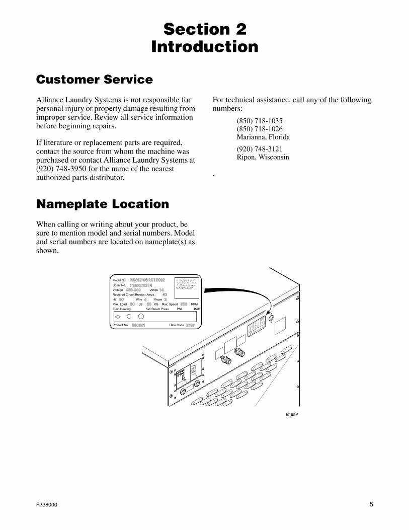
Nameplate LocationWhen calling or writing about your product, be sure to mention model and serial numbers. Model and serial numbers are located on nameplate(s) as shown.
UNIMAC
Model No.
HC80PC3AU10002
1195072314
208-240
1440
60
4
3
80
360797
560501
530
Serial No.
Voltage
Amps
Required Circuit Breaker A
mps.
Hz
Wire
Phase
Max. Load
KGMax. S
peed
RPM
LB
Elec. Heating
Product No.
Date CodeKW Steam Press
PSI
BAR
UNIMACModel No. HC80PC3AU100021195072314
208-240 1440
60 4 380 36
0797560501
530
Serial No.
Voltage Amps
Required Circuit Breaker Amps.
Hz Wire Phase
Max. Load KG Max. Speed RPMLB
Elec. Heating
Product No. Date Code
KW Steam Press PSI BAR
B155P
F238000 5
Section 2 Introduction
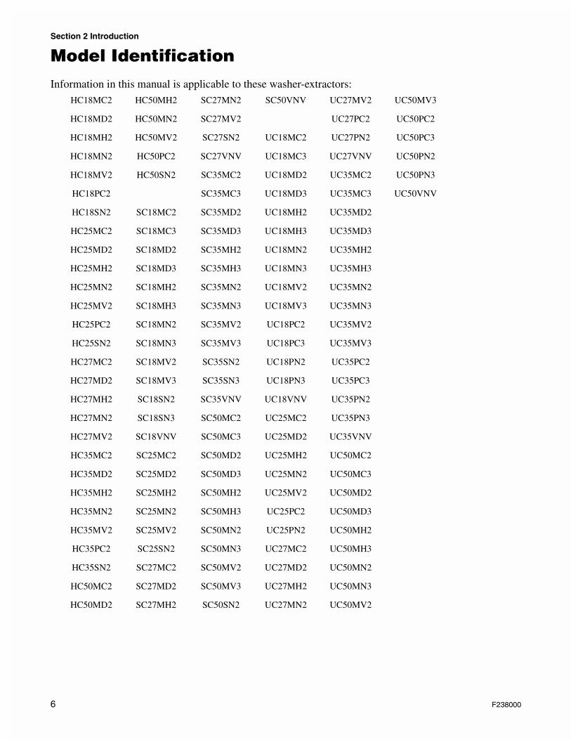
Model IdentificationInformation in this manual is applicable to these washer-extractors:
HC18MC2
HC18MD2
HC18MH2
HC18MN2
HC18MV2
HC18PC2
HC18SN2
HC25MC2
HC25MD2
HC25MH2
HC25MN2
HC25MV2
HC25PC2
HC25SN2
HC27MC2
HC27MD2
HC27MH2
HC27MN2
HC27MV2
HC35MC2
HC35MD2
HC35MH2
HC35MN2
HC35MV2
HC35PC2
HC35SN2
HC50MC2
HC50MD2
HC50MH2
HC50MN2
HC50MV2
HC50PC2
HC50SN2
SC18MC2
SC18MC3
SC18MD2
SC18MD3
SC18MH2
SC18MH3
SC18MN2
SC18MN3
SC18MV2
SC18MV3
SC18SN2
SC18SN3
SC18VNV
SC25MC2
SC25MD2
SC25MH2
SC25MN2
SC25MV2
SC25SN2
SC27MC2
SC27MD2
SC27MH2
SC27MN2
SC27MV2
SC27SN2
SC27VNV
SC35MC2
SC35MC3
SC35MD2
SC35MD3
SC35MH2
SC35MH3
SC35MN2
SC35MN3
SC35MV2
SC35MV3
SC35SN2
SC35SN3
SC35VNV
SC50MC2
SC50MC3
SC50MD2
SC50MD3
SC50MH2
SC50MH3
SC50MN2
SC50MN3
SC50MV2
SC50MV3
SC50SN2
SC50VNV
UC18MC2
UC18MC3
UC18MD2
UC18MD3
UC18MH2
UC18MH3
UC18MN2
UC18MN3
UC18MV2
UC18MV3
UC18PC2
UC18PC3
UC18PN2
UC18PN3
UC18VNV
UC25MC2
UC25MD2
UC25MH2
UC25MN2
UC25MV2
UC25PC2
UC25PN2
UC27MC2
UC27MD2
UC27MH2
UC27MN2
UC27MV2
UC27PC2
UC27PN2
UC27VNV
UC35MC2
UC35MC3
UC35MD2
UC35MD3
UC35MH2
UC35MH3
UC35MN2
UC35MN3
UC35MV2
UC35MV3
UC35PC2
UC35PC3
UC35PN2
UC35PN3
UC35VNV
UC50MC2
UC50MC3
UC50MD2
UC50MD3
UC50MH2
UC50MH3
UC50MN2
UC50MN3
UC50MV2
UC50MV3
UC50PC2
UC50PC3
UC50PN2
UC50PN3
UC50VNV
6 F238000
Section 2 Introduction
Model Familiarization
Model Number Familiarization Guide
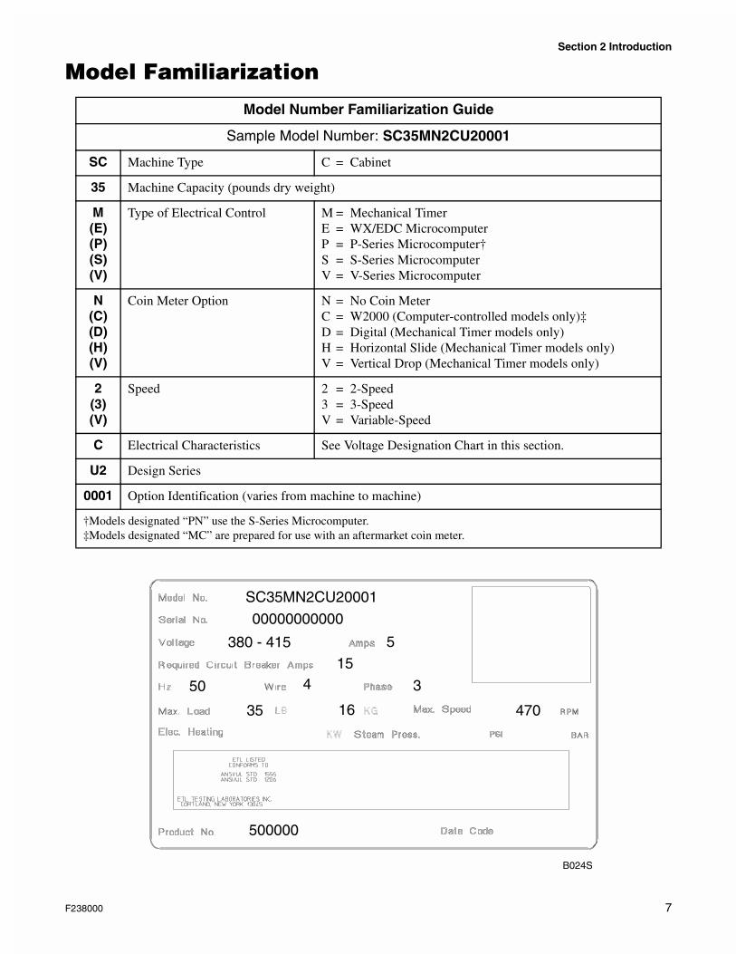
Sample Model Number: SC35MN2CU20001
SC Machine Type C = Cabinet
35 Machine Capacity (pounds dry weight)
M(E)(P)(S)(V)
Type of Electrical Control M = Mechanical TimerE = WX/EDC MicrocomputerP = P-Series Microcomputer†S = S-Series MicrocomputerV = V-Series Microcomputer
N(C)(D)(H)(V)
Coin Meter Option N = No Coin MeterC = W2000 (Computer-controlled models only)‡D = Digital (Mechanical Timer models only)H = Horizontal Slide (Mechanical Timer models only)V = Vertical Drop (Mechanical Timer models only)
2(3)(V)
Speed 2 = 2-Speed3 = 3-SpeedV = Variable-Speed
C Electrical Characteristics See Voltage Designation Chart in this section.
U2 Design Series
0001 Option Identification (varies from machine to machine)
†Models designated “PN” use the S-Series Microcomputer.‡Models designated “MC” are prepared for use with an aftermarket coin meter.
B024S
SC35MN2CU20001
380 - 415 515
00000000000
50 4 3
35 16 470
500000
F238000 7
Section 2 Introduction
How Your Washer-Extractor Works
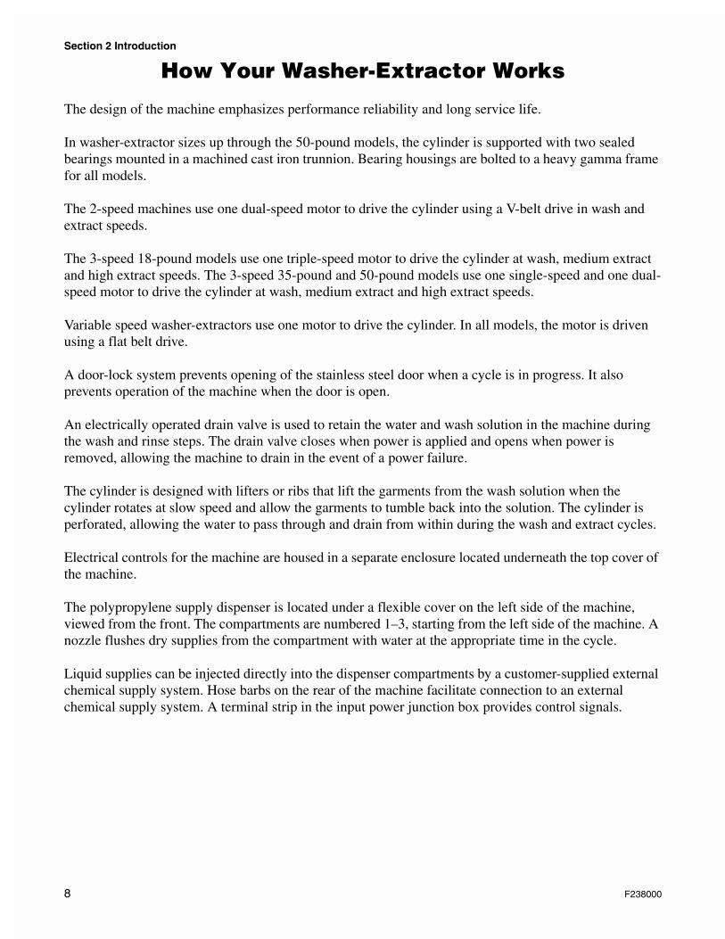
The design of the machine emphasizes performance reliability and long service life.
In washer-extractor sizes up through the 50-pound models, the cylinder is supported with two sealed bearings mounted in a machined cast iron trunnion. Bearing housings are bolted to a heavy gamma frame for all models.
The 2-speed machines use one dual-speed motor to drive the cylinder using a V-belt drive in wash and extract speeds.
The 3-speed 18-pound models use one triple-speed motor to drive the cylinder at wash, medium extract and high extract speeds. The 3-speed 35-pound and 50-pound models use one single-speed and one dual-speed motor to drive the cylinder at wash, medium extract and high extract speeds.
Variable speed washer-extractors use one motor to drive the cylinder. In all models, the motor is driven using a flat belt drive.
A door-lock system prevents opening of the stainless steel door when a cycle is in progress. It also prevents operation of the machine when the door is open.
An electrically operated drain valve is used to retain the water and wash solution in the machine during the wash and rinse steps. The drain valve closes when power is applied and opens when power is removed, allowing the machine to drain in the event of a power failure.
The cylinder is designed with lifters or ribs that lift the garments from the wash solution when the cylinder rotates at slow speed and allow the garments to tumble back into the solution. The cylinder is perforated, allowing the water to pass through and drain from within during the wash and extract cycles.
Electrical controls for the machine are housed in a separate enclosure located underneath the top cover of the machine.
The polypropylene supply dispenser is located under a flexible cover on the left side of the machine, viewed from the front. The compartments are numbered 1–3, starting from the left side of the machine. A nozzle flushes dry supplies from the compartment with water at the appropriate time in the cycle.
Liquid supplies can be injected directly into the dispenser compartments by a customer-supplied external chemical supply system. Hose barbs on the rear of the machine facilitate connection to an external chemical supply system. A terminal strip in the input power junction box provides control signals.
8 F238000
Section 3Troubleshooting
To reduce the risk of electrical shock, fire, explosion, serious injury or death:• Disconnect electric power to the washer-extractor before servicing.• Never start the washer-extractor with any guards/panels removed.• Whenever ground wires are removed during servicing, these ground wires must be
reconnected to ensure that the washer-extractor is properly grounded.W171
WARNING
IMPORTANT: Refer to appropriate model wiring diagram for aid in testing components.
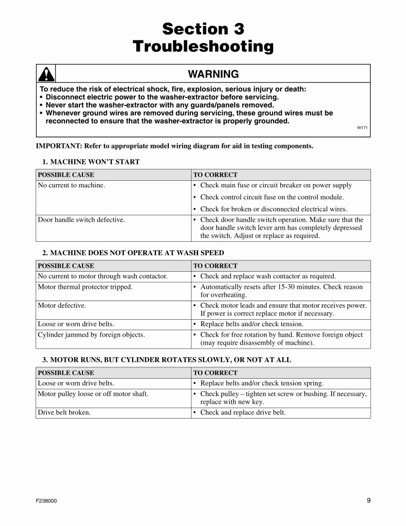
1. MACHINE WON’T START
2. MACHINE DOES NOT OPERATE AT WASH SPEED
3. MOTOR RUNS, BUT CYLINDER ROTATES SLOWLY, OR NOT AT ALL
POSSIBLE CAUSE TO CORRECT
No current to machine. • Check main fuse or circuit breaker on power supply
• Check control circuit fuse on the control module.
• Check for broken or disconnected electrical wires.
Door handle switch defective. • Check door handle switch operation. Make sure that the door handle switch lever arm has completely depressed the switch. Adjust or replace as required.
POSSIBLE CAUSE TO CORRECT
No current to motor through wash contactor. • Check and replace wash contactor as required.
Motor thermal protector tripped. • Automatically resets after 15-30 minutes. Check reason for overheating.
Motor defective. • Check motor leads and ensure that motor receives power. If power is correct replace motor if necessary.
Loose or worn drive belts. • Replace belts and/or check tension.
Cylinder jammed by foreign objects. • Check for free rotation by hand. Remove foreign object (may require disassembly of machine).
POSSIBLE CAUSE TO CORRECT
Loose or worn drive belts. • Replace belts and/or check tension spring.
Motor pulley loose or off motor shaft. • Check pulley – tighten set screw or bushing. If necessary, replace with new key.
Drive belt broken. • Check and replace drive belt.
F238000 9
Section 3 Troubleshooting
To reduce the risk of electrical shock, fire, explosion, serious injury or death:• Disconnect electric power to the washer-extractor before servicing.• Never start the washer-extractor with any guards/panels removed.• Whenever ground wires are removed during servicing, these ground wires must be
reconnected to ensure that the washer-extractor is properly grounded.W171
WARNING
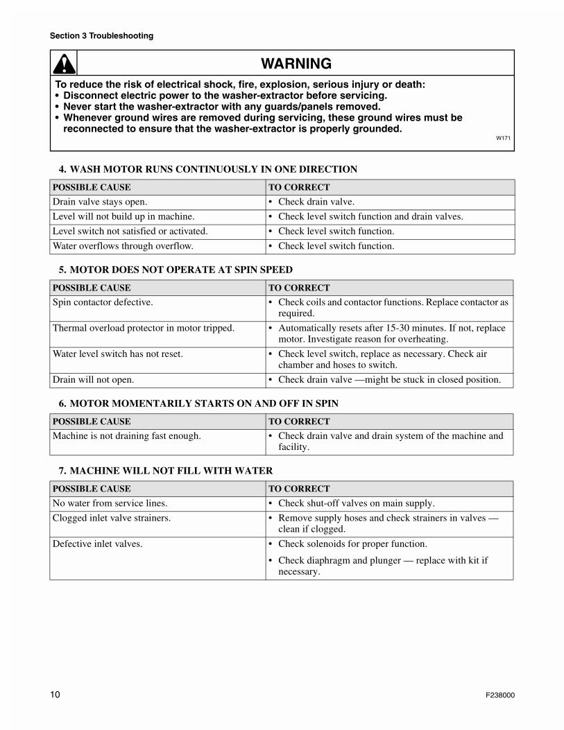
4. WASH MOTOR RUNS CONTINUOUSLY IN ONE DIRECTION
5. MOTOR DOES NOT OPERATE AT SPIN SPEED
6. MOTOR MOMENTARILY STARTS ON AND OFF IN SPIN
7. MACHINE WILL NOT FILL WITH WATER
POSSIBLE CAUSE TO CORRECT
Drain valve stays open. • Check drain valve.
Level will not build up in machine. • Check level switch function and drain valves.
Level switch not satisfied or activated. • Check level switch function.
Water overflows through overflow. • Check level switch function.
POSSIBLE CAUSE TO CORRECT
Spin contactor defective. • Check coils and contactor functions. Replace contactor as required.
Thermal overload protector in motor tripped. • Automatically resets after 15-30 minutes. If not, replace motor. Investigate reason for overheating.
Water level switch has not reset. • Check level switch, replace as necessary. Check air chamber and hoses to switch.
Drain will not open. • Check drain valve —might be stuck in closed position.
POSSIBLE CAUSE TO CORRECT
Machine is not draining fast enough. • Check drain valve and drain system of the machine and facility.
POSSIBLE CAUSE TO CORRECT
No water from service lines. • Check shut-off valves on main supply.
Clogged inlet valve strainers. • Remove supply hoses and check strainers in valves —clean if clogged.
Defective inlet valves. • Check solenoids for proper function.
• Check diaphragm and plunger — replace with kit if necessary.
10 F238000
Section 3 Troubleshooting
To reduce the risk of electrical shock, fire, explosion, serious injury or death:• Disconnect electric power to the washer-extractor before servicing.• Never start the washer-extractor with any guards/panels removed.• Whenever ground wires are removed during servicing, these ground wires must be
reconnected to ensure that the washer-extractor is properly grounded.W171
WARNING
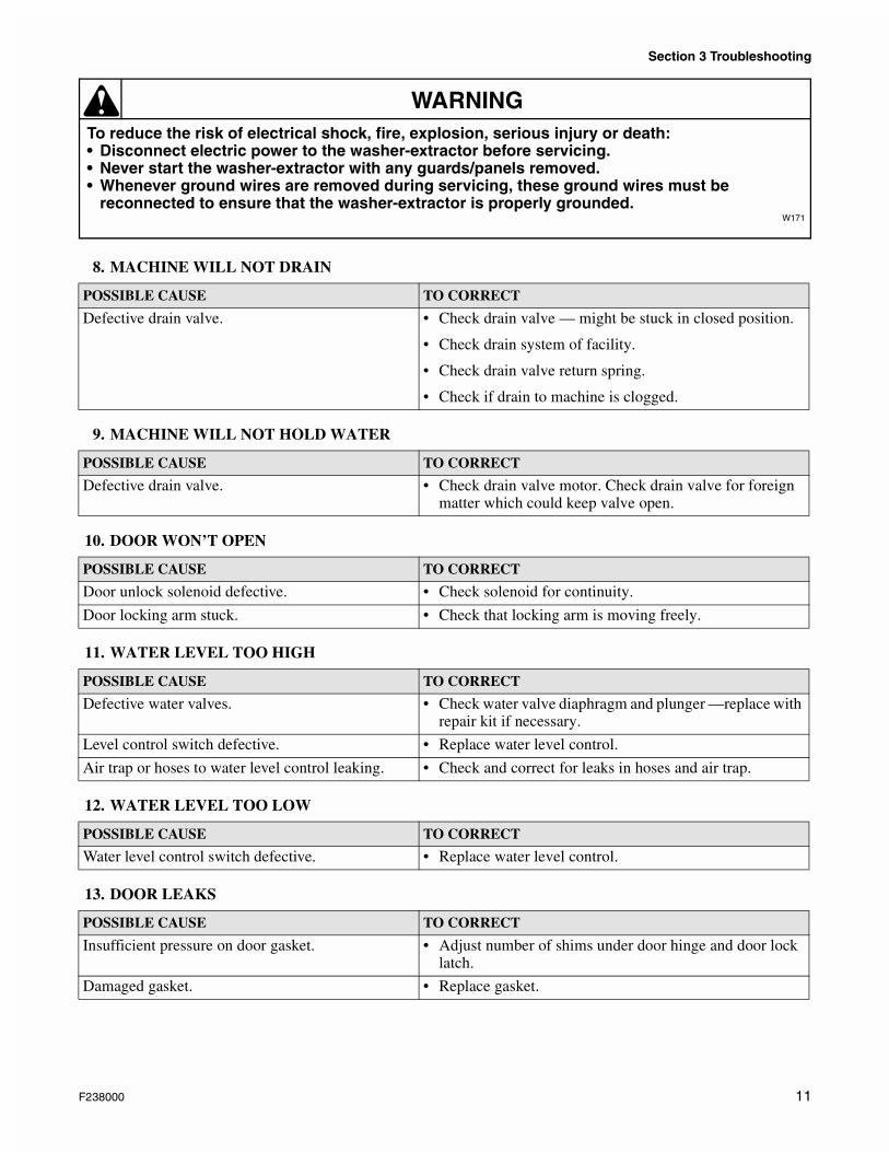
8. MACHINE WILL NOT DRAIN
9. MACHINE WILL NOT HOLD WATER
10. DOOR WON’T OPEN
11. WATER LEVEL TOO HIGH
12. WATER LEVEL TOO LOW
13. DOOR LEAKS
POSSIBLE CAUSE TO CORRECT
Defective drain valve. • Check drain valve — might be stuck in closed position.
• Check drain system of facility.
• Check drain valve return spring.
• Check if drain to machine is clogged.
POSSIBLE CAUSE TO CORRECT
Defective drain valve. • Check drain valve motor. Check drain valve for foreign matter which could keep valve open.
POSSIBLE CAUSE TO CORRECT
Door unlock solenoid defective. • Check solenoid for continuity.
Door locking arm stuck. • Check that locking arm is moving freely.
POSSIBLE CAUSE TO CORRECT
Defective water valves. • Check water valve diaphragm and plunger —replace with repair kit if necessary.
Level control switch defective. • Replace water level control.
Air trap or hoses to water level control leaking. • Check and correct for leaks in hoses and air trap.
POSSIBLE CAUSE TO CORRECT
Water level control switch defective. • Replace water level control.
POSSIBLE CAUSE TO CORRECT
Insufficient pressure on door gasket. • Adjust number of shims under door hinge and door lock latch.
Damaged gasket. • Replace gasket.
F238000 11
Section 3 Troubleshooting
To reduce the risk of electrical shock, fire, explosion, serious injury or death:• Disconnect electric power to the washer-extractor before servicing.• Never start the washer-extractor with any guards/panels removed.• Whenever ground wires are removed during servicing, these ground wires must be
reconnected to ensure that the washer-extractor is properly grounded.W171
WARNING
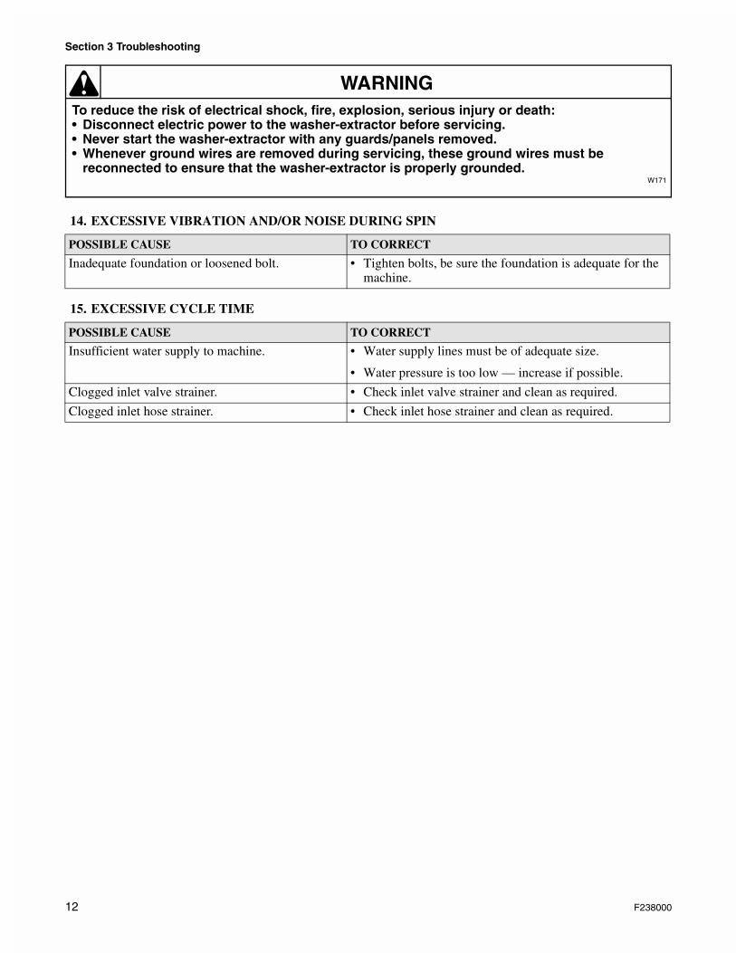
14. EXCESSIVE VIBRATION AND/OR NOISE DURING SPIN
15. EXCESSIVE CYCLE TIME
POSSIBLE CAUSE TO CORRECT
Inadequate foundation or loosened bolt. • Tighten bolts, be sure the foundation is adequate for the machine.
POSSIBLE CAUSE TO CORRECT
Insufficient water supply to machine. • Water supply lines must be of adequate size.
• Water pressure is too low — increase if possible.
Clogged inlet valve strainer. • Check inlet valve strainer and clean as required.
Clogged inlet hose strainer. • Check inlet hose strainer and clean as required.
12 F238000
Section 4Service Procedures
To reduce the risk of electrical shock, fire, explosion, serious injury or death:• Disconnect electric power to the washer-extractor before servicing.• Never start the washer-extractor with any guards/panels removed.• Whenever ground wires are removed during servicing, these ground wires must be
reconnected to ensure that the washer-extractor is properly grounded.W171
WARNING
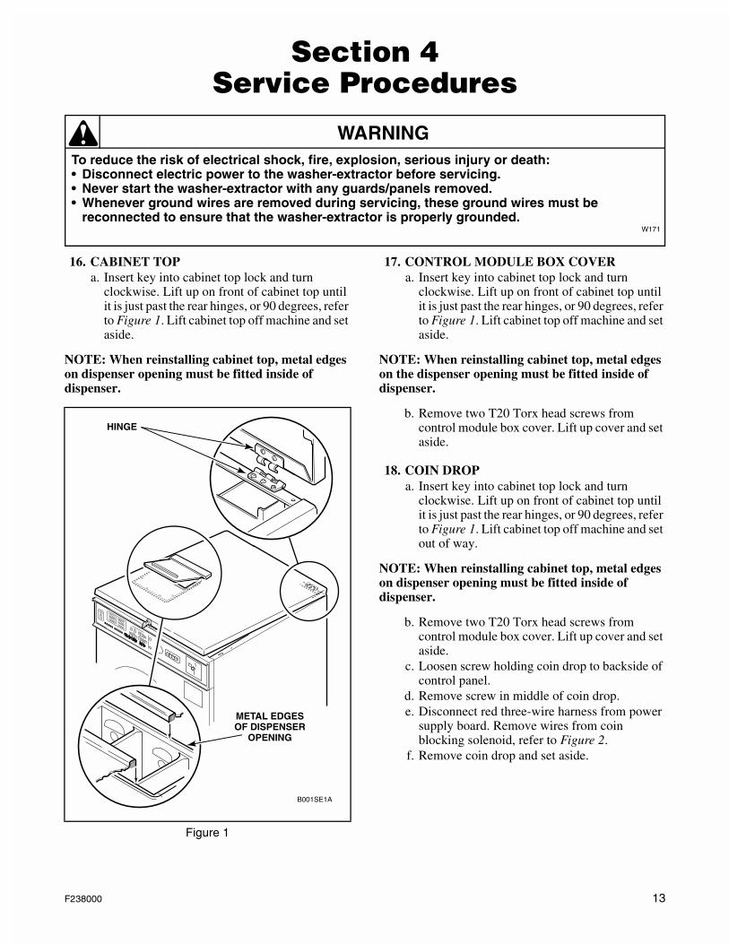
16. CABINET TOPa. Insert key into cabinet top lock and turn
clockwise. Lift up on front of cabinet top until it is just past the rear hinges, or 90 degrees, refer to Figure 1. Lift cabinet top off machine and set aside.
NOTE: When reinstalling cabinet top, metal edges on dispenser opening must be fitted inside of dispenser.
17. CONTROL MODULE BOX COVERa. Insert key into cabinet top lock and turn
clockwise. Lift up on front of cabinet top until it is just past the rear hinges, or 90 degrees, refer to Figure 1. Lift cabinet top off machine and set aside.
NOTE: When reinstalling cabinet top, metal edges on the dispenser opening must be fitted inside of dispenser.
b. Remove two T20 Torx head screws from control module box cover. Lift up cover and set aside.
18. COIN DROPa. Insert key into cabinet top lock and turn
clockwise. Lift up on front of cabinet top until it is just past the rear hinges, or 90 degrees, refer to Figure 1. Lift cabinet top off machine and set out of way.
NOTE: When reinstalling cabinet top, metal edges on dispenser opening must be fitted inside of dispenser.
b. Remove two T20 Torx head screws from control module box cover. Lift up cover and set aside.
c. Loosen screw holding coin drop to backside of control panel.
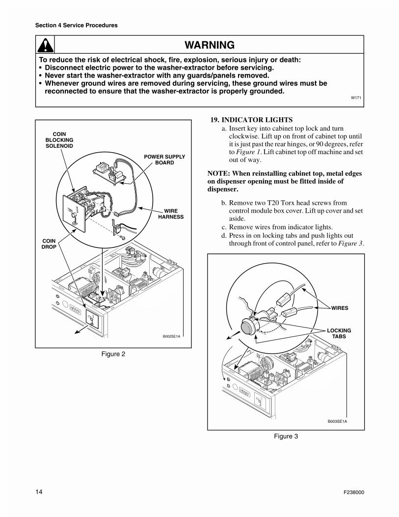
d. Remove screw in middle of coin drop.e. Disconnect red three-wire harness from power
supply board. Remove wires from coin blocking solenoid, refer to Figure 2.
f. Remove coin drop and set aside.
Figure 1
B001SE1A
METAL EDGESOF DISPENSER
OPENING
HINGE
F238000 13
Section 4 Service Procedures
To reduce the risk of electrical shock, fire, explosion, serious injury or death:• Disconnect electric power to the washer-extractor before servicing.• Never start the washer-extractor with any guards/panels removed.• Whenever ground wires are removed during servicing, these ground wires must be
reconnected to ensure that the washer-extractor is properly grounded.W171
WARNING
19. INDICATOR LIGHTSa. Insert key into cabinet top lock and turn
clockwise. Lift up on front of cabinet top until it is just past the rear hinges, or 90 degrees, refer to Figure 1. Lift cabinet top off machine and set out of way.
NOTE: When reinstalling cabinet top, metal edges on dispenser opening must be fitted inside of dispenser.
b. Remove two T20 Torx head screws from control module box cover. Lift up cover and set aside.
c. Remove wires from indicator lights.d. Press in on locking tabs and push lights out
through front of control panel, refer to Figure 3.
Figure 2
B002SE1A
POWER SUPPLYBOARD
WIREHARNESS
COINDROP
COINBLOCKINGSOLENOID
Figure 3
B003SE1A
WIRES
LOCKINGTABS
14 F238000
Section 4 Service Procedures
To reduce the risk of electrical shock, fire, explosion, serious injury or death:• Disconnect electric power to the washer-extractor before servicing.• Never start the washer-extractor with any guards/panels removed.• Whenever ground wires are removed during servicing, these ground wires must be
reconnected to ensure that the washer-extractor is properly grounded.W171
WARNING
20. GRAPHIC PANEL OVERLAY
NOTE: The graphic panel overlay has an adhesive backing. Using a hair dryer to heat up adhesive will make it easier to pull off overlay.
a. Remove adhesive overlay by peeling it from front channel.
Installing Graphic Panel Overlay
IMPORTANT: Use denatured alcohol to clean residue from front channel before applying new decal.
NOTE: Before removing protective backing from new overlay, check fit of overlay to front channel. Indicator light holes and selector switch holes are the locating guides.
a. Once panel overlay is fitted to front channel, carefully peel protective backing from right end of panel overlay and press in place.
b. Remove rest of the protective backing from panel overlay and press overlay into place.
21. TIMER AND SELECTOR SWITCH BRACKETa. Insert key into cabinet top lock and turn
clockwise. Lift up on front of cabinet top until it is just past the rear hinges, or 90 degrees, refer to Figure 1. Lift cabinet top off machine and set out of way.
NOTE: When reinstalling cabinet top, metal edges on dispenser opening must be fitted inside of dispenser.
b. Remove two T20 Torx head screws from control module box cover. Lift up cover and set aside.
IMPORTANT: When replacing the timer and selector switch assembly, do a wire-for-wire exchange, or write down all the wire terminal connections before removing any wires. If you have a problem, refer to the wiring diagram on the underside of the cabinet top.
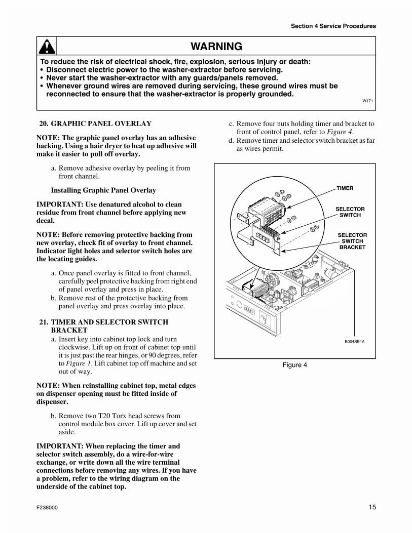
c. Remove four nuts holding timer and bracket to front of control panel, refer to Figure 4.
d. Remove timer and selector switch bracket as far as wires permit.
Figure 4
B004SE1A
SELECTORSWITCH
BRACKET
SELECTORSWITCH
TIMER
F238000 15
Section 4 Service Procedures
To reduce the risk of electrical shock, fire, explosion, serious injury or death:• Disconnect electric power to the washer-extractor before servicing.• Never start the washer-extractor with any guards/panels removed.• Whenever ground wires are removed during servicing, these ground wires must be
reconnected to ensure that the washer-extractor is properly grounded.W171
WARNING
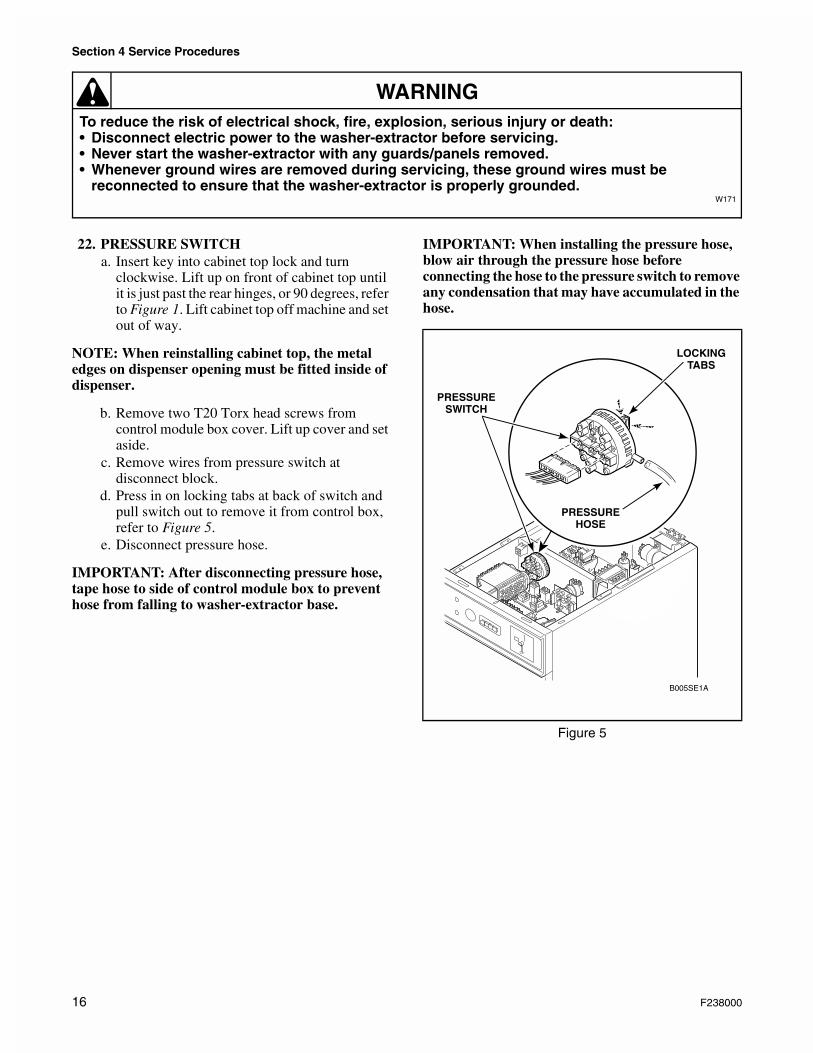
22. PRESSURE SWITCHa. Insert key into cabinet top lock and turn
clockwise. Lift up on front of cabinet top until it is just past the rear hinges, or 90 degrees, refer to Figure 1. Lift cabinet top off machine and set out of way.
NOTE: When reinstalling cabinet top, the metal edges on dispenser opening must be fitted inside of dispenser.
b. Remove two T20 Torx head screws from control module box cover. Lift up cover and set aside.
c. Remove wires from pressure switch at disconnect block.
d. Press in on locking tabs at back of switch and pull switch out to remove it from control box, refer to Figure 5.
e. Disconnect pressure hose.
IMPORTANT: After disconnecting pressure hose, tape hose to side of control module box to prevent hose from falling to washer-extractor base.
IMPORTANT: When installing the pressure hose, blow air through the pressure hose before connecting the hose to the pressure switch to remove any condensation that may have accumulated in the hose.
Figure 5
B005SE1A
LOCKINGTABS
PRESSUREHOSE
PRESSURESWITCH
16 F238000
Section 4 Service Procedures
To reduce the risk of electrical shock, fire, explosion, serious injury or death:• Disconnect electric power to the washer-extractor before servicing.• Never start the washer-extractor with any guards/panels removed.• Whenever ground wires are removed during servicing, these ground wires must be
reconnected to ensure that the washer-extractor is properly grounded.W171
WARNING
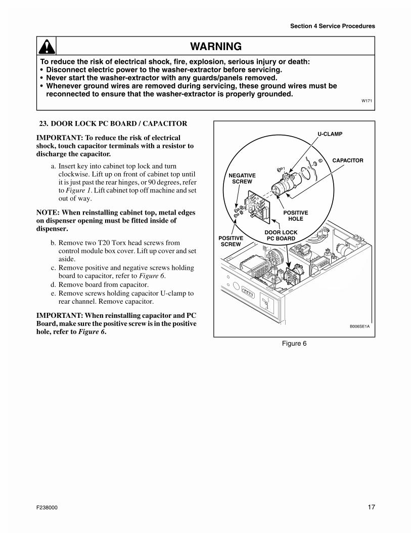
23. DOOR LOCK PC BOARD / CAPACITOR
IMPORTANT: To reduce the risk of electrical shock, touch capacitor terminals with a resistor to discharge the capacitor.
a. Insert key into cabinet top lock and turn clockwise. Lift up on front of cabinet top until it is just past the rear hinges, or 90 degrees, refer to Figure 1. Lift cabinet top off machine and set out of way.
NOTE: When reinstalling cabinet top, metal edges on dispenser opening must be fitted inside of dispenser.
b. Remove two T20 Torx head screws from control module box cover. Lift up cover and set aside.
c. Remove positive and negative screws holding board to capacitor, refer to Figure 6.
d. Remove board from capacitor.e. Remove screws holding capacitor U-clamp to
rear channel. Remove capacitor.
IMPORTANT: When reinstalling capacitor and PC Board, make sure the positive screw is in the positive hole, refer to Figure 6.
Figure 6
+
B006SE1A
CAPACITOR
U-CLAMP
NEGATIVESCREW
POSITIVESCREW
DOOR LOCKPC BOARD
POSITIVEHOLE
F238000 17
Section 4 Service Procedures
To reduce the risk of electrical shock, fire, explosion, serious injury or death:• Disconnect electric power to the washer-extractor before servicing.• Never start the washer-extractor with any guards/panels removed.• Whenever ground wires are removed during servicing, these ground wires must be
reconnected to ensure that the washer-extractor is properly grounded.W171
WARNING
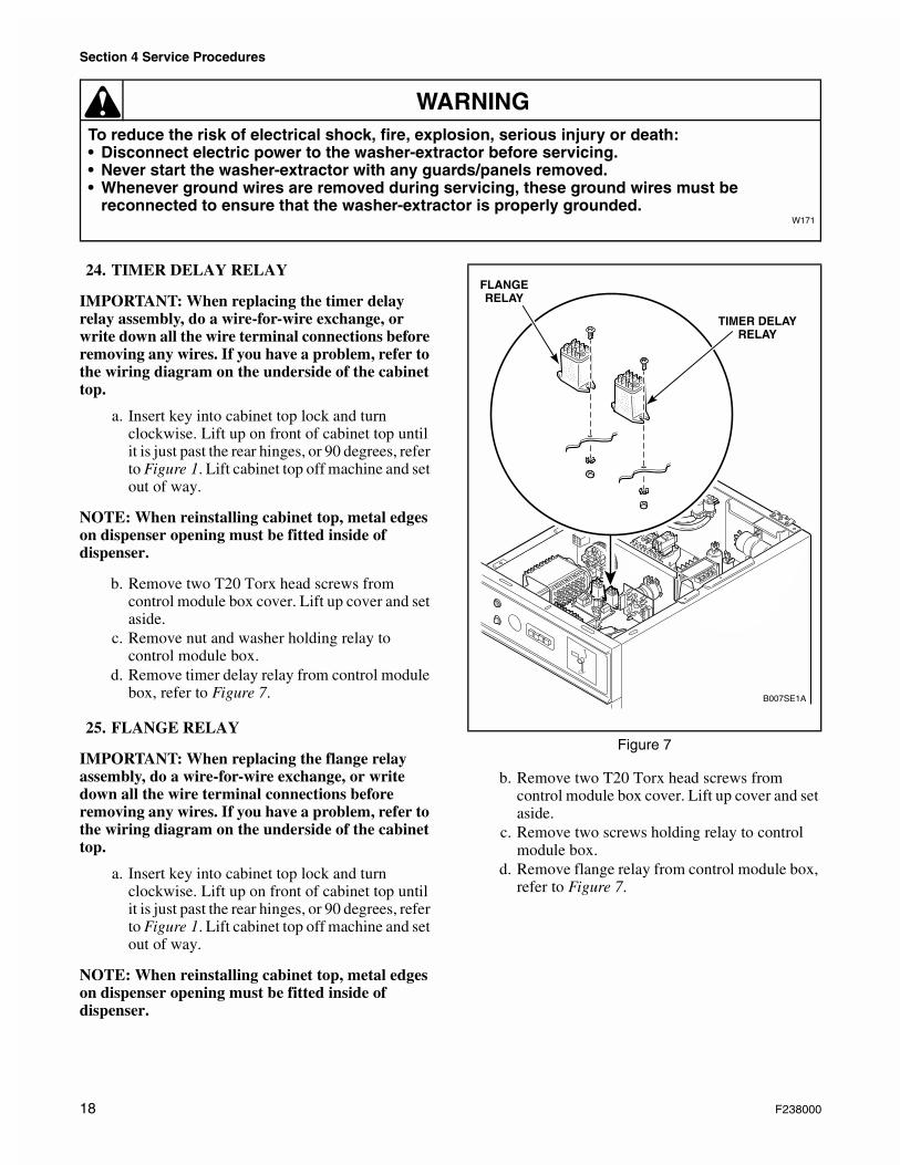
24. TIMER DELAY RELAY
IMPORTANT: When replacing the timer delay relay assembly, do a wire-for-wire exchange, or write down all the wire terminal connections before removing any wires. If you have a problem, refer to the wiring diagram on the underside of the cabinet top.
a. Insert key into cabinet top lock and turn clockwise. Lift up on front of cabinet top until it is just past the rear hinges, or 90 degrees, refer to Figure 1. Lift cabinet top off machine and set out of way.
NOTE: When reinstalling cabinet top, metal edges on dispenser opening must be fitted inside of dispenser.
b. Remove two T20 Torx head screws from control module box cover. Lift up cover and set aside.
c. Remove nut and washer holding relay to control module box.
d. Remove timer delay relay from control module box, refer to Figure 7.
25. FLANGE RELAY
IMPORTANT: When replacing the flange relay assembly, do a wire-for-wire exchange, or write down all the wire terminal connections before removing any wires. If you have a problem, refer to the wiring diagram on the underside of the cabinet top.
a. Insert key into cabinet top lock and turn clockwise. Lift up on front of cabinet top until it is just past the rear hinges, or 90 degrees, refer to Figure 1. Lift cabinet top off machine and set out of way.
NOTE: When reinstalling cabinet top, metal edges on dispenser opening must be fitted inside of dispenser.
b. Remove two T20 Torx head screws from control module box cover. Lift up cover and set aside.
c. Remove two screws holding relay to control module box.
d. Remove flange relay from control module box, refer to Figure 7.
Figure 7
B007SE1A
TIMER DELAYRELAY
FLANGERELAY
18 F238000
Section 4 Service Procedures
To reduce the risk of electrical shock, fire, explosion, serious injury or death:• Disconnect electric power to the washer-extractor before servicing.• Never start the washer-extractor with any guards/panels removed.• Whenever ground wires are removed during servicing, these ground wires must be
reconnected to ensure that the washer-extractor is properly grounded.W171
WARNING
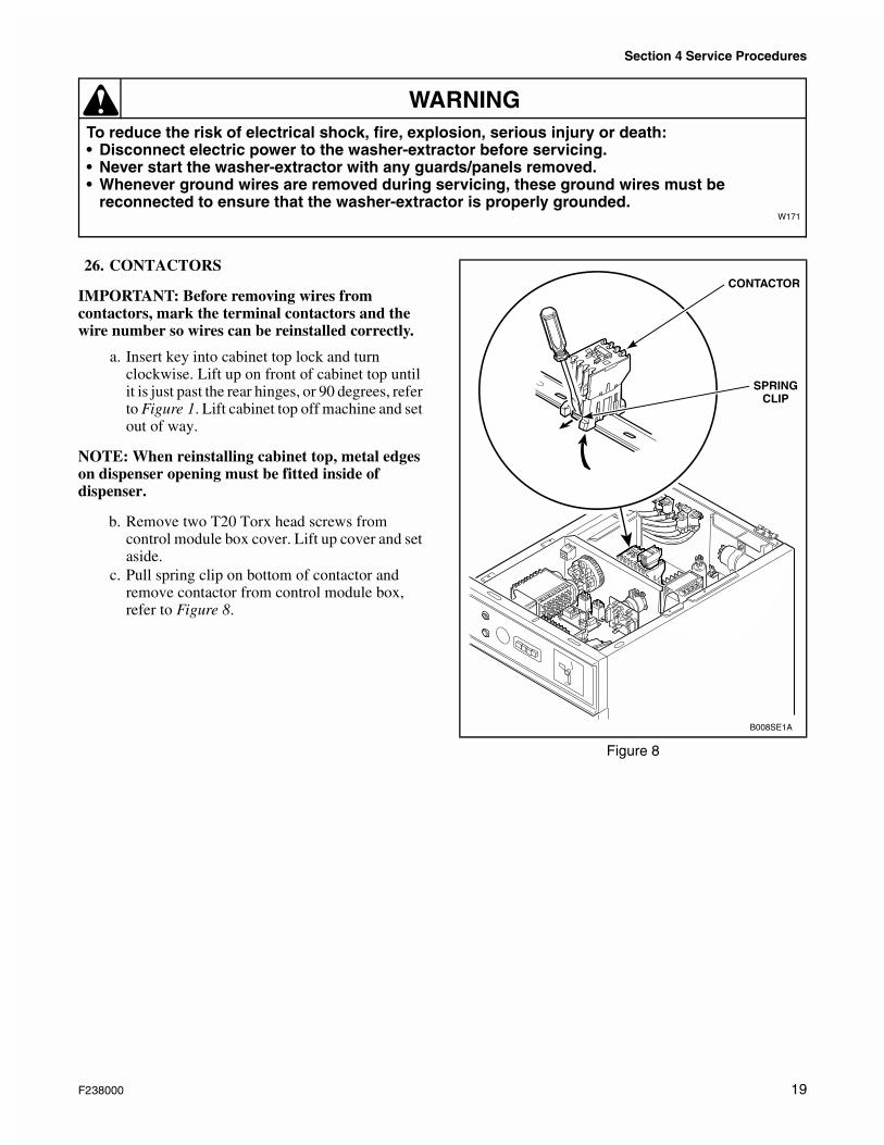
26. CONTACTORS
IMPORTANT: Before removing wires from contactors, mark the terminal contactors and the wire number so wires can be reinstalled correctly.
a. Insert key into cabinet top lock and turn clockwise. Lift up on front of cabinet top until it is just past the rear hinges, or 90 degrees, refer to Figure 1. Lift cabinet top off machine and set out of way.
NOTE: When reinstalling cabinet top, metal edges on dispenser opening must be fitted inside of dispenser.
b. Remove two T20 Torx head screws from control module box cover. Lift up cover and set aside.
c. Pull spring clip on bottom of contactor and remove contactor from control module box, refer to Figure 8.
Figure 8
B008SE1A
SPRINGCLIP
CONTACTOR
F238000 19
Section 4 Service Procedures
To reduce the risk of electrical shock, fire, explosion, serious injury or death:• Disconnect electric power to the washer-extractor before servicing.• Never start the washer-extractor with any guards/panels removed.• Whenever ground wires are removed during servicing, these ground wires must be
reconnected to ensure that the washer-extractor is properly grounded.W171
WARNING
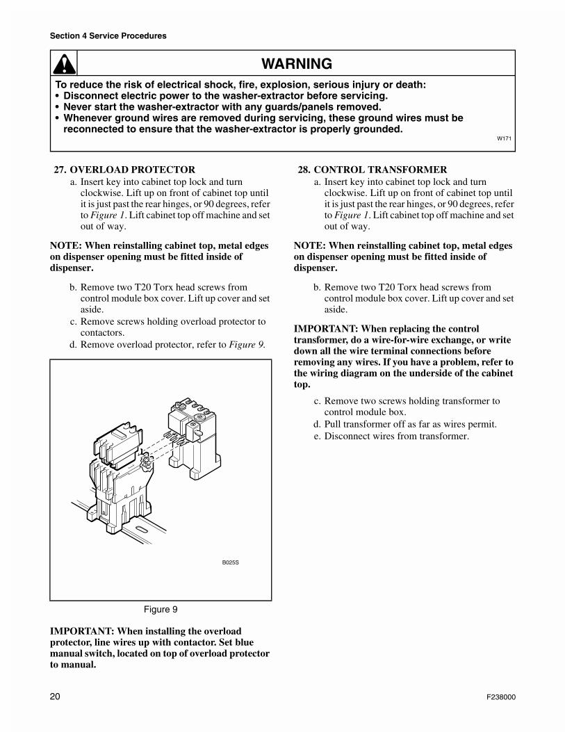
27. OVERLOAD PROTECTORa. Insert key into cabinet top lock and turn
clockwise. Lift up on front of cabinet top until it is just past the rear hinges, or 90 degrees, refer to Figure 1. Lift cabinet top off machine and set out of way.
NOTE: When reinstalling cabinet top, metal edges on dispenser opening must be fitted inside of dispenser.
b. Remove two T20 Torx head screws from control module box cover. Lift up cover and set aside.
c. Remove screws holding overload protector to contactors.
d. Remove overload protector, refer to Figure 9.
IMPORTANT: When installing the overload protector, line wires up with contactor. Set blue manual switch, located on top of overload protector to manual.
28. CONTROL TRANSFORMERa. Insert key into cabinet top lock and turn
clockwise. Lift up on front of cabinet top until it is just past the rear hinges, or 90 degrees, refer to Figure 1. Lift cabinet top off machine and set out of way.
NOTE: When reinstalling cabinet top, metal edges on dispenser opening must be fitted inside of dispenser.
b. Remove two T20 Torx head screws from control module box cover. Lift up cover and set aside.
IMPORTANT: When replacing the control transformer, do a wire-for-wire exchange, or write down all the wire terminal connections before removing any wires. If you have a problem, refer to the wiring diagram on the underside of the cabinet top.
c. Remove two screws holding transformer to control module box.
d. Pull transformer off as far as wires permit.e. Disconnect wires from transformer.
Figure 9
B025S
20 F238000
Section 4 Service Procedures
To reduce the risk of electrical shock, fire, explosion, serious injury or death:• Disconnect electric power to the washer-extractor before servicing.• Never start the washer-extractor with any guards/panels removed.• Whenever ground wires are removed during servicing, these ground wires must be
reconnected to ensure that the washer-extractor is properly grounded.W171
WARNING
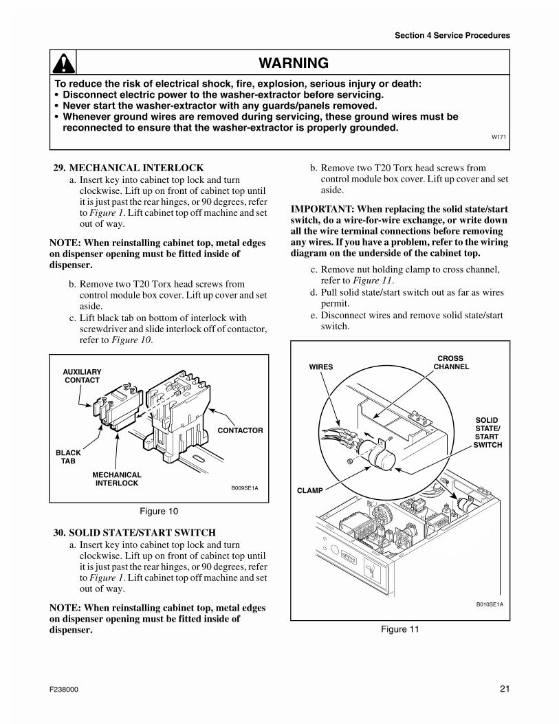
29. MECHANICAL INTERLOCKa. Insert key into cabinet top lock and turn
clockwise. Lift up on front of cabinet top until it is just past the rear hinges, or 90 degrees, refer to Figure 1. Lift cabinet top off machine and set out of way.
NOTE: When reinstalling cabinet top, metal edges on dispenser opening must be fitted inside of dispenser.
b. Remove two T20 Torx head screws from control module box cover. Lift up cover and set aside.
c. Lift black tab on bottom of interlock with screwdriver and slide interlock off of contactor, refer to Figure 10.
30. SOLID STATE/START SWITCHa. Insert key into cabinet top lock and turn
clockwise. Lift up on front of cabinet top until it is just past the rear hinges, or 90 degrees, refer to Figure 1. Lift cabinet top off machine and set out of way.
NOTE: When reinstalling cabinet top, metal edges on dispenser opening must be fitted inside of dispenser.
b. Remove two T20 Torx head screws from control module box cover. Lift up cover and set aside.
IMPORTANT: When replacing the solid state/start switch, do a wire-for-wire exchange, or write down all the wire terminal connections before removing any wires. If you have a problem, refer to the wiring diagram on the underside of the cabinet top.
c. Remove nut holding clamp to cross channel, refer to Figure 11.
d. Pull solid state/start switch out as far as wires permit.
e. Disconnect wires and remove solid state/start switch.
Figure 10
B009SE1A
CONTACTOR
AUXILIARYCONTACT
MECHANICALINTERLOCK
BLACKTAB
Figure 11
B010SE1A
SOLID STATE/START SWITCH
CROSS CHANNELWIRES
CLAMP
F238000 21
Section 4 Service Procedures
To reduce the risk of electrical shock, fire, explosion, serious injury or death:• Disconnect electric power to the washer-extractor before servicing.• Never start the washer-extractor with any guards/panels removed.• Whenever ground wires are removed during servicing, these ground wires must be
reconnected to ensure that the washer-extractor is properly grounded.W171
WARNING
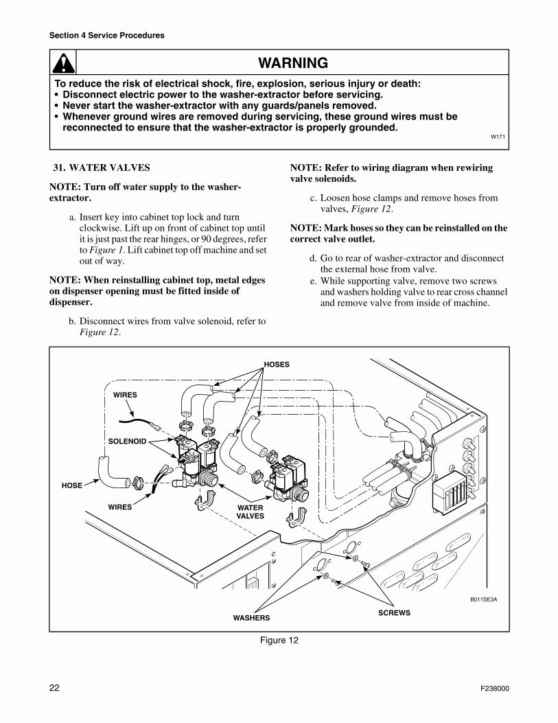
31. WATER VALVES
NOTE: Turn off water supply to the washer-extractor.
a. Insert key into cabinet top lock and turn clockwise. Lift up on front of cabinet top until it is just past the rear hinges, or 90 degrees, refer to Figure 1. Lift cabinet top off machine and set out of way.
NOTE: When reinstalling cabinet top, metal edges on dispenser opening must be fitted inside of dispenser.
b. Disconnect wires from valve solenoid, refer to Figure 12.
NOTE: Refer to wiring diagram when rewiring valve solenoids.
c. Loosen hose clamps and remove hoses from valves, Figure 12.
NOTE: Mark hoses so they can be reinstalled on the correct valve outlet.
d. Go to rear of washer-extractor and disconnect the external hose from valve.
e. While supporting valve, remove two screws and washers holding valve to rear cross channel and remove valve from inside of machine.
Figure 12
B011SE3A
SCREWS
WIRES
WIRES
HOSE
WATERVALVES
HOSES
WASHERS
SOLENOID
22 F238000
Section 4 Service Procedures
To reduce the risk of electrical shock, fire, explosion, serious injury or death:• Disconnect electric power to the washer-extractor before servicing.• Never start the washer-extractor with any guards/panels removed.• Whenever ground wires are removed during servicing, these ground wires must be
reconnected to ensure that the washer-extractor is properly grounded.W171
WARNING
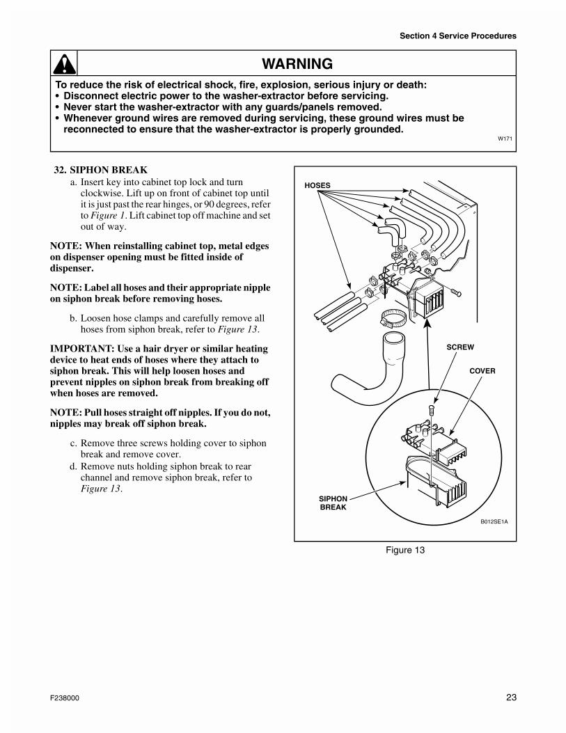
32. SIPHON BREAKa. Insert key into cabinet top lock and turn
clockwise. Lift up on front of cabinet top until it is just past the rear hinges, or 90 degrees, refer to Figure 1. Lift cabinet top off machine and set out of way.
NOTE: When reinstalling cabinet top, metal edges on dispenser opening must be fitted inside of dispenser.
NOTE: Label all hoses and their appropriate nipple on siphon break before removing hoses.
b. Loosen hose clamps and carefully remove all hoses from siphon break, refer to Figure 13.
IMPORTANT: Use a hair dryer or similar heating device to heat ends of hoses where they attach to siphon break. This will help loosen hoses and prevent nipples on siphon break from breaking off when hoses are removed.
NOTE: Pull hoses straight off nipples. If you do not, nipples may break off siphon break.
c. Remove three screws holding cover to siphon break and remove cover.
d. Remove nuts holding siphon break to rear channel and remove siphon break, refer to Figure 13.
Figure 13
B012SE1A
SIPHONBREAK
COVER
HOSES
SCREW
F238000 23
Section 4 Service Procedures
To reduce the risk of electrical shock, fire, explosion, serious injury or death:• Disconnect electric power to the washer-extractor before servicing.• Never start the washer-extractor with any guards/panels removed.• Whenever ground wires are removed during servicing, these ground wires must be
reconnected to ensure that the washer-extractor is properly grounded.W171
WARNING
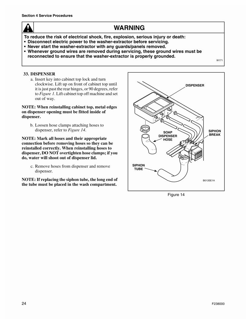
33. DISPENSERa. Insert key into cabinet top lock and turn
clockwise. Lift up on front of cabinet top until it is just past the rear hinges, or 90 degrees, refer to Figure 1. Lift cabinet top off machine and set out of way.
NOTE: When reinstalling cabinet top, metal edges on dispenser opening must be fitted inside of dispenser.
b. Loosen hose clamps attaching hoses to dispenser, refer to Figure 14.
NOTE: Mark all hoses and their appropriate connection before removing hoses so they can be reinstalled correctly. When reinstalling hoses to dispenser, DO NOT overtighten hose clamps; if you do, water will shoot out of dispenser lid.
c. Remove hoses from dispenser and remove dispenser.
NOTE: If replacing the siphon tube, the long end of the tube must be placed in the wash compartment.
Figure 14
B013SE1A
SIPHONTUBE
SIPHONBREAK
DISPENSER
SOAPDISPENSER
HOSE
24 F238000
Section 4 Service Procedures
To reduce the risk of electrical shock, fire, explosion, serious injury or death:• Disconnect electric power to the washer-extractor before servicing.• Never start the washer-extractor with any guards/panels removed.• Whenever ground wires are removed during servicing, these ground wires must be
reconnected to ensure that the washer-extractor is properly grounded.W171
WARNING
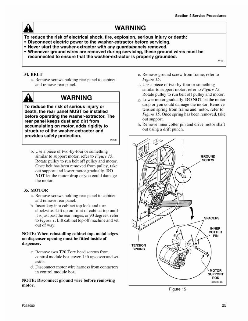
34. BELTa. Remove screws holding rear panel to cabinet
and remove rear panel.
b. Use a piece of two-by-four or something similar to support motor, refer to Figure 15. Rotate pulley to run belt off pulley and motor. Once belt has been removed from pulley, take out support and lower motor gradually. DO NOT let the motor drop or you could damage the motor.
35. MOTORa. Remove screws holding rear panel to cabinet
and remove rear panel.b. Insert key into cabinet top lock and turn
clockwise. Lift up on front of cabinet top until it is just past the rear hinges, or 90 degrees, refer to Figure 1. Lift cabinet top off machine and set out of way.
NOTE: When reinstalling cabinet top, metal edges on dispenser opening must be fitted inside of dispenser.
c. Remove two T20 Torx head screws from control module box cover. Lift up cover and set aside.
d. Disconnect motor wire harness from contactors in control module box.
NOTE: Disconnect ground wire before removing motor.
e. Remove ground screw from frame, refer to Figure 15.
f. Use a piece of two-by-four or something similar to support motor, refer to Figure 15. Rotate pulley to run belt off pulley and motor.
g. Lower motor gradually. DO NOT let the motor drop or you could damage the motor. Remove tension spring from frame and motor, refer to Figure 15. Once spring has been removed, take out support.
h. Remove inner cotter pin and drive motor shaft out using a drift punch.
To reduce the risk of serious injury or death, the rear panel MUST be installed before operating the washer-extractor. The rear panel keeps dust and dirt from accumulating on motor, adds rigidity to structure of the washer-extractor and provides safety protection.
W266
WARNING
Figure 15
B014SE1A
GROUNDSCREW
TENSIONSPRING
INNER COTTER
PIN
MOTORSUPPORT
ROD
SPACERS
F238000 25
Section 4 Service Procedures
To reduce the risk of electrical shock, fire, explosion, serious injury or death:• Disconnect electric power to the washer-extractor before servicing.• Never start the washer-extractor with any guards/panels removed.• Whenever ground wires are removed during servicing, these ground wires must be
reconnected to ensure that the washer-extractor is properly grounded.W171
WARNING
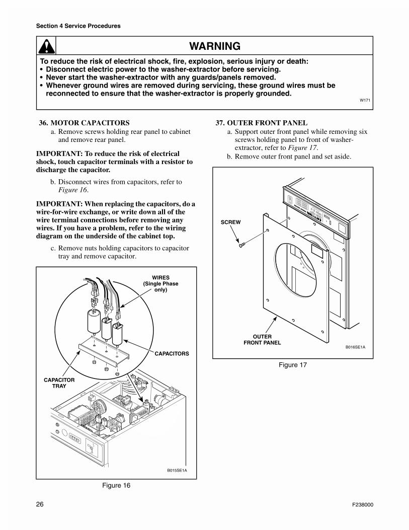
36. MOTOR CAPACITORSa. Remove screws holding rear panel to cabinet
and remove rear panel.
IMPORTANT: To reduce the risk of electrical shock, touch capacitor terminals with a resistor to discharge the capacitor.
b. Disconnect wires from capacitors, refer to Figure 16.
IMPORTANT: When replacing the capacitors, do a wire-for-wire exchange, or write down all of the wire terminal connections before removing any wires. If you have a problem, refer to the wiring diagram on the underside of the cabinet top.
c. Remove nuts holding capacitors to capacitor tray and remove capacitor.
37. OUTER FRONT PANELa. Support outer front panel while removing six
screws holding panel to front of washer-extractor, refer to Figure 17.
b. Remove outer front panel and set aside.
Figure 16
B015SE1A
WIRES(Single Phase
only)
CAPACITORS
CAPACITORTRAY
Figure 17
B016SE1A
OUTERFRONT PANEL
SCREW
26 F238000
Section 4 Service Procedures
To reduce the risk of electrical shock, fire, explosion, serious injury or death:• Disconnect electric power to the washer-extractor before servicing.• Never start the washer-extractor with any guards/panels removed.• Whenever ground wires are removed during servicing, these ground wires must be
reconnected to ensure that the washer-extractor is properly grounded.W171
WARNING
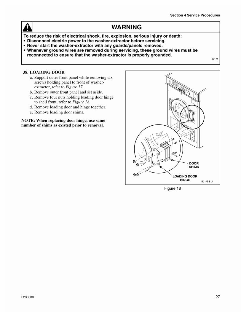
38. LOADING DOORa. Support outer front panel while removing six
screws holding panel to front of washer-extractor, refer to Figure 17.
b. Remove outer front panel and set aside.c. Remove four nuts holding loading door hinge
to shell front, refer to Figure 18.d. Remove loading door and hinge together.e. Remove loading door shims.
NOTE: When replacing door hinge, use same number of shims as existed prior to removal.
Figure 18
B017SE1A
DOORSHIMS
LOADING DOORHINGE
F238000 27
Section 4 Service Procedures
To reduce the risk of electrical shock, fire, explosion, serious injury or death:• Disconnect electric power to the washer-extractor before servicing.• Never start the washer-extractor with any guards/panels removed.• Whenever ground wires are removed during servicing, these ground wires must be
reconnected to ensure that the washer-extractor is properly grounded.W171
WARNING
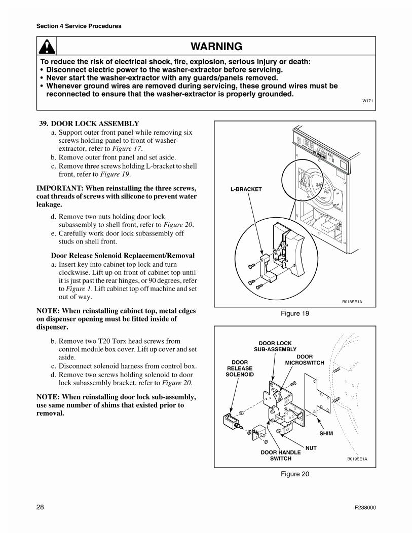
39. DOOR LOCK ASSEMBLYa. Support outer front panel while removing six
screws holding panel to front of washer-extractor, refer to Figure 17.
b. Remove outer front panel and set aside.c. Remove three screws holding L-bracket to shell
front, refer to Figure 19.
IMPORTANT: When reinstalling the three screws, coat threads of screws with silicone to prevent water leakage.
d. Remove two nuts holding door lock subassembly to shell front, refer to Figure 20.
e. Carefully work door lock subassembly off studs on shell front.
Door Release Solenoid Replacement/Removala. Insert key into cabinet top lock and turn
clockwise. Lift up on front of cabinet top until it is just past the rear hinges, or 90 degrees, refer to Figure 1. Lift cabinet top off machine and set out of way.
NOTE: When reinstalling cabinet top, metal edges on dispenser opening must be fitted inside of dispenser.
b. Remove two T20 Torx head screws from control module box cover. Lift up cover and set aside.
c. Disconnect solenoid harness from control box.d. Remove two screws holding solenoid to door
lock subassembly bracket, refer to Figure 20.
NOTE: When reinstalling door lock sub-assembly, use same number of shims that existed prior to removal.
Figure 19
Figure 20
B018SE1A
L-BRACKET
B019SE1A
DOOR LOCKSUB-ASSEMBLY
NUT
DOORRELEASESOLENOID
DOOR HANDLESWITCH
SHIM
DOORMICROSWITCH
28 F238000
Section 4 Service Procedures
To reduce the risk of electrical shock, fire, explosion, serious injury or death:• Disconnect electric power to the washer-extractor before servicing.• Never start the washer-extractor with any guards/panels removed.• Whenever ground wires are removed during servicing, these ground wires must be
reconnected to ensure that the washer-extractor is properly grounded.W171
WARNING
40. CYLINDER ASSEMBLYa. Insert key into cabinet top lock and turn
clockwise. Lift up on front of cabinet top until it is just past the rear hinges, or 90 degrees, refer to Figure 1. Lift cabinet top off machine and set out of way.
NOTE: When reinstalling cabinet top, metal edges on dispenser opening must be fitted inside of dispenser.
b. Remove two T20 Torx head screws from control module box cover. Lift up cover and set aside.
c. Remove screws holding rear panel to cabinet and remove rear panel.
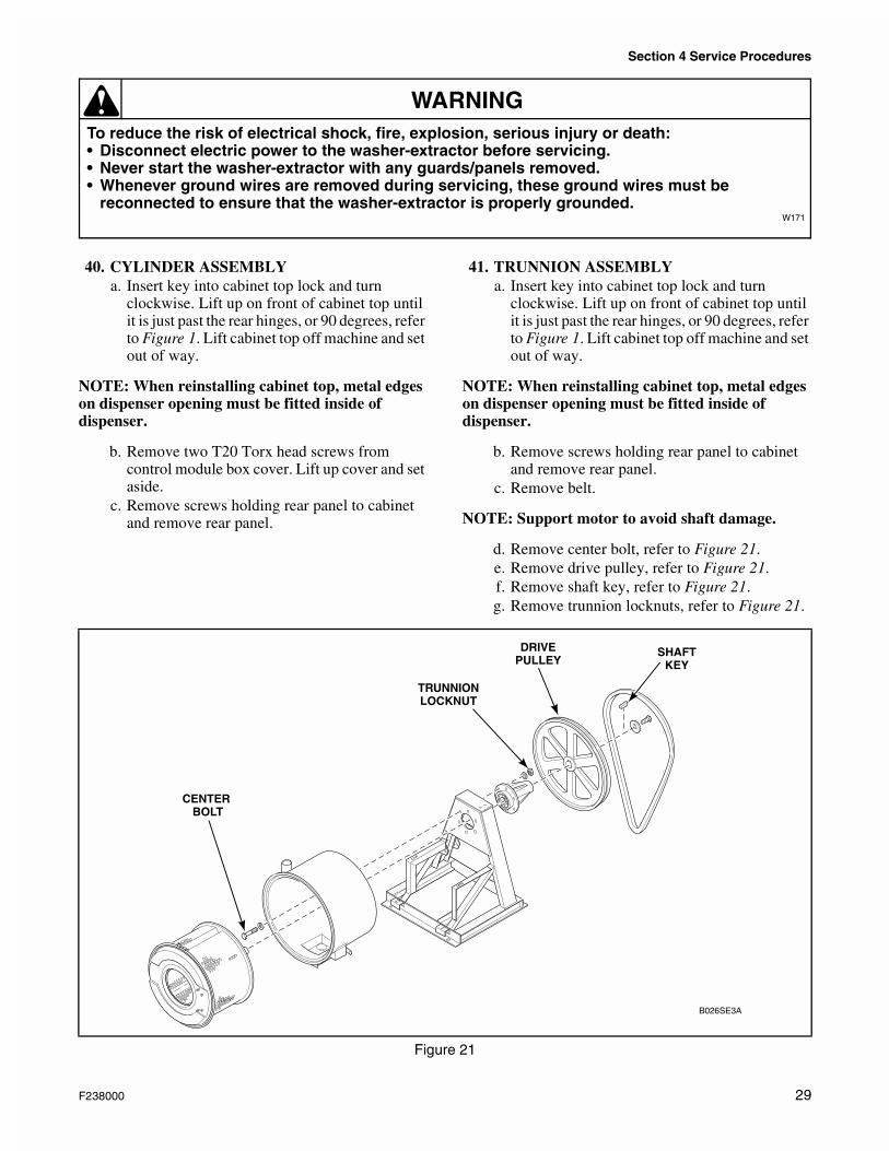
41. TRUNNION ASSEMBLYa. Insert key into cabinet top lock and turn
clockwise. Lift up on front of cabinet top until it is just past the rear hinges, or 90 degrees, refer to Figure 1. Lift cabinet top off machine and set out of way.
NOTE: When reinstalling cabinet top, metal edges on dispenser opening must be fitted inside of dispenser.
b. Remove screws holding rear panel to cabinet and remove rear panel.
c. Remove belt.
NOTE: Support motor to avoid shaft damage.
d. Remove center bolt, refer to Figure 21.e. Remove drive pulley, refer to Figure 21.f. Remove shaft key, refer to Figure 21.g. Remove trunnion locknuts, refer to Figure 21.
Figure 21
B026SE3A
CENTER BOLT
TRUNNIONLOCKNUT
DRIVEPULLEY
SHAFTKEY
F238000 29
Section 4 Service Procedures
To reduce the risk of electrical shock, fire, explosion, serious injury or death:• Disconnect electric power to the washer-extractor before servicing.• Never start the washer-extractor with any guards/panels removed.• Whenever ground wires are removed during servicing, these ground wires must be
reconnected to ensure that the washer-extractor is properly grounded.W171
WARNING
42. BEARINGS AND SEALSa. Disconnect machine from electrical power
source. Turn off water supply.b. Disconnect supply hoses and drain hose from
the rear of the machine.c. Insert key into cabinet top lock and turn
clockwise. Lift up on front of cabinet top until it is just past the rear hinges, or 90 degrees, refer to Figure 1. Lift cabinet top off machine and set out of way.
NOTE: When reinstalling cabinet top, metal edges on dispenser opening must be fitted inside of dispenser.
d. Remove screws holding rear panel to cabinet and remove rear panel.
e. Support outer front panel while removing six screws holding panel to front of washer-extractor, refer to Figure 17.
NOTE: On premise laundry machines use a magnetic switch mounted inside the outer front panel which must be disconnected before the front panel is removed.
f. Remove outer front panel and set aside.g. Remove four nuts holding loading door hinge
to shell front, refer to Figure 18.h. Remove loading door and hinge together.i. Loosen the hose clamp on the lower portion of
the large hose which connects the soap dispenser hose to the shell weldment. Pull the hose free.
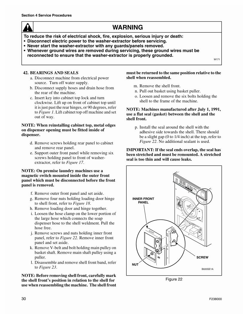
j. Remove screws and nuts holding inner front panel, refer to Figure 22. Remove inner front panel and set aside.
k. Remove V-belt and bolt holding main pulley on basket shaft. Remove main shaft pulley using a puller.
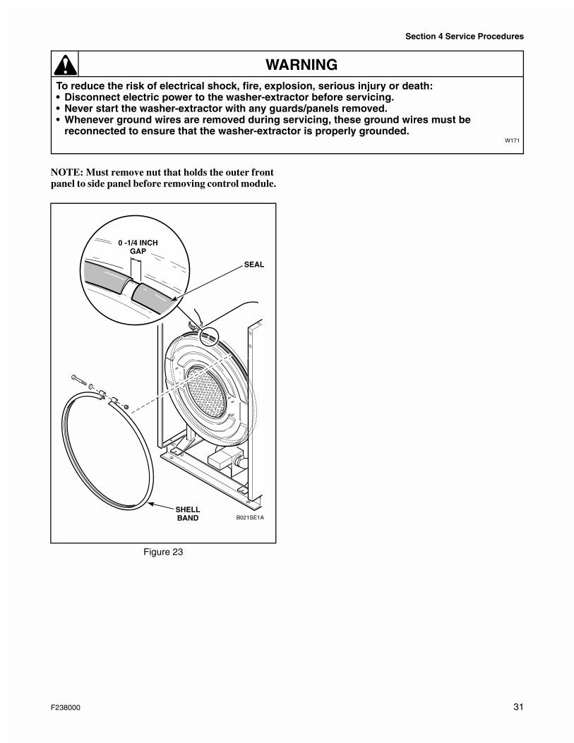
l. Disassemble and remove shell front band, refer to Figure 23.
NOTE: Before removing shell front, carefully mark the shell front’s position in relation to the shell for use when reassembling the machine. The shell front
must be returned to the same position relative to the shell when reassembled.
m. Remove the shell front.n. Pull out basket using basket puller.o. Loosen and remove the six bolts holding the
shell to the frame of the machine.
NOTE: Machines manufactured after July 1, 1991, use a flat seal (gasket) between the shell and the shell front.
p. Install the seal around the shell with the adhesive side towards the shell. There should be a slight gap (0 to 1/4 inch) at the top, refer to Figure 22. No additional sealant is used.
IMPORTANT: If the seal ends overlap, the seal has been stretched and must be remounted. A stretched seal is too thin and will cause leaks.
Figure 22
B020SE1A
INNER FRONTPANEL
SCREW
NUT
30 F238000
Section 4 Service Procedures
To reduce the risk of electrical shock, fire, explosion, serious injury or death:• Disconnect electric power to the washer-extractor before servicing.• Never start the washer-extractor with any guards/panels removed.• Whenever ground wires are removed during servicing, these ground wires must be
reconnected to ensure that the washer-extractor is properly grounded.W171
WARNING
NOTE: Must remove nut that holds the outer front panel to side panel before removing control module.
Figure 23
0 -1/4 INCHGAP
B021SE1A
SEAL
SHELLBAND
F238000 31