Embed Size (px)
Citation preview
© ⅯⅯⅩⅢ Kirby Morgan Dive Systems, Inc. All rights reserved. Document # 130311001 9
SuperLite® 17B
Chapter 2 Description & Operational Specifications - SuperLite®-17B
This section includes a detailed description of the SuperLite®-17 as well as important operational specifications.
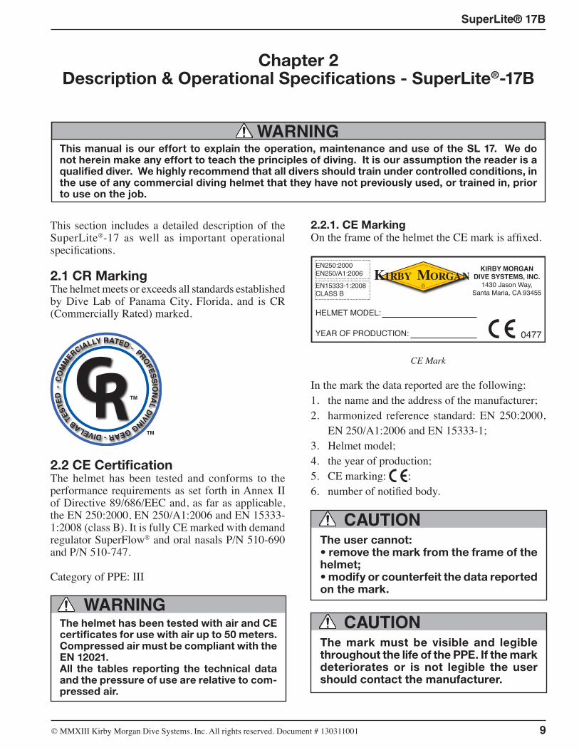
2.1 CR MarkingThe helmet meets or exceeds all standards established by Dive Lab of Panama City, Florida, and is CR (Commercially Rated) marked.
COM
MERCIALLY RATED - PROFESSIONAL DIVING GEAR - DIVELAB TE
STED
-
TM
TM
2.2 CE CertificationThe helmet has been tested and conforms to the performance requirements as set forth in Annex II of Directive 89/686/EEC and, as far as applicable, the EN 250:2000, EN 250/A1:2006 and EN 15333-1:2008 (class B). It is fully CE marked with demand regulator SuperFlow® and oral nasals P/N 510-690 and P/N 510-747.
Category of PPE: III
WARNINGThe helmet has been tested with air and CE certificates for use with air up to 50 meters. Compressed air must be compliant with the EN 12021.All the tables reporting the technical data and the pressure of use are relative to com-pressed air.
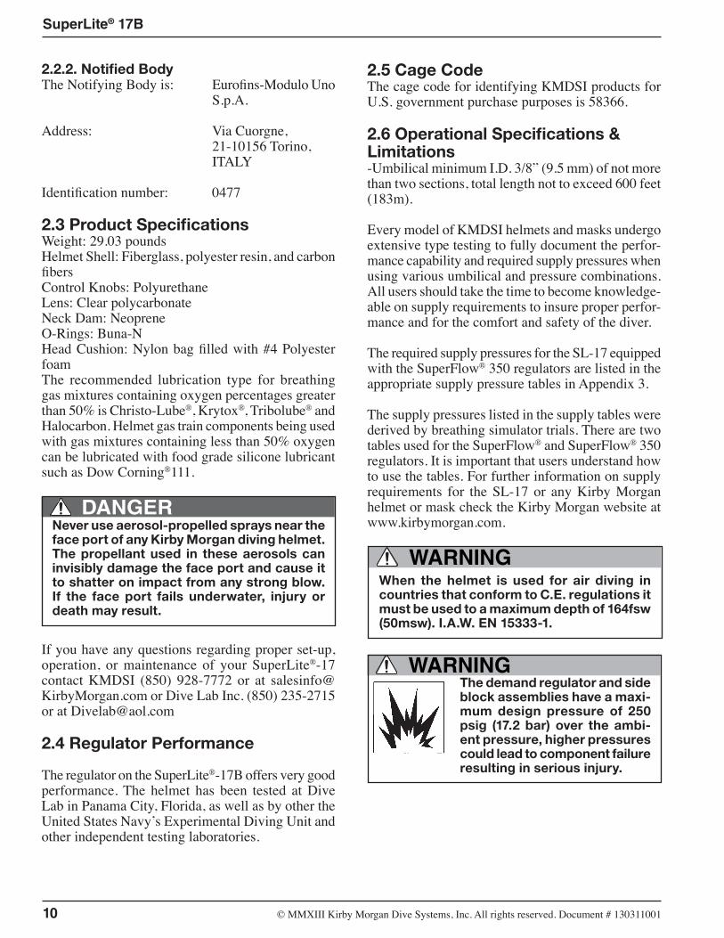
2.2.1. CE MarkingOn the frame of the helmet the CE mark is affixed.
0477
KIRBY MORGANDIVE SYSTEMS, INC.
1430 Jason Way,Santa Maria, CA 93455
EN250:2000EN250/A1:2006
EN15333-1:2008CLASS B
HELMET MODEL:
YEAR OF PRODUCTION:
CE Mark
In the mark the data reported are the following:1. the name and the address of the manufacturer;2. harmonized reference standard: EN 250:2000,
EN 250/A1:2006 and EN 15333-1;3. Helmet model;4. the year of production;5. CE marking: ;6. number of notified body.
CAUTIONThe user cannot:• remove the mark from the frame of the helmet;• modify or counterfeit the data reported on the mark.
CAUTIONThe mark must be visible and legible throughout the life of the PPE. If the mark deteriorates or is not legible the user should contact the manufacturer.
This manual is our effort to explain the operation, maintenance and use of the SL 17. We do not herein make any effort to teach the principles of diving. It is our assumption the reader is a qualified diver. We highly recommend that all divers should train under controlled conditions, in the use of any commercial diving helmet that they have not previously used, or trained in, prior to use on the job.
WARNING
10 © ⅯⅯⅩⅢ Kirby Morgan Dive Systems, Inc. All rights reserved. Document # 130311001
SuperLite® 17B
2.2.2. Notified BodyThe Notifying Body is: Eurofins-Modulo Uno S.p.A.
Address: Via Cuorgne, 21-10156 Torino, ITALY
Identification number: 0477
2.3 Product SpecificationsWeight: 29.03 poundsHelmet Shell: Fiberglass, polyester resin, and carbon fibersControl Knobs: PolyurethaneLens: Clear polycarbonateNeck Dam: NeopreneO-Rings: Buna-NHead Cushion: Nylon bag filled with #4 Polyester foamThe recommended lubrication type for breathing gas mixtures containing oxygen percentages greater than 50% is Christo-Lube®, Krytox®, Tribolube® and Halocarbon. Helmet gas train components being used with gas mixtures containing less than 50% oxygen can be lubricated with food grade silicone lubricant such as Dow Corning®111.
Never use aerosol-propelled sprays near the face port of any Kirby Morgan diving helmet. The propellant used in these aerosols can invisibly damage the face port and cause it to shatter on impact from any strong blow. If the face port fails underwater, injury or death may result.
DANGER
If you have any questions regarding proper set-up, operation, or maintenance of your SuperLite®-17 contact KMDSI (850) 928-7772 or at [email protected] or Dive Lab Inc. (850) 235-2715 or at [email protected]
2.4 Regulator Performance
The regulator on the SuperLite®-17B offers very good performance. The helmet has been tested at Dive Lab in Panama City, Florida, as well as by other the United States Navy’s Experimental Diving Unit and other independent testing laboratories.
2.5 Cage CodeThe cage code for identifying KMDSI products for U.S. government purchase purposes is 58366.
2.6 Operational Specifications & Limitations-Umbilical minimum I.D. 3/8” (9.5 mm) of not more than two sections, total length not to exceed 600 feet (183m).
Every model of KMDSI helmets and masks undergo extensive type testing to fully document the perfor-mance capability and required supply pressures when using various umbilical and pressure combinations. All users should take the time to become knowledge-able on supply requirements to insure proper perfor-mance and for the comfort and safety of the diver.
The required supply pressures for the SL-17 equipped with the SuperFlow® 350 regulators are listed in the appropriate supply pressure tables in Appendix 3.
The supply pressures listed in the supply tables were derived by breathing simulator trials. There are two tables used for the SuperFlow® and SuperFlow® 350 regulators. It is important that users understand how to use the tables. For further information on supply requirements for the SL-17 or any Kirby Morgan helmet or mask check the Kirby Morgan website at www.kirbymorgan.com.
WARNINGWhen the helmet is used for air diving in countries that conform to C.E. regulations it must be used to a maximum depth of 164fsw (50msw). I.A.W. EN 15333-1.
WARNINGThe demand regulator and side block assemblies have a maxi-mum design pressure of 250 psig (17.2 bar) over the ambi-ent pressure, higher pressures could lead to component failure resulting in serious injury.
© ⅯⅯⅩⅢ Kirby Morgan Dive Systems, Inc. All rights reserved. Document # 130311001 11
SuperLite® 17B
Decompression diving always involves the risk of decompression sickness. Omitted decompression due to a loss of the breath-ing gas supply or other accidents can cause serious injury or death. Use of a SL 17 cannot prevent this type of injury.
DANGER
It is important for the user/diver to take excessive currents into consideration. The Quad-Valve™ Exhaust PN#525-759 is now standard on the SuperLite 17B. Unlike the old latex double exhaust, the quad system is not limited to a maximum depth of 150 FSW (46 msw) due to exhalation pressure.
WARNING
-Temperature Limitations: Use at water temperatures below 33°F (1°C) requires the use of hot water shroud PN# 525-100 and hot water to help prevent icing of the demand regulator.
NOTE The Hot Water Shroud (Part #525-100) in conjunction with hot water to the diver should be used whenever diving operations are conducted using HEO2 at water temperatures less than 60°F (15.56°C) for the comfort of the diver. KMDSI further recommends that the shroud be used in conjunction with hot water to the diver whenever diving operations are conducted using air or mixed gas, in waters colder than 33°F (1°C) to reduce the possibility of demand regulator icing. NOTE: Usually the greatest danger of demand regulator icing will be encountered on deck when the surrounding air temperature is less than 32°F (0°C). This effect is primarily due to the refrigera-tion effect of breathing air pressure reduction, and the addition of moisture from the divers exhalation coming in contact with the topside air temperature. If diving where the water temperature is 33°F (1°C) or warmer but the topside air temperature is below freezing, (32°F (0°C) icing of the demand regulator is possible. To help eliminate the possibil-ity of freezing on the surface, warm water should be run over the exterior of the demand regulator prior to water entry, if the hot water system is not used.
Only equipment certified and tested according to EN 250/E DIN 58 642 may be used with the SL 17 helmet when conducting diving operations in European EC compliant countries.
The umbilical assembly should be composed of good quality diving hose that meets industry standards. Generally, gas hose will be married to the commu-nications wire, pneumofathometer hose, and strength member in a manner that will allow the strength member to receive all the strain. There are also good quality umbilicals available that are assembled at the factory using a twisted method which does not require marrying.
Regardless of the system used, the umbilical is the diver’s life line and should always be of excellent quality and maintained carefully.
WARNINGGas systems used to supply Kirby Morgan helmets and masks must be capable of sup-plying gas to the diver at the required pres-sure and flow rates as stated in the opera-tional specifications. The use of unregulated gas sources is extremely dangerous.
The use of standard SCUBA type regulators is unacceptable, as there are no provisions for adjusting the intermediate pressure to the diver. Only proven systems that allow for varying the gas supply pressure to the diver should be used for umbilical diving.
2.7 Helmet FeaturesAll Kirby Morgan diving helmets are manufactured by hand. Each step of the manufacturing process is carefully controlled to assure the customer a high quality, durable helmet that will function properly.
The SL 17 was developed in the late 1970s and it is still one of the most popular diving helmets in the world, a tribute to its timeless design.
The SL 17 incorporates an innovative locking system and the SuperFlow® adjustable demand regulator which provides an outstanding breathing gas flow during peak work output. The helmet consists of two pieces: the helmet shell/helmet ring and the neck dam/yoke assembly. The head cushion and yoke gives the diver a secure fit in the helmet. The fit and balance seats the helmet comfortably for long periods of time even when working in the face down position.
12 © ⅯⅯⅩⅢ Kirby Morgan Dive Systems, Inc. All rights reserved. Document # 130311001
SuperLite® 17B
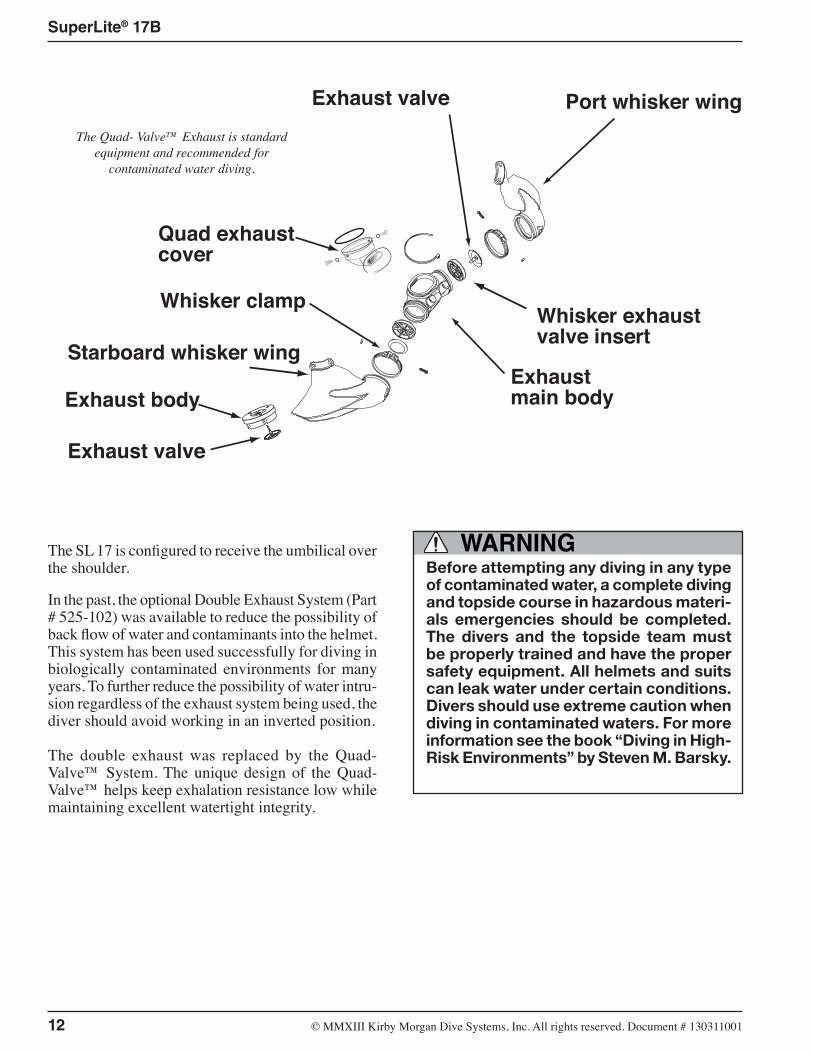
The SL 17 is configured to receive the umbilical over the shoulder. In the past, the optional Double Exhaust System (Part # 525-102) was available to reduce the possibility of back flow of water and contaminants into the helmet. This system has been used successfully for diving in biologically contaminated environments for many years. To further reduce the possibility of water intru-sion regardless of the exhaust system being used, the diver should avoid working in an inverted position.
The double exhaust was replaced by the Quad-Valve™ System. The unique design of the Quad-Valve™ helps keep exhalation resistance low while maintaining excellent watertight integrity.
WARNINGBefore attempting any diving in any type of contaminated water, a complete diving and topside course in hazardous materi-als emergencies should be completed. The divers and the topside team must be properly trained and have the proper safety equipment. All helmets and suits can leak water under certain conditions. Divers should use extreme caution when diving in contaminated waters. For more information see the book “Diving in High-Risk Environments” by Steven M. Barsky.
Exhaust body
Exhaust valve
Quad exhaustcover
Starboard whisker wing
Port whisker wing
Whisker exhaust valve insert
Exhaust valve
Exhaust main body
Whisker clamp
The Quad- Valve™ Exhaust is standard equipment and recommended for
contaminated water diving.
© ⅯⅯⅩⅢ Kirby Morgan Dive Systems, Inc. All rights reserved. Document # 130311001 13
SuperLite® 17B
When diving in heavy current (i.e. exceed-ing 3 knots) the single exhaust system on all KMDSI masks/helmets could allow water to enter, due to turbulence/eddy-ing. It is important for the user/diver to take excessive currents into consider-ation. The Quad-Valve™ Exhaust system will help prevent water intrusion when diving in heavy currents. Unlike the old double exhaust, the Quad-Valve™ does not limit the diving depth.
CAUTION
The Quad-Valve™ exhaust system is now standard equipment for the SL 17. This superior exhaust sys-tem has exceptionally low exhalation resistance, and helps to keep the helmet free of contaminants in pol-luted water. The Quad-Valve™ isolates the breathing system from the surrounding water with a four valve, low breathing resistance design (Patents Pending).
The Quad-Valve™ is designed to couple the regulator exhaust with the helmet main exhaust and route them into a single plenum chamber, mounted between the regulator body and main exhaust body. The exhaust gas then must pass through either one of two (or both) exhaust valves that are part of the bubble deflector (whisker wing). By having an exhaust valve in both sides of the bubble deflector, exhalation resistance is minimized, while still helping to maintain the isola-tion of the main helmet and regulator exhaust valves.
Other helmet features which are common to all KMDSI helmets include: • the face port and retainer ring • basic communications components • the oral nasal mask • the nose block device • the air train • most demand regulator components Many of the breathing system components on these helmets are also compatible with the KMB 18B and 28B. This helps reduce the inventory of spare parts that must be carried by commercial diving compa-nies.
Each step of the manufacturing process is carefully controlled to assure the customer of a high quality,
durable helmet that will function properly. The fol-lowing is a general description of the features of the SL 17.
1) The fiberglass shell face port (or view port) area remains unchanged. The side block and bent tube assembly that transports air/gas to the demand regu-lator from the side block are also the same. Most of the components in these areas are interchangeable between the 17B and models 27, 37, 47, and 57.
2) The neck dam on the SL 17 is secured by the neck clamp. Replacement neck dams install easily.
3) The head cushion attaches just inside the bottom of the helmet, keeping it in place when the diver dons the hat. The standard head cushion consists of a brushed nylon bag with an open cel polyester foam inside. Only genuine Kirby Morgan SL 17 head cushions should be used to ensure proper operation and comfort.
4) The handle that is fitted to the top of the SL 17 and the port weight are areas that can be used as mounting brackets for lights, TV cameras, etc.
2.8 General Description2.8.1 Helmet ShellThe helmet shell is fabricated of noncorrosive, rigid fiberglass which will not carry an electrical charge. This shell is the central structure for mounting all the components that make up the complete helmet. It is designed to allow easy replacement of parts when necessary. Any repair to the helmet shell must be done at an approved KMDSI repair center.
2.8.2 Gas Flow SystemsThe main gas supply flow from the umbilical enters the system at the adapter and flows through the one way valve to the interior of the side block. The one way valve or “non-return” is a very important com-ponent.
It prevents the flow of gas out of the helmet to the umbilical in the event of a sudden lowering of pres-sure in the supply hose. This can happen due to an accidental break in the hose or a fitting near the surface. Not only would the Auxiliary gas be lost if the one way valve failed (concurrent with a hose or fitting break on deck), but the diver could suffer from a serious “squeeze” that could cause injury or death.
14 © ⅯⅯⅩⅢ Kirby Morgan Dive Systems, Inc. All rights reserved. Document # 130311001
SuperLite® 17B
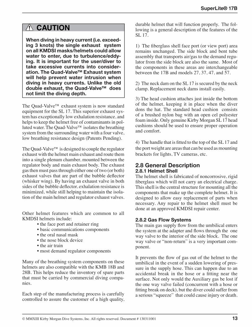
The SuperLite® 17B helmet CO
MM
ERCIALLY RATED - PROFE
SS
ION
AL D
IVING GEAR - DIVELAB TE
ST
ED
™
Defog Free Flow Valve Knob
Regulator Adjustment Knob
Equalization Device
Oral Nasal Mask
Port Retainer
Handle
Purge Button
Helmet Shell
Neck Clamp Assembly
Latch Catch Mechanism
Quad-Valve™ Exhaust (standard on all Kirby Morgan 37
helmets from 2005 on)
Sideblock
Rear Weight
EGS Valve
Neck Dam
Weight
Non-Return Valve
© ⅯⅯⅩⅢ Kirby Morgan Dive Systems, Inc. All rights reserved. Document # 130311001 15
SuperLite® 17B
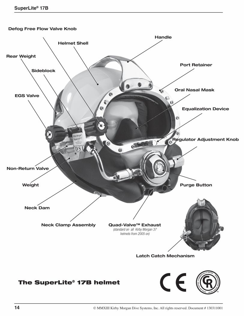
Although we have selected the valve for its reli-ability and quality, inspection and maintenance of this valve must be done regularly. It is very easy to disassemble and inspect. (A rebuild kit for this valve is Part #525-330).
Gas Flow To Air Train
Main Gas Supply
Auxiliary L.P. Port
Gas Flow To Regulator
WARNINGThe one way valve must be tested daily, prior to the commencement of diving operations. Failure of one way valve could cause serious injury or death. Follow the procedures for testing the valve in this manual.
The emergency gas comes from a tank of compressed gas worn by the diver. It enters the system through the Emergency Gas valve when the diver turns the control knob on. The flow then enters the side block.
Both sources of gas flow through the same passage in the side block body to two exits. One exit is always open to supply gas to the demand regulator assembly. The other exit is to the defogger valve (free-flow valve) assembly.
The diver controls the flow of gas through the defog-ger system with the control knob. The gas enters the helmet and flows through the air train which directs the gas onto the face port to help eliminate or clear fogging of the faceplate that forms from the diver’s warm breath.
The flow continues out through the water dump (hel-met exhaust) valve, or into the oral nasal by means of the valve, then into the regulator and out through the regulator exhaust to the Quad-Valve™ whiskers. The diver can breathe from this flow of gas if the demand regulator malfunctions.
Returning to the side block assembly: the other pas-sage for gas is to the demand regulator. It goes to a bent tube assembly that connects to the inlet nipple of the demand regulator. The flow of gas in the demand regulator assembly is controlled by the inlet valve that supplies gas to the diver on inhalation “demand” only, and shuts off during the exhalation cycle. The SuperFlow® demand regulator senses the start of the divers inhalation and opens the inlet valve, matching the diver’s need. The regulator continues to match the diver’s inhalation as the rate increases, peaks, then ebbs and stops.
When the diver exhales, the supply gas stays off as the exhalation gas flows through the regulator body, out the regulator exhaust valve, through the Quad-Valve™ whiskers, and out into the water. The whiskers deflect the exhaust bubbles away from the face port to keep the diver’s view clear.
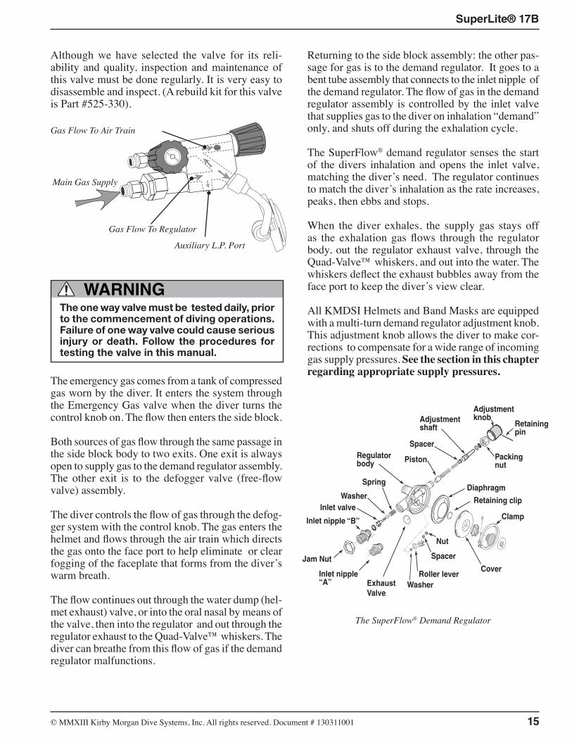
All KMDSI Helmets and Band Masks are equipped with a multi-turn demand regulator adjustment knob. This adjustment knob allows the diver to make cor-rections to compensate for a wide range of incoming gas supply pressures. See the section in this chapter regarding appropriate supply pressures.
Adjustmentknob
Regulatorbody
Diaphragm
Cover
ClampInlet valve
Adjustmentshaft
Packingnut
Piston
Spacer
Roller lever
Spacer
Nut
Inlet nipple “B”
Retainingpin
Spring
WasherInlet nipple “A”
Retaining clip
Jam Nut
ExhaustValve
Washer
The SuperFlow® Demand Regulator
16 © ⅯⅯⅩⅢ Kirby Morgan Dive Systems, Inc. All rights reserved. Document # 130311001
SuperLite® 17B
DANGERNever connect the main gas supply hose from the diving station/umbilical to the emer-gency valve. There is no one way valve in the emergency valve. If this mistake is made, any break in the supply hose could possibly result in a “squeeze”.
This could result in serious injury or death.
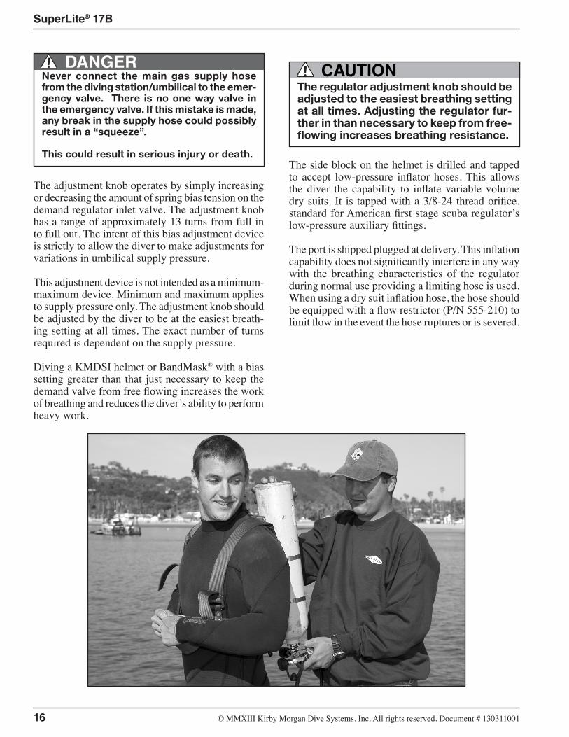
The adjustment knob operates by simply increasing or decreasing the amount of spring bias tension on the demand regulator inlet valve. The adjustment knob has a range of approximately 13 turns from full in to full out. The intent of this bias adjustment device is strictly to allow the diver to make adjustments for variations in umbilical supply pressure.
This adjustment device is not intended as a minimum-maximum device. Minimum and maximum applies to supply pressure only. The adjustment knob should be adjusted by the diver to be at the easiest breath-ing setting at all times. The exact number of turns required is dependent on the supply pressure.
Diving a KMDSI helmet or BandMask® with a bias setting greater than that just necessary to keep the demand valve from free flowing increases the work of breathing and reduces the diver’s ability to perform heavy work.
The regulator adjustment knob should be adjusted to the easiest breathing setting at all times. Adjusting the regulator fur-ther in than necessary to keep from free-flowing increases breathing resistance.
CAUTION
The side block on the helmet is drilled and tapped to accept low-pressure inflator hoses. This allows the diver the capability to inflate variable volume dry suits. It is tapped with a 3/8-24 thread orifice, standard for American first stage scuba regulator’s low-pressure auxiliary fittings.
The port is shipped plugged at delivery. This inflation capability does not significantly interfere in any way with the breathing characteristics of the regulator during normal use providing a limiting hose is used. When using a dry suit inflation hose, the hose should be equipped with a flow restrictor (P/N 555-210) to limit flow in the event the hose ruptures or is severed.
© ⅯⅯⅩⅢ Kirby Morgan Dive Systems, Inc. All rights reserved. Document # 130311001 17
SuperLite® 17B
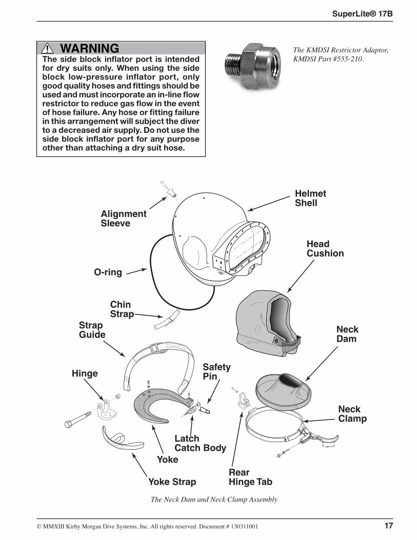
HelmetShell
HeadCushion
NeckDam
NeckClamp
Yoke
O-ring
ChinStrap
RearHinge TabYoke Strap
StrapGuide
Safety Pin
AlignmentSleeve
LatchCatch Body
Hinge
WARNINGThe side block inflator port is intended for dry suits only. When using the side block low-pressure inflator port, only good quality hoses and fittings should be used and must incorporate an in-line flow restrictor to reduce gas flow in the event of hose failure. Any hose or fitting failure in this arrangement will subject the diver to a decreased air supply. Do not use the side block inflator port for any purpose other than attaching a dry suit hose.
The KMDSI Restrictor Adaptor, KMDSI Part #555-210.
The Neck Dam and Neck Clamp Assembly
18 © ⅯⅯⅩⅢ Kirby Morgan Dive Systems, Inc. All rights reserved. Document # 130311001
SuperLite® 17B
When using the side block low pressure inflator port, the diver should only use high quality hoses with an integrated flow restrictor or a KMDSI flow restrictor PN# 555-210. All hoses must have an in-line restrictor to reduce the gas flow in the event of hose failure.
Do not use fitting adapters. Standard adapters do not provide an adequate flow restriction. The use of many off the shelf adapters on the side block assem-bly could expose the low pressure hose fittings to excessive stress. Any failure of an inflation hose will subject the diver to a decreased supply pressure.
WARNING
2.8.3 Emergency Gas Supply System (EGS)KMDSI strongly recommends that the working diver carry an independent supply of compressed gas (or air) fitted with a first stage regulator and hose that is connected to the inlet of the Emergency Gas Valve (EGV).
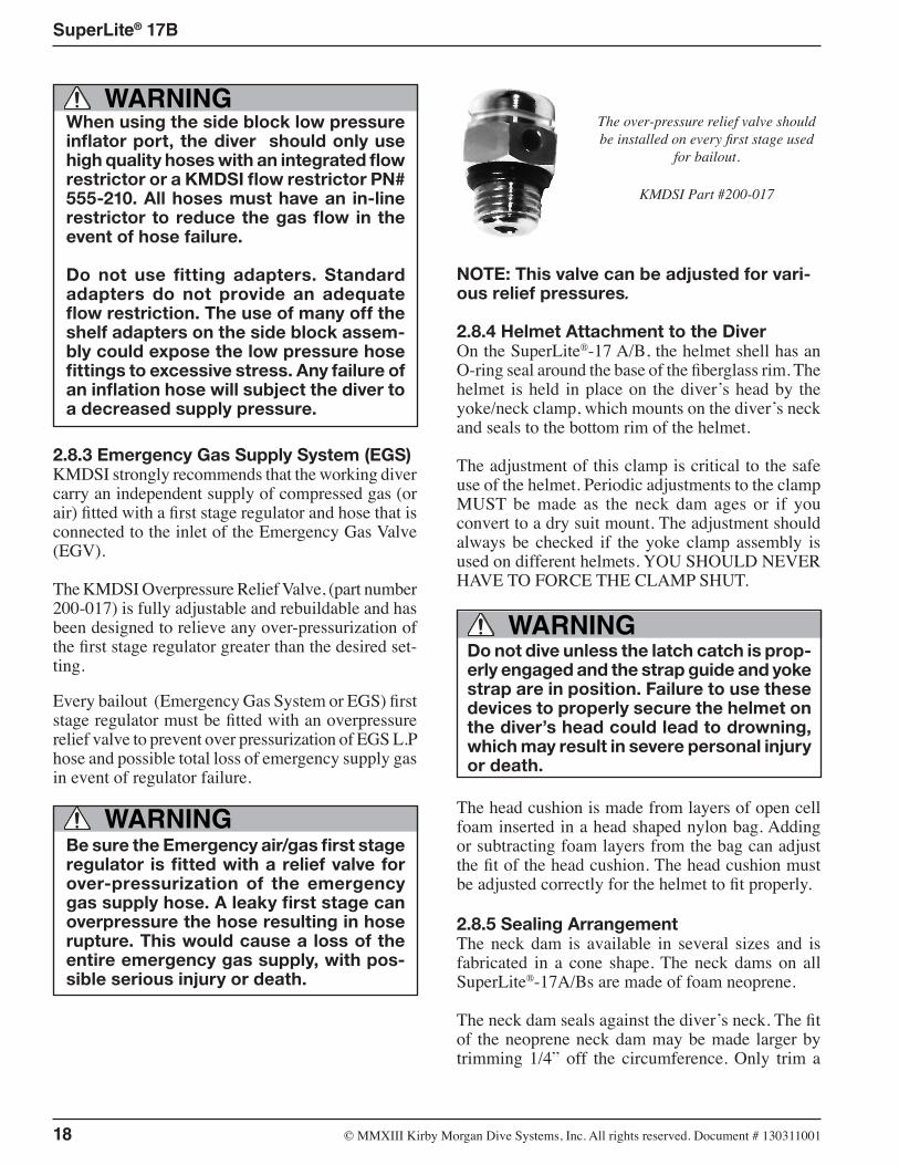
The KMDSI Overpressure Relief Valve, (part number 200-017) is fully adjustable and rebuildable and has been designed to relieve any over-pressurization of the first stage regulator greater than the desired set-ting.
Every bailout (Emergency Gas System or EGS) first stage regulator must be fitted with an overpressure relief valve to prevent over pressurization of EGS L.P hose and possible total loss of emergency supply gas in event of regulator failure.
WARNINGBe sure the Emergency air/gas first stage regulator is fitted with a relief valve for over-pressurization of the emergency gas supply hose. A leaky first stage can overpressure the hose resulting in hose rupture. This would cause a loss of the entire emergency gas supply, with pos-sible serious injury or death.
The over-pressure relief valve should be installed on every first stage used
for bailout.
KMDSI Part #200-017
NOTE: This valve can be adjusted for vari-ous relief pressures.
2.8.4 Helmet Attachment to the DiverOn the SuperLite®-17 A/B, the helmet shell has an O-ring seal around the base of the fiberglass rim. The helmet is held in place on the diver’s head by the yoke/neck clamp, which mounts on the diver’s neck and seals to the bottom rim of the helmet.
The adjustment of this clamp is critical to the safe use of the helmet. Periodic adjustments to the clamp MUST be made as the neck dam ages or if you convert to a dry suit mount. The adjustment should always be checked if the yoke clamp assembly is used on different helmets. YOU SHOULD NEVER HAVE TO FORCE THE CLAMP SHUT.
Do not dive unless the latch catch is prop-erly engaged and the strap guide and yoke strap are in position. Failure to use these devices to properly secure the helmet on the diver’s head could lead to drowning, which may result in severe personal injury or death.
WARNING
The head cushion is made from layers of open cell foam inserted in a head shaped nylon bag. Adding or subtracting foam layers from the bag can adjust the fit of the head cushion. The head cushion must be adjusted correctly for the helmet to fit properly.
2.8.5 Sealing ArrangementThe neck dam is available in several sizes and is fabricated in a cone shape. The neck dams on all SuperLite®-17A/Bs are made of foam neoprene.
The neck dam seals against the diver’s neck. The fit of the neoprene neck dam may be made larger by trimming 1/4” off the circumference. Only trim a
© ⅯⅯⅩⅢ Kirby Morgan Dive Systems, Inc. All rights reserved. Document # 130311001 19
SuperLite® 17B
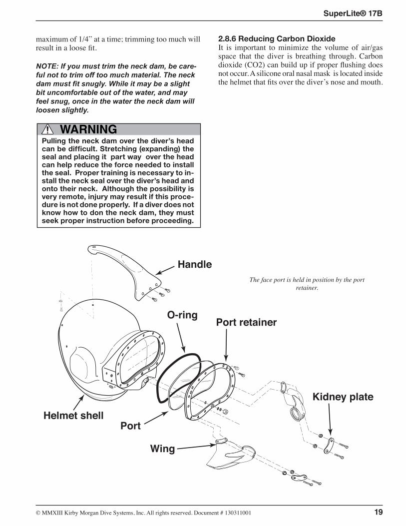
Handle
O-ringPort retainer
PortHelmet shell
Wing
Kidney plate
maximum of 1/4” at a time; trimming too much will result in a loose fit.
NOTE: If you must trim the neck dam, be care-ful not to trim off too much material. The neck dam must fit snugly. While it may be a slight bit uncomfortable out of the water, and may feel snug, once in the water the neck dam will loosen slightly.
WARNINGPulling the neck dam over the diver’s head can be difficult. Stretching (expanding) the seal and placing it part way over the head can help reduce the force needed to install the seal. Proper training is necessary to in-stall the neck seal over the diver’s head and onto their neck. Although the possibility is very remote, injury may result if this proce-dure is not done properly. If a diver does not know how to don the neck dam, they must seek proper instruction before proceeding.
2.8.6 Reducing Carbon DioxideIt is important to minimize the volume of air/gas space that the diver is breathing through. Carbon dioxide (CO2) can build up if proper flushing does not occur. A silicone oral nasal mask is located inside the helmet that fits over the diver’s nose and mouth.
The face port is held in position by the port retainer.
20 © ⅯⅯⅩⅢ Kirby Morgan Dive Systems, Inc. All rights reserved. Document # 130311001
SuperLite® 17B
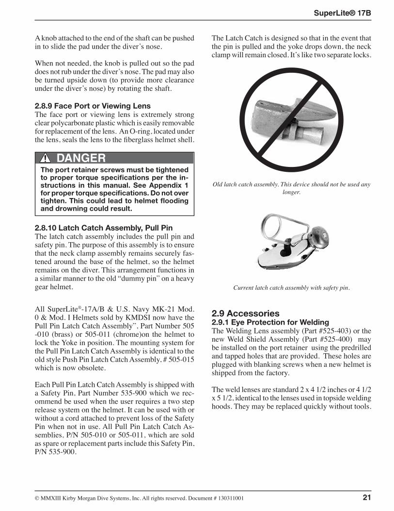
NeckDam
NeckClamp
YokeRearHinge Tab
Safety Pin
LatchCatch Body
Hinge
The yoke and latch catch assembly must work properly together.
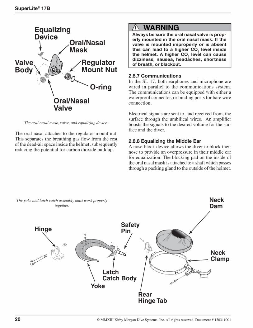
Oral/Nasal Mask
RegulatorMount Nut
O-ring
EqualizingDevice
ValveBody
Oral/NasalValve
The oral nasal mask, valve, and equalizing device.
The oral nasal attaches to the regulator mount nut. This separates the breathing gas flow from the rest of the dead-air space inside the helmet, subsequently reducing the potential for carbon dioxide buildup.
WARNINGAlways be sure the oral nasal valve is prop-erly mounted in the oral nasal mask. If the valve is mounted improperly or is absent this can lead to a higher CO2 level inside the helmet. A higher CO2 level can cause dizziness, nausea, headaches, shortness of breath, or blackout.
2.8.7 CommunicationsIn the SL 17, both earphones and microphone are wired in parallel to the communications system. The communications can be equipped with either a waterproof connector, or binding posts for bare wire connection.
Electrical signals are sent to, and received from, the surface through the umbilical wires. An amplifier boosts the signals to the desired volume for the sur-face and the diver.
2.8.8 Equalizing the Middle EarA nose block device allows the diver to block their nose to provide an overpressure in their middle ear for equalization. The blocking pad on the inside of the oral nasal mask is attached to a shaft which passes through a packing gland to the outside of the helmet.
© ⅯⅯⅩⅢ Kirby Morgan Dive Systems, Inc. All rights reserved. Document # 130311001 21
SuperLite® 17B
A knob attached to the end of the shaft can be pushed in to slide the pad under the diver’s nose.
When not needed, the knob is pulled out so the pad does not rub under the diver’s nose. The pad may also be turned upside down (to provide more clearance under the diver’s nose) by rotating the shaft.
2.8.9 Face Port or Viewing LensThe face port or viewing lens is extremely strong clear polycarbonate plastic which is easily removable for replacement of the lens. An O-ring, located under the lens, seals the lens to the fiberglass helmet shell.
DANGERThe port retainer screws must be tightened to proper torque specifications per the in-structions in this manual. See Appendix 1 for proper torque specifications. Do not over tighten. This could lead to helmet flooding and drowning could result.
2.8.10 Latch Catch Assembly, Pull PinThe latch catch assembly includes the pull pin and safety pin. The purpose of this assembly is to ensure that the neck clamp assembly remains securely fas-tened around the base of the helmet, so the helmet remains on the diver. This arrangement functions in a similar manner to the old “dummy pin” on a heavy gear helmet.
All SuperLite®-17A/B & U.S. Navy MK-21 Mod. 0 & Mod. I Helmets sold by KMDSI now have the Pull Pin Latch Catch Assembly”, Part Number 505 -010 (brass) or 505-011 (chrome)on the helmet to lock the Yoke in position. The mounting system for the Pull Pin Latch Catch Assembly is identical to the old style Push Pin Latch Catch Assembly, # 505-015 which is now obsolete.
Each Pull Pin Latch Catch Assembly is shipped with a Safety Pin, Part Number 535-900 which we rec-ommend be used when the user requires a two step release system on the helmet. It can be used with or without a cord attached to prevent loss of the Safety Pin when not in use. All Pull Pin Latch Catch As-semblies, P/N 505-010 or 505-011, which are sold as spare or replacement parts include this Safety Pin, P/N 535-900.
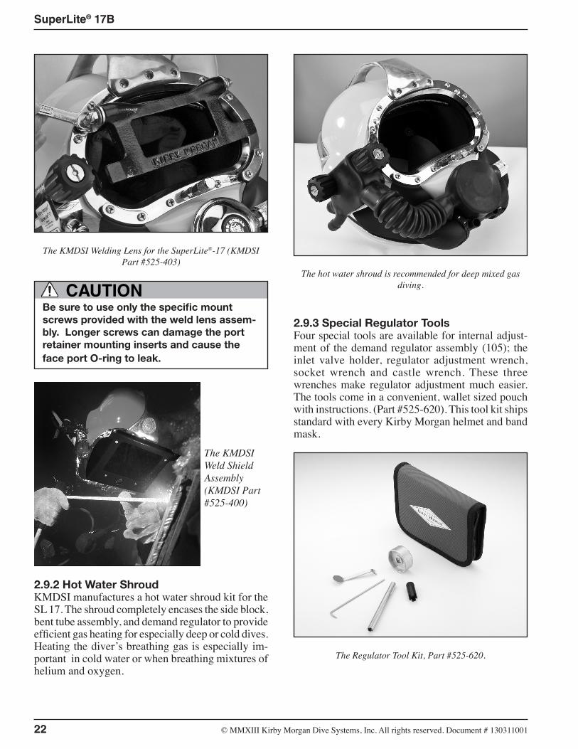
The Latch Catch is designed so that in the event that the pin is pulled and the yoke drops down, the neck clamp will remain closed. It’s like two separate locks.
Old latch catch assembly. This device should not be used any longer.
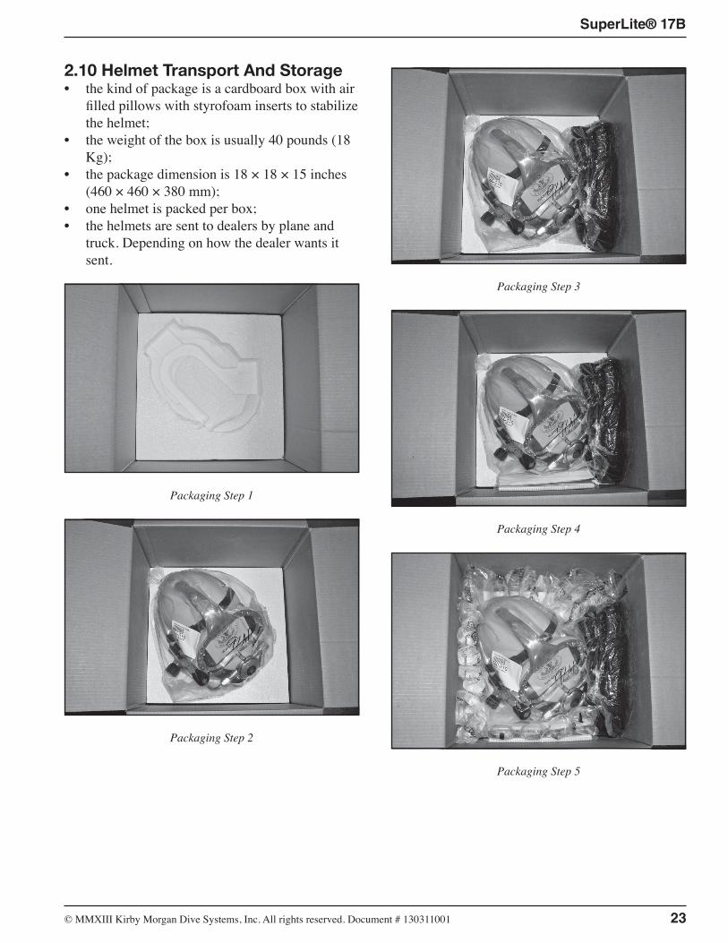
Current latch catch assembly with safety pin.
2.9 Accessories2.9.1 Eye Protection for WeldingThe Welding Lens assembly (Part #525-403) or the new Weld Shield Assembly (Part #525-400) may be installed on the port retainer using the predrilled and tapped holes that are provided. These holes are plugged with blanking screws when a new helmet is shipped from the factory.
The weld lenses are standard 2 x 4 1/2 inches or 4 1/2 x 5 1/2, identical to the lenses used in topside welding hoods. They may be replaced quickly without tools.
22 © ⅯⅯⅩⅢ Kirby Morgan Dive Systems, Inc. All rights reserved. Document # 130311001
SuperLite® 17B
The KMDSI Welding Lens for the SuperLite®-17 (KMDSI Part #525-403)
Be sure to use only the specific mount screws provided with the weld lens assem-bly. Longer screws can damage the port retainer mounting inserts and cause the face port O-ring to leak.
CAUTION
The KMDSI Weld Shield Assembly (KMDSI Part #525-400)
2.9.2 Hot Water ShroudKMDSI manufactures a hot water shroud kit for the SL 17. The shroud completely encases the side block, bent tube assembly, and demand regulator to provide efficient gas heating for especially deep or cold dives. Heating the diver’s breathing gas is especially im-portant in cold water or when breathing mixtures of helium and oxygen.
The hot water shroud is recommended for deep mixed gas diving.
2.9.3 Special Regulator ToolsFour special tools are available for internal adjust-ment of the demand regulator assembly (105); the inlet valve holder, regulator adjustment wrench, socket wrench and castle wrench. These three wrenches make regulator adjustment much easier. The tools come in a convenient, wallet sized pouch with instructions. (Part #525-620). This tool kit ships standard with every Kirby Morgan helmet and band mask.
The Regulator Tool Kit, Part #525-620.
© ⅯⅯⅩⅢ Kirby Morgan Dive Systems, Inc. All rights reserved. Document # 130311001 23
SuperLite® 17B
2.10 Helmet Transport And Storage• the kind of package is a cardboard box with air
filled pillows with styrofoam inserts to stabilize the helmet;
• the weight of the box is usually 40 pounds (18 Kg);
• the package dimension is 18 × 18 × 15 inches (460 × 460 × 380 mm);
• one helmet is packed per box;• the helmets are sent to dealers by plane and
truck. Depending on how the dealer wants it sent.
Packaging Step 1
Packaging Step 2
Packaging Step 3
Packaging Step 4
Packaging Step 5
24 © ⅯⅯⅩⅢ Kirby Morgan Dive Systems, Inc. All rights reserved. Document # 130311001
SuperLite® 17B
Packaging Step 6
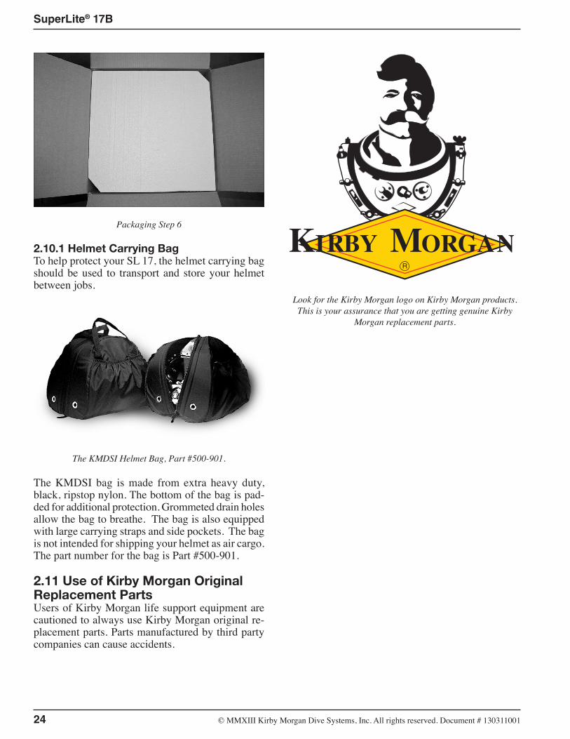
2.10.1 Helmet Carrying BagTo help protect your SL 17, the helmet carrying bag should be used to transport and store your helmet between jobs.
The KMDSI Helmet Bag, Part #500-901.
The KMDSI bag is made from extra heavy duty, black, ripstop nylon. The bottom of the bag is pad-ded for additional protection. Grommeted drain holes allow the bag to breathe. The bag is also equipped with large carrying straps and side pockets. The bag is not intended for shipping your helmet as air cargo. The part number for the bag is Part #500-901.
2.11 Use of Kirby Morgan Original Replacement PartsUsers of Kirby Morgan life support equipment are cautioned to always use Kirby Morgan original re-placement parts. Parts manufactured by third party companies can cause accidents.
Look for the Kirby Morgan logo on Kirby Morgan products. This is your assurance that you are getting genuine Kirby
Morgan replacement parts.