Embed Size (px)
Citation preview
183 Water Street • New Haven, CT 06511 • Phone (203) 776-0473 • FAX (203) 773-1019 • www.hydrolevel.com
MODEL 3000220°F (104°C) Max High LimitMODEL 3000-190190°F (88°C) Max High Limit
High Temp Limit / LWCO Controlwith Thermal Targeting™
for Gas Water Boilers24 VAC Operating Voltage
PATENT NO. 7,891,572
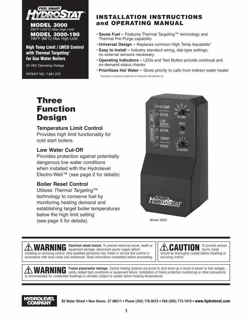
ThreeFunctionDesignTemperature Limit ControlProvides high limit functionality forcold start boilers.Low Water Cut-OffProvides protection against potentiallydangerous low water conditionswhen installed with the HydrolevelElectro-Well™ (see page 2 for details).Boiler Reset ControlUtilizes Thermal Targeting™technology to conserve fuel bymonitoring heating demand andestablishing target boiler temperaturesbelow the high limit setting(see page 5 for details).
INSTALLATION INSTRUCTIONSand OPERATING MANUAL
• Saves Fuel – Features Thermal Targeting™ technology andThermal Pre-Purge capability
• Universal Design – Replaces common High Temp Aquastats*• Easy to Install – Industry standard wiring, dial-type settings,
no external sensors necessary• Operating Indicators – LEDs and Test Button provide continual and
on-demand status checks• Prioritizes Hot Water – Gives priority to calls from indirect water heater• *Aquastat is a registered trademark of Honeywell International, Inc.
WARNING Electrical shock hazard. To prevent electrical shock, death orequipment damage, disconnect power supply before
installing or servicing control. Only qualified personnel may install or service this control inaccordance with local codes and ordinances. Read instructions completely before proceeding.
CAUTION To prevent seriousburns, boiler
should be thoroughly cooled before installing orservicing control.
WARNING Frozen pipes/water damage. Central heating systems are prone to shut down as a result of power or fuel outages,safety related fault conditions or equipment failure. Installation of freeze protection monitoring or other precautions
is recommended for unattended dwellings in climates subject to sustain below-freezing temperatures.
Model 3000

2
MOUNTING THE CONTROL
STEP 1 Insert sensor ALL THE WAY into well. (Fig. 1)
STEP 2 Place control on the well.While holding box against well nut,tighten well clamp screw. (Fig. 2)
FIG. 2
FIG. 1
NOTE: In the case of space restrictions,the Fuel Smart HydroStat control maybe mounted in a horizontal orientationwithout any loss of function.
IMPORTANT Make sure that the immersion well or Electro-Well™ is installed in the boiler manufacturer’s designatedtemperature limit control tapping.
NNOOTTEE:: If installing an Electro-Well, pipe sealing compound should be used. Teflon tape is not recommended.
IMMERSION WELLS
IMPORTANT: For proper operation of the low water cut-off function, theremust be a minimum of ½" clearance between the copper well tube and anysurface within the boiler.
See Electro-Well models on page 8.
NOTE: When installed on a standard immersion well, the “LWCO Active”LED will not illuminate.
Fuel Smart HydroStat can be installed on an existing immersion well already in the boiler or on a Hydrolevel Electro-Well™ (sold separately). The low water cut-off function is automatically activated when installed on an Electro-Well™. IMPORTANT: The control will not provide low water cut-off protection when installed on a standard immersion well.NOTE: Do not use heat-conducting grease.
Fuel Smart HydroStat installed with Hydrolevel Electro-Well™
Fuel Smart HydroStat installed with standard immersion well

3
WARNING Electrical shock hazard. To prevent electrical shock, death or equipment damage, disconnect power supply before installing or servicing this control.
WIRING TO CONTROL CENTER
USE CABLE 1 – For boilers equipped with a Honeywell R8285 Control Center or equivalent.
USE CABLE 2 – For Thermal Targeting and is optional. If Cable 2 is not used, turn Economy OFF.IMPORTANT: When installing with an indirect water heater, the indirect wiring cable will bypass the Thermal Targeting feature and allow the boiler to fire to thehigh limit setting to heat the indirect tank. The indirect signal must be separate from all heating zone signals. If you choose not to separate the indirect signal fromthe heating zones, the Economy Feature should be turned OFF to insure that the boiler supplies adequate temperature to heat the indirect tank (see page 5).
Y G W
C R
Connect the WHITE wire to C and the RED wire to Rusing the screw terminals on the control center.
Unplug the factory-wired quick connect from termi-nal Y and plug into YELLOW wire with male con-nector. � Plug YELLOW wire from cable with femaleconnector into terminal Y.
Step � Step �
Y G W
C R
Y G W
C R
Step � Step �
Connect the WHITE wire to G and the RED wire to Rusing the screw terminals on the control center. TheRED and WHITE wires must be connected in parallelwith the heating thermostat.
Connect the two YELLOW wires to the end switchfrom the indirect water heater relay. NOTE: If you arenot connecting to an indirect water heater, the bareends of the YELLOW wires must be capped off sepa-rately with wire nuts.

4
WARNING Electrical shock hazard. To prevent electrical shock, death or equipment damage, disconnect power supply before installing or servicing this control.
WIRING TO IGNITION CONTROL MODULE
TO INDIRECT
WATERHEATER
FROM THERMOSTAT
INPUT ONCONTROLMODULE
#45-531-56Wire
Harness
For use on boilers equipped with Integrated Boiler Control Module
CABLE 1 — Disconnect boiler wire Harness from the “SECONDARY” port on the Integrated Control Moduleand plug into female plug adapter on #45-531-56 Wire Harness. � Plug male adapter on #45-531-56 WireHarness into “SECONDARY” port on the Integrated Control Module. � Plug the other end of the Wire Harnessinto the Model 3000 Low Water Cut-Off. � Connect the yellow wires in series with Limit Circuit.CABLE 2 — � Plug Wire Harness into the Model 3000 Low Water Cut-Off. Connect the two YELLOW wires to the end switch from the indirect water heater relay. NOTE: If you are not connecting to an indirect water heater,the bare ends of the YELLOW wires must be capped off separately with wire nuts. � Connect the RED and WHITEwires in parallel to wiring from the thermostat input on the control module and the existing thermostat wiring.

Setting the High Limit The high limit is factory set at 190°F. To adjust, turn the HI TEMP Dial � to the desired setting. Setting range: Model 3000 – 100°-220°F
Model 3000-190 – 100°-190°F
Setting the Economy FeatureThe Economy Feature is factory set for a 1 zone heat-ing system. To adjust, turn the ECONOMY Dial � tothe number of heating zones. Do not include indirectwater heaters in the number of heating zones. TheEconomy Feature conserves fuel by reducing boilertemperature (see “How Thermal Targeting Works”below). If the heating system is unable to supply need-ed heat to the house, the ECONOMY Dial should beturned to a lower setting (example: In a three zonehouse, turn the dial to 2 or 1). Conversely, if the boiler pro-vides adequate heat, added fuel savings can be achieved byselecting a higher setting (example: 4 or 5). If the heatingand indirect water heater signals were not separated whenwiring the control or if you do not use optional Cable 2, theEconomy Feature must be turned OFF to insure the boilersupplies adequate temperature to heat the indirect tank.
DifferentialsDifferentials are automatic and will vary based on control settings and boiler temperature.
5
SETTING THE CONTROL
HOW THERMAL TARGETING WORKS
SYSTEM START-UP
Thermal Targeting technology analyzes thermostat activity and continually evaluate how much heat the house requires. When itis very cold outside, the heat demand is high and the Fuel Smart HydroStat will raise the boilerʼs Target temperature to provideneeded heat to the home. When the outside temperature is milder, the heat demand is lower. During these periods, the FuelSmart HydroStat will lower the boilerʼs Target temperature – saving fuel – while continuing to provide comfort to the house.
SETTING
OFF Disables economy function. Will allow boiler to fire until hi-limit temp is reached and re-fire with a 10° subtractive differential.
LO Provides lowest level of fuel savings. Use this setting only ifthe house does not stay warm at higher settings.
1 Recommended setting for single zone systems2 Recommended setting for Two zone systems3 Recommended setting for Three zone systems4 Recommended setting for Four zone systems5 Recommended setting for Five zone systemsHI Provides highest level of fuel savings
Activating Thermal Pre-Purge (optional)Fuel Smart HydroStat has a Thermal Pre-Purge feature tomaximize efficiency. When active, the control will purge higherboiler temperatures down to 135° at the start of any thermo-stat call and supply the latent energy in the boiler to the heat-ing zone that is calling. During the purge cycle, the PURGELED will light. If the heat is not sufficient to satisfy the thermo-stat, the control will energize the burner. This feature workswith single-zone and multi-zone heating systems utilizing cir-culators or zone valves. No change in wiring is needed. To Activate Thermal Pre-PurgePush and hold the LWCO TEST button for 10 seconds. ThePURGE LED will blink twice and remain on as long as yourfinger is on the button. To deactivate the feature, push andhold the button a second time for 10 seconds. The PURGELED will blink twice and turn off.
At initial start up, with the Economy Feature active, the control establishes a 145°F target temperature. To test the high limitshut-off function, the Economy Dial must be turned to OFF. Once tested, restore the Economy setting. If the heating demand ishigh, the target will increase over time to satisfy the heat load.
190175
160145130
115
Model 3000 Model 3000-190

6
� HI TEMP Illuminates when theboiler water temperature reaches thehigh limit setting. It will remain lit untilthe water temperature falls 10° (seeHigh Limit Differential on page 5). TheFuel Smart HydroStat prevents burneroperation while this LED is on. � LWCO ACTIVE Indicates thatthe low water cut-off (LWCO) functionof the Fuel Smart HydroStat is active.When the control is installed with aHydrolevel Electro-Well, this LED willbe on at all times when the control ispowered. IMPORTANT: If the control isinstalled with a well other than theElectro-Well, this LED will not illuminateindicating that the control is not providing low water cut-off functionality.� LWCO LOW WATER Illuminates if the boiler is in alow water condition. The Fuel Smart HydroStat will preventburner operation during this condition. IMPORTANT: Thesystem must be checked by a qualified heating professionalprior to resuming operation.
WARNING: DO NOT ADD WATER UNTIL THEBOILER HAS FULLY COOLED.
� ECONOMY ACTIVE Indicates that the ThermalTargeting function is active and the Fuel Smart HydroStat willreduce boiler temperature to conserve fuel. The Economyfeature is activated using the ECONOMY dial. (See “HowThermal Targeting Works” on page 5 for more information).
� ECONOMY TARGET Whenthe Economy feature is active, theFuel Smart HydroStat continually setstarget temperatures below the highlimit setting to maximize fuelefficiency. When the boiler waterreaches the target temperature, theLED illuminates and the burner willshut down. The boiler water willcontinue to circulate and heat thehouse as long as the thermostat callcontinues. The LED will stay lit untilthe boiler temperature drops belowthe differential (see Differentials onpage 5) at which point the boiler willbe allowed to fire again. NOTE: ThisLED illuminates regularly duringnormal boiler operation.
� PURGEThe control is purging latent heat from the boiler and will notfire until the temperature drops to 135°F. See page 5 foradditional information on Thermal Pre-Purge.
� LWCO TEST ButtonTo Test Low Water Cut-Off: Press and hold the LWCOTEST button.The red Low Water light should illuminate and the burnercircuit should de-energize. NOTE: The control must beinstalled with a Hydrolevel Electro-Well for low water cut-offfunctionality (see page 2 for more details).
TROUBLESHOOTING
Burner Will Not Fire See Flow Chart, page 7
No or Insufficient Domestic Hot Water
If installed with an indirect water heater, insure that the end switch in the relay boxcontrolling the indirect water heater is properly connected to Cable 2 (see wiring steps 3and 4 on page 3). This will insure that the domestic water calls are prioritized. If Cable 2is not used, turn the Economy Feature OFF.
House Will Not Getor Stay Warm
1. Check for air-bound radiators. 2. Check thermostat settings including heat anticipatorsettings (common on non-digital thermostats). 3. Check the Economy setting. TheEconomy feature, much like outdoor reset controls, lowers average boiler temperatureand can slow or the house from coming up to temperature. Move to a lower setting (see“Setting the Economy Feature” on page 5).
Low Water Light(Red LED) is On
WARNING: A low water condition is a serious and potentially dangerous condition. Do notattempt to add water to a hot boiler. Allow the boiler to fully cool before adding water.
The LOW WATER light indicates that the control is not detecting water in the boiler. 1. If the light is on and the heating system is filled with water, pull the sensor out of the well and
inspect it. Make sure that the metal clip on the sensor is intact. This metal clip must be in contactwith the inside of the copper well in order for the control to sense the presence of water. Checkthat the well does not have excessive build-up of heat transfer grease that may interfere with clipcontacting the well.
2. Remove well and examine for excessive residue build-up. Clean and re-install.
LED LEGEND and LWCO TEST BUTTON
Model 3000 shown above. Model 3000-190 has 190° max high limit.

Yes � Recheck WiringIs the
Limit CircuitClosed?
YES
Does the Control Have
Power?NO
7
NO
NO
Is theRed LED
(LOW WATER)On?
The Control isSensing
Low Water.
CAUTION – ALWAYS ALLOW A BOILER TO COOL BEFORE ADDING WATER
The burner will not fire until the low water condition is satisfied.
� Check that the system is filled with water.
� Check that the sensor is inserted correctly into well.Note: The use of heat-conductive grease may interfere with thecontact between the spring clip and the copper well tube.
� Check that the control is tightly clamped to the well.
Is theYellow LED(HI TEMP)
On?
The Control isSensing High Temperature.
If both the red and yellow LEDs are off andthere is a call to fire the burner, the LimitContacts should be closed.
ReplaceControl
The burner will not fire until the boiler water has dropped to thehigh limit differential set-point (10° below high limit setting).
� Check that the high temperature setting is correct.
Troubleshooting Flow Chart – Burner Will Not Fire
YES
YES
NO
Is theYellow LED(TARGET)
On?
The Boiler hasReached the
Target Temperature.
When the ECONOMY function is active, the control monitors heatingdemand and establishes Target boiler temperatures below the highlimit setting to conserve fuel (see “How Thermal Targeting Works”on page 5). The burner will not fire until the boiler temperaturedrops to the Target Temp Differential (see “Differentials” on page 5).
YES
Is thePURGELED On?
The Control isPurging LatentHeat from the
Boiler.
The Thermal Pre-Purge feature holds off the burner until the circulator has purged the boiler temperature down to 135°F. See Purge on page 5.
YES
NO
NO
� Recheck Wiring

883 Water Street • New Haven, CT 06511 • Phone (203) 776-0473 • FAX (203) 773-1019 • www.hydrolevel.com
SPECIFICATIONS FUEL SMART HYDROSTAT MODEL 3000 and MODEL 3000-190
DIMENSIONSELECTRO-WELLS
LIMITED MANUFACTURERʼS WARRANTYWe warrant products manufactured by Hydrolevel Company to be free from defects inmaterial and workmanship for a period of two years from the date of manufacture orone year from the date of installation, whichever occurs first. In the event of any claimunder this warranty or otherwise with respect to our products which is made withinsuch period, we will, at our option, repair or replace such products or refund the pur-chase price paid to us by you for such products. In no event shall Hydrolevel Company
be liable for any other loss or damage, whether direct, indirect, incidental or conse-quential. This warranty is your EXCLUSIVE remedy and shall be IN PLACE OF any otherwarranty or guarantee, express or implied, including, without limitation, any warrantyof MERCHANTABILITY or fitness for a particular purpose. This warranty may not beassigned or transferred and any unauthorized transfer or assignment thereof shall bevoid and of no force or effect.
Input voltage 24 VAC, 60 HZBurner contacts 50 VA@24 VAC Pilot DutyAmbient temperature RoomOperating range–low limit Off or 110°F (43°C) - 200°F (93°C)Operating range–high limit Model 3000: 100°F (38°C) - 220°F (104°C)
Model 3000-190: 100°F (38°C) - 190°F (88°C)
MAINTENANCE
Remove the Electro-Well from the heating system every five years and clean any scale or sediment deposits from all parts thatare exposed to the boiler water. After cleaning, reinstall the well using pipe sealing compound. Teflon tape is not recommended.
3000-0312