Embed Size (px)
Citation preview
8/9/2019 Walls for Support of Highway Bridges _ Good
http://slidepdf.com/reader/full/walls-for-support-of-highway-bridges-good 1/28
Advanced Foundation EngineeringUMASS Lowell – Course No. 14.533
Final Project
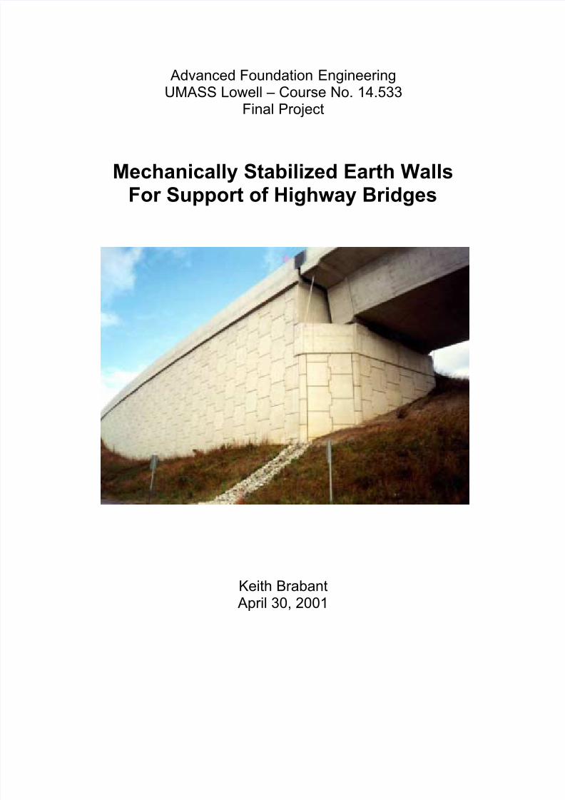
Mechanically Stabilized Earth WallsFor Support of Highway Bridges
Keith Brabant April 30, 2001
8/9/2019 Walls for Support of Highway Bridges _ Good
http://slidepdf.com/reader/full/walls-for-support-of-highway-bridges-good 2/28
Keith Brabant - Adv. Foundation Engineering - Final Project April 30, 2001
MSE Walls for Support of Highway Bridges 2
Table of Contents
Subject Page(s)
Abstract 3
Introduction 3
Basic Mechanism of Mechanically Stabilized Earth 3 - 4
Components of a MSE wall 4 - 9
Soil 5
Soil Reinforcement 6 - 7
Facing 8 - 9
Bridge Abutments and MSE walls 10 - 25
MSE Abutments
Benefits of MSE abutments 11
Performance of MSE abutments 11 -12
Settlement Performance 14 -15
Seismic Performance 15 - 16
Design Considerations 16 - 20Pile Supported Abutments 21 - 23
Integral Abutments 22 - 23
Design Considerations 22 - 23
Use of MSE and Mixed Abutments in the Northeast 23 - 24
Cost comparisons 24 - 25
Conclusions 25 - 26
Definitions 27
Bibliography 28
8/9/2019 Walls for Support of Highway Bridges _ Good
http://slidepdf.com/reader/full/walls-for-support-of-highway-bridges-good 3/28
8/9/2019 Walls for Support of Highway Bridges _ Good
http://slidepdf.com/reader/full/walls-for-support-of-highway-bridges-good 4/28
Keith Brabant - Adv. Foundation Engineering - Final Project April 30, 2001
MSE Walls for Support of Highway Bridges 4
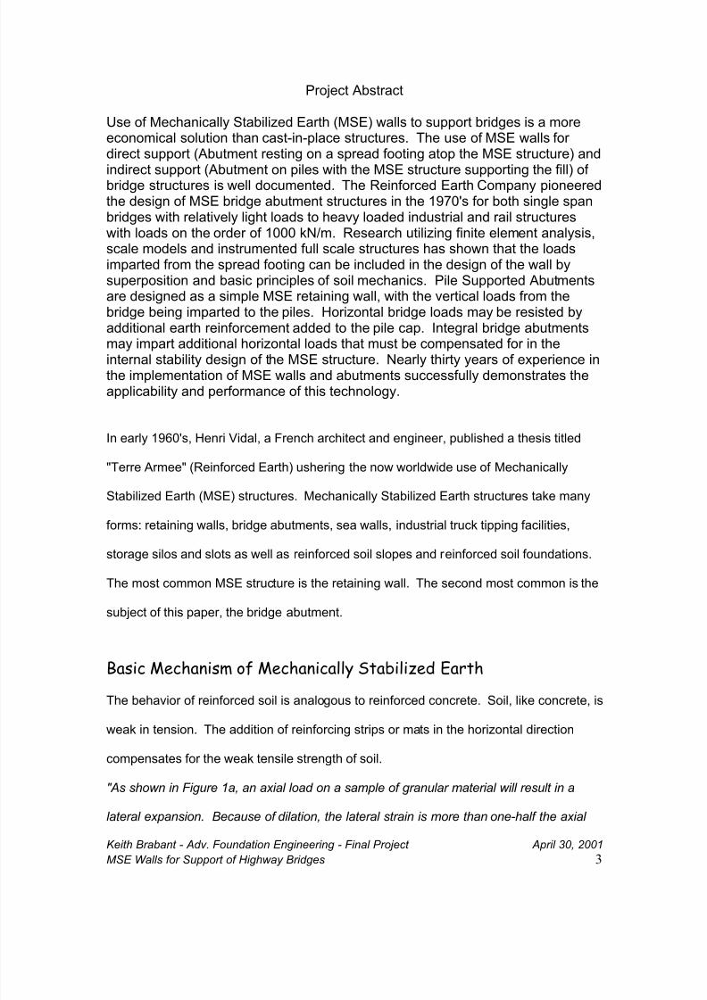
strain. However, if inextensible horizontal reinforcing elements are placed within the soil
mass, as shown in figure 1b, these reinforcements will prevent lateral strain because of
friction between the reinforcing elements and the soil, and the behavior will be as if a
lateral restraining force or load had been imposed on the element." 1
FIGURE 1 MECHANISM OF REINFORCED EARTH
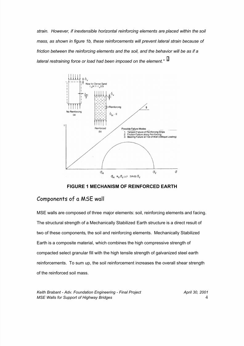
Components of a MSE wall
MSE walls are composed of three major elements: soil, reinforcing elements and facing.
The structural strength of a Mechanically Stabilized Earth structure is a direct result of
two of these components, the soil and reinforcing elements. Mechanically Stabilized
Earth is a composite material, which combines the high compressive strength of
compacted select granular fill with the high tensile strength of galvanized steel earth
reinforcements. To sum up, the soil reinforcement increases the overall shear strength
of the reinforced soil mass.
8/9/2019 Walls for Support of Highway Bridges _ Good
http://slidepdf.com/reader/full/walls-for-support-of-highway-bridges-good 5/28
Keith Brabant - Adv. Foundation Engineering - Final Project April 30, 2001
MSE Walls for Support of Highway Bridges 5
FIGURE 2 - COMPONENTS OF AN MSE WALL
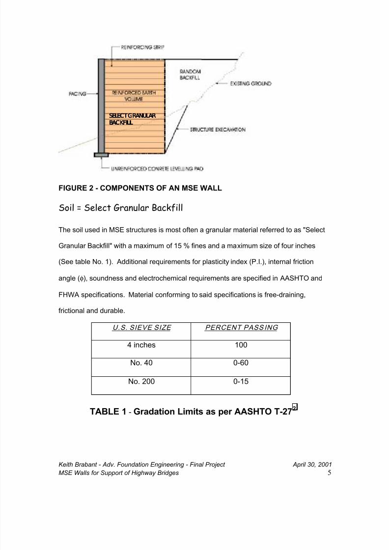
Soil = Select Granular Backfill
The soil used in MSE structures is most often a granular material referred to as "Select
Granular Backfill" with a maximum of 15 % fines and a maximum size of four inches
(See table No. 1). Additional requirements for plasticity index (P.I.), internal friction
angle (φ), soundness and electrochemical requirements are specified in AASHTO and
FHWA specifications. Material conforming to said specifications is free-draining,
frictional and durable.
U.S. SIEVE SIZE PERCENT PASS ING
4 inches 100
No. 40 0-60
No. 200 0-15
TABLE 1 - Gradation Limits as per AASHTO T-272
SELECT GRANULARSELECT GRANULARSELECT GRANULARSELECT GRANULAR
BACKFILLBACKFILLBACKFILLBACKFILL
8/9/2019 Walls for Support of Highway Bridges _ Good
http://slidepdf.com/reader/full/walls-for-support-of-highway-bridges-good 6/28
Keith Brabant - Adv. Foundation Engineering - Final Project April 30, 2001
MSE Walls for Support of Highway Bridges 6
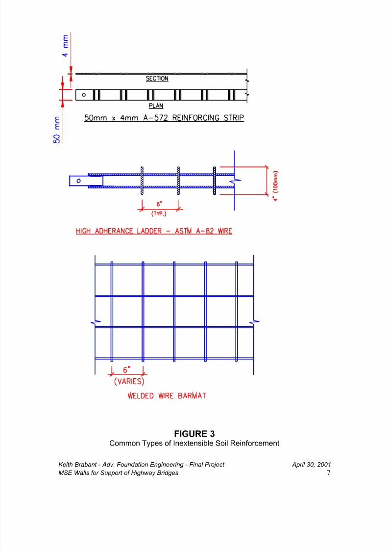
Soil Reinforcement
Soil Reinforcement is most often one of two types: inextensible (steel) or extensible
(plastic). Inextensible steel reinforcements come in three major categories, ribbed steel
strips, welded wire bar mats, and welded wire ladders. For permanent applications,
steel strips, ladders and bar-mats are galvanized. Strips are most often made of ASTM-
A572 grade 65 steel. Welded wire ladders and mats are often made of ASTM A82 wire.
Inextensible by definition means that the reinforcement does not stretch considerably.
Inextensible steel reinforcements are used in all mechanically stabilized earth
applications and are the most common soil reinforcement for critical structures such as
bridge abutments where control of deformation is crucial to the performance of the
bridge and substructure. 3 It should be noted that inextensible reinforcements have been
used successfully in MSE bridge abutment structures for over thirty years, while
research is still underway long trying to develop an extensible reinforcement that will
perform adequately in bridge applications.
Extensible geosynthetic reinforcements come in many different forms. The major types
include uniaxial and biaxial geogrids and woven and non-woven geotextiles. Extensible
reinforcements, by definition stretch, very often to the extent that the strain in the
reinforcement is greater than or equal to the strain in the soil mass, thus there is
considerable lateral movement when extensible soil reinforcements are used.
Extensible geosynthetics are often used such applications as reinforced slopes, basal
reinforcement and for wall applications such as temporary wire faced walls, wrapped
geotextile facing and blockwalls. All of the applications discussed in this paragraph are
applications where the deformation of the reinforcement and associated lateral structure
movements are tolerable.
8/9/2019 Walls for Support of Highway Bridges _ Good
http://slidepdf.com/reader/full/walls-for-support-of-highway-bridges-good 7/28
Keith Brabant - Adv. Foundation Engineering - Final Project April 30, 2001
MSE Walls for Support of Highway Bridges 7
FIGURE 3Common Types of Inextensible Soil Reinforcement
8/9/2019 Walls for Support of Highway Bridges _ Good
http://slidepdf.com/reader/full/walls-for-support-of-highway-bridges-good 8/28
8/9/2019 Walls for Support of Highway Bridges _ Good
http://slidepdf.com/reader/full/walls-for-support-of-highway-bridges-good 9/28
Keith Brabant - Adv. Foundation Engineering - Final Project April 30, 2001
MSE Walls for Support of Highway Bridges 9
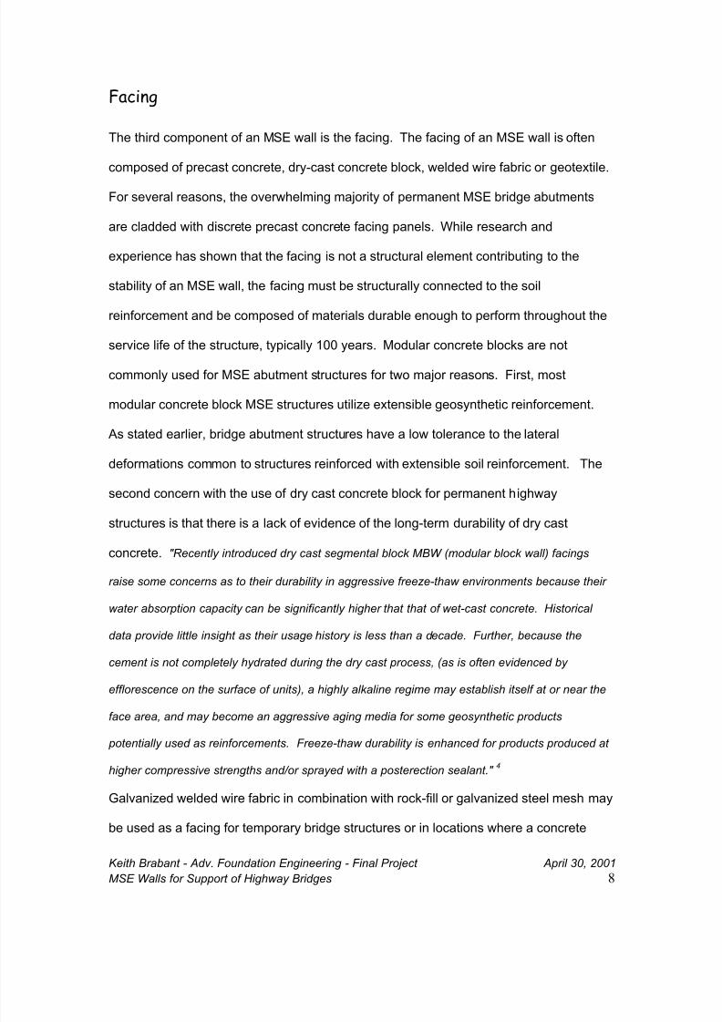
facing is not deemed feasible, such as in mining or forest roads. Geotextile wrapped
facing is not used in permanent applications due to vandalism concerns and the lack of
long-term durability of geotextiles exposed to direct sunlight. See Figure 4 for common
facing types used for MSE bridge abutments.
FIGURE 4 Precast Concrete Facings
8/9/2019 Walls for Support of Highway Bridges _ Good
http://slidepdf.com/reader/full/walls-for-support-of-highway-bridges-good 10/28
Keith Brabant - Adv. Foundation Engineering - Final Project April 30, 2001
MSE Walls for Support of Highway Bridges 10
Bridge Abutments
Early in the development of Reinforced Earth it became clear that bridge abutments
were an application where owners could reap the benefits of the performance and
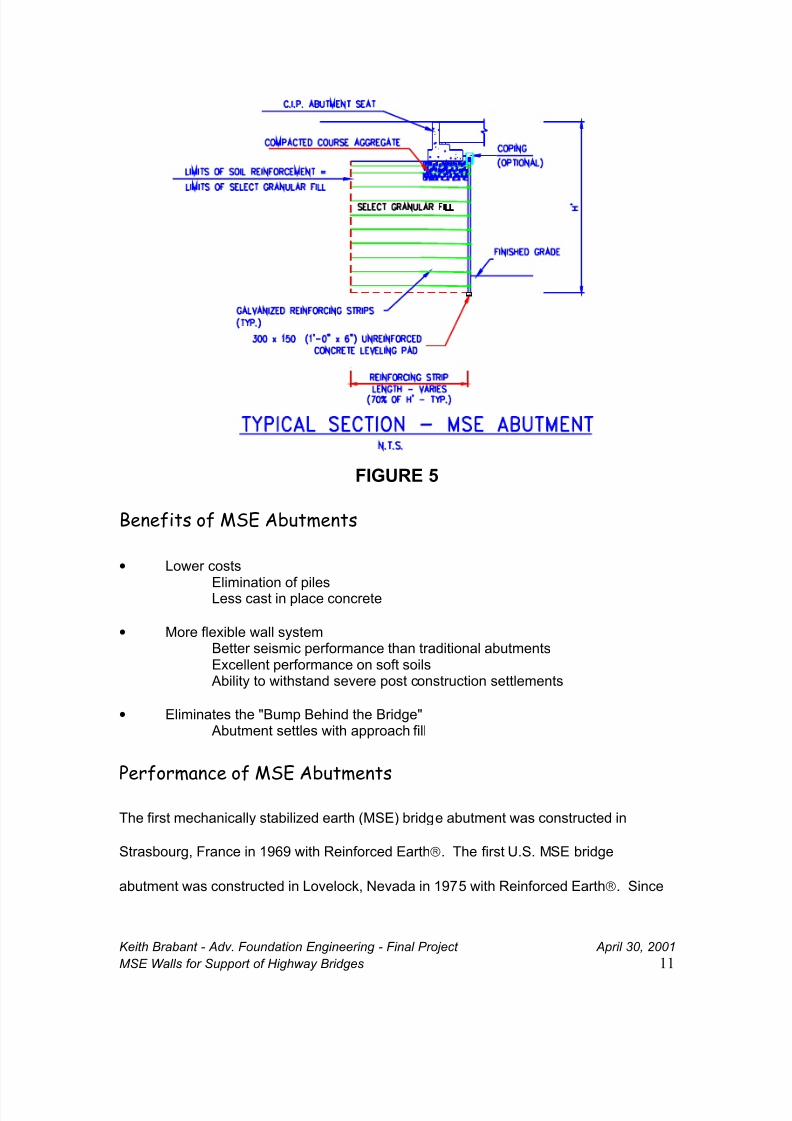
economy of mechanically stabilized earth structures. There are two types of bridge
abutments associated with mechanically stabilized earth walls. A "MSE Abutment" is
where the bridge beams are supported on spread footing, which is directly supported by
the MSE mass (See Figure 5). A "Mixed Abutment" is a pile supported abutment with
MSE walls providing support of the fill. (See Figure 7) Either type may be an "Integral"
abutment.
It is well established that bridge structures founded on spread footings can tolerate
vertical settlements on the order of two to four inches. 5 Tolerable horizontal movement
(angular distortion) typically ranges from 0.004 to 0.005 (ie. 0.4% to 0.5%). Thus,
horizontal movements of one to two inches can cause bridge girders to jam up against
backwalls, close expansion joints and damage bearings. 6 MSE walls reinforced with
inextensible reinforcements are proven to perform within the tolerable range of horizontal
movement. Unfortunately, the creep of extensible soil reinforcement leads to horizontal
deformations easily approaching and exceeding two inches for a typical size abutment
structure. One recent test project in Colorado utilizing geosynthetic reinforcement
displaced one inch in the first year since the beams were set. 7 Due to the time
dependent nature of creep in geosynthetics, time will tell how much displacement will
occur.
8/9/2019 Walls for Support of Highway Bridges _ Good
http://slidepdf.com/reader/full/walls-for-support-of-highway-bridges-good 11/28
Keith Brabant - Adv. Foundation Engineering - Final Project April 30, 2001
MSE Walls for Support of Highway Bridges 11
FIGURE 5
Benefits of MSE Abutments
• Lower costs
Elimination of pilesLess cast in place concrete
• More flexible wall systemBetter seismic performance than traditional abutmentsExcellent performance on soft soils
Ability to withstand severe post construction settlements
• Eliminates the "Bump Behind the Bridge" Abutment settles with approach fill
Performance of MSE Abutments
The first mechanically stabilized earth (MSE) bridge abutment was constructed in
Strasbourg, France in 1969 with Reinforced Earth. The first U.S. MSE bridge
abutment was constructed in Lovelock, Nevada in 1975 with Reinforced Earth. Since
8/9/2019 Walls for Support of Highway Bridges _ Good
http://slidepdf.com/reader/full/walls-for-support-of-highway-bridges-good 12/28
Keith Brabant - Adv. Foundation Engineering - Final Project April 30, 2001
MSE Walls for Support of Highway Bridges 12
1975, over 220 MSE abutments have been constructed in the United States with
Reinforced Earth technology. Other companies such as VSL and the Neel Co. have
also constructed MSE abutments. MSE abutments are approved for use by 20 state
DOT's. In the northeast region, over 100 MSE abutments have been constructed in
Connecticut, Maine, Massachusetts, New Hampshire, New York and Vermont. New
York State DOT (NYSDOT) has been a leader in the use of MSE abutments among
state highway agencies. Since 1977, over 80 MSE abutments have been constructed
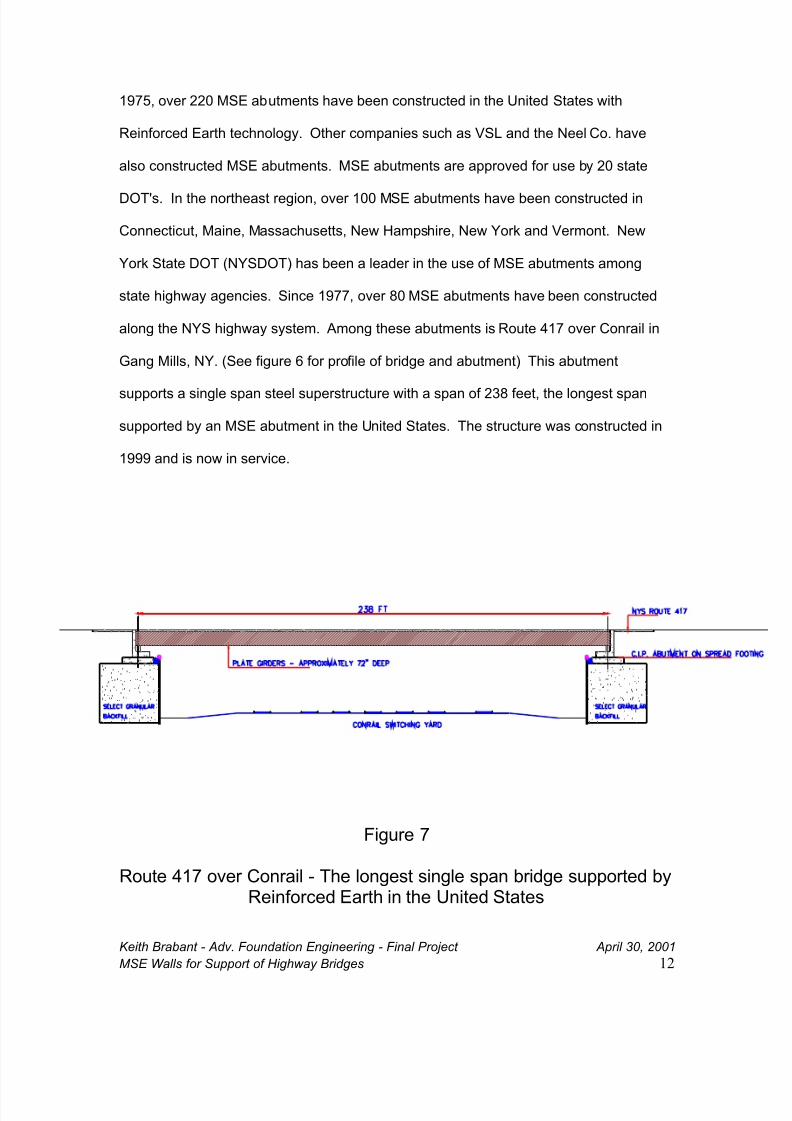
along the NYS highway system. Among these abutments is Route 417 over Conrail in
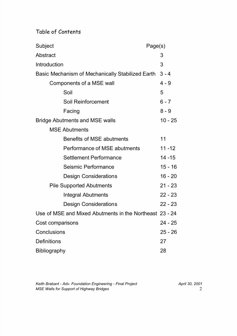
Gang Mills, NY. (See figure 6 for profile of bridge and abutment) This abutment
supports a single span steel superstructure with a span of 238 feet, the longest span
supported by an MSE abutment in the United States. The structure was constructed in
1999 and is now in service.
Figure 7
Route 417 over Conrail - The longest single span bridge supported byReinforced Earth in the United States
8/9/2019 Walls for Support of Highway Bridges _ Good
http://slidepdf.com/reader/full/walls-for-support-of-highway-bridges-good 13/28
Keith Brabant - Adv. Foundation Engineering - Final Project April 30, 2001
MSE Walls for Support of Highway Bridges 13
Settlement Performance
Studies have shown that bridge abutments founded on medium-dense granular soils
(typical of a mse structure) will tolerate post deck construction settlements on the order
of 2 to 4 inches. Typically, a maximum 1/4" of settlement can be expected of granular fill
after construction of the deck. 8 Experience has shown that settlement greater than six
inches can be accommodated with special details and jacking the superstructure. 9
Thus, for the case of MSE abutments, the settlement of the select granular backfill will
be on the order of 1/4". It is the settlement of the foundation soils that need to be
essentially complete prior to construction of the bridge deck.
The ability of MSE abutments to withstand even extreme settlements is another benefit
of this extremely flexible construction technology. Total settlements over 3 feet and
differential settlements on the order of 1 ft in 100 ft have been accommodated by MSE
walls prior to the construction of spread footings for bridge abutments. The ability of
MSE walls to endure extreme total settlements allows for MSE abutments to be
constructed in locations were even pile supported abutments may be infeasible. Such
applications are where the settlement of deep deposits of soft soils would create
excessive down-drag forces on piles.
Early applications of MSE abutments in extreme cases of extreme settlement include a
103 ft single span bridge carrying US Route 1 over the Boston & Maine Railroad,
constructed in 1980 in Wells, Maine. Significant settlement, up to twenty-five (25")
inches at the abutment locations, was expected due to over 150 feet of layers of loose to
medium sands and clay. Reinforced Earth walls were selected at bid time as the most
economical alternate. The single span bridge, abutments and retaining walls cost
$725,000, a 32% cost savings of a three span pile supported structure, estimated at
8/9/2019 Walls for Support of Highway Bridges _ Good
http://slidepdf.com/reader/full/walls-for-support-of-highway-bridges-good 14/28
Keith Brabant - Adv. Foundation Engineering - Final Project April 30, 2001
MSE Walls for Support of Highway Bridges 14
$1,060,000. The approach embankments and Reinforced Earth retaining walls were
constructed and preloaded prior to construction of the bridge abutment seats. Eight and
one half inches of settlement occurred prior to construction of the bridge. After removing
the preload and constructing the abutment seat and bridge, an additional six and one-
half inches of settlement occurred within the first two years of service. Approximately
twelve additional inches of settlement was expected over the next ten years. Provisions
were made in the design and construction of the bridge and substructure to allow for
jacks to raise the bridge to maintain the design profile elevations. Most importantly,
gages to monitor lateral movement were installed, and essentially no lateral movement
of the wall panels has been measured. 10
Another example of extreme settlements of MSE abutments in the northeast: a
Reinforced Earth Abutment for a railroad unloading trestle in Burlington, Vermont was
expected to settle approximately six inches. The actual settlement exceeded sixteen
inches prior to the construction of the abutment seats. The contractor was able to adjust
the elevations of the bridge pedestal to compensate for the settlement. A now common
solution for foundation improvement is to utilize a permanent MSE wall as a preload prior
to the construction of the bridge and substructure.
It is clear that MSE abutment structures can withstand extreme total settlements,
another benefit is the capacity to withstand differential settlements. The use of discrete
facing elements typically allows for a differential settlement of one percent (1 ft in 100 ft
of wall facing). If differential settlement is expected to be greater than one percent, slip
joints may be added to the wall and/or foundation improvements such as dynamic
compaction, replacement of unsuitable materials and/or preloading may be performed
prior to the construction of the MSE wall.
8/9/2019 Walls for Support of Highway Bridges _ Good
http://slidepdf.com/reader/full/walls-for-support-of-highway-bridges-good 15/28
Keith Brabant - Adv. Foundation Engineering - Final Project April 30, 2001
MSE Walls for Support of Highway Bridges 15
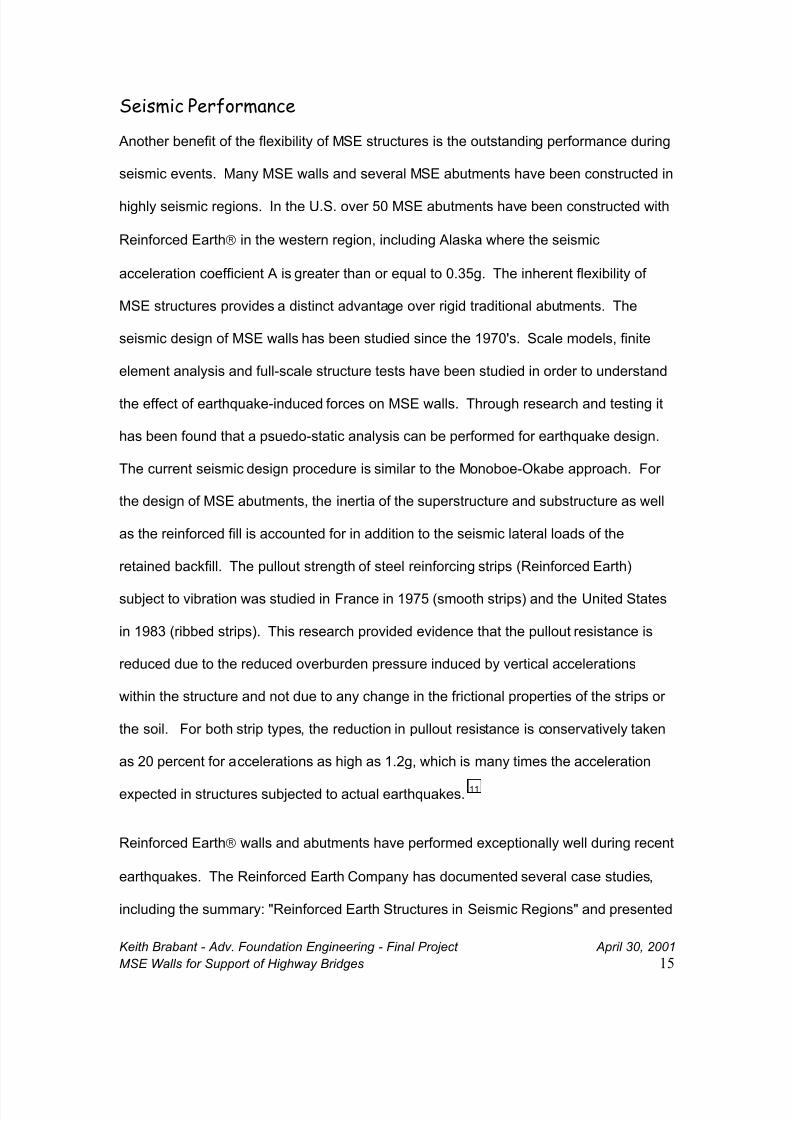
Seismic Performance
Another benefit of the flexibility of MSE structures is the outstanding performance during
seismic events. Many MSE walls and several MSE abutments have been constructed in
highly seismic regions. In the U.S. over 50 MSE abutments have been constructed with
Reinforced Earth in the western region, including Alaska where the seismic
acceleration coefficient A is greater than or equal to 0.35g. The inherent flexibility of
MSE structures provides a distinct advantage over rigid traditional abutments. The
seismic design of MSE walls has been studied since the 1970's. Scale models, finite
element analysis and full-scale structure tests have been studied in order to understand
the effect of earthquake-induced forces on MSE walls. Through research and testing it
has been found that a psuedo-static analysis can be performed for earthquake design.
The current seismic design procedure is similar to the Monoboe-Okabe approach. For
the design of MSE abutments, the inertia of the superstructure and substructure as well
as the reinforced fill is accounted for in addition to the seismic lateral loads of the
retained backfill. The pullout strength of steel reinforcing strips (Reinforced Earth)
subject to vibration was studied in France in 1975 (smooth strips) and the United States
in 1983 (ribbed strips). This research provided evidence that the pullout resistance is
reduced due to the reduced overburden pressure induced by vertical accelerations
within the structure and not due to any change in the frictional properties of the strips or
the soil. For both strip types, the reduction in pullout resistance is conservatively taken
as 20 percent for accelerations as high as 1.2g, which is many times the acceleration
expected in structures subjected to actual earthquakes. 11
Reinforced Earth walls and abutments have performed exceptionally well during recent
earthquakes. The Reinforced Earth Company has documented several case studies,
including the summary: "Reinforced Earth Structures in Seismic Regions" and presented
8/9/2019 Walls for Support of Highway Bridges _ Good
http://slidepdf.com/reader/full/walls-for-support-of-highway-bridges-good 16/28
Keith Brabant - Adv. Foundation Engineering - Final Project April 30, 2001
MSE Walls for Support of Highway Bridges 16
technical papers at the International Symposium on Earth Reinforcement. A short list of
case studies follows:
• Liege, Belgium, 1983. Three abutments and several high retaining walls(up to 17m) were within 3.5 km of the epicenter of a Richter Magnitude
5.0 earthquake. None of these structures showed any damage ordeformation.
• Bay of Plenty, New Zealand, 1987. Two Reinforced Earth abutmentswere nearing completion in Maniatutu, 30km from the epicenter of aRichter magnitude 6.3 earthquake. The structures performed perfectlyduring the earthquake and construction was completed with no remedialaction required.
• Northridge, California, 1994. Twenty-one Reinforced Earth Walls and twoReinforced Earth bridge abutments were subjected to this Richtermagnitude 6.7 earthquake in the densely populated San Fernando Valley,
20 miles northwest of downtown Los Angeles. Sever damage occurred tobuildings, bridges, and freeways. All of the Reinforced Earth Structuresperformed extremely well, with only superficial damage to a few facingpanels of one wall.
Design of MSE Abutments
The design of a MSE abutment is similar to that of a conventional MSE wall. The effects
of the bridge and abutment loads are super-imposed onto the soil loads. Research
including finite element analysis, scale models and full-scale instrumented structures has
led to the development of a design method that is both conservative and predictable.
In 1973 a full-scale load test of a Reinforced Earth MSE abutment was conducted by the
French Road Research Laboratory (Lille, France). A 5.6 m high by 15 m long
Reinforced Earth structure supported a spread footing which supported a bridge
structure consisting of a 19 m span with a c.i.p. slab. Strain gages were attached to the
earth reinforcements to measure the tensile stresses during all phases of construction
and service. The study confirmed the theoretical basis of mse abutment design. 12
From this and other studies, the decrease in the earth pressure coefficient, K, with depth
was confirmed. In addition, the location and distribution of tensile stresses in the earth
8/9/2019 Walls for Support of Highway Bridges _ Good
http://slidepdf.com/reader/full/walls-for-support-of-highway-bridges-good 17/28
Keith Brabant - Adv. Foundation Engineering - Final Project April 30, 2001
MSE Walls for Support of Highway Bridges 17
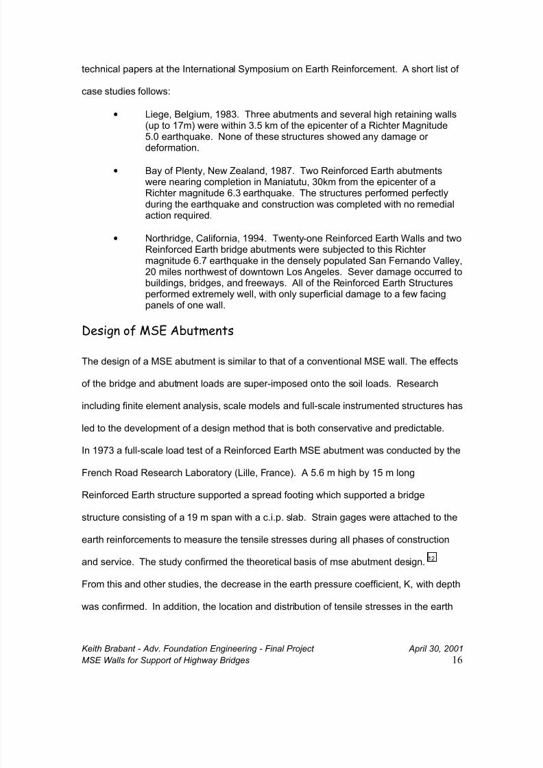
reinforcements was verified. Further studies have confirmed the state of stress and
location of maximum tension for MSE Abutment structures. 13
FIGURE 8 14
In the design of a MSE abutment, the vertical loads from the bridge are transmitted from
the abutment seat along a 2 V to 1 H distribution to the bottom of the wall. Horizontal
loads from the bridge are distributed along a Rankine plane of 45° + φ/2. The "active
zone" of the MSE structure may be affected by the geometry of the abutment seat. The
pullout safety of the reinforcing elements is determined by dividing the total resisting
force (via friction of the reinforcing elements and soil) by the total driving force (the
tension in the reinforcing elements created by the soil and bridge loads). The maximum
stress in the reinforcing elements is also checked to be sure it is less than the allowable
stress of the reinforcing elements at the end of the service life, typically 100 years. It
should be noted that the service life calculations for galvanized steel reinforcements are
very conservative. Research is now underway by several state DOT's including Florida
and New York, and preliminary findings show that the corrosion rates, as recommended
by AASHTO, are nearly twice what is being found through tests of retrieving buried
8/9/2019 Walls for Support of Highway Bridges _ Good
http://slidepdf.com/reader/full/walls-for-support-of-highway-bridges-good 18/28
Keith Brabant - Adv. Foundation Engineering - Final Project April 30, 2001
MSE Walls for Support of Highway Bridges 18
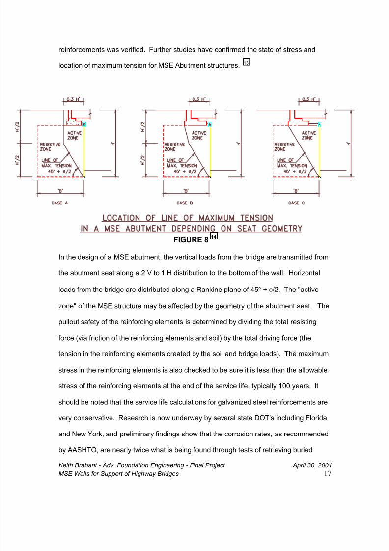
reinforcements that have been buried for over 15 to 20 years. 15 Thus there is a hidden
safety factor being imposed over and above the safety factors already used in design.
FIGURE 9 - Horizontal Free Body Diagram
Psupp = Supplemental Horizontal load from bridge. Ps = Surcharge
P = Earth Pressure Pae = Seismic Earth Pressure
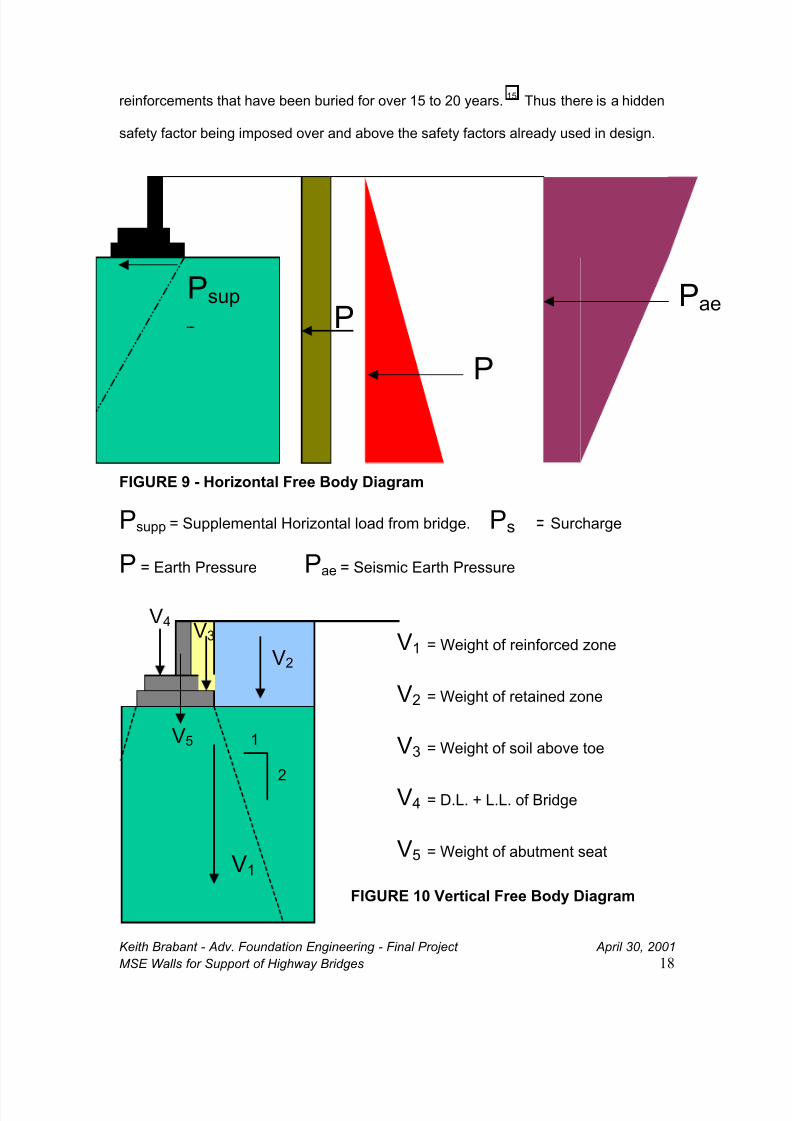
V1 = Weight of reinforced zone
V2 = Weight of retained zone
V3 = Weight of soil above toe
V4 = D.L. + L.L. of Bridge
V5 = Weight of abutment seat
FIGURE 10 Vertical Free Body Diagram
V1
2
V2
V4
V5
V3
1
Pae
P
PPsup
8/9/2019 Walls for Support of Highway Bridges _ Good
http://slidepdf.com/reader/full/walls-for-support-of-highway-bridges-good 19/28
Keith Brabant - Adv. Foundation Engineering - Final Project April 30, 2001
MSE Walls for Support of Highway Bridges 19
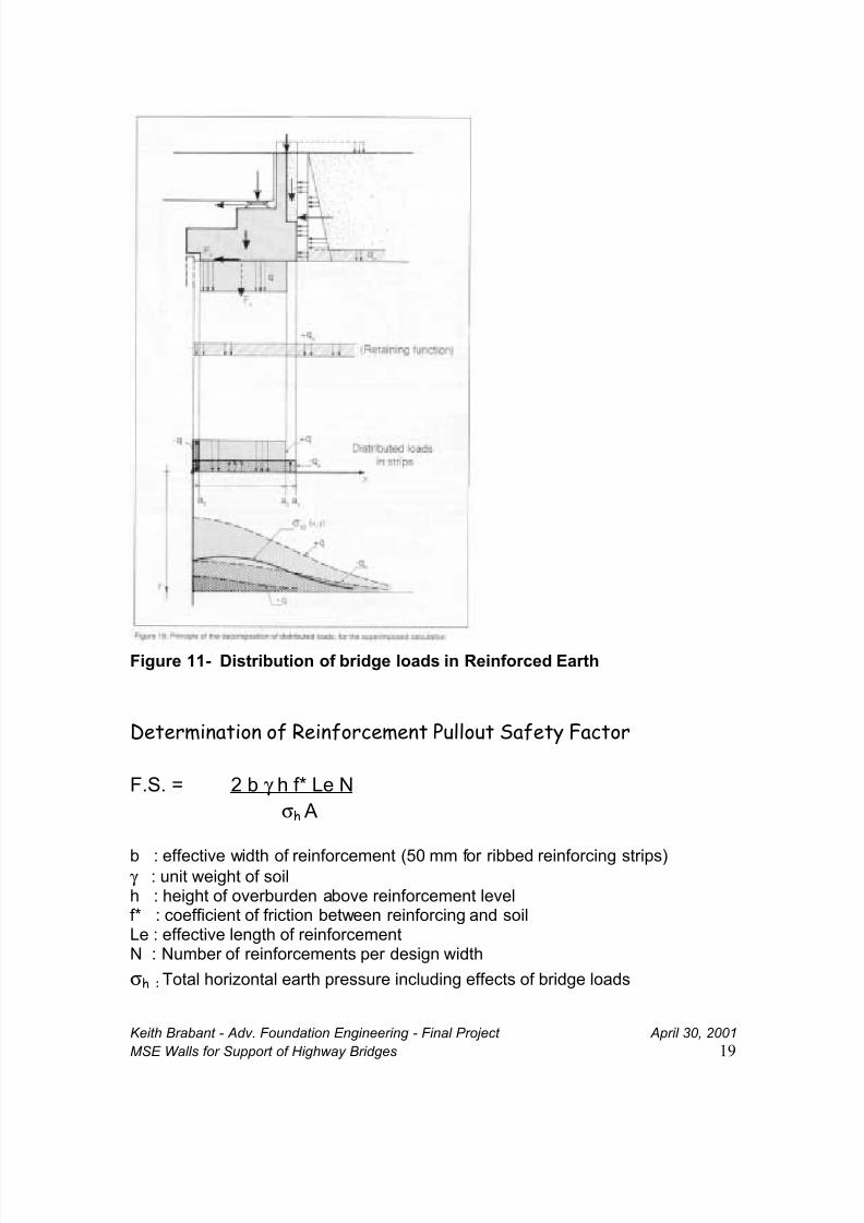
Figure 11- Distribution of bridge loads in Reinforced Earth
Determination of Reinforcement Pullout Safety Factor
F.S. = 2 b γ h f* Le N
σh A
b : effective width of reinforcement (50 mm for ribbed reinforcing strips)γ : unit weight of soilh : height of overburden above reinforcement levelf* : coefficient of friction between reinforcing and soilLe : effective length of reinforcementN : Number of reinforcements per design width
σh : Total horizontal earth pressure including effects of bridge loads
8/9/2019 Walls for Support of Highway Bridges _ Good
http://slidepdf.com/reader/full/walls-for-support-of-highway-bridges-good 20/28
Keith Brabant - Adv. Foundation Engineering - Final Project April 30, 2001
MSE Walls for Support of Highway Bridges 20
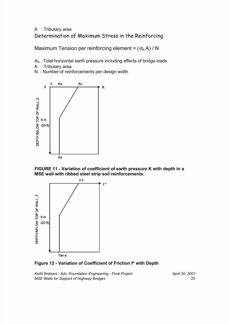
A : Tributary area
Determination of Maximum Stress in the Reinforcing
Maximum Tension per reinforcing element = (σh A) / N
σh : Total horizontal earth pressure including effects of bridge loads
A : Tributary areaN : Number of reinforcements per design width
FIGURE 11 - Variation of coefficient of earth pressure K with depth in aMSE wall with ribbed steel strip soil reinforcements.
Figure 12 - Variation of Coefficient of Friction f* with Depth
00
Ka Ko
6 m
(20 ft)
Ka
K
D E P T H B E L O W T
O P O
F W A L L , Z
00
Ka Ko
6 m
(20 ft)
Ka
K
D E P T H B E L O W T
O P O
F W A L L , Z
2.0
6 m
(20 ft)
Tan φ
f *
D E P T H B E L
O W T
O P O F W A L L , Z
2.0
6 m
(20 ft)
Tan φ
f *
D E P T H B E L
O W T
O P O F W A L L , Z
8/9/2019 Walls for Support of Highway Bridges _ Good
http://slidepdf.com/reader/full/walls-for-support-of-highway-bridges-good 21/28
Keith Brabant - Adv. Foundation Engineering - Final Project April 30, 2001
MSE Walls for Support of Highway Bridges 21
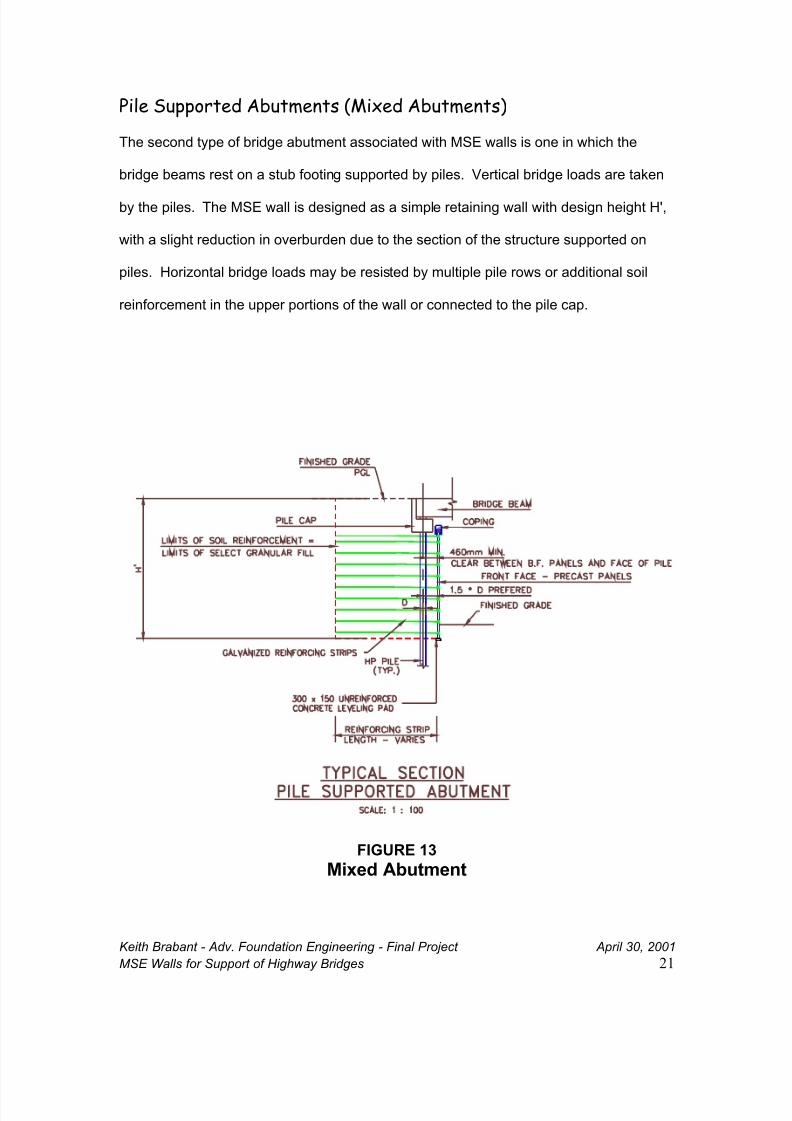
Pile Supported Abutments (Mixed Abutments)
The second type of bridge abutment associated with MSE walls is one in which the
bridge beams rest on a stub footing supported by piles. Vertical bridge loads are taken
by the piles. The MSE wall is designed as a simple retaining wall with design height H',
with a slight reduction in overburden due to the section of the structure supported on
piles. Horizontal bridge loads may be resisted by multiple pile rows or additional soil
reinforcement in the upper portions of the wall or connected to the pile cap.
FIGURE 13
Mixed Abutment
8/9/2019 Walls for Support of Highway Bridges _ Good
http://slidepdf.com/reader/full/walls-for-support-of-highway-bridges-good 22/28
Keith Brabant - Adv. Foundation Engineering - Final Project April 30, 2001
MSE Walls for Support of Highway Bridges 22
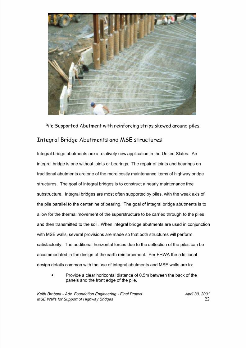
Pile Supported Abutment with reinforcing strips skewed around piles.
Integral Bridge Abutments and MSE structures
Integral bridge abutments are a relatively new application in the United States. An
integral bridge is one without joints or bearings. The repair of joints and bearings on
traditional abutments are one of the more costly maintenance items of highway bridge
structures. The goal of integral bridges is to construct a nearly maintenance free
substructure. Integral bridges are most often supported by piles, with the weak axis of
the pile parallel to the centerline of bearing. The goal of integral bridge abutments is to
allow for the thermal movement of the superstructure to be carried through to the piles
and then transmitted to the soil. When integral bridge abutments are used in conjunction
with MSE walls, several provisions are made so that both structures will perform
satisfactorily. The additional horizontal forces due to the deflection of the piles can be
accommodated in the design of the earth reinforcement. Per FHWA the additional
design details common with the use of integral abutments and MSE walls are to:
• Provide a clear horizontal distance of 0.5m between the back of thepanels and the front edge of the pile.
8/9/2019 Walls for Support of Highway Bridges _ Good
http://slidepdf.com/reader/full/walls-for-support-of-highway-bridges-good 23/28
Keith Brabant - Adv. Foundation Engineering - Final Project April 30, 2001
MSE Walls for Support of Highway Bridges 23
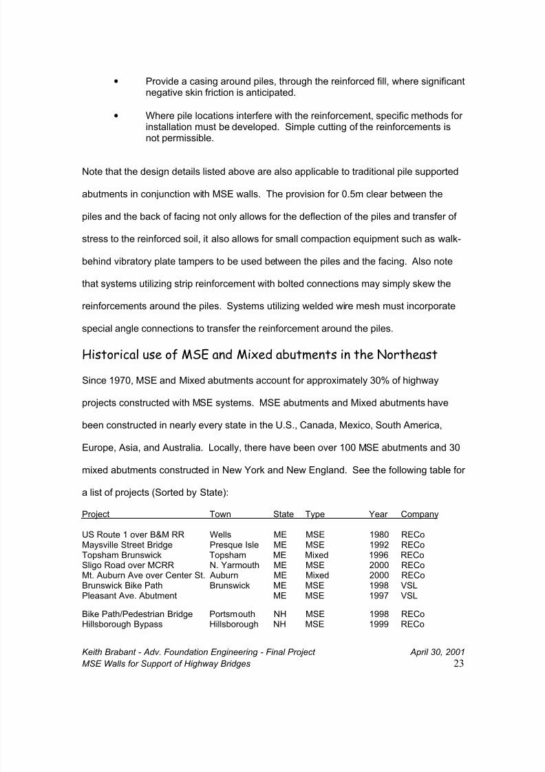
• Provide a casing around piles, through the reinforced fill, where significantnegative skin friction is anticipated.
• Where pile locations interfere with the reinforcement, specific methods forinstallation must be developed. Simple cutting of the reinforcements is
not permissible.
Note that the design details listed above are also applicable to traditional pile supported
abutments in conjunction with MSE walls. The provision for 0.5m clear between the
piles and the back of facing not only allows for the deflection of the piles and transfer of
stress to the reinforced soil, it also allows for small compaction equipment such as walk-
behind vibratory plate tampers to be used between the piles and the facing. Also note
that systems utilizing strip reinforcement with bolted connections may simply skew the
reinforcements around the piles. Systems utilizing welded wire mesh must incorporate
special angle connections to transfer the reinforcement around the piles.
Historical use of MSE and Mixed abutments in the Northeast
Since 1970, MSE and Mixed abutments account for approximately 30% of highway
projects constructed with MSE systems. MSE abutments and Mixed abutments have
been constructed in nearly every state in the U.S., Canada, Mexico, South America,
Europe, Asia, and Australia. Locally, there have been over 100 MSE abutments and 30
mixed abutments constructed in New York and New England. See the following table for
a list of projects (Sorted by State):
Project Town State Type Year Company
US Route 1 over B&M RR Wells ME MSE 1980 RECoMaysville Street Bridge Presque Isle ME MSE 1992 RECoTopsham Brunswick Topsham ME Mixed 1996 RECoSligo Road over MCRR N. Yarmouth ME MSE 2000 RECoMt. Auburn Ave over Center St. Auburn ME Mixed 2000 RECoBrunswick Bike Path Brunswick ME MSE 1998 VSLPleasant Ave. Abutment ME MSE 1997 VSL
Bike Path/Pedestrian Bridge Portsmouth NH MSE 1998 RECoHillsborough Bypass Hillsborough NH MSE 1999 RECo
8/9/2019 Walls for Support of Highway Bridges _ Good
http://slidepdf.com/reader/full/walls-for-support-of-highway-bridges-good 24/28
Keith Brabant - Adv. Foundation Engineering - Final Project April 30, 2001
MSE Walls for Support of Highway Bridges 24
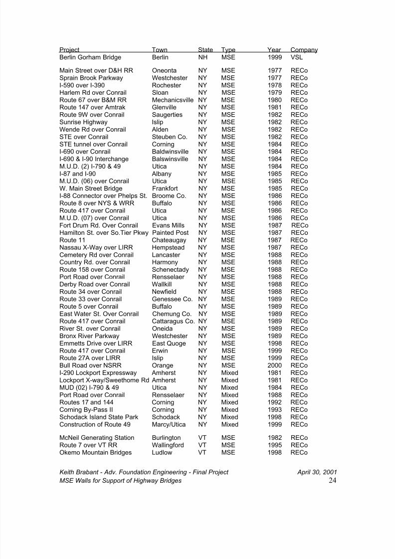
Project Town State Type Year CompanyBerlin Gorham Bridge Berlin NH MSE 1999 VSL
Main Street over D&H RR Oneonta NY MSE 1977 RECoSprain Brook Parkway Westchester NY MSE 1977 RECoI-590 over I-390 Rochester NY MSE 1978 RECoHarlem Rd over Conrail Sloan NY MSE 1979 RECo
Route 67 over B&M RR Mechanicsville NY MSE 1980 RECoRoute 147 over Amtrak Glenville NY MSE 1981 RECoRoute 9W over Conrail Saugerties NY MSE 1982 RECoSunrise Highway Islip NY MSE 1982 RECoWende Rd over Conrail Alden NY MSE 1982 RECoSTE over Conrail Steuben Co. NY MSE 1982 RECoSTE tunnel over Conrail Corning NY MSE 1984 RECoI-690 over Conrail Baldwinsville NY MSE 1984 RECoI-690 & I-90 Interchange Balswinsville NY MSE 1984 RECoM.U.D. (2) I-790 & 49 Utica NY MSE 1984 RECoI-87 and I-90 Albany NY MSE 1985 RECoM.U.D. (06) over Conrail Utica NY MSE 1985 RECoW. Main Street Bridge Frankfort NY MSE 1985 RECo
I-88 Connector over Phelps St. Broome Co. NY MSE 1986 RECoRoute 8 over NYS & WRR Buffalo NY MSE 1986 RECoRoute 417 over Conrail Utica NY MSE 1986 RECoM.U.D. (07) over Conrail Utica NY MSE 1986 RECoFort Drum Rd. Over Conrail Evans Mills NY MSE 1987 RECoHamilton St. over So.Tier Pkwy Painted Post NY MSE 1987 RECoRoute 11 Chateaugay NY MSE 1987 RECoNassau X-Way over LIRR Hempstead NY MSE 1987 RECoCemetery Rd over Conrail Lancaster NY MSE 1988 RECoCountry Rd. over Conrail Harmony NY MSE 1988 RECoRoute 158 over Conrail Schenectady NY MSE 1988 RECoPort Road over Conrail Rensselaer NY MSE 1988 RECoDerby Road over Conrail Wallkill NY MSE 1988 RECo
Route 34 over Conrail Newfield NY MSE 1988 RECoRoute 33 over Conrail Genessee Co. NY MSE 1989 RECoRoute 5 over Conrail Buffalo NY MSE 1989 RECoEast Water St. Over Conrail Chemung Co. NY MSE 1989 RECoRoute 417 over Conrail Cattaragus Co. NY MSE 1989 RECoRiver St. over Conrail Oneida NY MSE 1989 RECoBronx River Parkway Westchester NY MSE 1989 RECoEmmetts Drive over LIRR East Quoge NY MSE 1998 RECoRoute 417 over Conrail Erwin NY MSE 1999 RECoRoute 27A over LIRR Islip NY MSE 1999 RECoBull Road over NSRR Orange NY MSE 2000 RECoI-290 Lockport Expressway Amherst NY Mixed 1981 RECoLockport X-way/Sweethome Rd Amherst NY Mixed 1981 RECoMUD (02) I-790 & 49 Utica NY Mixed 1984 RECoPort Road over Conrail Rensselaer NY Mixed 1988 RECoRoutes 17 and 144 Corning NY Mixed 1992 RECoCorning By-Pass II Corning NY Mixed 1993 RECoSchodack Island State Park Schodack NY Mixed 1998 RECoConstruction of Route 49 Marcy/Utica NY Mixed 1999 RECo
McNeil Generating Station Burlington VT MSE 1982 RECoRoute 7 over VT RR Wallingford VT MSE 1995 RECoOkemo Mountain Bridges Ludlow VT MSE 1998 RECo
8/9/2019 Walls for Support of Highway Bridges _ Good
http://slidepdf.com/reader/full/walls-for-support-of-highway-bridges-good 25/28
Keith Brabant - Adv. Foundation Engineering - Final Project April 30, 2001
MSE Walls for Support of Highway Bridges 25
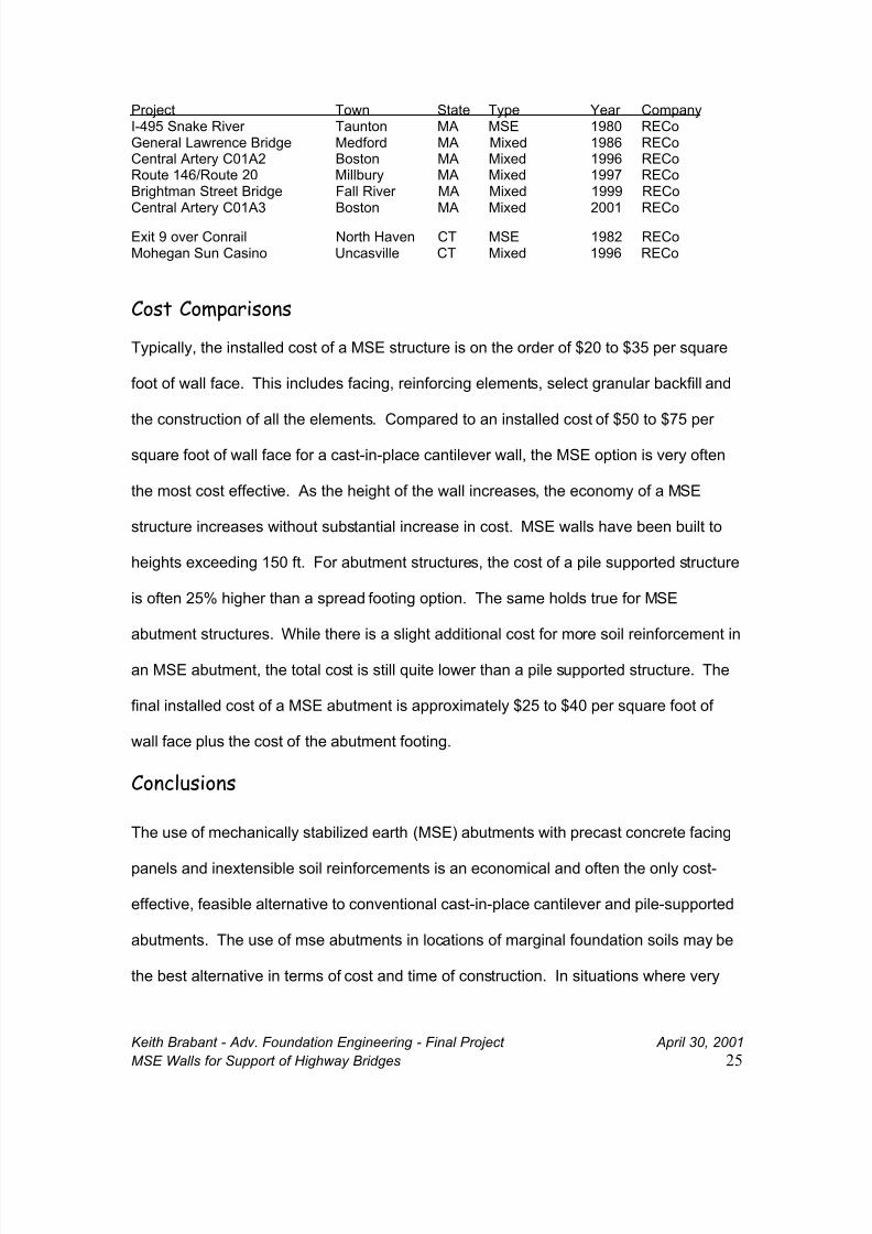
Project Town State Type Year CompanyI-495 Snake River Taunton MA MSE 1980 RECoGeneral Lawrence Bridge Medford MA Mixed 1986 RECoCentral Artery C01A2 Boston MA Mixed 1996 RECoRoute 146/Route 20 Millbury MA Mixed 1997 RECoBrightman Street Bridge Fall River MA Mixed 1999 RECoCentral Artery C01A3 Boston MA Mixed 2001 RECo
Exit 9 over Conrail North Haven CT MSE 1982 RECoMohegan Sun Casino Uncasville CT Mixed 1996 RECo
Cost Comparisons
Typically, the installed cost of a MSE structure is on the order of $20 to $35 per square
foot of wall face. This includes facing, reinforcing elements, select granular backfill and
the construction of all the elements. Compared to an installed cost of $50 to $75 per
square foot of wall face for a cast-in-place cantilever wall, the MSE option is very often
the most cost effective. As the height of the wall increases, the economy of a MSE
structure increases without substantial increase in cost. MSE walls have been built to
heights exceeding 150 ft. For abutment structures, the cost of a pile supported structure
is often 25% higher than a spread footing option. The same holds true for MSE
abutment structures. While there is a slight additional cost for more soil reinforcement in
an MSE abutment, the total cost is still quite lower than a pile supported structure. The
final installed cost of a MSE abutment is approximately $25 to $40 per square foot of
wall face plus the cost of the abutment footing.
Conclusions
The use of mechanically stabilized earth (MSE) abutments with precast concrete facing
panels and inextensible soil reinforcements is an economical and often the only cost-
effective, feasible alternative to conventional cast-in-place cantilever and pile-supported
abutments. The use of mse abutments in locations of marginal foundation soils may be
the best alternative in terms of cost and time of construction. In situations where very
8/9/2019 Walls for Support of Highway Bridges _ Good
http://slidepdf.com/reader/full/walls-for-support-of-highway-bridges-good 26/28
Keith Brabant - Adv. Foundation Engineering - Final Project April 30, 2001
MSE Walls for Support of Highway Bridges 26
soft soils underlay the embankment and bridge abutment, mse abutments may be used
in conjunction with preloads or other methods of foundation improvement in lieu of a pile
supported abutment structure. Mixed abutments may be used when differential
settlement between the abutments due to varying soil conditions would pose undo
stresses on the superstructure. Mixed abutments may also be used when significant
settlements are expected and in integral bridge abutments.
The seismic performance of mse walls and abutments is proven. Worldwide experience
in nearly all of the major earthquakes of the last thirty years has provided ample data on
the structural stability of MSE structures during seismic loading.
The design methods for mse walls, abutments and mixed abutments are fairly simple
and straightforward. Over thirty years of research and experience has combined to
develop a design method in which the effects of the bridge and earth loads are easily
calculated.
The use of inextensible reinforcements with precast concrete facing panels in bridge
applications is proven and reliable. Much more research and development must occur
before extensible reinforcements can perform to the level of inextensible reinforcements
in bridge applications. The performance of dry-cast concrete block must be improved in
freeze thaw situations in order for block walls to be applicable to highway structures.
The economy of MSE walls and abutments is one of the major reasons that the
technology has become the standard for retaining walls built in fill situations. Along the
way, the performance of MSE walls and abutments on marginal foundations has made it
the engineered solution to difficult foundation problems.
8/9/2019 Walls for Support of Highway Bridges _ Good
http://slidepdf.com/reader/full/walls-for-support-of-highway-bridges-good 27/28
Keith Brabant - Adv. Foundation Engineering - Final Project April 30, 2001
MSE Walls for Support of Highway Bridges 27
Definitions
MSE Abutment - A bridge structure founded on a spread footing supportedby a reinforced soil retaining structure
Mixed Abutment- A bridge structure founded on a footing on piles with areinforced soil retaining structure providing earth retentiononly.
Integral Bridge Abutment - A structure in which there are no joints between the beamsand abutment. Thermal stresses of the superstructurecause deflection of the abutment and pile foundation.
Select granular backfill- Backfill material meeting specifications including frictionangle, gradation, soundness, salt content and plasticity.
Facing- A component of a reinforced soil system used to prevent
the soil from raveling out between rows of reinforcement.For bridge abutment structures, the facing is almost alwaysprecast concrete panels.
Mechanically Stabilized Earth (MSE)
A generic term that includes reinforced soil (a term usedwhen multiple layers of inclusions act as reinforcement insoils placed as fill)
Reinforced Earth A registered Trademark of The Reinforced EarthCompany. Reinforced Earth is the one of the most widely
used and researched of any proprietary mse wall systems.
Extensible- "To stretch". The deformation of the reinforcement atfailure is comparable or greater than the deformabilityof soil. Geosynthetic materials (for example:polyester, polyetheline and pvc) are extensible.
Inextensible- The opposite of extensible. The deformation of thereinforcement at failure is much less than thedeformability of soil. Most steel reinforcements (forexample: strips, ladders and bar mats) are
inextensible.
Dilation - The phenomenon in which dense granular soil particlesexpand during shear, typical of soils less than 20 feetdeep.
8/9/2019 Walls for Support of Highway Bridges _ Good
http://slidepdf.com/reader/full/walls-for-support-of-highway-bridges-good 28/28
Bibliography
1. McKittrick, D.P. (1978) "Reinforced Earth: Application of theory andresearch to practice." Synopsium on soil reinforcing and stabilizingtechniques. New South Wales Institute of Technology. October
16, 1978.
2., 3 & 4 FHWA. (1999). "Mechanically stabilized earth walls and reinforcedsoil slopes - design and construction guidelines." FHWA Demo.Project 82. USDOT, FHWA June 1999.
5. Sargand, S.M. (1999) "Spread footing foundation for highwaybridge applications." Journal of Geotechnical andGeoenvironmental Engineering. 125 (5). 373-382
6. The Reinforced Earth Company, Internal Design Memorandum, NotPublished.
7. Zornberg, J. G., (2001). "Geosynthetic-reinforced soil bridgeabutments." Geotechnical Fabrics Report, GFR, 19 (2) 52 - 55.
8. Gifford, D.G., et all (1988). "Spread footings for highway bridges."No. FHWA/RD-86/185, Federal Highway Administration,Washington, D.C.
9. & 10. Karasopoulos, (1984). "Bridge foundations without piles"Presented at TRB 63rd annual meeting.
11. The Reinforced Earth Company, internal design memorandum, notpublished.
12. Juran, I., Schlosser, F., Long, N.T. & Legeay, G. "Full scaleexperiment on a Reinforced Earth Abutment in Lille", ASCE ReprintNo. 3275, 1978.
13. Benda, C. Carter, P. "Reinforced Earth MSE Abutment walls, Initialreport 1998-3" Vermont Agency of Transportation. Not Published
14. The Reinforced Earth Company, internal design memorandum, NotPublished.
15. The Reinforced Earth Company, Anderson and Sankey, 2001.