Embed Size (px)
Citation preview

Wall Mounted Electric Fire
Model No. E129R/E139R
INSTALLATION AND OPERATION INSTRUCTIONS
Please read the instructions carefully before installation or use and keep for future reference.

CONTENTS
1. Important Safety Information ·········································································1
2. Technical Specifications ··················································································3
3. Parts and Hardware ························································································4
4. Appliance Dimensions ·····················································································6
5. Installation Instructions ··················································································6
6. Operating Instructions ····················································································9
6a. Manual Control Panel ············································································ 10
6b. Remote Controls ···················································································· 11
7. Maintenance ································································································ 17
8. Others ······································································································ 18

1
1.1 Read all of the instructions carefully before using
the appliance.
1.2 For indoor use only. This appliance is not suitable
for use outside the house and only suitable for well
insulated spaces or occasional use.
1.3 Do not use this appliance in the immediate
surroundings of a bath, a shower or a swimming
pool.
1.4 Do not use this fire as a free-standing appliance. It
must always be fixed to the wall.
1.5 This fire must not be located immediately below a
socket-outlet.
1.6 This appliance must be earthed.
1.7 This appliance must not be supplied through an
external switching device, such as a timer, or
connected to the circuit that is regularly switched
on and off by utility in order to avoid a hazard due
to the inadvertent resetting of the thermal cut out.
1.8 A non-rewirable plug fitted with a 13A fuse is
supplied. Should the fuse or plug need replacing,
and you are competent to do so, it must be
replaced with a 13A fuse
1 . IMPORTANT SAFETY INFO RMATION
2
or plug being 13A BS1363A approved.
1.9 If the power cord is damaged, it must be repaired
by the manufacturer, its authorised service centre
or professional person.
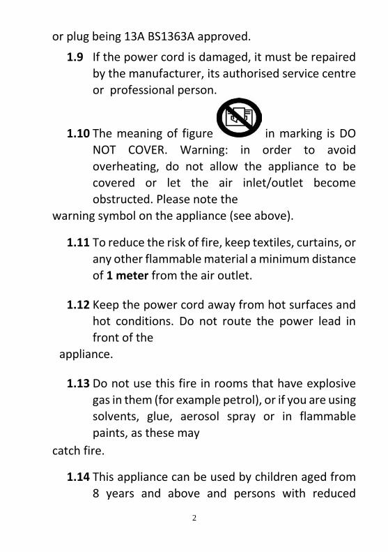
1.10 The meaning of figure in marking is DO
NOT COVER. Warning: in order to avoid
overheating, do not allow the appliance to be
covered or let the air inlet/outlet become
obstructed. Please note the
warning symbol on the appliance (see above).
1.11 To reduce the risk of fire, keep textiles, curtains, or
any other flammable material a minimum distance
of 1 meter from the air outlet.
1.12 Keep the power cord away from hot surfaces and
hot conditions. Do not route the power lead in
front of the
appliance.
1.13 Do not use this fire in rooms that have explosive
gas in them (for example petrol), or if you are using
solvents, glue, aerosol spray or in flammable
paints, as these may
catch fire.
1.14 This appliance can be used by children aged from
8 years and above and persons with reduced

3
physical, sensory or mental capabilities or lack of
experience and knowledge if they have been given
supervision or instruction concerning use of the
appliance in a safe
way and understand the hazards involved.
1.15 Children and vulnerable people must be
supervised at all times when using this appliance,
as some parts can
become very hot and cause burns.
1.16 Do not use this appliance in small rooms when
they are occupied by persons not capable of
leaving the room on their own, unless constant
supervision is provided.
1.17 Children aged from 3 years and less than 8 years
only can switch on/off the appliance provided that
it has been placed or installed in its intended
normal operating position and instructions and
supervisions concerning the safe way of the use of
the appliance are
offered.
1.18 Cleaning and user maintenance shall not be made
by children without supervision.
1.19 This appliance shall not be played with by children.
1.20 Children of less than 3 years should be kept away
unless continuously supervised.

4
Model No.: E129R
Supply Voltage: AC 220-240V 50Hz
Maximum power consumption: 2KW
Power for flame effect: 18W (LED 14W + Motor for flame 4W)
Power for Moodlight: DC12V, 1W, 0.08A
Heat Output:
Nominal heat output (Pnom): 2KW
Minimum heat output(indicative) (Pmin): 1KW
Maximum continuous heat output (Pmax): 2KW
Auxiliary Electricity Consumption:
At nominal heat output (elmax): 12.5W
At minimum heat output (elmin): 12.0W
In standby mode (elSB): 0.36W
2. TECHNICAL SPECIFICAT ION S

5
Type of heat output / room temperature control
Single stage heat output and no room temperature control No
Two or more manual stages, no room temperature control No
With mechanic thermostat room temperature control No
With electronic room temperature control Yes
Electronic room temperature control plus day timer Yes
Electronic room temperature control plus week timer Yes
Other Control Options
Room temperature control, with presence detection No
Room temperature control, with open window detection Yes
With distance control option No
With adaptive start control Yes
With working time limitation No
With black bulb sensor No
3.1 Unpacking the fire carefully, make sure that the appliance is intact with no signs
of damage caused by transport and no part has been exposed to water.
If in doubt, do not use the appliance and contact an authorised service centre.
3.2 Keep plastic wrapping away from children.
3.3 Save the original packaging as this may be required in the event of service
complaint with product.
3.4 Check that all parts are removed from the packing.
3. PARTS AND HARDWARE

6
A.
Firebox (1)
B.
Wall Mount Bracket ( 1 )
NOTE: The wall mount
bracket is attached to the
back of the fire by two
screws.
C.
Instruction (1)
D.
Remote Handset (1)
E.
AAA Battery (2)
F.
Plastic Wall Plugφ8*40 (6)
G.
Screw ST4*10 (2)
H.
Screw ST5*40 (6)

7
Tools Required
A hammer drill, hammer and a screw driver will be needed.
Locating the Appliance
Your new electric fireplace may be installed virtually anywhere in your home. However, when choosing a location ensure that the general instructions are
followed.
5.1 For best results, install out of direct sunlight.
4. APPLIANCE DIMENSIONS
Unit: mm
5. INSTALLATION INSTRU CTIONS

8
5.2 The appliance should be connected to an earthed electrical outlet and it must
be easily accessible to allow disconnection.
Minimum Clearance to Combustibles
Sides························ 200mm
Floor ························ 400mm
Top ·························· 200mm
Back ···························· 0mm
Front ······················· 1 meter Installing the Appliance
5.3 Unscrew the wall mounting bracket from the back of firebox and keep the three
screws. Choose a solid wall or use suitable plasterboard fixings to fix the wall mounting bracket in the position where you want to install the fireplace. Mark
the position for the holes (6 pcs) with a pencil through the bracket on the wall.

9
5.4 Take away the bracket and then drill 6pcs Φ8 holes in the wall. Tap the plastic wall plugs into the holes. If the wall is solid wood, it is not necessary to drill
the holes or use the plastic wall plugs. Then fix the bracket by the ST5X40
screws.
5.5 Fit the slots in the back of firebox over the hooks on the bracket, and carefully
hang the firebox on the bracket. Then secure the screws on both sides.

10
5.5a For the white model with pebble effect, place pebbles on fuel bed as
desired.
5.6 Hang the flat panel glass on the firebox, and secure it with 2pcs ST4X10 screws.
WARNING! Do not operate the appliance if it is damaged or has malfunctioned. If you suspect the appliance is damaged or has malfunctioned call a qualified service engineer to inspect the appliance, and replace any part of the electrical system if necessary, before reuse.
6. OPERATING INSTRUCTIO NS

11
WARNING! To reduce the risk of fire, keep textiles, curtains, or any other
flammable material a minimum distance of 1 meter from the air outlet.
MAKE SURE the plug fits tight in the outlet. Faulty wall outlet connections or loose
plugs can cause the outlet to overheat.
Do not disconnect the power at the mains supply whilst the appliance is running.
Use the functions on the remote to turn the fire off and ensure the mains switch has been moved to the off position before disconnecting.
PREPARATION BEFORE USE
6.1 The appliance can be operated by both remote control and the manual controls
on the appliance.
NOTE: To use both remote and manual functions the manual on/off switch must be in ‘ON’ position. In order to prevent the product becoming too hot, there is 10s delay when turning on the heater and a 10s delay when turning off the heater fan.
Batteries
Ensure that the handset batteries are new and inserted correctly.
Main Power Switch
6.2 The mains power switch is located on the control panel located on the lefthand
side of the heater box.
6.3 Switch ON (—) before operating either the remote or manual controls.
6.4 A long beep is heard to indicate the fire is ready for use.

12
NOTE: The manual button controls basic functions, not a full range of controls.
Use the remote hand set to carry out all functions.
6a.1 The manual buttons are located at the lower right corner of the appliance.
6a.2 Press “LIGHTS ON/OFF” to turn on or turn off both the flame and mood light
at the same time.
6a.3 Press “FLAME” button to select the colour of flame (3 kinds) or return to the
OFF position.
6a.4 Press “MOOD LIGHT” button to select the colour of mood light (13 kinds),
colour-cycle mode or return to the OFF position.
Note: The controls on appliance will lose the memory for all function settings
when the switch is set to the Off Position.
When the remote runs out of power or when you change the batteries, only the
flame function will lose memory and will not affect the timer settings, however,
the clock may need adjusting.
6 a. MANUAL CONT RO L PANEL

13
NOTE: This is thermostatic remote control. The remote should be in the same
room as fireplace and placed on a flat surface. It must be placed away from the
fire so the hot air will not blow on it and affect thermostatic reading.
The communication frequency between the fire and remote has already been set
up. If you cannot use the remote with the fire, please
follow instructions Step.6b34 to initiate this
connection in point.
Standby for Remote Handset
6b.1 The screen shown to the right is when the remote handset is in standby
condition.
Turn on/off Before Day/Time set up
6 b. REMOTE CONTROLS

14
6b.2 Press to turn on the flame effect, turn off
flame effect and heater when in normal mode.
6b.3 Press to turn on/off the flame effect After Day/Time set up under daily and weekly timer mode.
Flame Effect
6b.4 Press to enter the flame effect adjustment screen.
6b.5 Press the ‘←’ and ‘→’ button to select the 3 kinds
of flame effect.
6b.6 Press the ‘+’ and ‘-’ button to select the 5 brightness of flame effect and OFF
settings.
Mood Light
6b.7 Press to enter the mood light adjustment
screen.
6b.8 Press the ‘←’ and ‘→’ button to cycle through the
13 colours of mood light or a colour-cycle mode.
6b.9 Press the ‘+’ and ‘-’ button to select the 5 brightness of
mood light and OFF settings.
Normal Mode
6b.10 Normal control mode is factory set. If it is
not,
then press button until the logo
shows up at the upper right corner of the
screen.

15
6b.11 Press the ‘+’ and ‘-’ button to adjust the setting
temperature from 17℃ to 25℃ by 2 intervals.
6b.12 Press button to turn heat
on/off, ON or OFF will show at
the lower of the screen.
NOTE: It is normal for the fan heater to stop running
for periods of time. This happens because the room
temperature is at or above the temperature set on the
remote control. The heater indicator will be turned off
after 10s if you have the flame ON. The heater
indicator will stay ON if you use the heating function
only.
Count Down Timer
NOTE: This setting is only for normal mode. It allows
the appliance to go into standby after a set period of
time.
6b.13 Press to cycle through the settings from Off and 0.5 hours to 9 hours. The timer logo and
time will show on the screen. The heater must be in the ON position.
The heater can be automatically run by using daily
timer and weekly timer on the remote.
Set up Day, Time and Comfortable temperature
6b.14 Press to turn on the remote handset. Hold
the button for 3 seconds to enter the setting
screen.
6b.15 Press the ‘←’ and ‘→’ button to choose Day, Time
or your comfortable temperature. The character selected will be
highlighted.

16
6b.16 Pressing the ‘+’ and ‘-’ button will adjust the number.
• Time: 24-hour system
• Select your comfortable temperature from 15-25℃.
• Temperature unit: ℃、℉
Daily Timer Heating
6b.17 The following are preset heating periods, which can be altered if desired.
06:00 until 08:30
17:00 until 22:00
6b.18 Press shows at the upper right
corner of the screen, then enter the daily timer
heating mode.
6b.19 Hold the arrow symbol button for 6 seconds to
enter the daily timer setting. Max
3 timed heating periods per day.
• Press ‘←’ or ‘→’ to choose hour or minute, press
‘+’ or ‘-’ to set the time.
• Minute will increase/decrease by 15 minutes per press.
• Hold for 3 seconds or wait for 10 seconds to save and exit the heating time period setting.
6b.20 Adjusting the set temperature
• Press the ‘+’ or ‘-’ button to increase or decrease the temperature on the
basis of your comfortable temperature setting.
• ECO means 2℃ lower than your comfortable temperature setting, ECO-
means 4℃ lower, COMF+ means 2℃ higher, COMF++ means
4℃ higher.
6b.21 To check your daily timer settings, press .
until
17
6b.22 If heating needs to be turned off, it will be
necessary to go back to the Normal Mode to
turn off.
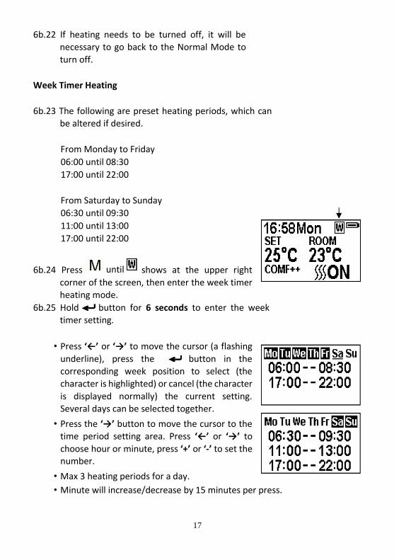
Week Timer Heating
6b.23 The following are preset heating periods, which can be altered if desired.
From Monday to Friday
06:00 until 08:30
17:00 until 22:00
From Saturday to Sunday
06:30 until 09:30
11:00 until 13:00
17:00 until 22:00
6b.24 Press shows at the upper right
corner of the screen, then enter the week timer
heating mode.
6b.25 Hold button for 6 seconds to enter the week timer setting.
• Press ‘←’ or ‘→’ to move the cursor (a flashing
underline), press the button in the corresponding week position to select (the
character is highlighted) or cancel (the character
is displayed normally) the current setting. Several days can be selected together.
• Press the ‘→’ button to move the cursor to the
time period setting area. Press ‘←’ or ‘→’ to
choose hour or minute, press ‘+’ or ‘-’ to set the number.
• Max 3 heating periods for a day.
• Minute will increase/decrease by 15 minutes per press.
until

18
• Press the to set the heating time for the selected day(s) and return to the week line.
• Hold for 3s or wait for 10s to save and exit the heating time
period setting.
6b.26 Press , ‘←’ and ‘→’ to check your week timer
settings.
6b.27 If heating needs to be turned off, it will be
necessary to go back to the Normal Control
Mode to turn off.
Advance Mode
6b.28 Under the daily and week timer mode, Press
:
6b.29 To turn the heater off when the heater is on
during a preset heating period.
6b.30 To turn the heater on when the heater is off in between preset heating
periods.
Adaptive Start Control
6b.31 According to room temperature and
settemperature, the heater will automatically come on in time to heat the room to the set
temperature at the set time. For example, if
your timer is set to start at 18:00 and
temperature is set to 23°C, the fire will come
on at 17:30 to ensure the room is 23°C at
18:00.
Window Open Detection

19
6b.32 When the transmitter detects a rapid drop in
room temperature, it will be judged as a window
open, the warning icon will be displayed and the heating will be turned off automatically.
6b.33 After the indoor temperature has risen or a
manual override of the warning (by operating remote control) has been done, the fire will
return to normal working state.
Set up the communication between the remote and appliance
6b.34 The below operations should be carried out
before programming, when changing to a new remote or in the event the appliance cannot be
controlled by the remote:
• Hold the reset button on the appliance for 3 seconds (pen point may
needed) until you hear 3 short beeps from the unit, release the button.
• Press the button on the remote, the programming is finished when you
hear 1long beep from the appliance.
6b.35 Resetting the code for remote control is necessary if the appliance
operates wrongly or the remote control does not
operate correctly.
• Open the back cover of the remote control.
• Press the Reset button on remote handset.
• Follow the steps 6b.34
Resetting the Thermal Cut Out
6b.36 The appliance is fitted with an Electronic Safety Control (E.S.). This is a safety
device, which switches off the fire if, for any reason, the appliance
overheats, e.g. when covered. If the heater stops operating while the flame
effect continues working normally, this indicates that the E.S. Control is in

20
operation. The E.S. Control can only be re-set after the appliance has cooled
down, and the appliance has been reset. Re-setting of the E.S. Control
proceeds is as follows:
6b.37 Switch off the appliance (Manual On/Off switch) and leave it off for
approximately 10-15 minutes.
6b.38 Remove any obstruction to the fan heater outlet or fan blades etc. Make
sure that the power supply is disconnected with the plug socket outlet while
doing this.
6b.39 Switch on the appliance and the E.S. Control will be re-set.
6b.40 Ensure that the appliance is functioning correctly. If the E.S. Control operates again, the appliance should be checked by a competent electrician.
WARNING: Before any maintenance or cleaning of the exterior of the fireplace,
the unit should be disconnected from the power supply until it is cool off.
Remote Handset Battery Replacement
7.1 When the batteries are at full power, the battery symbol will show
7.2 When the batteries are half full, the battery symbol will show
7.3 When the batteries are out of power and need replacing immediately, the
battery symbol will show
7.4 Battery replacement is recommended after 1 year. The batteries are 1.5V
alkaline AAA, batteries.
7.5 Dispose of old batteries at an appropriate recycling facility.
7 . MAINTENANCE

21
Cleaning the Fireplace
Cleaning or polishing products are not recommended. Fingerprints or other marks
on the front glass panel can be removed by a piece of soft, damp, lint-free cloth
with a good quality household glass cleaner. The front glass panel should always
be completely dried with a clean, lint-free cloth or paper towel.
CAUTION: Abrasive cleaners should not be used on the glass panel. Liquids should
not be sprayed directly onto any surface of the unit.
8. OTHERS
Environment
Meaning of crossed –out wheeled dustbin:
Electrical appliances should not be disposed as unsorted municipal
waste. Separate collection facilities should be used in the disposal
of electrical appliances. Contact your local government for the
information about the available collection systems. If electrical
appliances are disposed of in landfills or dumps, hazardous
substances can leak into the groundwater and get into the food chain, damaging
your health and well-being. When old appliances are replaced by the new ones, it
is a legal oblige for the retailer to take back the old appliance for disposals at least free of charge.
This fire complies with the Safety Standards EN 60335-1 and EN
60335-2-30 which covers the essential requirements of the Low
Voltage Directive 2014/35/EU and the EMC standards EN
55014-1; EN 55014-2; EN 61000-3-2 and EN 61000-3-3 which covers the essential requirements of the European Electro Magnetic Compatibility 2014/30/EU and the
RED standards EN300220-2, EN301489-1, EN301489-3 and EN6247 which covers
the essential requirements of the European Radio Equipment Directive
2014/53/EU.
Control PCB Remote Control Receiver Remote Control Transmitter

22
Hardware: RC01-041A02 Software: 20170926
Hardware: RF290B V1.2 Frequency: ASK/OOK 433.92MHZ Maximum transmit power: 10mW Hardware: RF290A-TX-V1.3 Software: RF290A_C_V0.6.0.hex
Appliance Development Services Ltd
Bakers Court, Hopper Hill Road, Scarborough, N. Yorkshire. YO11 3YS
Tel 01723 583227
3.EF.202.05.051 A2