Embed Size (px)
Citation preview
CONTENTS PAGE
1. NOMENCLATURE ..........................................1
2. DESCRIPTION................................................1
3. MOUNTING ON WALL ...................................2
4. FIELD TERMINATION APPLICATIONS .........2
5. PIGTAIL/SPLICING APPLICATIONS .............2
6. PREPARATION AND ROUTING OF
FEEDER CABLE .........................................2, 3
CONTENTS PAGE
7. PIGTAIL PREPARATION AND ROUTING ..2, 3
8. FIBER SPLICING AND SPLICE TRAY .......3, 4
9. JUMPER ROUTING........................................4
10. ACCESSORIES ..............................................4
11. SAFETY CONSIDERATIONS..........................4
110143302 Rev F 4263
Be sure to read and completely understand this procedure before applying product. Be sure to select
the proper Optical Cable Corporation product before application.
Catalog#
WTC12/24A
WTC12/24B
Product Description (Where color is: A = Almond, B = Black)
Wall Mount Cabinet with Fiber Mgmt System, accepts up to 4 Adapter Plates
Wall Mount Cabinet with Fiber Mgmt System, accepts up to 4 Adapter Plates
SEPTEMBER 2009
WALL MOUNT CABINETS
(for 12 and 24 fibers)
1.00 NOMENCLATURE
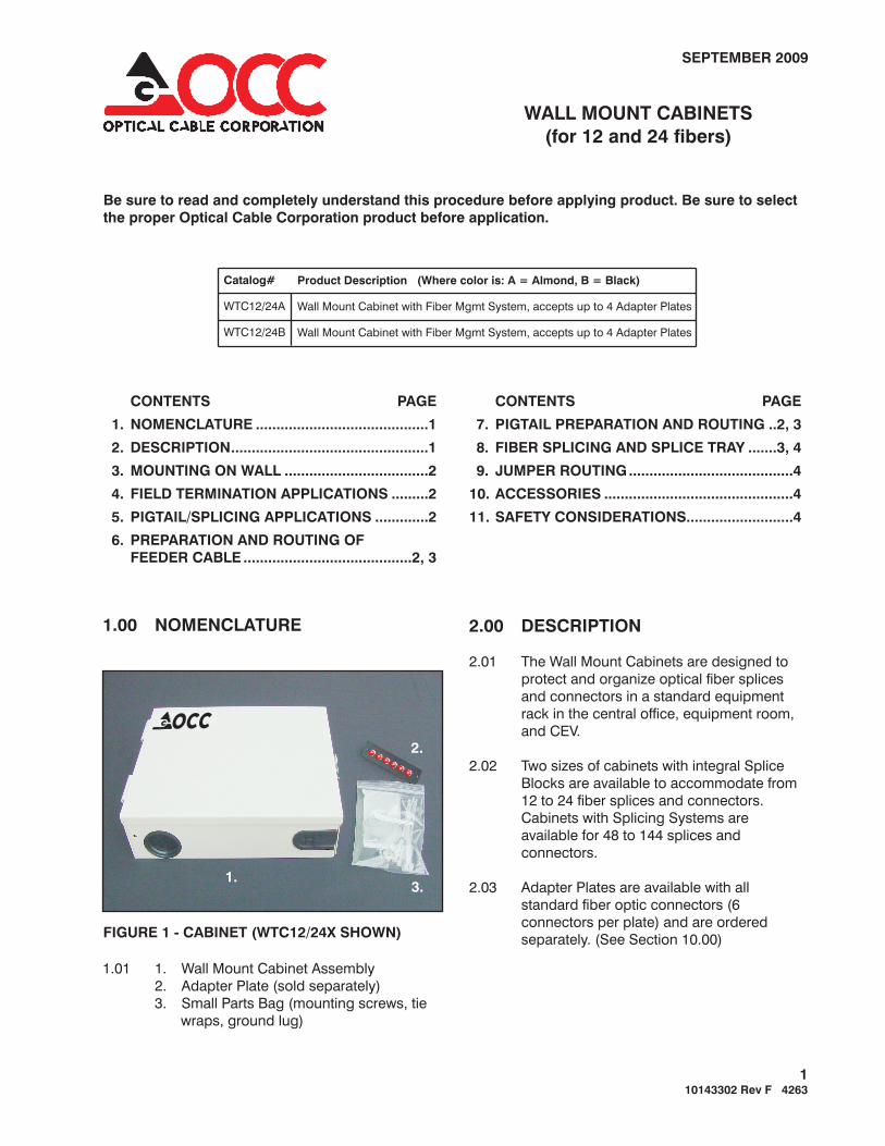
1.01 1. Wall Mount Cabinet Assembly
2. Adapter Plate (sold separately)
3. Small Parts Bag (mounting screws, tie
wraps, ground lug)
2.00 DESCRIPTION
2.01 The Wall Mount Cabinets are designed to
protect and organize optical fiber splices
and connectors in a standard equipment
rack in the central office, equipment room,
and CEV.
2.02 Two sizes of cabinets with integral Splice
Blocks are available to accommodate from
12 to 24 fiber splices and connectors.
Cabinets with Splicing Systems are
available for 48 to 144 splices and
connectors.
2.03 Adapter Plates are available with all
standard fiber optic connectors (6
connectors per plate) and are ordered
separately. (See Section 10.00)FIGURE 1 - CABINET (WTC12/24X SHOWN)
2.
3.1.
OCC

3.00 MOUNTING ON WALL
4.00 FIELD TERMINATION
3.01 Remove the front cover by lifting off the
lower hinge section.
3.02 Remove the cover from splicing chamber (if
provided) by lifting out of the slots on the
left side.
3.03 Position the rear section of cabinet against
the plywood backboard or wall where it is to
be located, level, and mark the center of the
four mounting hole locations.
3.04 If a plywood backboard is used, drill a small
pilot hole at the marks, otherwise install the
appropriate anchors at marked locations.
3.05 Fasten cabinet securely to the wall.
3.06 Secure the ground lug to the hole in the left
side of the cabinet with the 1/4-20 x 1/2”
pan head screw, nut, and lockwasher
included with the ground lug kit.
3.07 Ground the cabinet to an approved ground
with a #6 solid copper wire (or equivalent)
attached to the ground lug.
4.01 Remove the plug from cable entry in the
rear section to be used (top or bottom), and
install the appropriate non-metallic conduit
fitting (if required).
4.02 Install the L-Bracket Assembly adjacent to
the entry being used with the 1/4” screw,
nut, and lock washer provided.
4.03 Feed the cable through the conduit (if
required) into and through the cabinet.
4.04 With the end of the cable jacket extending
about 1-1/2” into the cabinet, remove a
minimum of 60” of jacket to 80” of jacket
from the cable for the WTC12/24X cabinet.
4.05 If required, install a bond connector at the
end of the cable jacket, and secure it to the
L-Bracket Assembly.
4.06 Capture the central strength member or any
other strength member into the clip on the
L-Bracket Assembly.
APPLICATIONS
4.07 Install the Adapter Plates (purchased
separately) in the cabinet bulkhead. Push
the locking fasteners at the ends of the
Adapter Plates to secure them in place.
4.08 Route the individual jacketed fiber elements
around the Fiber Radius Hoops twice, then
through the middle of the Radius Hoops to
the Adapter Plates.
Be sure to maintain a 1-3/4” to 2” bending
radius on the individual fiber elements as they go
around the top or bottom Radius Hoop and through
the center of the Radius Hoops.
4.09 Mark the jacketed fiber elements at a point
about 1” beyond where they contact the
bulkhead (this provides additional fiber
length for application of the connectors).
4.10 Field install the connectors to the jacketed
connector supplier.
4.11 Install the connectorized fiber elements to
the bushings on the Adapter Plates.
5.01 Sections 6.00 through 8.00 detail the steps
required where pigtails are used, and
spliced into the feeder cables within the
cabinet.
6.01 See SECTION 4.00, instructions 4.01
through 4.04 (if required).
6.02 Thoroughly remove all filling compound
from the unitube using your accepted
company practices.
6.03 If required, install a bond connector at the
end of the cable jacket, and secure it to the
L-Bracket Assembly.
6.04 Capture the central strength member and
any other strength member into the clip on
the L-Bracket Assembly.
6.05 Mark the unitube about 3” beyond the end
of the L-Bracket Assembly.
6.06 Remove the unitube up to the mark and
clean according to your accepted company
practices.
TIP:
5.00 PIGTAIL/SPLICING
6.00 PREPARATION AND ROUTING OF
APPLICATIONS
FEEDER CABLE
2
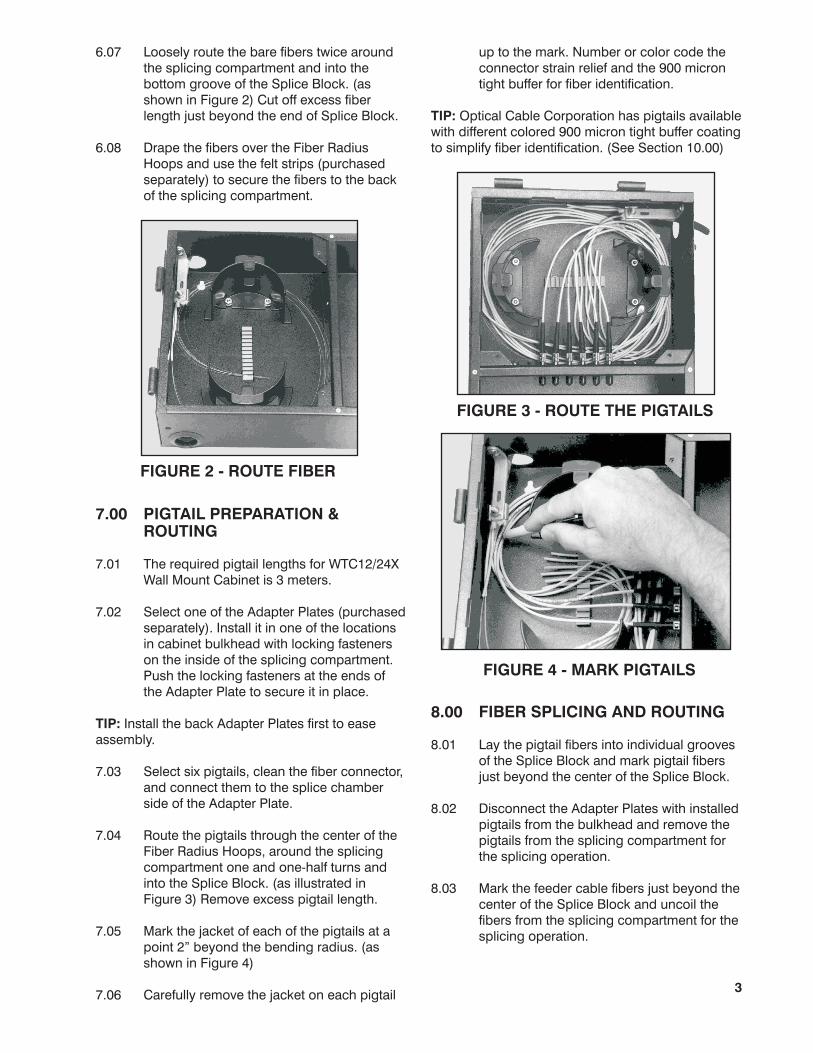
FIGURE 4 - MARK PIGTAILS
6.07 Loosely route the bare fibers twice around
the splicing compartment and into the
bottom groove of the Splice Block. (as
shown in Figure 2) Cut off excess fiber
length just beyond the end of Splice Block.
6.08 Drape the fibers over the Fiber Radius
Hoops and use the felt strips (purchased
separately) to secure the fibers to the back
of the splicing compartment.
7.01 The required pigtail lengths for WTC12/24X
Wall Mount Cabinet is 3 meters.
7.02 Select one of the Adapter Plates (purchased
separately). Install it in one of the locations
in cabinet bulkhead ers
on the inside of the splicing compartment.
Push the locking
Install the back Adapter Plates first to ease
assembly.
7.03 Select six pigtails, clean the fiber connector,
and connect them to the splice chamber
side of the Adapter Plate.
7.04 Route the pigtails through the center of the
Fiber Radius Hoops, around the splicing
compartment one and one-half turns and
into the Splice Block. (as illustrated in
Figure 3) Remove excess pigtail length.
7.05 Mark the jacket of each of the pigtails at a
point 2” beyond the bending radius. (as
shown in Figure 4)
7.06 Carefully remove the jacket on each pigtail
7.00 PIGTAIL PREPARATION &ROUTING
with locking fasten
fasteners at the ends of
the Adapter Plate to secure it in place.
TIP:
up to the mark. Number or color code the
connector strain relief and the 900 micron
tight buffer for fiber identification.
Optical Cable Corporation has pigtails available
with different colored 900 micron tight buffer coating
to simplify fiber identification. (See Section 10.00)
TIP:
FIGURE 3 - ROUTE THE PIGTAILS
FIGURE 2 - ROUTE FIBER
3
8.00 FIBER SPLICING AND ROUTING
8.01 Lay the pigtail fibers into individual grooves
of the Splice Block and mark pigtail fibers
just beyond the center of the Splice Block.
8.02 Disconnect the Adapter Plates with installed
pigtails from the bulkhead and remove the
pigtails from the splicing compartment for
the splicing operation.
8.03 Mark the feeder cable fibers just beyond the
center of the Splice Block and uncoil the
fibers from the splicing compartment for the
splicing operation.

TIP:
TIP:
Use felt tape (purchased separately) to secure
the fibers to the back of the splicing compartment
just beyond the end of the unitube to avoid undue
bending of the fibers during this operation.
8.04 Splice the pigtail fibers to the feeder cable
fibers using accepted company practices.
Use the cover of the splicing compartment
(purchased separately) as a worktable by placing it
into grooves at the bottom of splicing compartment.
8.05 Lay the completed splices into individual
grooves of the Splice Block.
9.01 Clean the fiber connectors and attach the
jumpers to right side of the Adapter Plates.
9.02 Gently bend the jumpers toward and
through the grommet on either the top or
bottom of the cabinet.
9.03 Lightly secure the jumpers to the tie down
post with the tie wraps provided.
10.01 Table 1 details the Adapter Plates and
Pigtail Assemblies available for the Wall
Mount Cabinets.
9.00 JUMPER ROUTING
10.00 ACCESSORIES
11.00 SAFETY CONSIDERATIONS
11.01
11.02
11.03
11.04
should not
be used
This application procedure is not intended
to supersede any company construction or
safety standards. This procedure is offered
only to illustrate safe application for the
individual. Failure to follow these
procedures may result in personal injury.
When working in the area of energized
lines, extra care should be taken to prevent
accidental electrical contact.
For proper performance and personal
safety, be sure to select the proper size
Optical Cable Corporation product before
application.
This product is intended for use by trained
technicians only. The product
by anyone who is not familiar with,
and not trained to use it.
NOTE: Contact Optical Cable Corporation for additional
adapter plates and pigtail assemblies.
TABLE 1
ADAPTER PLATE ASSEMBLIES
12 FIBER PIGTAIL ASSEMBLIES
Catalog# Description
Catalog# Description
616MMST Plate equipped with 6 multimode ST adapters
616SMST Plate equipped with 6 singlemode ST adapters
616MMSC Plate equipped with 6 multimode SC adapters
616SMSC Plate equipped with 6 singlemode SC adapters
616MMFC Plate equipped with 6 multimode FC adapters
616SMFC Plate equipped with 6 singlemode FC adapters
616MMDLC Equipped with 3 multimode duplex LC adapters
616SMDLC Equipped with 3 singlemode duplex LC adapters
600 Blank Filler Plate (no port holes or adapters)
P5ST12-3M 12 fibers with different colored 900µm buffers,3 meters long, 50µm multimode ST connectors
P6ST12-3M 12 fibers with different colored 900µm buffers,3 meters long, 62.5µm multimode ST connectors
P8ST12-3M 12 fibers with different colored 900µm buffers,3 meters long, 9µm singlemode ST connectors
P5SC12-3M 12 fibers with different colored 900µm buffers,3 meters long, 50µm multimode SC connectors
P6SC12-3M 12 fibers with different colored 900µm buffers,3 meters long, 62.5µm multimode SC connectors
P8SC12-3M 12 fibers with different colored 900µm buffers,3 meters long, 9µm singlemode SC connectors
P5FC12-3M 12 fibers with different colored 900µm buffers,3 meters long, 50µm multimode FC connectors
P6FC12-3M 12 fibers with different colored 900µm buffers,3 meters long, 62.5µm multimode FC connectors
P8FC12-3M 12 fibers with different colored 900µm buffers,3 meters long, 9µm singlemode FC connectors
P5LC12-3M 12 fibers with different colored 900µm buffers,3 meters long, 50µm multimode LC connectors
P6LC12-3M 12 fibers with different colored 900µm buffers,3 meters long, 62.5µm multimode LC connectors
P8LC12-3M 12 fibers with different colored 900µm buffers,3 meters long, 9µm singlemode LC connectors
410143302 Rev F 4263
5290 Concourse Drive • Roanoke, VA 24019 USAPhone: 540-265-0690 • TOLL FREE 800-622-7711
Fax: 540-265-0724 www.occfiber.com•