Embed Size (px)
DESCRIPTION
INSTALLATION AND MAINTENANCE INSTRUCTIONS
Citation preview
MAXXTM22T – MECHANICAL SLIDING CALIPER DISC BRAKE
INSTALLATION ANDMAINTENANCE INSTRUCTIONS


MAXXTM22T
Mechanical Sliding caliper diSc Brake inStallation and Maintenance inStructionS edition 1 this publication is not subject to any updating service. You will find new versions on the internet at http://www.wabco.info/8152202163
© 2014 WaBco europe BVBa – all rights reserved
Subject to change without notice Version 2 / 10.2014(en-uS)
815 220 216 3


3
MAXXTM22T
1 Disclaimer ............................................................................................................................................. 4
2 Symbols used ...................................................................................................................................... 5
3 Safety instructions .............................................................................................................................. 6
4 Introduction .......................................................................................................................................... 8
5 Description of the disc brake ............................................................................................................. 9
6 Checking the brake ............................................................................................................................ 126.1 checking the adjuster . . . . . . . . . . . . . . . . . . . . . . . . . . . . . . . . . . . . . . . . . . . . . . . . . . . . . . . 126.2 checking the brake linings . . . . . . . . . . . . . . . . . . . . . . . . . . . . . . . . . . . . . . . . . . . . . . . . . . . . 15
6.2.1 Measuring the brake lining thickness ............................................................................ 166.2.2 other measurements of the brake lining thickness ....................................................... 17
6.3 inspecting the brake discs . . . . . . . . . . . . . . . . . . . . . . . . . . . . . . . . . . . . . . . . . . . . . . . . . . . . 186.3.1 checking the condition of the brake discs ..................................................................... 196.3.2 checking the runout of the brake discs ......................................................................... 19
6.4 checking the bearing play of the guide pin . . . . . . . . . . . . . . . . . . . . . . . . . . . . . . . . . . . . . . . 20
7 Replacing the brake linings .............................................................................................................. 227.1 removing the brake linings . . . . . . . . . . . . . . . . . . . . . . . . . . . . . . . . . . . . . . . . . . . . . . . . . . . 227.2 checking the protection caps and the ability of the brake caliper to move . . . . . . . . . . . . . . . 267.3 checking the adjuster unit (clamping unit) . . . . . . . . . . . . . . . . . . . . . . . . . . . . . . . . . . . . . . . . 287.4 Fitting the brake linings . . . . . . . . . . . . . . . . . . . . . . . . . . . . . . . . . . . . . . . . . . . . . . . . . . . . . . 29
8 Replacing the brake cylinder ............................................................................................................ 338.1 removing the brake cylinder . . . . . . . . . . . . . . . . . . . . . . . . . . . . . . . . . . . . . . . . . . . . . . . . . . 338.2 installing the brake cylinder . . . . . . . . . . . . . . . . . . . . . . . . . . . . . . . . . . . . . . . . . . . . . . . . . . . 34
9 Renewing the brake ........................................................................................................................... 369.1 removing the brake . . . . . . . . . . . . . . . . . . . . . . . . . . . . . . . . . . . . . . . . . . . . . . . . . . . . . . . . . 369.2 installing the brake . . . . . . . . . . . . . . . . . . . . . . . . . . . . . . . . . . . . . . . . . . . . . . . . . . . . . . . . . . 37
10 Renewing the seals ........................................................................................................................... 3910.1 renewing the protection caps and the bushings of the guide pins . . . . . . . . . . . . . . . . . . . . . 39
10.1.1 disassembly .................................................................................................................. 3910.1.2 assembly ....................................................................................................................... 42
10.2 renewing the protection cap of the adjuster screw . . . . . . . . . . . . . . . . . . . . . . . . . . . . . . . . . 5010.2.1 removing the protection cap ......................................................................................... 5010.2.2 Fitting the protection cap ............................................................................................... 53
10.3 renewing the protection cap for the adjuster hexagon . . . . . . . . . . . . . . . . . . . . . . . . . . . . . . 5510.3.1 removing the protection cap ......................................................................................... 5510.3.2 Fitting the protection cap ............................................................................................... 56
11 Annex .................................................................................................................................................. 6011.1 tools, spanner widths and tightening torques . . . . . . . . . . . . . . . . . . . . . . . . . . . . . . . . . . . . . 6011.2 WaBco tools . . . . . . . . . . . . . . . . . . . . . . . . . . . . . . . . . . . . . . . . . . . . . . . . . . . . . . . . . . . . . . 6111.3 exploded view of the replacement parts . . . . . . . . . . . . . . . . . . . . . . . . . . . . . . . . . . . . . . . . . 6311.4 procurement and disposal of spare parts . . . . . . . . . . . . . . . . . . . . . . . . . . . . . . . . . . . . . . . . 6411.5 disposing of the brake components . . . . . . . . . . . . . . . . . . . . . . . . . . . . . . . . . . . . . . . . . . . . . 64
Table of Contents
4
MAXXTM22T Disclaimer
1 DisclaimerWe assume no liability for the correctness, completeness or up-to-dateness of the information in this document. all technical information, descriptions and images are applicable for the date on which this document or respective supplements were printed. We reserve the right to make any changes as a result of continuous further development.
the content of this document provides no guarantees nor warranted characteristics nor can it be construed as such. liability for damage is strictly excluded unless it is based upon intent or gross negligence on our part or unless this contradicts other mandatory statuary regulations.
text and graphics are subject to our right of use; copying or distribution in any form requires our approval. any brand markings, even if not indicated as such, are subject to the rules of the labelling rights. if legal disputes arise from the utilization of the information in this document, these are exclusively to be handled under the regulations of national law.
in so far as components or individual formulations of this applicable legal status documentation are no longer or not fully relevant, the remaining parts of the documentation remain unaffected thereby in their content and validity.

5
MAXXTM22TSymbols used
2 Symbols used
WARNING Type and source of hazardpotential hazard situation which can cause serious personal injury or death if the safety instruction is not observed.
– Follow this step to ward off the hazard.
CAUTION Type and source of hazardpotential hazard situations that can cause minor or medium-severe personal injury if the safety instruction is not observed.
– Follow this step to ward off the hazard.
CAUTION Type and source of hazardpotential hazard situations that can cause material loss if the safety instruction is not observed.
– Follow this step to ward off the hazard.
! important instructions, information, or tips that you should always observe.
reference to information on the internet
– action step Ö consequence of an action
� list

6
MAXXTM22T Safety instructions
3 Safety instructions
Observe all required provisions and instructions:
– Before you begin with maintenance, repair, replacing a part etc., carefully read all the safety instructions as well as the repair and maintenance instructions included this publication. adhere to all instructions, information and safety information to prevent injury to persons and damage to property.
– WaBco will only guarantee the security, reliability and performance of their products and systems if all information in this publication is adhered to.
– Always follow the specifications and instructions of the vehicle manufacturer.
– observe all accident regulations of the respective company as well as regional and national regulations.
Make provisions for a safe work environment:
– The workplace has to be dry, as well as sufficiently lit and ventilated.
– Only trained and qualified technicians are to perform work on the vehicle.
– use personal protective equipment if required (protective goggles, respiratory protection, ear protectors, etc.).
pedal actuations can lead to severe injuries if persons are in the vicinity of the vehicle. Make sure that pedals cannot be actuated as follows:
– Switch the transmission to "neutral" and actuate the park brake.
– position the vehicle on an even surface and secure it against rolling away with brake wedges. only use approved devices to jack up and secure the vehicle.
– Fasten a visible note to the steering wheel indicating that work is being performed on the vehicle and that the pedals are not to be actuated.
Avoid any reduced braking effect or brake failure:
– regularly check the wear limits of brake linings and brake discs.
– immediately replace worn or damaged brake discs.
– always replace brake linings by axle and use a new retaining system for brake linings and pressure plates.
– if cast parts have been heavily damaged or are severely worn, (cracks for example), replace the entire brake following the instructions.
7
MAXXTM22TSafety instructions
Note the following safety instructions for safe repairs, testing and maintenance:
For good handling and braking characteristics it is essential that the disc brake is in flawless technical condition.
– do not clean any soiled areas of the brake with compressed air or other high-pressure devices.
– a second technician must assist during removal and installation of the brake.
– only grip the brake on the outside with your hands while moving the brake caliper or working on the brake.
– use suitable equipment, such as a vice, to clamp the brake when performing repairs on the brake outside the vehicle.
– never use the lining retainer clip as a grab handle or for fastening a lifting device, because the lining retainer clip can be damaged in the process.
– do not open the brake caliper with the actuating unit, and do not unscrew the fastening screws on the brake caliper cover.
– do not apply the brake when brake linings have been removed.
– do not use compressed air or other high-pressure devices when cleaning the brake or the vehicle. hazardous dusts arising may lead to injuries. rubber parts of the brake could also be damaged.
– only use original WaBco parts and approved brake linings and retaining systems for brake linings and pressure plates. an exploded view of replacement parts is found in the annex of this document, see chapter “11.3 exploded view of the replacement parts” on page 63.
– only use grease contained in the repair kits.
– perform the repair work using only the recommended tools, see chapter “11.2 WaBco tools” on page 61. do not use motor-driven screw or torque tools!
– Tighten screws and nuts only with the specified spanners, applying only the specified tightening torque; refer to the table in the annex, see chapter “11.1 tools, spanner widths and tightening torques” on page 60, for the corresponding positions.
– Make sure that the release screw of the spring brake cylinder is threaded completely in after completing the maintenance and installation work and check the functionality of the parking brake.
– perform a concluding roller test stand test having completed the repairs. if no roller test stand is available, conduct a test drive with brake action tests.
– do not perform full braking, with the exception of emergency braking, during the first 50 kilometers after new brake linings have been fitted. also avoid continuous braking over longer periods. ensure that the driver of the vehicle is informed.

8
MAXXTM22T Introduction
4 Introductionthis publication describes maintenance and repair of the mechanical sliding caliper disc brake MaXXtM22t including the individual operations and work processes required to replace components using available repair kits.
Wheel brake product numbers
640 222 005 0
640 222 006 0
640 222 007 0
640 222 008 0
9
MAXXTM22TDescription of the disc brake
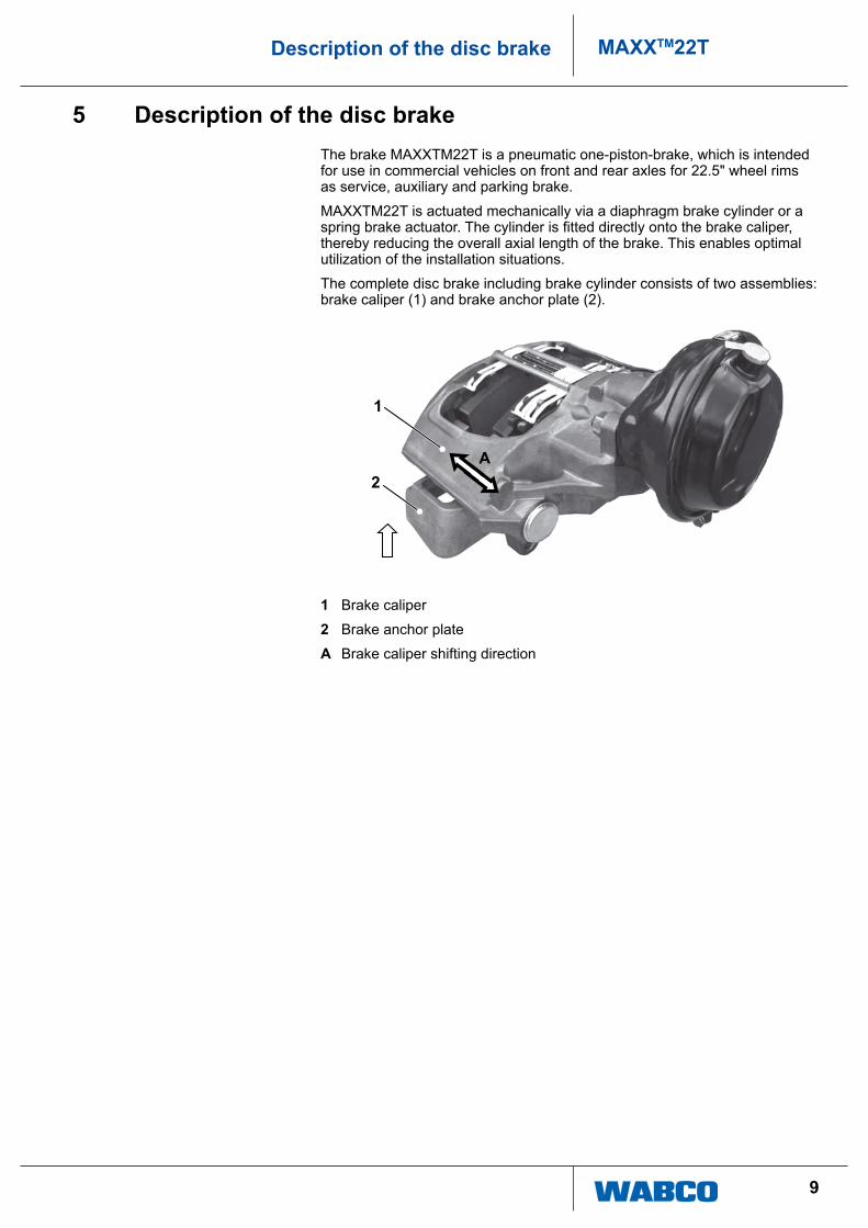
5 Description of the disc brakethe brake MaXXtM22t is a pneumatic one-piston-brake, which is intended for use in commercial vehicles on front and rear axles for 22.5" wheel rims as service, auxiliary and parking brake.
MaXXtM22t is actuated mechanically via a diaphragm brake cylinder or a spring brake actuator. The cylinder is fitted directly onto the brake caliper, thereby reducing the overall axial length of the brake. this enables optimal utilization of the installation situations.
the complete disc brake including brake cylinder consists of two assemblies: brake caliper (1) and brake anchor plate (2).
1
2A
1 Brake caliper
2 Brake anchor plate
A Brake caliper shifting direction
10
MAXXTM22T Description of the disc brake
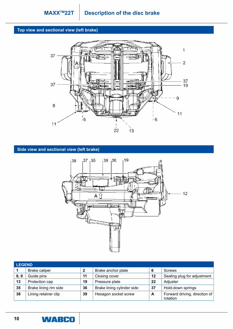
Top view and sectional view (left brake)
Side view and sectional view (left brake)
LeGeND1 Brake caliper 2 Brake anchor plate 6 Screws8, 9 guide pins 11 closing cover 12 Sealing plug for adjustment13 protection cap 19 pressure plate 22 adjuster35 Brake lining rim side 36 Brake lining cylinder side 37 hold-down springs 38 lining retainer clip 39 hexagon socket screw A Forward driving, direction of
rotation
11
MAXXTM22TDescription of the disc brake
Functional description
axial movement of the brake caliper (1) occurs on the guide pins (8, 9) of the brake anchor plate (2). the brake linings (35, 36) are guided and supported axially movable in the brake anchor plate. the brake lining support is implemented by means of a lining retainer clip (38) and hold-down springs (37).
the radially open design of the brake caliper enables simple and quick brake lining replacements.
Brake pads with a large wear volume are used in order to prolong the pad intervals with this brake.
For compensating the pad wear the actuating mechanism of the brake is equipped with a force-dependent, stageless, automatic adjuster mechanism. this mechanism maintains a preset clearance regardless of load and operating conditions. this, together with the stable and stiff construction of the brake caliper, results in safe control of the pedal travel and increases the reserve of travel for emergency braking.
All rubber parts and the grease fillings are maintenance-free except when damaged.
! exploded view with all parts called out, see chapter “11.3 exploded view of the replacement parts” on page 63.

12
MAXXTM22T Checking the brake
6 Checking the brake
! observe all safety instructions, see chapter “3 Safety instructions” on page 6. these instructions must be observed to avoid personal injury and/or material damage.
6.1 Checking the adjuster
! directions of rotation and torques of the hexagon nut of the adjuster are listed in the table in the annex, see chapter “11.1 tools, spanner widths and tightening torques” on page 60, item i.
the brake cylinder does not need to be dismantled in order to check the brake. the brake is shown without the brake cylinder for illustration purposes only.
Brake linings and pressure plate must be fitted in order to check the adjuster.
Brake linings and pressure plate are fully fitted with a retaining system.
CAUTION Damage to the inner seal from incorrect use of the tooldamage can occur at the inner seal when the tool is positioned between brake caliper and outer side of the sealing ring.
– Position the tool at the sealing plug when removing it (see following illustrations).
13
MAXXTM22TChecking the brake
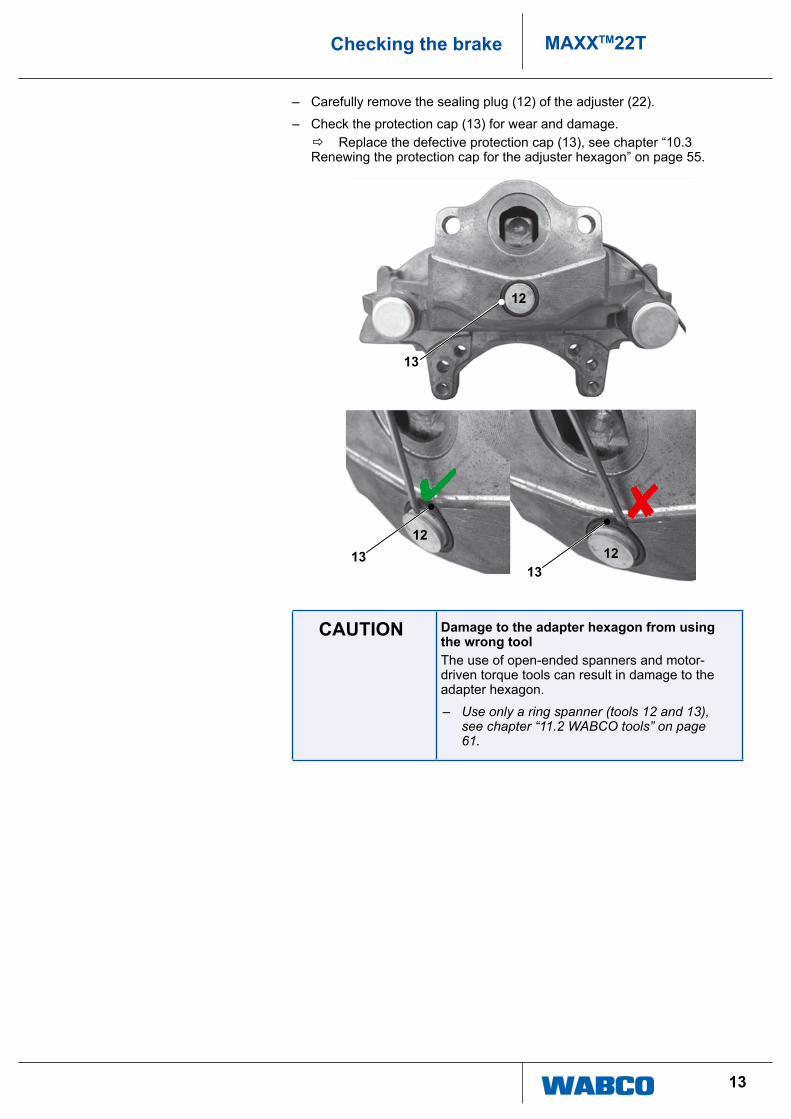
– carefully remove the sealing plug (12) of the adjuster (22).
– check the protection cap (13) for wear and damage. Ö replace the defective protection cap (13), see chapter “10.3
renewing the protection cap for the adjuster hexagon” on page 55.
12
1312
12
13
13
CAUTION Damage to the adapter hexagon from using the wrong toolthe use of open-ended spanners and motor-driven torque tools can result in damage to the adapter hexagon.
– Use only a ring spanner (tools 12 and 13), see chapter “11.2 WABCO tools” on page 61.
14
MAXXTM22T Checking the brake
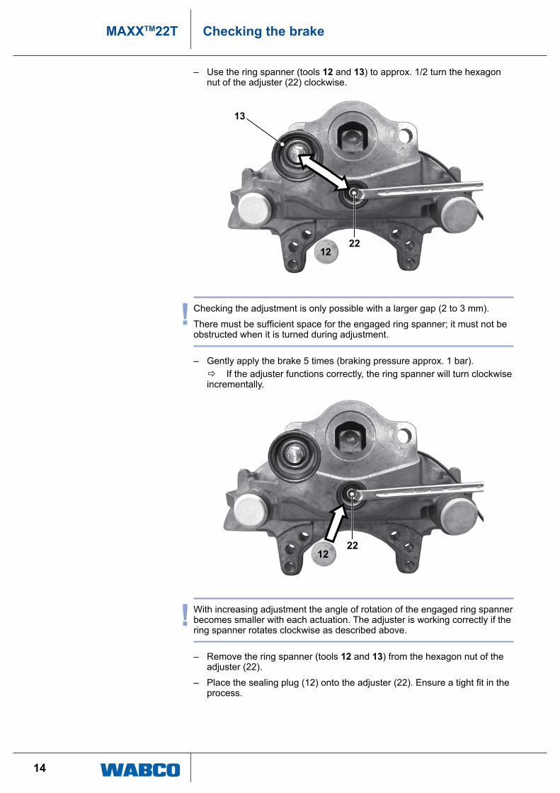
– use the ring spanner (tools 12 and 13) to approx. 1/2 turn the hexagon nut of the adjuster (22) clockwise.
1222
13
! checking the adjustment is only possible with a larger gap (2 to 3 mm).
There must be sufficient space for the engaged ring spanner; it must not be obstructed when it is turned during adjustment.
– gently apply the brake 5 times (braking pressure approx. 1 bar). Ö if the adjuster functions correctly, the ring spanner will turn clockwise
incrementally.
1222
! With increasing adjustment the angle of rotation of the engaged ring spanner becomes smaller with each actuation. the adjuster is working correctly if the ring spanner rotates clockwise as described above.
– remove the ring spanner (tools 12 and 13) from the hexagon nut of the adjuster (22).
– Place the sealing plug (12) onto the adjuster (22). Ensure a tight fit in the process.
15
MAXXTM22TChecking the brake
Faults that might occur
� the adjuster (22) or the attached ring spanner does not turn. � The adjuster (22) or the attached ring spanner only rotates with the first
actuation. � the adjuster (22) or the attached ring spanner rotates back and forth with
every actuation.
in these cases the adjuster is faulty and the brake must be replaced, see chapter “9 renewing the brake” on page 36.
6.2 Checking the brake linings
! the brake lining thickness must be checked at regular intervals, in relation to vehicle use, during maintenance intervals, as well as in the context of applicable local laws and regulations.
Burned, glazed or oil-contaminated brake linings must be replaced immediately.
always replace all brake linings by axle, using a new retaining system for brake linings and pressure plates.
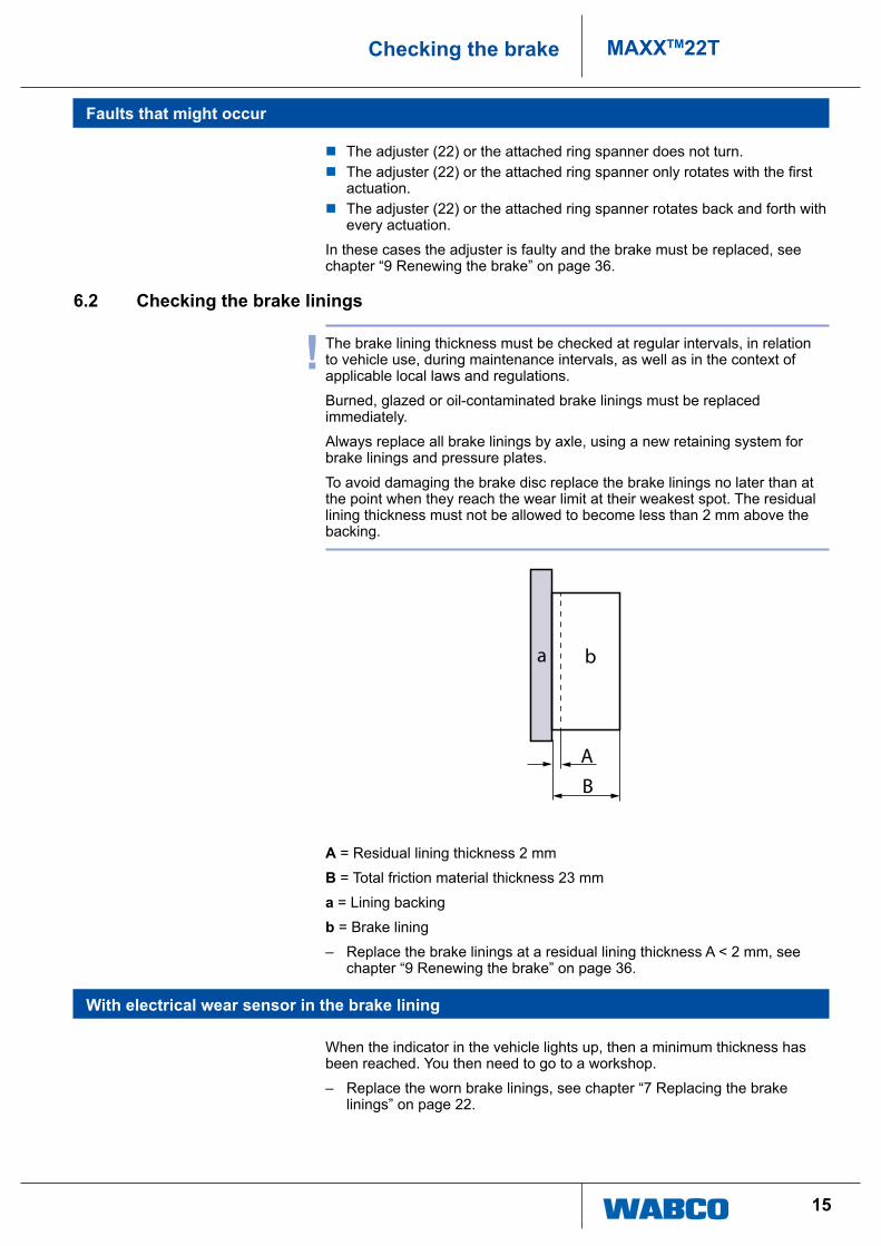
to avoid damaging the brake disc replace the brake linings no later than at the point when they reach the wear limit at their weakest spot. the residual lining thickness must not be allowed to become less than 2 mm above the backing.
AB
a b
A = residual lining thickness 2 mm
B = total friction material thickness 23 mm
a = lining backing
b = Brake lining
– replace the brake linings at a residual lining thickness a < 2 mm, see chapter “9 renewing the brake” on page 36.
With electrical wear sensor in the brake lining
When the indicator in the vehicle lights up, then a minimum thickness has been reached. You then need to go to a workshop.
– replace the worn brake linings, see chapter “7 replacing the brake linings” on page 22.
16
MAXXTM22T Checking the brake
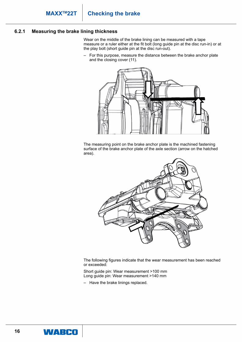
6.2.1 Measuring the brake lining thicknessWear on the middle of the brake lining can be measured with a tape measure or a ruler either at the fit bolt (long guide pin at the disc run-in) or at the play bolt (short guide pin at the disc run-out).
– For this purpose, measure the distance between the brake anchor plate and the closing cover (11).
the measuring point on the brake anchor plate is the machined fastening surface of the brake anchor plate of the axle section (arrow on the hatched area).
The following figures indicate that the wear measurement has been reached or exceeded:
Short guide pin: Wear measurement >100 mm long guide pin: Wear measurement >140 mm
– have the brake linings replaced.
17
MAXXTM22TChecking the brake
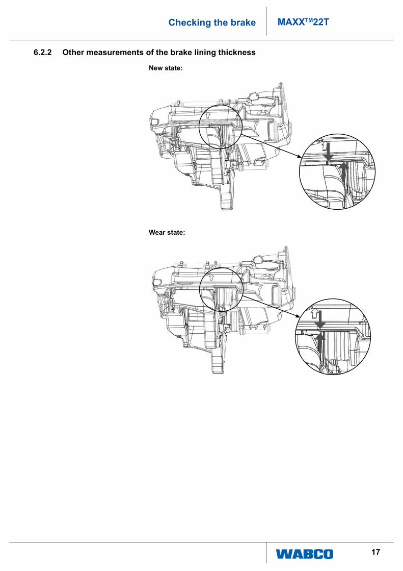
6.2.2 Other measurements of the brake lining thickness
New state:
Wear state:

18
MAXXTM22T Checking the brake
6.3 Inspecting the brake discs
! regularly check the wear limits of brake linings and brake discs.
When brake linings and/or brake discs are worn, the braking effect is reduced and there is a risk of brake failure. replace brake discs and brake linings.
always replace all brake discs by axle.
the brake discs must be clean and free from grease.
having installed new brake discs, it is recommended that new brake linings be fitted as well.
– remove the brake linings, see chapter “7.1 removing the brake linings” on page 22.
– Measure the brake disc thickness at the contact area of the brake linings.
E
C
D
F G
H
C total thickness new disc (43 mm)
D Wear allowance limit 37 mm The brake disc must be renewed. The renewal is recommended on a per axle basis.
e total thickness new brake lining 32 mm
F lining backplate 9 mm
G Minimum brake lining thickness 2 mm
H absolute minimum lining and lining backplate thickness 11 mm The brake linings must be renewed.
19
MAXXTM22TChecking the brake
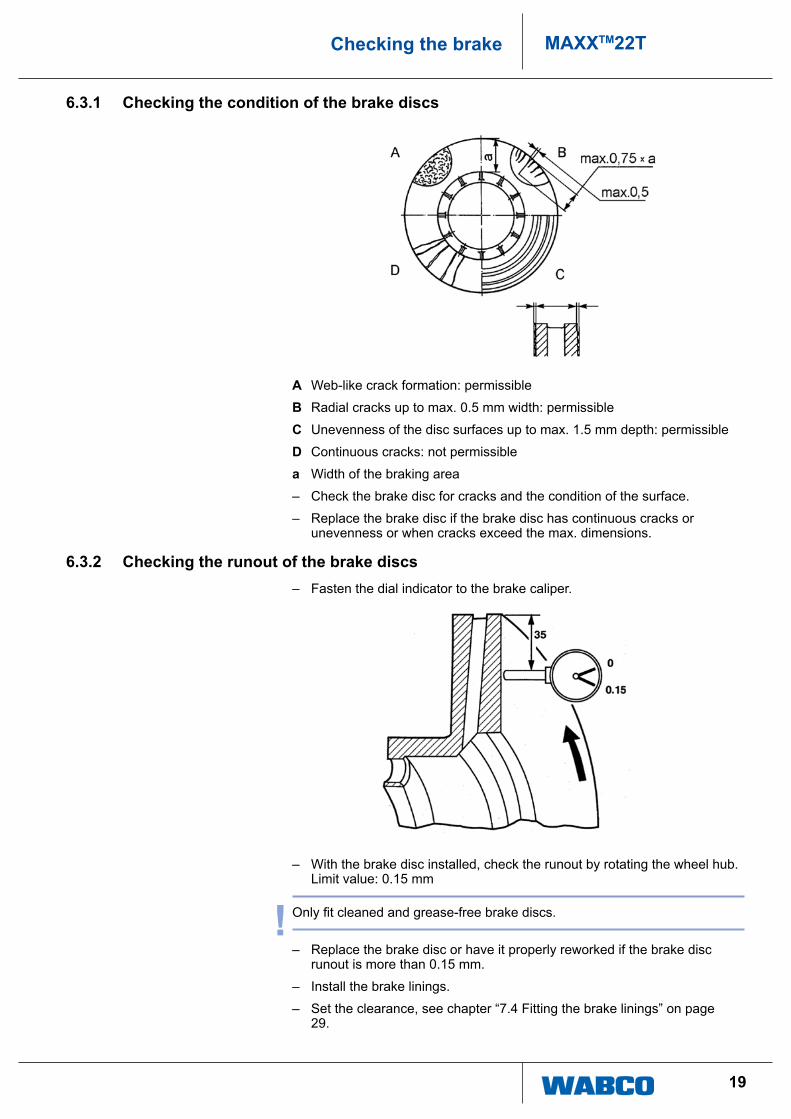
6.3.1 Checking the condition of the brake discs
A Web-like crack formation: permissible
B radial cracks up to max. 0.5 mm width: permissible
C unevenness of the disc surfaces up to max. 1.5 mm depth: permissible
D continuous cracks: not permissible
a Width of the braking area
– check the brake disc for cracks and the condition of the surface.
– replace the brake disc if the brake disc has continuous cracks or unevenness or when cracks exceed the max. dimensions.
6.3.2 Checking the runout of the brake discs – Fasten the dial indicator to the brake caliper.
– With the brake disc installed, check the runout by rotating the wheel hub. limit value: 0.15 mm
! Only fit cleaned and grease-free brake discs.
– replace the brake disc or have it properly reworked if the brake disc runout is more than 0.15 mm.
– install the brake linings.
– Set the clearance, see chapter “7.4 Fitting the brake linings” on page 29.

20
MAXXTM22T Checking the brake
6.4 Checking the bearing play of the guide pin – remove the vehicle wheel in accordance with the instructions of the axle
and/or vehicle manufacturer.
– remove the brake linings and the pressure plate, see chapter “7.1 removing the brake linings” on page 22.
– push the brake caliper completely to the rim side by hand.
– Fasten the magnetic dial indicator support to the brake anchor plate or the axle.
– clean the measuring point. the measuring point is the molded edge on the brake caliper on the rim side (see arrow).
– press the dial indicator against the measuring point (see arrow) on the brake caliper.
– applying little force, tilt the brake caliper as far as possible (direction as illustrated in picture) and set the dial indicator to the value zero.

21
MAXXTM22TChecking the brake
– now - again applying little manual force - tilt the brake caliper as far as possible in the opposite direction.
– read the dial indicator. Ö the bearing play must not be greater than 2 mm.
– renew the bushings of the guide pins if the measured bearing play is greater than 2 mm, see chapter “10.1 renewing the protection caps and the bushings of the guide pins” on page 39.
– remove the dialing indicator.
– install pressure plate and brake linings and adjust the clearance, see chapter “7.4 Fitting the brake linings” on page 29.
– Mount the vehicle wheel in accordance with the instructions of the axle or vehicle manufacturer.
– having completed the work, test the brake on a roller test stand.

22
MAXXTM22T Replacing the brake linings
7 Replacing the brake linings
! observe all safety instructions, see chapter “3 Safety instructions” on page 6. these instructions must be observed to avoid personal injury and/or material damage.
CAUTION Griping brake from inside may cause injuries – Grip brake from for outside edges.
7.1 Removing the brake linings
! the brake cylinder does not need to be dismantled in order to replace the brake linings. the brake is shown without the brake cylinder for illustration purposes only.
always replace the brake linings by axle and use a new retaining system for brake linings and pressure plates. retainer springs are already preassembled on the brake linings.
– remove the vehicle wheel in accordance with the instructions of the axle or vehicle manufacturer.
– loosen the hexagon socket screw (39) from the lining retainer (38), see chapter “11.1 tools, spanner widths and tightening torques” on page 60, item ii. apply slight pressure on the lining retainer clip (38) with your hand at the same time.
38
39

23
MAXXTM22TReplacing the brake linings
– the lining retainer clip (38) has to be withdrawn from the brake caliper (1).
38
1
– remove the retainer spring (37) from the pressure plate (19).
! the retainer springs (37) of the brake linings (35, 36) are crimped to them and cannot be detached.
19, 36, 37
35, 37
– carefully remove the sealing plug (12) of the adjuster (22) from the caliper (1).
CAUTION Damage to the inner seal from incorrect use of the tooldamage can occur at the inner seal when the tool is positioned between brake caliper and outer side of the sealing ring.
– Position the tool at the sealing plug when removing it.
– carefully remove the sealing plug (12) of the adjuster (22).
24
MAXXTM22T Replacing the brake linings
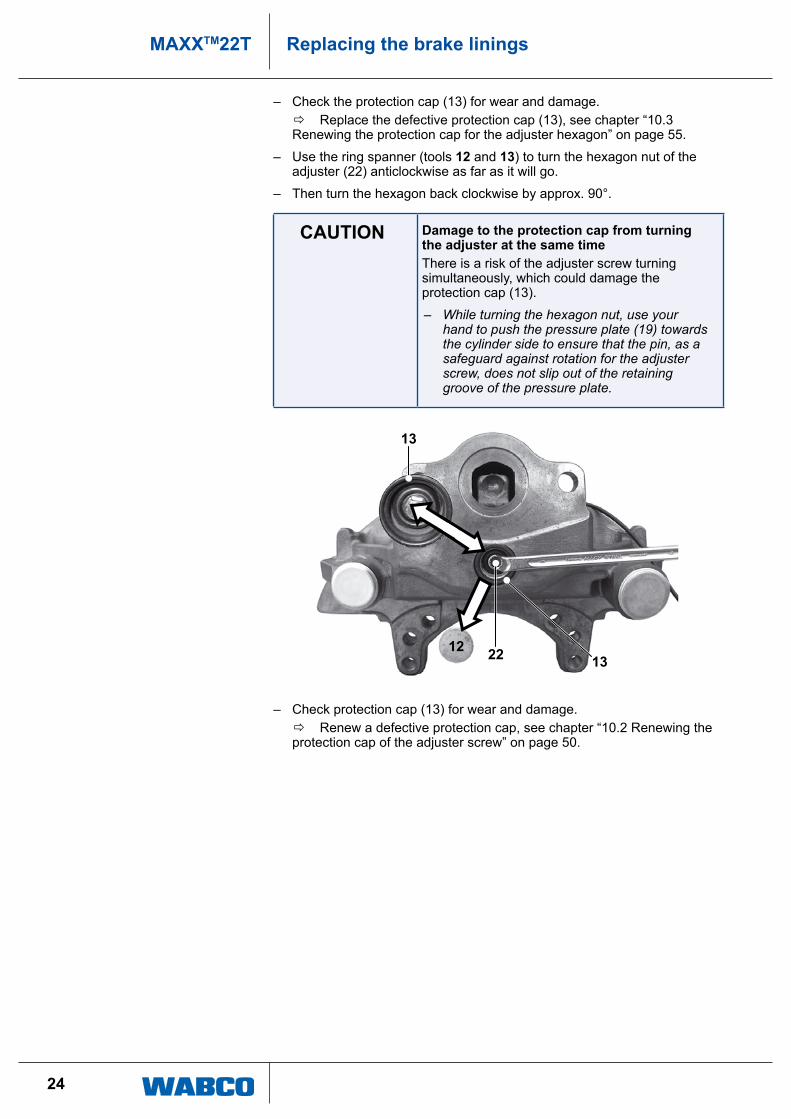
– check the protection cap (13) for wear and damage. Ö replace the defective protection cap (13), see chapter “10.3
renewing the protection cap for the adjuster hexagon” on page 55.
– use the ring spanner (tools 12 and 13) to turn the hexagon nut of the adjuster (22) anticlockwise as far as it will go.
– then turn the hexagon back clockwise by approx. 90°.
CAUTION Damage to the protection cap from turning the adjuster at the same timethere is a risk of the adjuster screw turning simultaneously, which could damage the protection cap (13).
– While turning the hexagon nut, use your hand to push the pressure plate (19) towards the cylinder side to ensure that the pin, as a safeguard against rotation for the adjuster screw, does not slip out of the retaining groove of the pressure plate.
132212
13
– check protection cap (13) for wear and damage. Ö renew a defective protection cap, see chapter “10.2 renewing the
protection cap of the adjuster screw” on page 50.
25
MAXXTM22TReplacing the brake linings
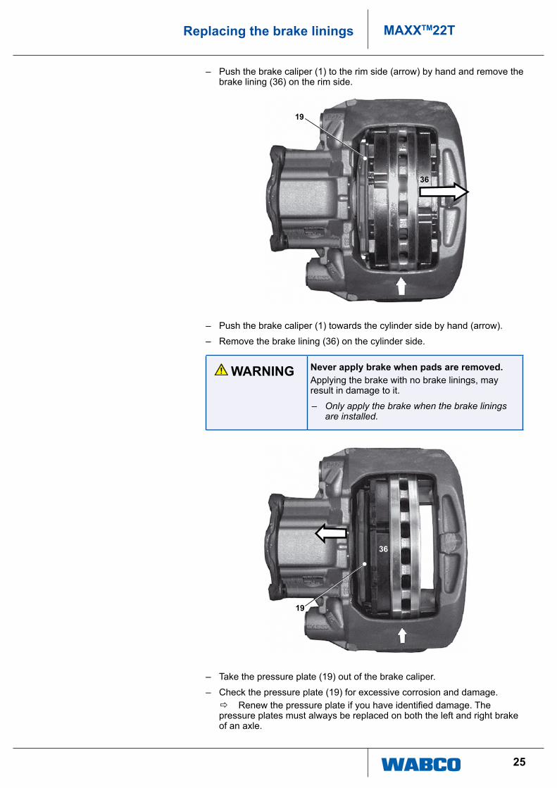
– push the brake caliper (1) to the rim side (arrow) by hand and remove the brake lining (36) on the rim side.
36
19
– push the brake caliper (1) towards the cylinder side by hand (arrow).
– remove the brake lining (36) on the cylinder side.
WARNING Never apply brake when pads are removed.applying the brake with no brake linings, may result in damage to it.
– Only apply the brake when the brake linings are installed.
36
19
– take the pressure plate (19) out of the brake caliper.
– check the pressure plate (19) for excessive corrosion and damage. Ö Renew the pressure plate if you have identified damage. The
pressure plates must always be replaced on both the left and right brake of an axle.
26
MAXXTM22T Replacing the brake linings
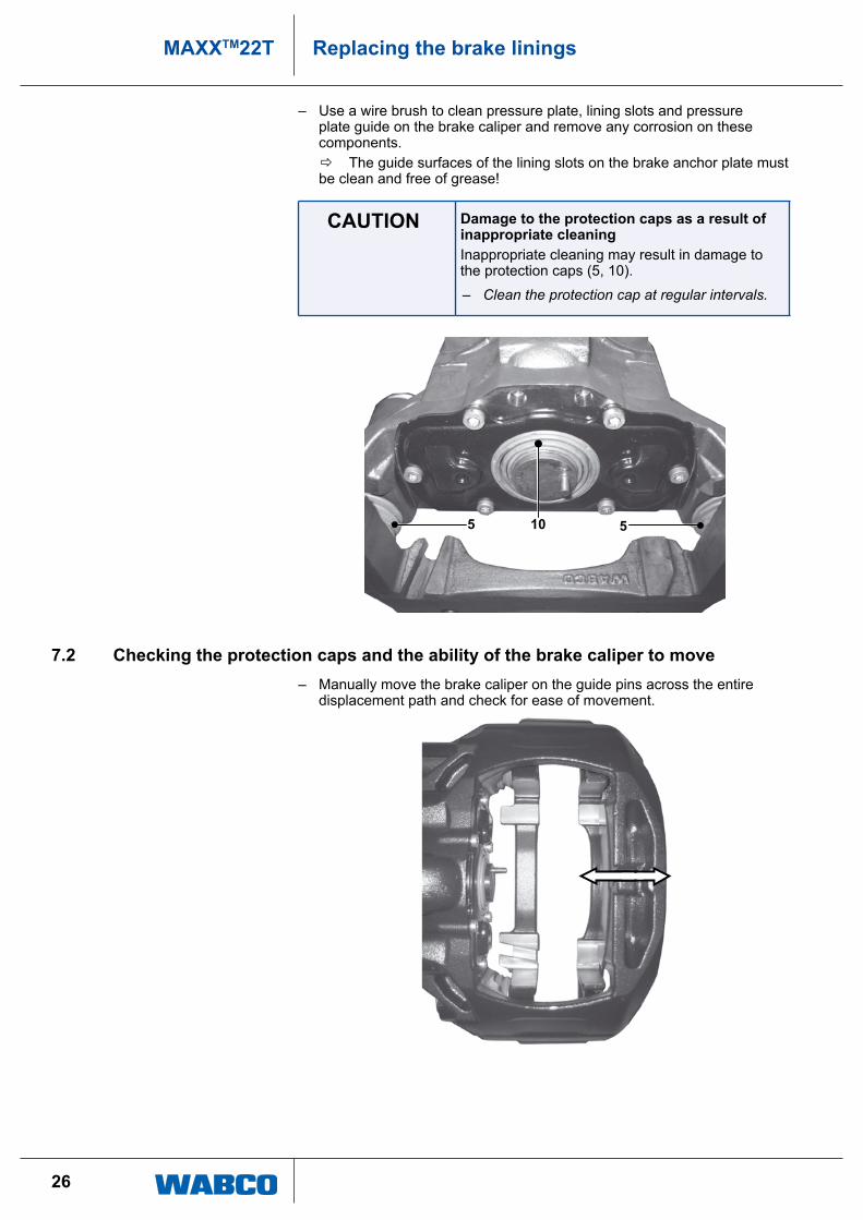
– use a wire brush to clean pressure plate, lining slots and pressure plate guide on the brake caliper and remove any corrosion on these components.
Ö the guide surfaces of the lining slots on the brake anchor plate must be clean and free of grease!
CAUTION Damage to the protection caps as a result of inappropriate cleaninginappropriate cleaning may result in damage to the protection caps (5, 10).
– Clean the protection cap at regular intervals.
5 510
7.2 Checking the protection caps and the ability of the brake caliper to move – Manually move the brake caliper on the guide pins across the entire
displacement path and check for ease of movement.
27
MAXXTM22TReplacing the brake linings
CAUTION Damage to the protection caps caused by the brake caliper movingthere is a risk from the brake caliper's movement of the protection caps (5, 10) of the guide pins becoming crushed against the brake anchor plate.
– Ensure that the protection caps of the guide pins are not crushed against the brake anchor plate.
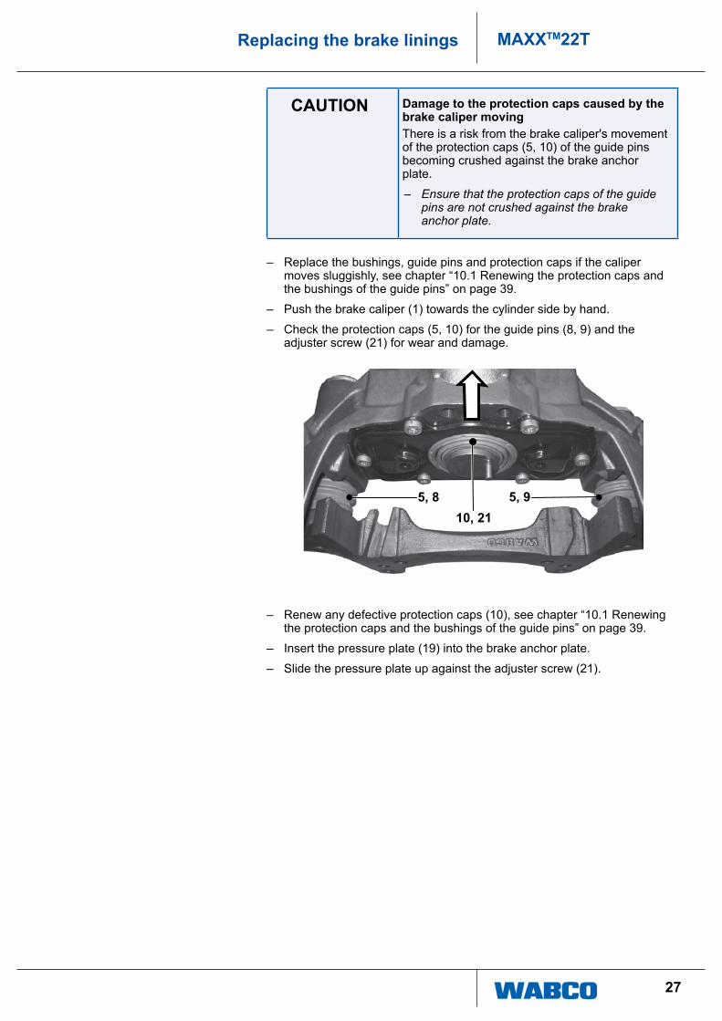
– replace the bushings, guide pins and protection caps if the caliper moves sluggishly, see chapter “10.1 renewing the protection caps and the bushings of the guide pins” on page 39.
– push the brake caliper (1) towards the cylinder side by hand.
– check the protection caps (5, 10) for the guide pins (8, 9) and the adjuster screw (21) for wear and damage.
5, 8 5, 910, 21
– renew any defective protection caps (10), see chapter “10.1 renewing the protection caps and the bushings of the guide pins” on page 39.
– insert the pressure plate (19) into the brake anchor plate.
– Slide the pressure plate up against the adjuster screw (21).
28
MAXXTM22T Replacing the brake linings
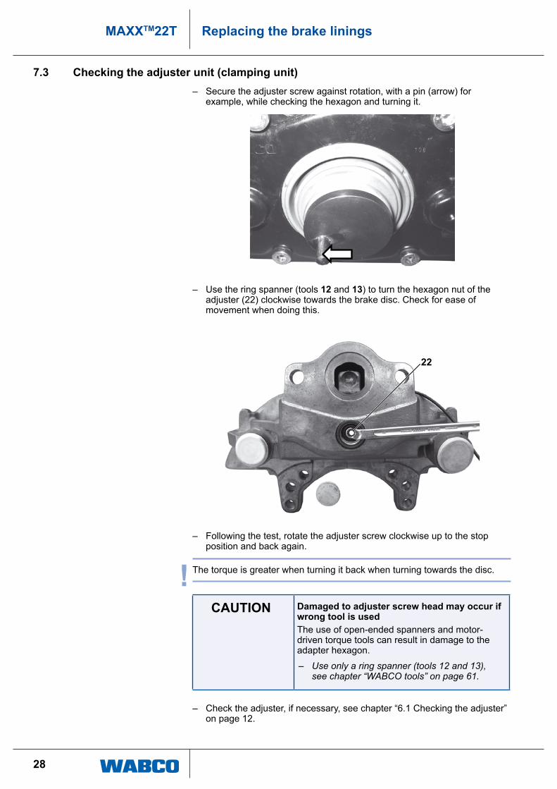
7.3 Checking the adjuster unit (clamping unit) – Secure the adjuster screw against rotation, with a pin (arrow) for
example, while checking the hexagon and turning it.
– use the ring spanner (tools 12 and 13) to turn the hexagon nut of the adjuster (22) clockwise towards the brake disc. check for ease of movement when doing this.
22
– Following the test, rotate the adjuster screw clockwise up to the stop position and back again.
! the torque is greater when turning it back when turning towards the disc.
CAUTION Damaged to adjuster screw head may occur if wrong tool is usedthe use of open-ended spanners and motor-driven torque tools can result in damage to the adapter hexagon.
– Use only a ring spanner (tools 12 and 13), see chapter “WABCO tools” on page 61.
– check the adjuster, if necessary, see chapter “6.1 checking the adjuster” on page 12.
29
MAXXTM22TReplacing the brake linings
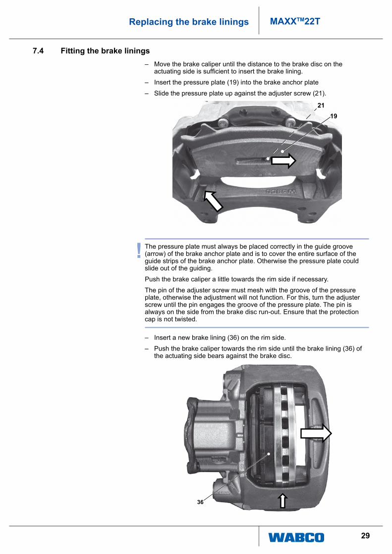
7.4 Fitting the brake linings – Move the brake caliper until the distance to the brake disc on the
actuating side is sufficient to insert the brake lining.
– insert the pressure plate (19) into the brake anchor plate
– Slide the pressure plate up against the adjuster screw (21).
1921
! the pressure plate must always be placed correctly in the guide groove (arrow) of the brake anchor plate and is to cover the entire surface of the guide strips of the brake anchor plate. otherwise the pressure plate could slide out of the guiding.
push the brake caliper a little towards the rim side if necessary.
the pin of the adjuster screw must mesh with the groove of the pressure plate, otherwise the adjustment will not function. For this, turn the adjuster screw until the pin engages the groove of the pressure plate. the pin is always on the side from the brake disc run-out. ensure that the protection cap is not twisted.
– insert a new brake lining (36) on the rim side.
– push the brake caliper towards the rim side until the brake lining (36) of the actuating side bears against the brake disc.
36
30
MAXXTM22T Replacing the brake linings
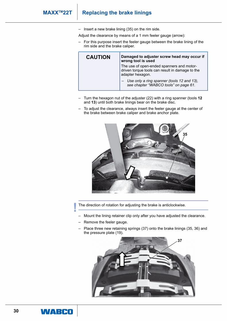
– insert a new brake lining (35) on the rim side.
adjust the clearance by means of a 1 mm feeler gauge (arrow):
– For this purpose insert the feeler gauge between the brake lining of the rim side and the brake caliper.
CAUTION Damaged to adjuster screw head may occur if wrong tool is usedthe use of open-ended spanners and motor-driven torque tools can result in damage to the adapter hexagon.
– Use only a ring spanner (tools 12 and 13), see chapter “WABCO tools” on page 61.
– turn the hexagon nut of the adjuster (22) with a ring spanner (tools 12 and 13) until both brake linings bear on the brake disc.
– to adjust the clearance, always insert the feeler gauge at the center of the brake between brake caliper and brake anchor plate.
35
! the direction of rotation for adjusting the brake is anticlockwise.
– Mount the lining retainer clip only after you have adjusted the clearance.
– remove the feeler gauge.
– place three new retaining springs (37) onto the brake linings (35, 36) and the pressure plate (19).
37

31
MAXXTM22TReplacing the brake linings
– push a new lining retainer clip (38) through the openings (arrows) in the cable guide plate into the openings of the brake caliper and press these down so that the radial lugs of the retaining springs engage into the clip.
38
– Fasten the new hexagon screw (39) to the brake caliper with the specified torque.
39
32
MAXXTM22T Replacing the brake linings
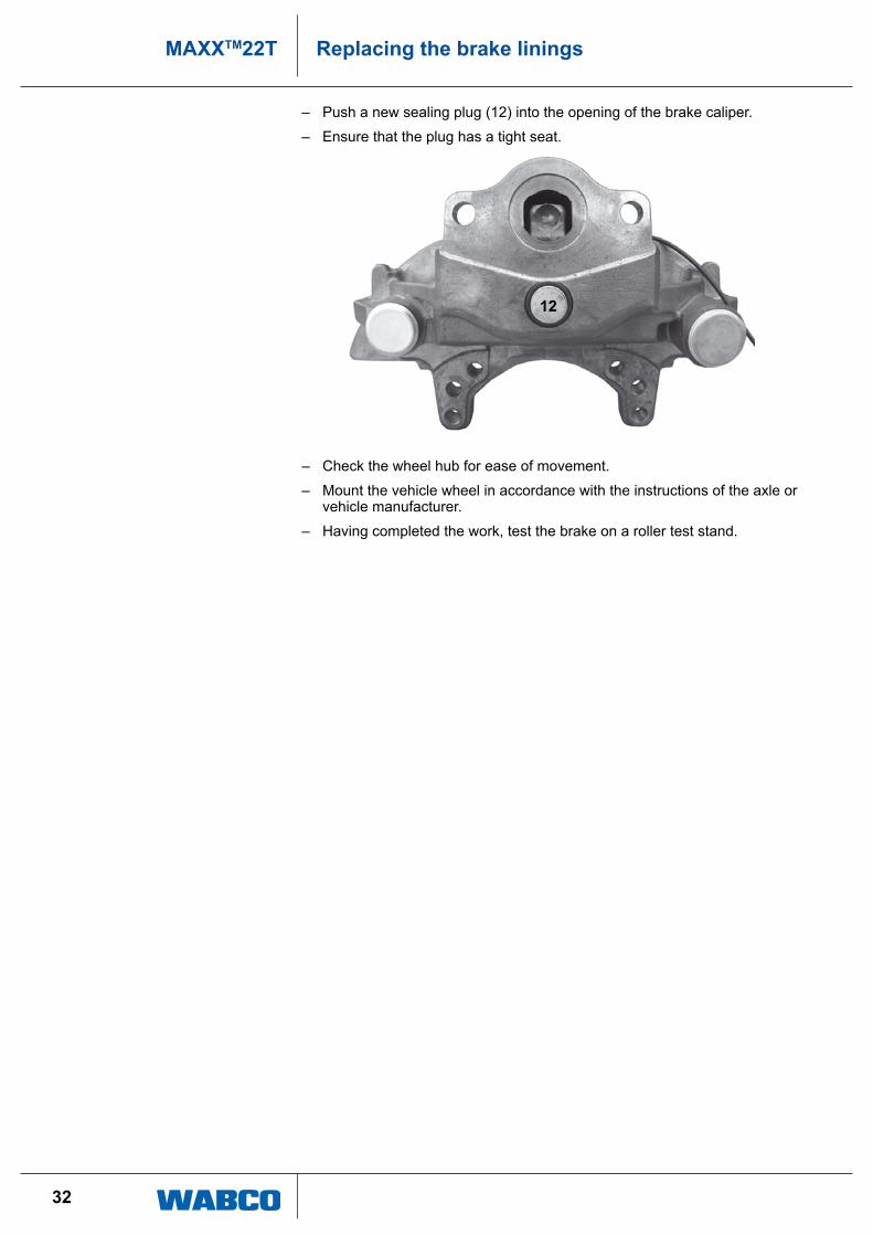
– push a new sealing plug (12) into the opening of the brake caliper.
– ensure that the plug has a tight seat.
12
– check the wheel hub for ease of movement.
– Mount the vehicle wheel in accordance with the instructions of the axle or vehicle manufacturer.
– having completed the work, test the brake on a roller test stand.
33
MAXXTM22TReplacing the brake cylinder
8 Replacing the brake cylinder
! observe all safety instructions, see chapter “3 Safety instructions” on page 6. these instructions must be observed to avoid personal injury and/or material damage.
Only use brake cylinders as specified by the axle or vehicle manufacturer.
the instructions for breaking the brake cylinder in are for general information. Pay attention to the installation specifications and the test and installation instructions of the brake cylinder manufacturer and strictly adhere to them.
the illustrations are for example only and may deviate from the actual design.
8.1 Removing the brake cylinder
CAUTION Remove air to vehicle before starting work – Make sure that the air connection lines have
been removed before removing chamber.
– unscrew the air connection from the brake cylinder according to the manufacturer's specifications.
– unscrew the brake cylinder nuts, see chapter “11.1 tools, spanner widths and tightening torques” on page 60, item Vii.
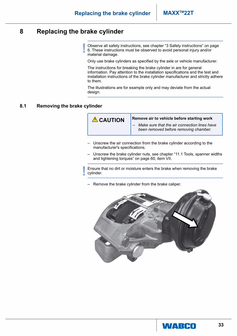
! ensure that no dirt or moisture enters the brake when removing the brake cylinder.
– remove the brake cylinder from the brake caliper.

34
MAXXTM22T Replacing the brake cylinder
8.2 Installing the brake cylinder
! depending on the installation position of the brake, ensure that the lower drainage aperture of the brake cylinder facing the ground is open.
Depending on the cylinder type and specifications of the cylinder manufacturer, the other apertures can either remain open or must by sealed by means of plugs.
ensure that no dirt or moisture enters the brake when cleaning.
– Clean the sealing surface (A) and flange area (B) of the brake caliper.
– Before attaching the brake cylinder, grease the calotte (c) in the brake lever.
B
C
A
– place the brake cylinder onto the brake caliper.
– use a spanner to screw new fastening nuts onto the brake cylinder until the brake cylinder fully rests on the brake caliper. it is essential to observe the instructions, see chapter “11.1 tools, spanner widths and tightening torques” on page 60, item V.
CAUTION Damage to the brake lines if installed incorrectlydamage to the brake lines can occur if installed incorrectly or becomes bent or rubs up against other parts.
– Installed brake lines should be free of any twisting and rubbing up against other parts.
35
MAXXTM22TReplacing the brake cylinder
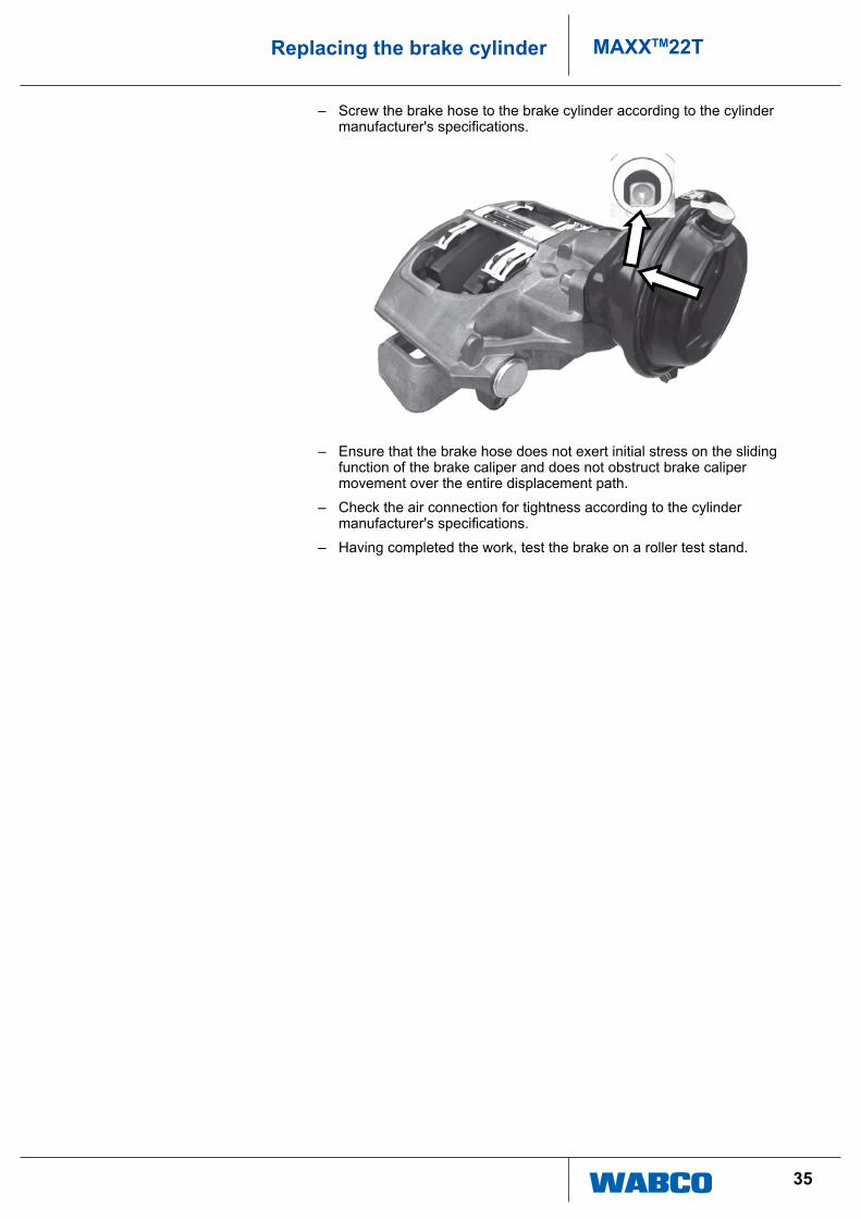
– Screw the brake hose to the brake cylinder according to the cylinder manufacturer's specifications.
– ensure that the brake hose does not exert initial stress on the sliding function of the brake caliper and does not obstruct brake caliper movement over the entire displacement path.
– check the air connection for tightness according to the cylinder manufacturer's specifications.
– having completed the work, test the brake on a roller test stand.
36
MAXXTM22T Renewing the brake
9 Renewing the brake
! observe all safety instructions, see chapter “3 Safety instructions” on page 6. these instructions must be observed to avoid personal injury and/or material damage.
the illustrations are for example only and may deviate from the actual design of the brake.
9.1 Removing the brake – remove the vehicle wheel in accordance with the instructions of the axle
or vehicle manufacturer.
– remove the brake cylinder from the brake caliper, see chapter “8.1 removing the brake cylinder” on page 33.
– remove the brake linings, see chapter “7.1 removing the brake linings” on page 22.
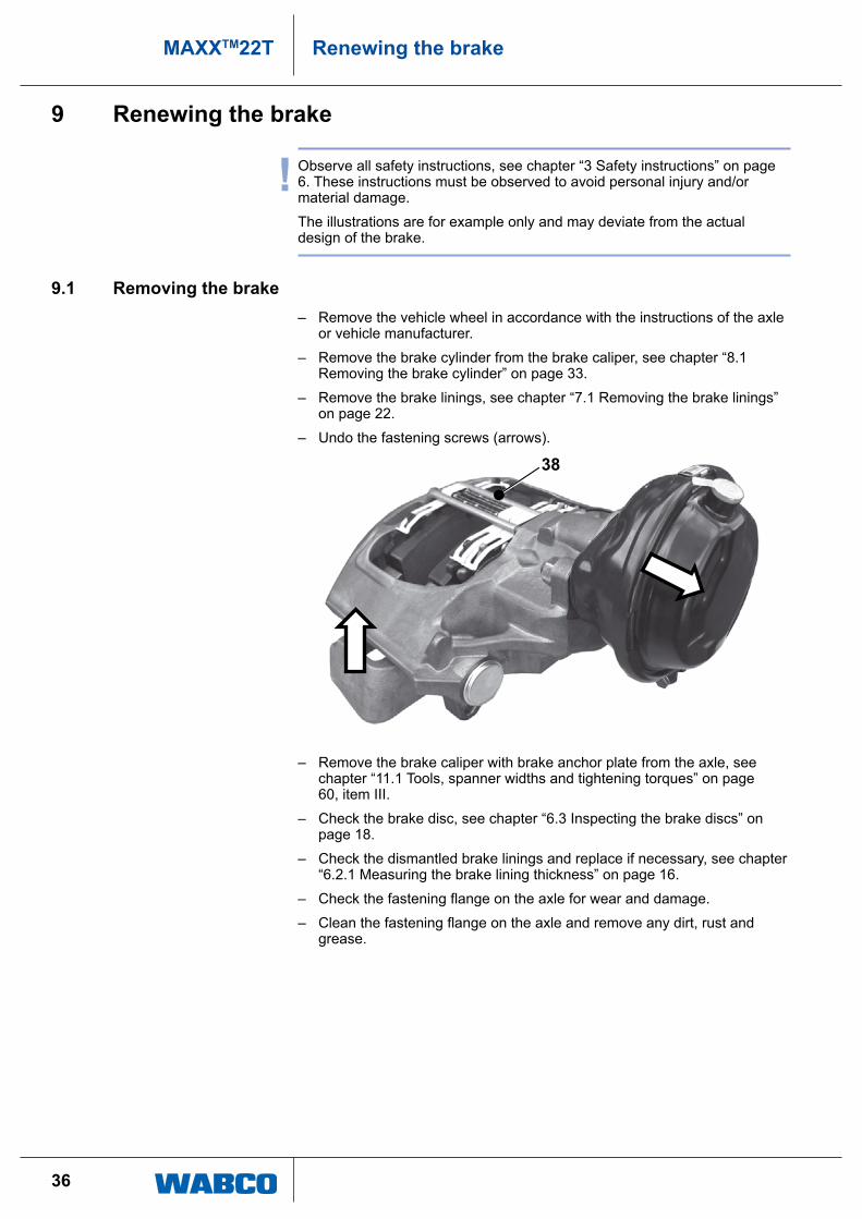
– undo the fastening screws (arrows).
38
– remove the brake caliper with brake anchor plate from the axle, see chapter “11.1 tools, spanner widths and tightening torques” on page 60, item iii.
– check the brake disc, see chapter “6.3 inspecting the brake discs” on page 18.
– check the dismantled brake linings and replace if necessary, see chapter “6.2.1 Measuring the brake lining thickness” on page 16.
– Check the fastening flange on the axle for wear and damage.
– Clean the fastening flange on the axle and remove any dirt, rust and grease.

37
MAXXTM22TRenewing the brake
9.2 Installing the brake
! the new brake without brake lining is supplied as a pre-assembled unit and may be mounted to the vehicle's axle via the brake anchor plate.
left and right brake must not be interchanged when they are installed on the axle. an arrow on the brake caliper indicates which brake is correct for the left and which for the right axle side. this arrow indicates the brake disc's direction of rotation during forward driving.
note the different versions of the brake on the front and rear axles.
– remove all transport locks from the new brake. Ö The protection film (arrow) or the transport protector cap must be
fully removed from the brake caliper in the area of the cylinder fastening.
– place the new brake with brake anchor plate on top of the brake disc and mount the brake onto the axle.
– tighten the bolts, see chapter “11.1 tools, spanner widths and tightening torques” on page 60, item iii.
! during this procedure, observe the assembly instructions of the axle of vehicle manufacturer with regard to bolt sizes, tightening torques, see chapter “11.1 tools, spanner widths and tightening torques” on page 60, item iii) and the tightening sequence for the fastening screws.
– install the pressure plate and brake linings.
38
MAXXTM22T Renewing the brake
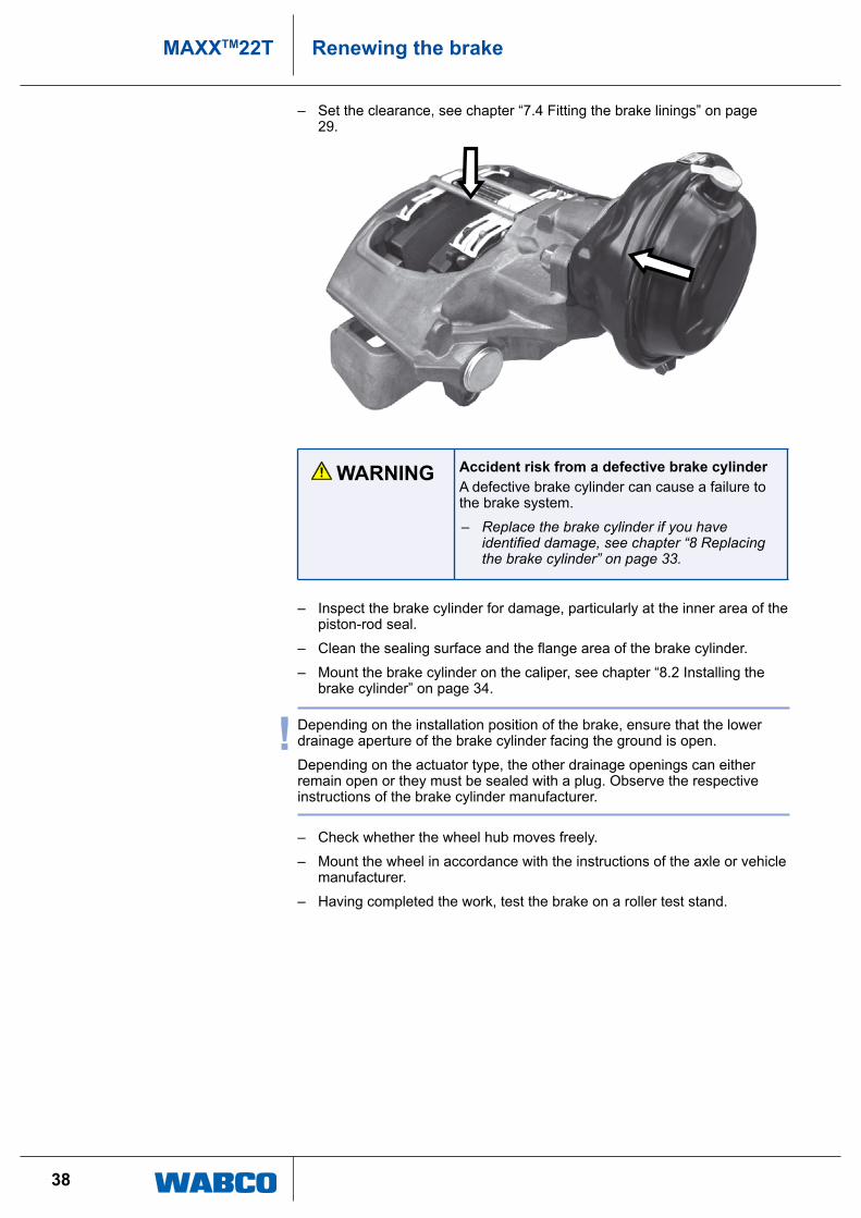
– Set the clearance, see chapter “7.4 Fitting the brake linings” on page 29.
WARNING Accident risk from a defective brake cylindera defective brake cylinder can cause a failure to the brake system.
– Replace the brake cylinder if you have identified damage, see chapter “8 Replacing the brake cylinder” on page 33.
– inspect the brake cylinder for damage, particularly at the inner area of the piston-rod seal.
– Clean the sealing surface and the flange area of the brake cylinder.
– Mount the brake cylinder on the caliper, see chapter “8.2 installing the brake cylinder” on page 34.
! depending on the installation position of the brake, ensure that the lower drainage aperture of the brake cylinder facing the ground is open.
depending on the actuator type, the other drainage openings can either remain open or they must be sealed with a plug. observe the respective instructions of the brake cylinder manufacturer.
– check whether the wheel hub moves freely.
– Mount the wheel in accordance with the instructions of the axle or vehicle manufacturer.
– having completed the work, test the brake on a roller test stand.
39
MAXXTM22TRenewing the seals
10 Renewing the seals
! observe all safety instructions, see chapter “3 Safety instructions” on page 6. these instructions must be observed to avoid personal injury and/or material damage.
if all seals of the brake caliper are replaced, the work sequences for renewing the protection caps and bushings of the guide pins, as well as the protection cap of the adjuster screw can be performed together.
if the seals were individually replaced however, the step sequences are to be performed individually as described in the sections below.
the illustrations are for example only and may deviate from the actual design.
10.1 Renewing the protection caps and the bushings of the guide pins
10.1.1 Disassembly – remove the vehicle wheel in accordance with the instructions of the axle
or vehicle manufacturer.
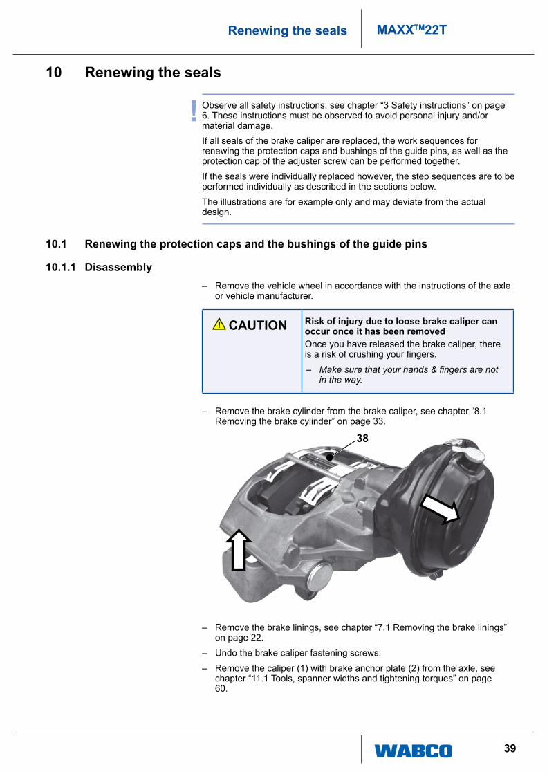
CAUTION Risk of injury due to loose brake caliper can occur once it has been removedonce you have released the brake caliper, there is a risk of crushing your fingers.
– Make sure that your hands & fingers are not in the way.
– remove the brake cylinder from the brake caliper, see chapter “8.1 removing the brake cylinder” on page 33.
38
– remove the brake linings, see chapter “7.1 removing the brake linings” on page 22.
– undo the brake caliper fastening screws.
– remove the caliper (1) with brake anchor plate (2) from the axle, see chapter “11.1 tools, spanner widths and tightening torques” on page 60.
40
MAXXTM22T Renewing the seals
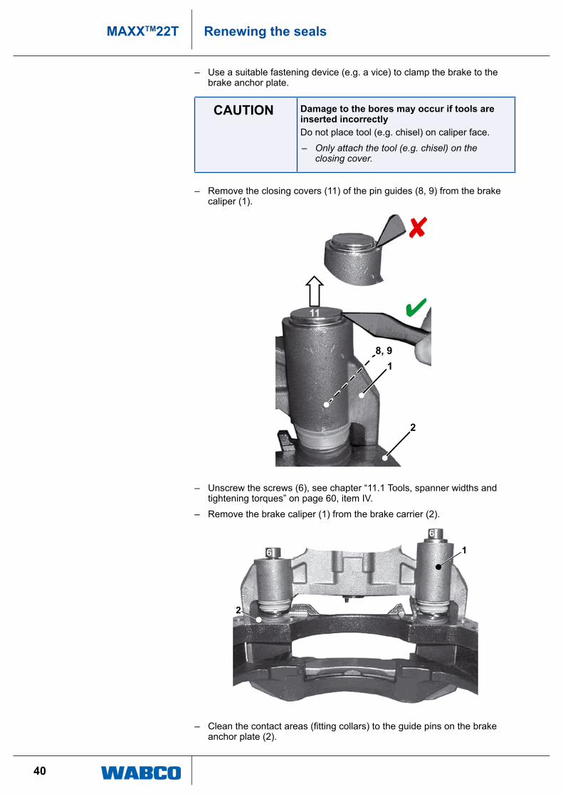
– use a suitable fastening device (e.g. a vice) to clamp the brake to the brake anchor plate.
CAUTION Damage to the bores may occur if tools are inserted incorrectlydo not place tool (e.g. chisel) on caliper face.
– Only attach the tool (e.g. chisel) on the closing cover.
– remove the closing covers (11) of the pin guides (8, 9) from the brake caliper (1).
11
8, 91
2
– unscrew the screws (6), see chapter “11.1 tools, spanner widths and tightening torques” on page 60, item iV.
– remove the brake caliper (1) from the brake carrier (2).
6
6
1
2
– Clean the contact areas (fitting collars) to the guide pins on the brake anchor plate (2).
41
MAXXTM22TRenewing the seals
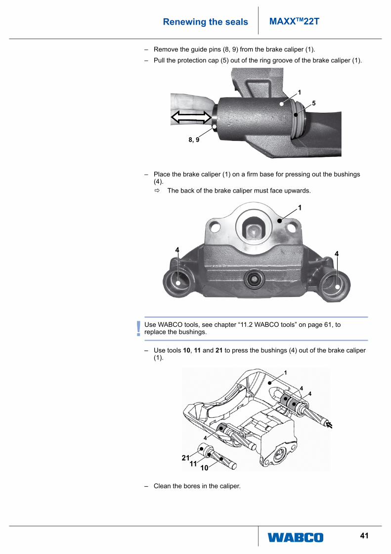
– remove the guide pins (8, 9) from the brake caliper (1).
– pull the protection cap (5) out of the ring groove of the brake caliper (1).
15
8, 9
– Place the brake caliper (1) on a firm base for pressing out the bushings (4).
Ö the back of the brake caliper must face upwards.
4 4
1
! use WaBco tools, see chapter “11.2 WaBco tools” on page 61, to replace the bushings.
– use tools 10, 11 and 21 to press the bushings (4) out of the brake caliper (1).
1
44
4
2111 10
– clean the bores in the caliper.

42
MAXXTM22T Renewing the seals
10.1.2 Assembly – press in two new bushings for the long guide pin.
– use tools 10, 11 and 29 to press the inner bushing into the bore of the brake caliper right to the end stop of the tool.
2911
10
– use tools 10, 11 and 22 to press the outer bushing into the same bore right to end stop of the tool.
221110
– grease the sliding surfaces of the bushings and the space between them.
– use tools 10, 11 and 26 to press a new bushing for the short guide pin into the bore of the brake caliper (1) right to the end stop of the tool.
2611
10

43
MAXXTM22TRenewing the seals
– grease the sliding surface of the bushing.
– clean the sealing seats (ring groove) of the brake caliper for the protection caps.
Ö the cleaned sealing seats must be clean and free from grease.
– Manually push two new protection caps (5) into the sealing seats (ring groove, arrow) of the brake caliper (1).
1
5
! Make sure that the protection caps (5) have an even and wrinkle-free seat in the seal seat of the brake caliper (1).
– grease the bearing surfaces of the guide pins (8, 9) and the beaded edge of the protection caps (5).
– insert the two new guide pins (8, 9) into the brake caliper (1) from the cylinder side.
58, 9
1
44
MAXXTM22T Renewing the seals
! The long guide bolt (8) is the fitting bolt and the short guide bolt (9) is the slider bolts.
note the differences in the brake versions. the positions of the guide bolts (8, 9) depends on the brake design and install situation.
This way, the fitting bolts (8) are on the entry side and on the exit side of the brake disc. the slider bolts (9) are then found on the opposite side.
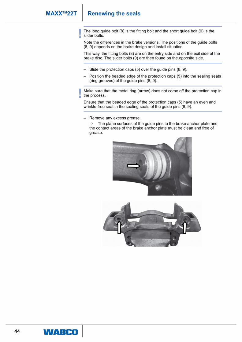
– Slide the protection caps (5) over the guide pins (8, 9).
– position the beaded edge of the protection caps (5) into the sealing seats (ring grooves) of the guide pins (8, 9).
! Make sure that the metal ring (arrow) does not come off the protection cap in the process.
ensure that the beaded edge of the protection caps (5) have an even and wrinkle-free seat in the sealing seats of the guide pins (8, 9).
– remove any excess grease. Ö the plane surfaces of the guide pins to the brake anchor plate and
the contact areas of the brake anchor plate must be clean and free of grease.
45
MAXXTM22TRenewing the seals
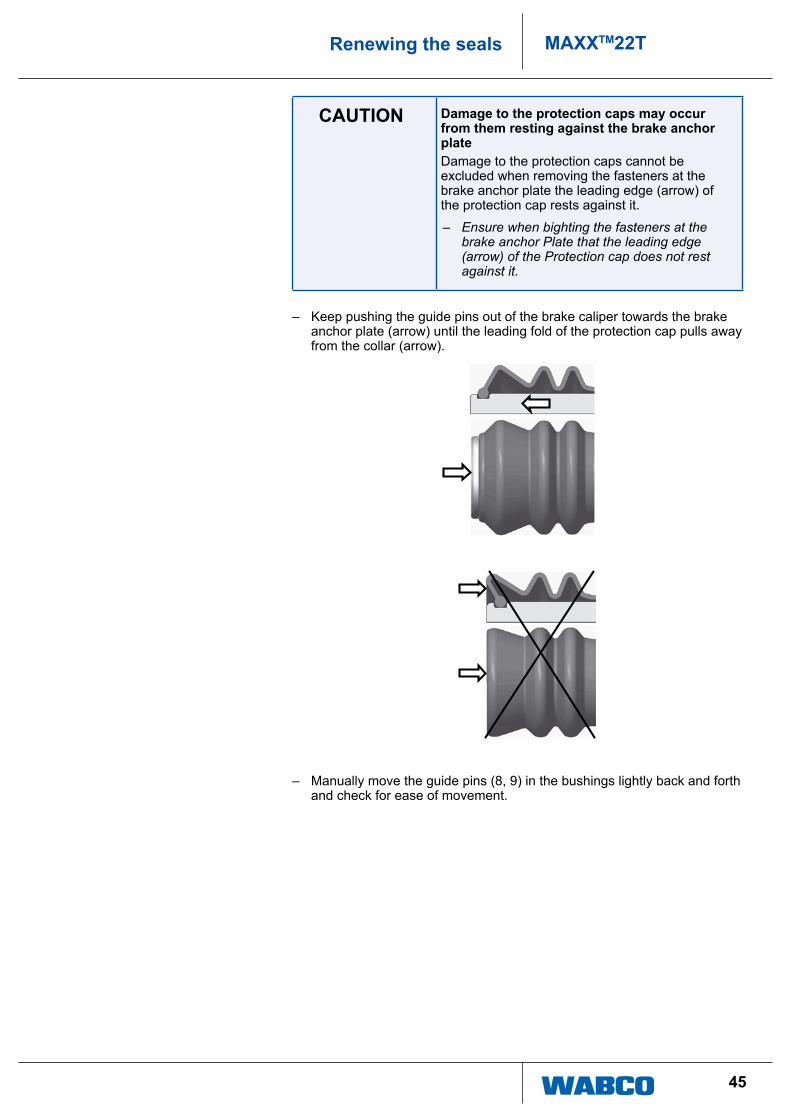
CAUTION Damage to the protection caps may occur from them resting against the brake anchor platedamage to the protection caps cannot be excluded when removing the fasteners at the brake anchor plate the leading edge (arrow) of the protection cap rests against it.
– Ensure when bighting the fasteners at the brake anchor Plate that the leading edge (arrow) of the Protection cap does not rest against it.
– keep pushing the guide pins out of the brake caliper towards the brake anchor plate (arrow) until the leading fold of the protection cap pulls away from the collar (arrow).
– Manually move the guide pins (8, 9) in the bushings lightly back and forth and check for ease of movement.
46
MAXXTM22T Renewing the seals
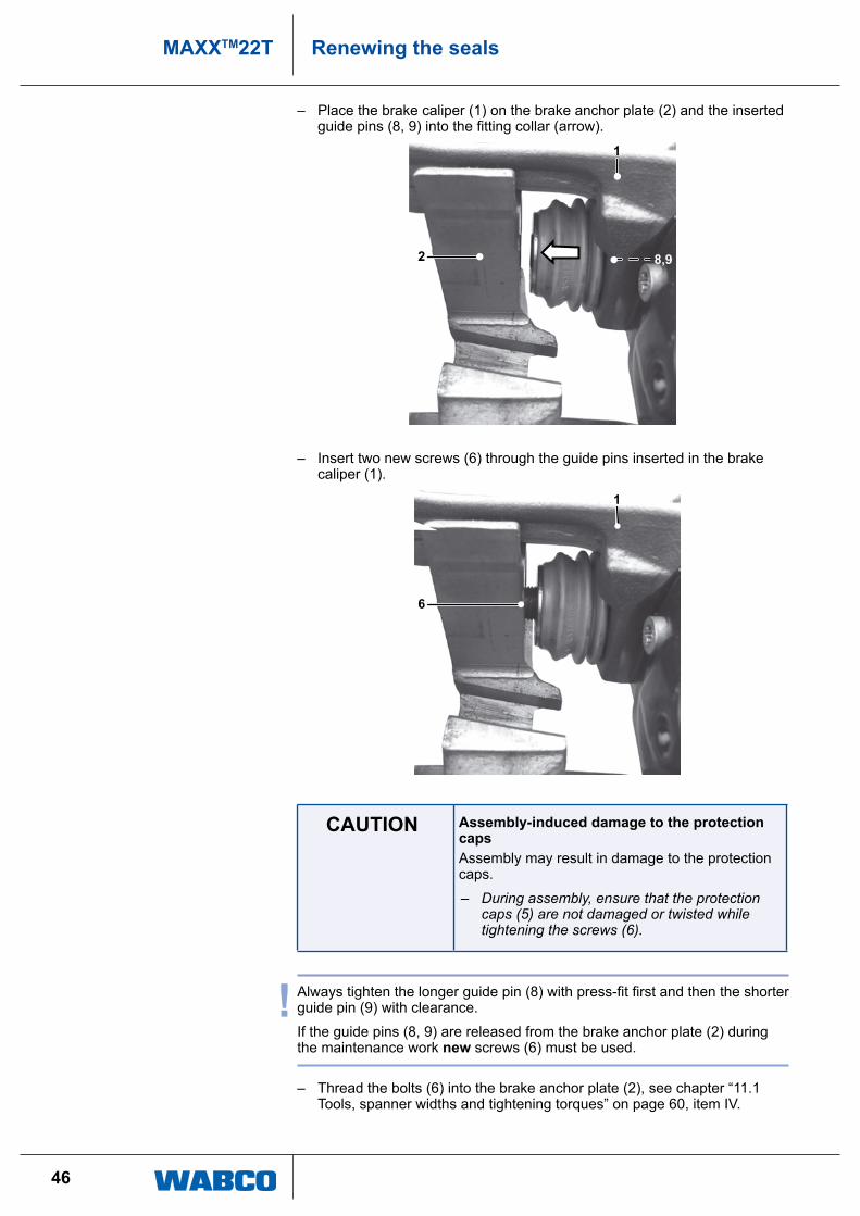
– place the brake caliper (1) on the brake anchor plate (2) and the inserted guide pins (8, 9) into the fitting collar (arrow).
8,92
1
– insert two new screws (6) through the guide pins inserted in the brake caliper (1).
6
1
CAUTION Assembly-induced damage to the protection capsassembly may result in damage to the protection caps.
– During assembly, ensure that the protection caps (5) are not damaged or twisted while tightening the screws (6).
! Always tighten the longer guide pin (8) with press-fit first and then the shorter guide pin (9) with clearance.
if the guide pins (8, 9) are released from the brake anchor plate (2) during the maintenance work new screws (6) must be used.
– thread the bolts (6) into the brake anchor plate (2), see chapter “11.1 tools, spanner widths and tightening torques” on page 60, item iV.
47
MAXXTM22TRenewing the seals
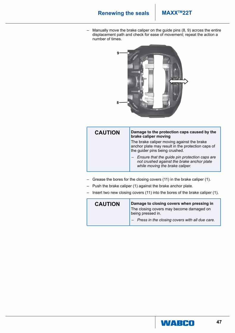
– Manually move the brake caliper on the guide pins (8, 9) across the entire displacement path and check for ease of movement; repeat the action a number of times.
9
8
CAUTION Damage to the protection caps caused by the brake caliper movingthe brake caliper moving against the brake anchor plate may result in the protection caps of the guider pins being crushed.
– Ensure that the guide pin protection caps are not crushed against the brake anchor plate while moving the brake caliper.
– grease the bores for the closing covers (11) in the brake caliper (1).
– push the brake caliper (1) against the brake anchor plate.
– insert two new closing covers (11) into the bores of the brake caliper (1).
CAUTION Damage to closing covers when pressing inthe closing covers may become damaged on being pressed in.
– Press in the closing covers with all due care.

48
MAXXTM22T Renewing the seals
– use tools 10, 11 and 27 to press the closing cover (11) down to the stop position.
1
11
2711 10
11
– Check the connecting surface on the fastening flange of the axle and the brake carrier and remove any dirt, rust or oil.
– place the brake with brake carrier over the brake disc.
– install the brake on the axle.
– tighten the bolts, see chapter “11.1 tools, spanner widths and tightening torques” on page 60, item iii.
! Always note the relevant specifications of the axle or vehicle manufacturer during this procedure and strictly adhere to them.
– install pressure plate and brake linings and adjust the clearance, see chapter “7.4 Fitting the brake linings” on page 29.
! ensure that no dirt or moisture enters the brake when cleaning.
49
MAXXTM22TRenewing the seals
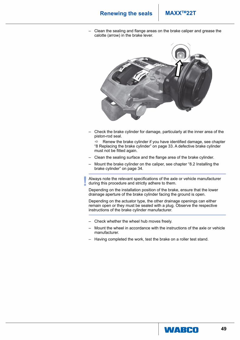
– Clean the sealing and flange areas on the brake caliper and grease the calotte (arrow) in the brake lever.
– check the brake cylinder for damage, particularly at the inner area of the piston-rod seal.
Ö Renew the brake cylinder if you have identified damage, see chapter “8 replacing the brake cylinder” on page 33. a defective brake cylinder must not be fitted again.
– Clean the sealing surface and the flange area of the brake cylinder.
– Mount the brake cylinder on the caliper, see chapter “8.2 installing the brake cylinder” on page 34.
! Always note the relevant specifications of the axle or vehicle manufacturer during this procedure and strictly adhere to them.
depending on the installation position of the brake, ensure that the lower drainage aperture of the brake cylinder facing the ground is open.
depending on the actuator type, the other drainage openings can either remain open or they must be sealed with a plug. observe the respective instructions of the brake cylinder manufacturer.
– check whether the wheel hub moves freely.
– Mount the wheel in accordance with the instructions of the axle or vehicle manufacturer.
– having completed the work, test the brake on a roller test stand.
50
MAXXTM22T Renewing the seals
10.2 Renewing the protection cap of the adjuster screw
! if the protection caps are removed individually, brake caliper and brake cylinder need not be dismantled.
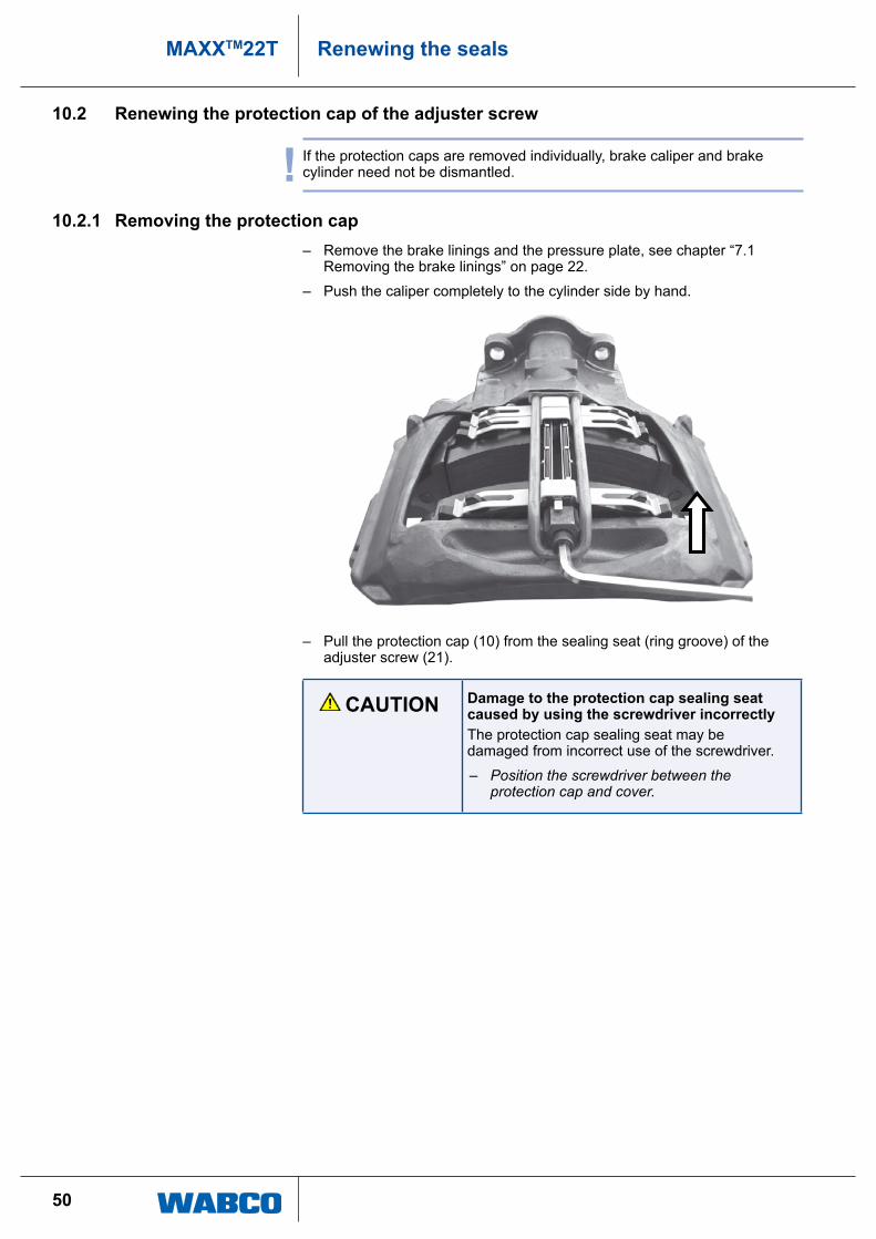
10.2.1 Removing the protection cap – remove the brake linings and the pressure plate, see chapter “7.1
removing the brake linings” on page 22.
– push the caliper completely to the cylinder side by hand.
– pull the protection cap (10) from the sealing seat (ring groove) of the adjuster screw (21).
CAUTION Damage to the protection cap sealing seat caused by using the screwdriver incorrectlythe protection cap sealing seat may be damaged from incorrect use of the screwdriver.
– Position the screwdriver between the protection cap and cover.
51
MAXXTM22TRenewing the seals
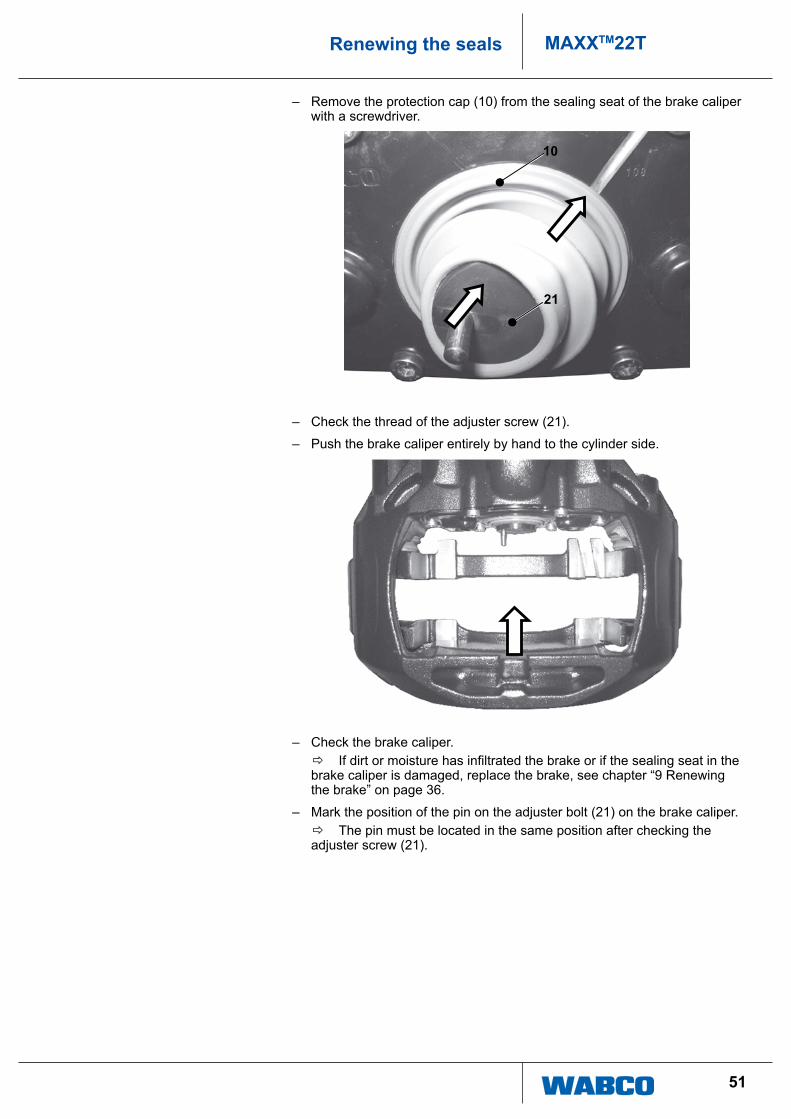
– remove the protection cap (10) from the sealing seat of the brake caliper with a screwdriver.
10
21
– check the thread of the adjuster screw (21).
– push the brake caliper entirely by hand to the cylinder side.
– check the brake caliper. Ö If dirt or moisture has infiltrated the brake or if the sealing seat in the
brake caliper is damaged, replace the brake, see chapter “9 renewing the brake” on page 36.
– Mark the position of the pin on the adjuster bolt (21) on the brake caliper. Ö the pin must be located in the same position after checking the
adjuster screw (21).
52
MAXXTM22T Renewing the seals
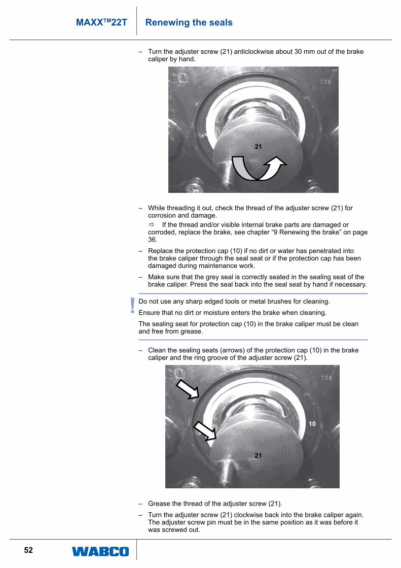
– turn the adjuster screw (21) anticlockwise about 30 mm out of the brake caliper by hand.
21
– While threading it out, check the thread of the adjuster screw (21) for corrosion and damage.
Ö if the thread and/or visible internal brake parts are damaged or corroded, replace the brake, see chapter “9 renewing the brake” on page 36.
– replace the protection cap (10) if no dirt or water has penetrated into the brake caliper through the seal seat or if the protection cap has been damaged during maintenance work.
– Make sure that the grey seal is correctly seated in the sealing seat of the brake caliper. press the seal back into the seal seat by hand if necessary.
! do not use any sharp edged tools or metal brushes for cleaning.
ensure that no dirt or moisture enters the brake when cleaning.
the sealing seat for protection cap (10) in the brake caliper must be clean and free from grease.
– clean the sealing seats (arrows) of the protection cap (10) in the brake caliper and the ring groove of the adjuster screw (21).
21
10
– grease the thread of the adjuster screw (21).
– turn the adjuster screw (21) clockwise back into the brake caliper again. the adjuster screw pin must be in the same position as it was before it was screwed out.
53
MAXXTM22TRenewing the seals
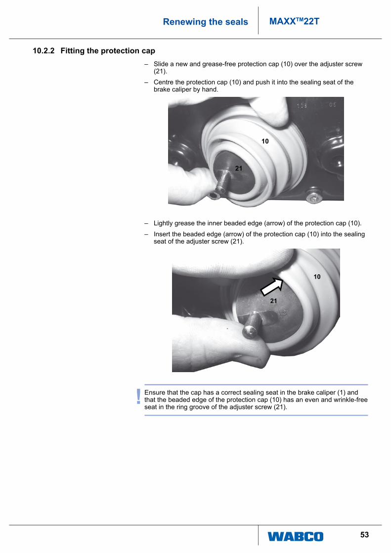
10.2.2 Fitting the protection cap – Slide a new and grease-free protection cap (10) over the adjuster screw
(21).
– centre the protection cap (10) and push it into the sealing seat of the brake caliper by hand.
10
21
– lightly grease the inner beaded edge (arrow) of the protection cap (10).
– insert the beaded edge (arrow) of the protection cap (10) into the sealing seat of the adjuster screw (21).
21
10
! ensure that the cap has a correct sealing seat in the brake caliper (1) and that the beaded edge of the protection cap (10) has an even and wrinkle-free seat in the ring groove of the adjuster screw (21).
54
MAXXTM22T Renewing the seals
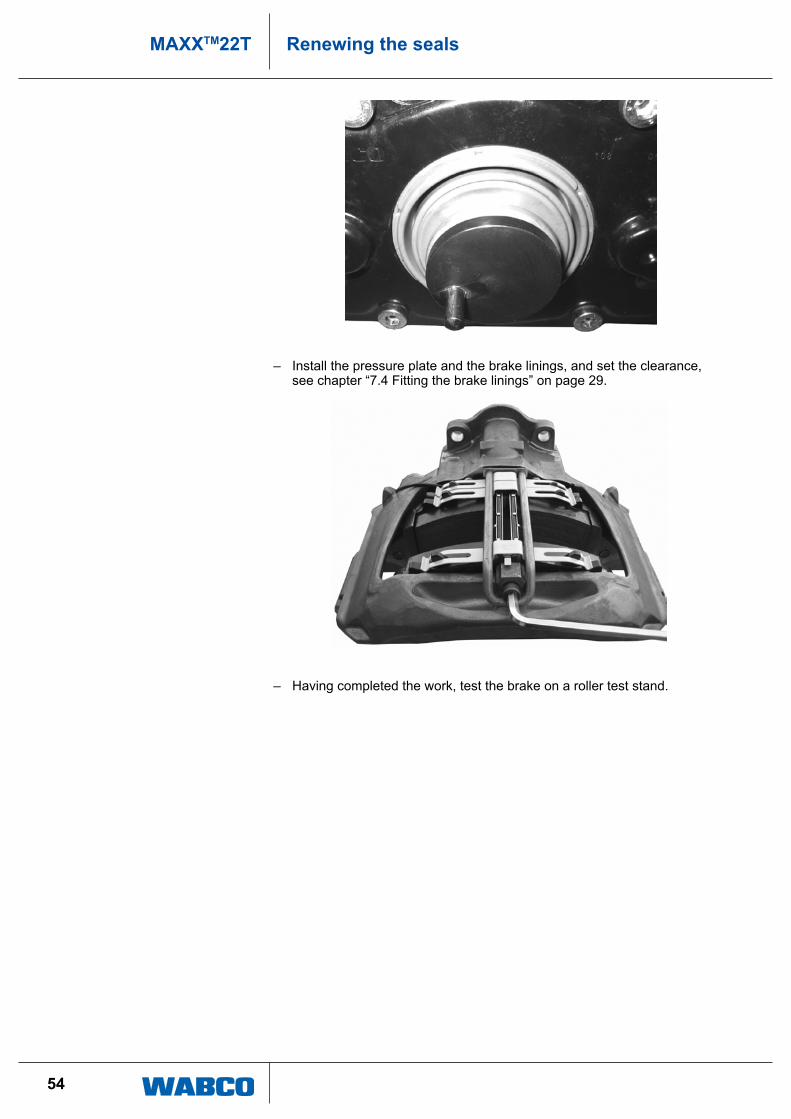
– install the pressure plate and the brake linings, and set the clearance, see chapter “7.4 Fitting the brake linings” on page 29.
– having completed the work, test the brake on a roller test stand.
55
MAXXTM22TRenewing the seals
10.3 Renewing the protection cap for the adjuster hexagon
! if the protection caps are removed individually, brake caliper and brake cylinder need not be dismantled.
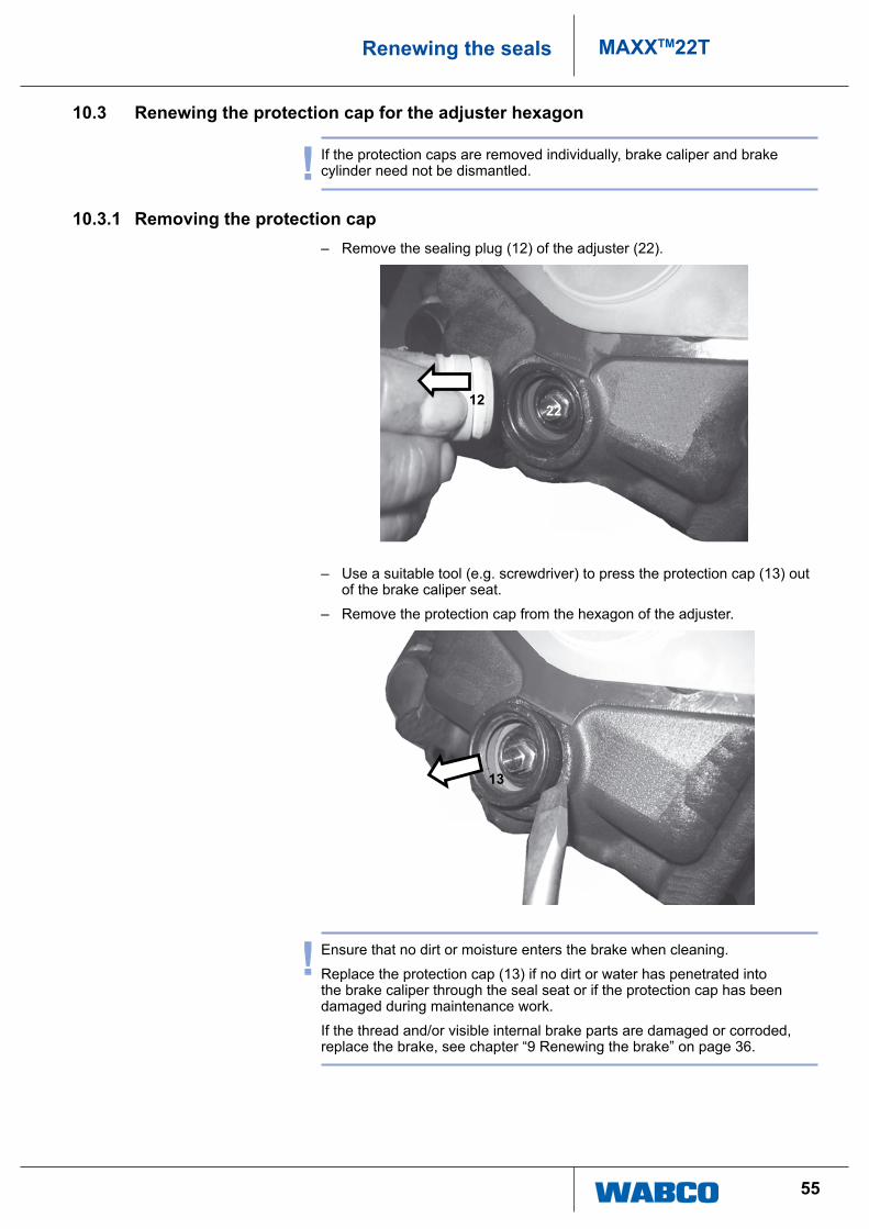
10.3.1 Removing the protection cap – remove the sealing plug (12) of the adjuster (22).
1222
– use a suitable tool (e.g. screwdriver) to press the protection cap (13) out of the brake caliper seat.
– remove the protection cap from the hexagon of the adjuster.
13
! ensure that no dirt or moisture enters the brake when cleaning.
replace the protection cap (13) if no dirt or water has penetrated into the brake caliper through the seal seat or if the protection cap has been damaged during maintenance work.
if the thread and/or visible internal brake parts are damaged or corroded, replace the brake, see chapter “9 renewing the brake” on page 36.
56
MAXXTM22T Renewing the seals
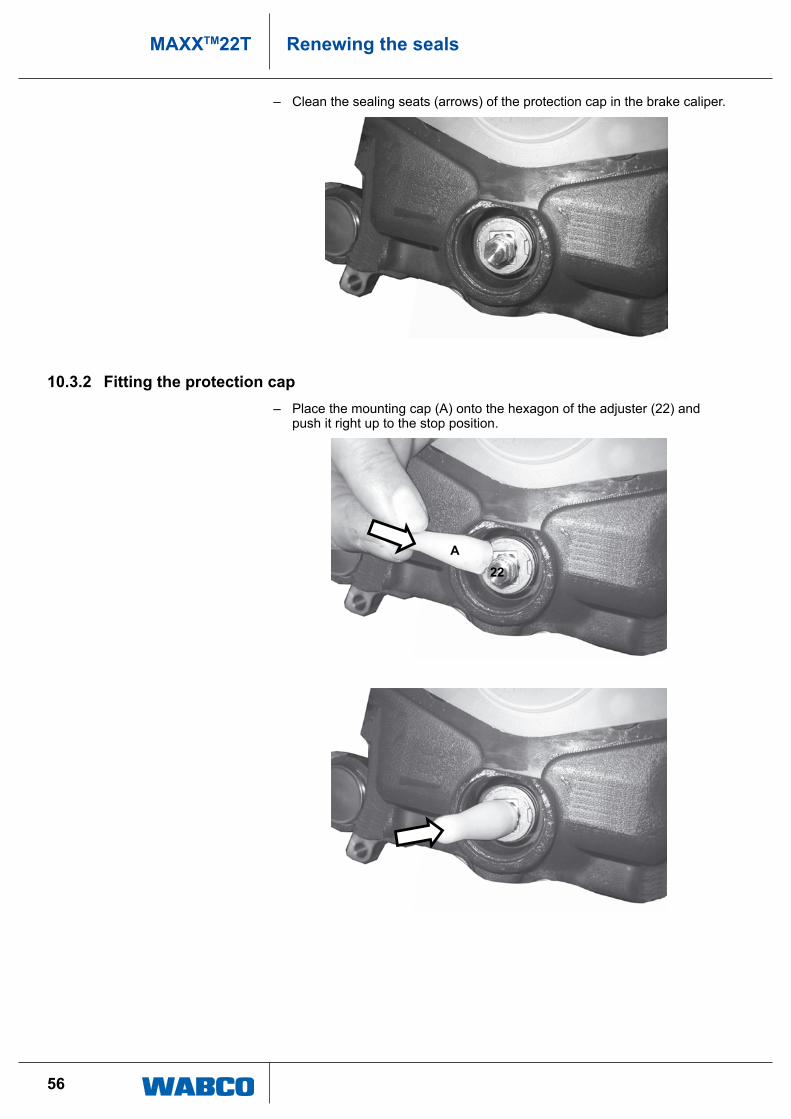
– clean the sealing seats (arrows) of the protection cap in the brake caliper.
10.3.2 Fitting the protection cap – place the mounting cap (a) onto the hexagon of the adjuster (22) and
push it right up to the stop position.
A22
57
MAXXTM22TRenewing the seals
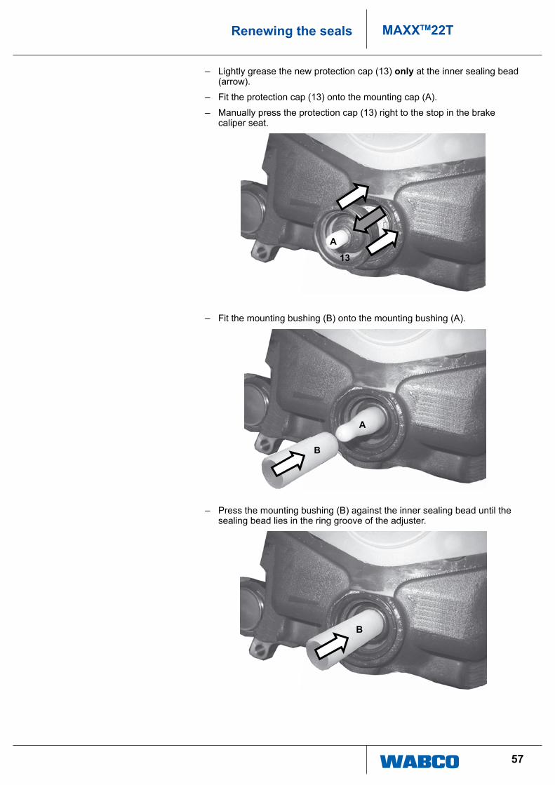
– lightly grease the new protection cap (13) only at the inner sealing bead (arrow).
– Fit the protection cap (13) onto the mounting cap (a).
– Manually press the protection cap (13) right to the stop in the brake caliper seat.
A
13
– Fit the mounting bushing (B) onto the mounting bushing (a).
A
B
– press the mounting bushing (B) against the inner sealing bead until the sealing bead lies in the ring groove of the adjuster.
B
58
MAXXTM22T Renewing the seals
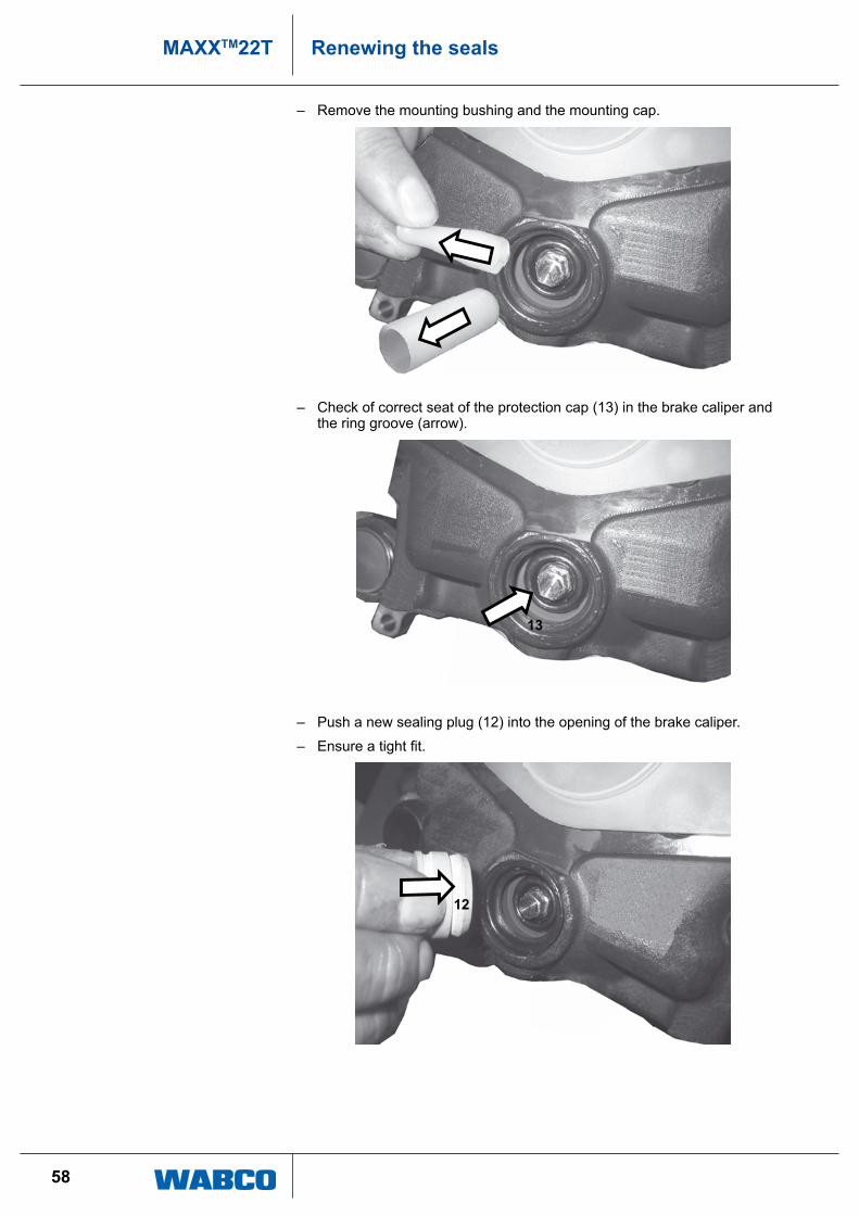
– remove the mounting bushing and the mounting cap.
– check of correct seat of the protection cap (13) in the brake caliper and the ring groove (arrow).
13
– push a new sealing plug (12) into the opening of the brake caliper.
– Ensure a tight fit.
12
59
MAXXTM22TRenewing the seals
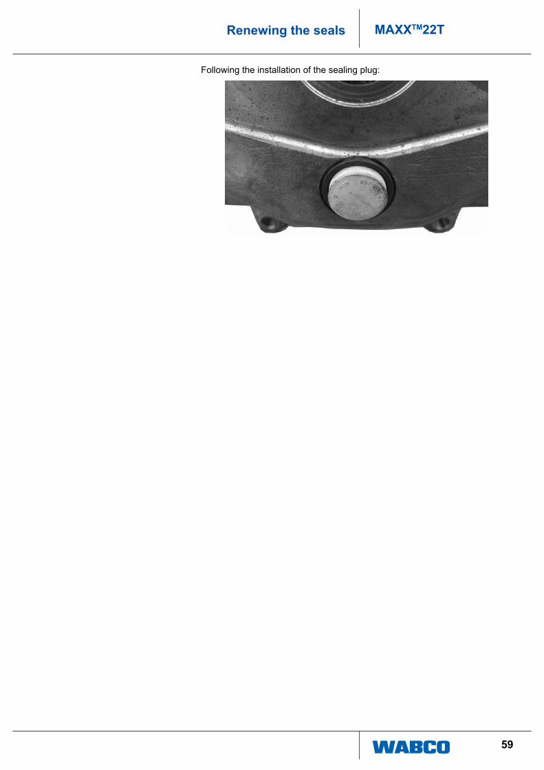
Following the installation of the sealing plug:
60
MAXXTM22T Annex
11 Annex
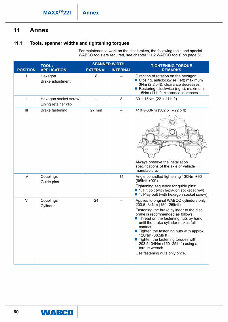
11.1 Tools, spanner widths and tightening torquesFor maintenance work on the disc brakes, the following tools and special WaBco tools are required, see chapter “11.2 WaBco tools” on page 61.
pOSITIONTOOL / AppLICATION
SpANNeR WIDTH TIGHTeNING TORqUe ReMARkSeXTeRNAL INTeRNAL
i hexagonBrake adjustment
8 – direction of rotation on the hexagon: � closing, anticlockwise (left) maximum 3nm (2.2lb·ft), clearance decreases.
� restoring, clockwise (right), maximum 15nm (11lb·ft, clearance increases.
ii hexagon socket screwlining retainer clip
– 8 30 + 15nm (22 + 11lb·ft)
iii Brake fastening 27 mm – 410+/-30nm (302.5 +/-22lb·ft)
always observe the installation specifications of the axle or vehicle manufacture.
iV couplingsguide pins
– 14 angle controlled tightening 130nm +90° (96lb·ft +90°) tightening sequence for guide pins: � 1. Fit bolt (with hexagon socket screw) � 1. play bolt (with hexagon socket screw)
V couplingscylinder
24 – applies to original WaBco cylinders only: 203.5 -34nm (150 -25lb·ft)Fastening the brake cylinder to the disc brake is recommended as follows: � thread on the fastening nuts by hand until the brake cylinder makes full contact.
� tighten the fastening nuts with approx. 120nm (88.5lb·ft).
� tighten the fastening torques with 203.5 -34nm (150 -25lb·ft) using a torque wrench.
use fastening nuts only once.
61
MAXXTM22TAnnex
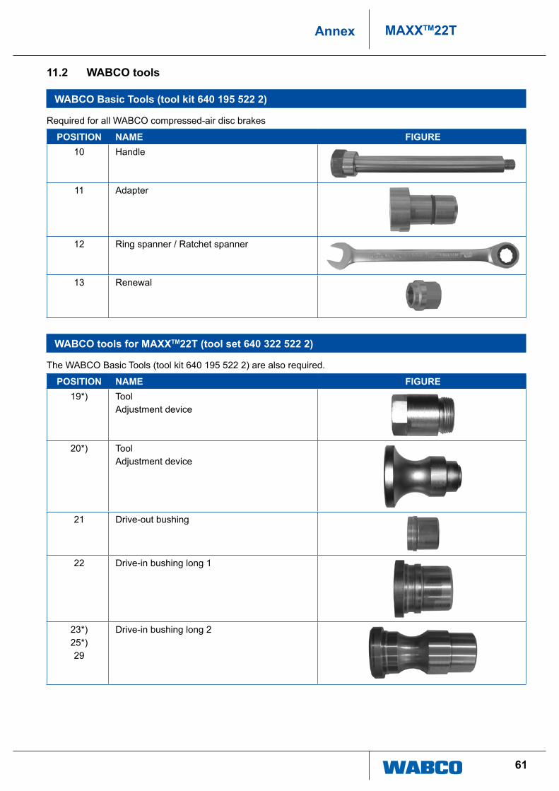
11.2 WABCO tools
WABCO Basic Tools (tool kit 640 195 522 2)
required for all WaBco compressed-air disc brakes
pOSITION NAMe FIGURe10 handle
11 adapter
12 ring spanner / ratchet spanner
13 renewal
WABCO tools for MAXXTM22T (tool set 640 322 522 2)
the WaBco Basic tools (tool kit 640 195 522 2) are also required.
pOSITION NAMe FIGURe19*) tool
adjustment device
20*) tooladjustment device
21 drive-out bushing
22 drive-in bushing long 1
23*)25*)29
drive-in bushing long 2

62
MAXXTM22T Annex
pOSITION NAMe FIGURe24*)26
drive-in bushing short
27 drive-in bushing long
*) these tools are part of the tool kit but are not required for brake type MaXXtM22t.
63
MAXXTM22TAnnex
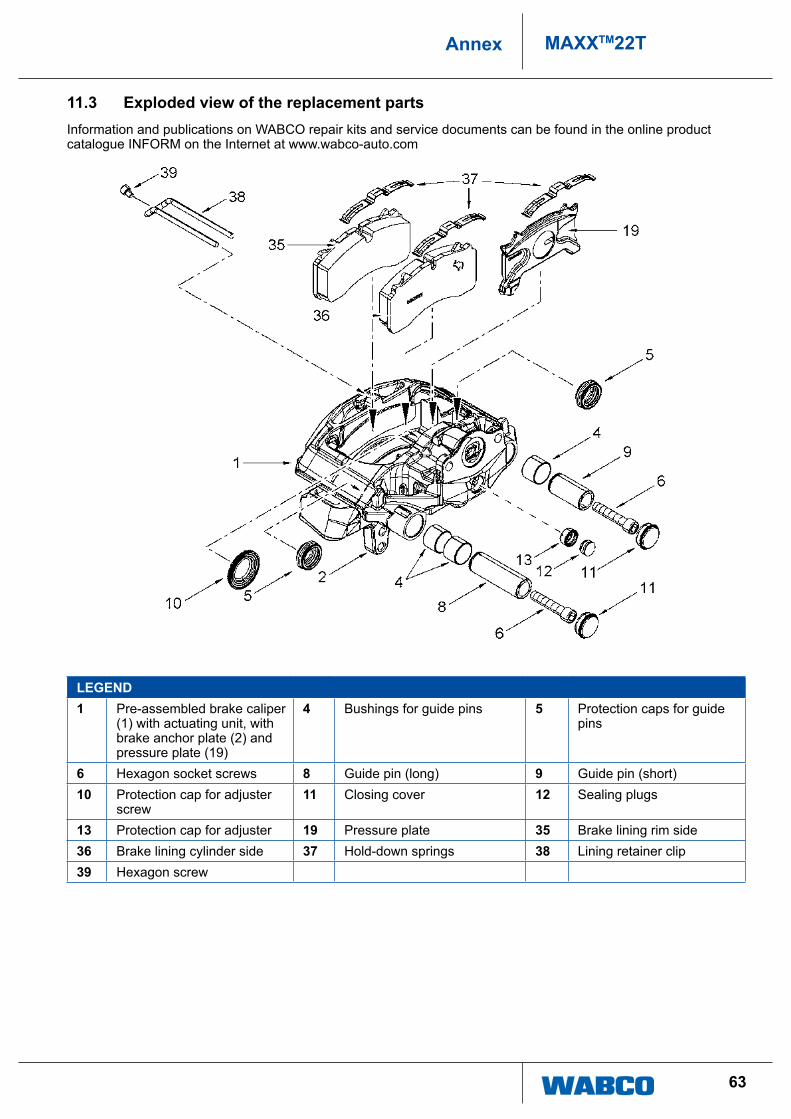
11.3 exploded view of the replacement partsinformation and publications on WaBco repair kits and service documents can be found in the online product catalogue inForM on the internet at www.wabco-auto.com
LeGeND1 pre-assembled brake caliper
(1) with actuating unit, with brake anchor plate (2) and pressure plate (19)
4 Bushings for guide pins 5 protection caps for guide pins
6 hexagon socket screws 8 guide pin (long) 9 guide pin (short)10 protection cap for adjuster
screw11 closing cover 12 Sealing plugs
13 protection cap for adjuster 19 pressure plate 35 Brake lining rim side36 Brake lining cylinder side 37 hold-down springs 38 lining retainer clip39 hexagon screw
64
MAXXTM22T Annex
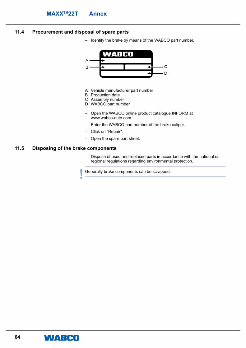
11.4 procurement and disposal of spare parts – identify the brake by means of the WaBco part number.
a Vehicle manufacturer part numberB production datec assembly numberd WaBco part number
– open the WaBco online product catalogue inForM at www.wabco-auto.com
– enter the WaBco part number of the brake caliper.
– click on "repair".
– open the spare part sheet.
11.5 Disposing of the brake components – dispose of used and replaced parts in accordance with the national or
regional regulations regarding environmental protection.
! generally brake components can be scrapped.

© 2
014
WA
BC
O E
urop
e B
VB
A –
All
right
s re
serv
ed –
815
220
216
3 /
10.2
014
and transmission automation systems supplied to the world’s leading commercial truck, bus and trailer manufacturers. With sales of $2.7 billion in 2013, WABCO is headquartered in Brussels, Belgium. For more information, visit
www.wabco-auto.com
WABCO (NYSE: WBC) is a leading global supplier of technologies and control systems for the safety and efficiency of commercial vehicles. Founded nearly 150 years ago, WABCO continues to pioneer breakthrough electronic, mechanical and mechatronic technologies for braking, stability