Embed Size (px)
Citation preview
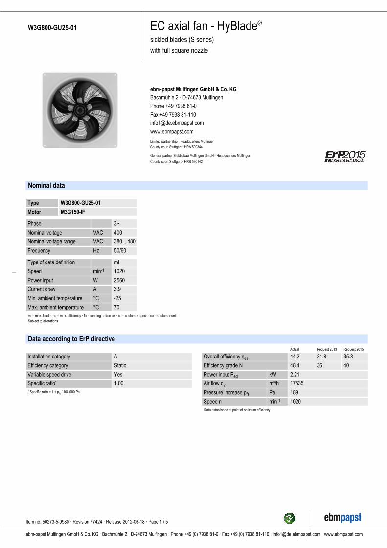
EC axial fan - HyBlade®
sickled blades (S series)
with full square nozzle
W3G800-GU25-01
ebm-papst Mulfingen GmbH & Co. KG
Bachmühle 2 · D-74673 Mulfingen
Phone +49 7938 81-0
Fax +49 7938 81-110
www.ebmpapst.com
Limited partnership · Headquarters Mulfingen
County court Stuttgart · HRA 590344
General partner Elektrobau Mulfingen GmbH · Headquarters Mulfingen
County court Stuttgart · HRB 590142
Nominal data
Type W3G800-GU25-01
Motor M3G150-IF
Phase 3~
Nominal voltage VAC 400
Nominal voltage range VAC 380 .. 480
Frequency Hz 50/60
Type of data definition ml
Speed min-1 1020
Power input W 2560
Current draw A 3.9
Min. ambient temperature °C -25
Max. ambient temperature °C 70ml = max. load · me = max. efficiency · fa = running at free air · cs = customer specs · cu = customer unitSubject to alterations
Data according to ErP directive
Installation category A
Efficiency category Static
Variable speed drive Yes
Specific ratio* 1.00* Specific ratio = 1 + pfs / 100 000 Pa
Actual Request 2013 Request 2015
Overall efficiency ηes 44.2 31.8 35.8
Efficiency grade N 48.4 36 40
Power input Ped kW 2.21
Air flow qv m³/h 17535
Pressure increase pfs Pa 189
Speed n min-1 1020Data established at point of optimum efficiency
Item no. 50273-5-9980 · Revision 77424 · Release 2012-06-18 · Page 1 / 5
ebm-papst Mulfingen GmbH & Co. KG · Bachmühle 2 · D-74673 Mulfingen · Phone +49 (0) 7938 81-0 · Fax +49 (0) 7938 81-110 · [email protected] · www.ebmpapst.com
EC axial fan - HyBlade®
sickled blades (S series)
with full square nozzle
W3G800-GU25-01
Technical features
Mass 45.8 kg
Size 800 mm
Surface of rotor Coated in black
Material of electronics housing Die-cast aluminium, coated in black
Material of blades Aluminium sheet insert, sprayed with PP plastic
Material of wall ring Sheet steel, pre-galvanised and coated in black plastic (RAL 9005)
Material of guard grille Steel, coated in black plastic (RAL9005)
Number of blades 5
Blade angle 0°
Direction of air flow "V"
Direction of rotation Clockwise, seen on rotor
Type of protection IP 54
Insulation class "F"
Humidity class F4-1
Max. permissible ambient motortemp. (transp./ storage)
+ 80 °C
Min. permissible ambient motortemp. (transp./storage)
- 40 °C
Mounting position Shaft horizontal or rotor on bottom; rotor on top on request
Condensate discharge holes Rotor-side
Operation mode S1
Motor bearing Ball bearing
Technical features - Output 10 VDC, max. 10 mA- Output 20 VDC, max. 50 mA- Output for slave 0-10 V- Operation and alarm display- Input for sensor 0-10 V or 4-20 mA- External 24 V input (programming)- External release input- Alarm relay- Integrated PID controller- Motor current limit- PFC, passive- RS485 MODBUS RTU- Soft start- Control input 0-10 VDC / PWM- Control interface with SELV potential safely disconnected from the mains- Over-temperature protected electronics / motor- Line undervoltage / phase failure detection
EMC interference immunity Acc. to EN 61000-6-2 (industrial environment)
EMC interference emission Acc. to EN 61000-6-3 (household environment)
Touch current acc. IEC 60990(measuring network Fig. 4, TNsystem)
<= 3.5 mA
Electrical leads Via terminal box
Motor protection Reverse polarity and locked-rotor protection
Protection class I (if protective earth is connected by customer)
Product conforming to standard EN 61800-5-1; CE
Approval GOST; UL 1004-7 + 60730; C22.2 Nr.77 + CAN/CSA-E60730-1
Item no. 50273-5-9980 · Revision 77424 · Release 2012-06-18 · Page 2 / 5
ebm-papst Mulfingen GmbH & Co. KG · Bachmühle 2 · D-74673 Mulfingen · Phone +49 (0) 7938 81-0 · Fax +49 (0) 7938 81-110 · [email protected] · www.ebmpapst.com
EC axial fan - HyBlade®
sickled blades (S series)
with full square nozzle
W3G800-GU25-01
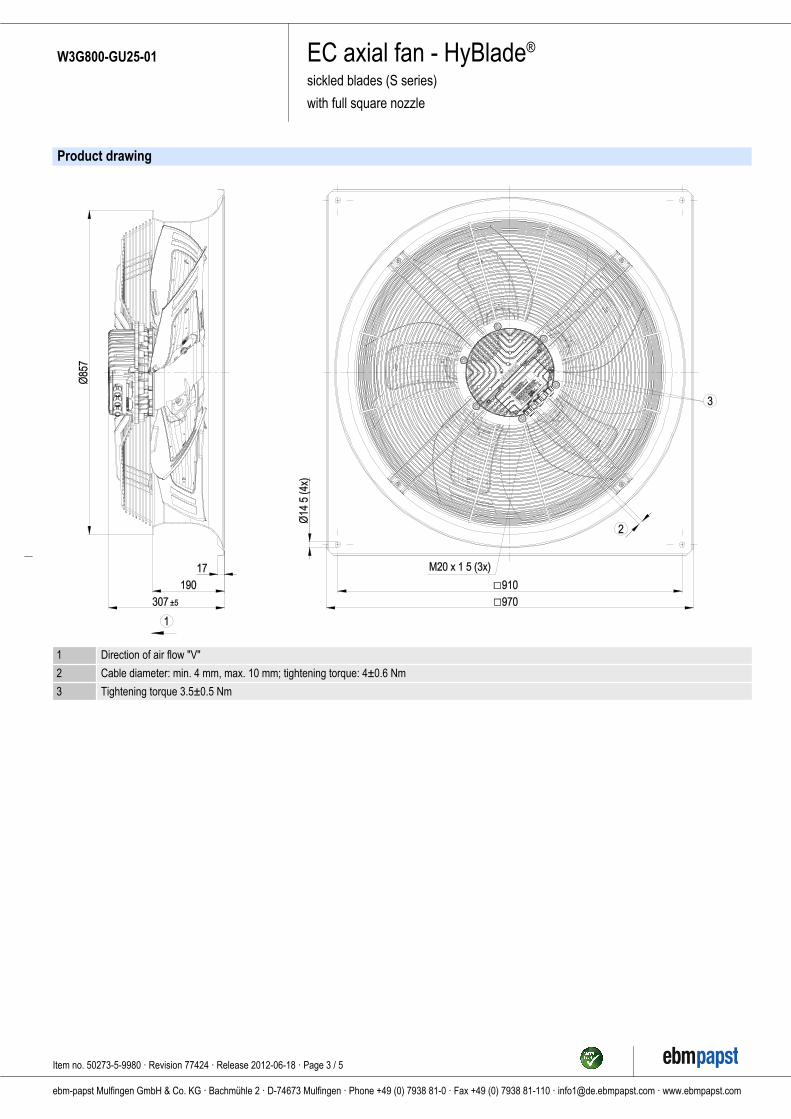
Product drawing
1 Direction of air flow "V"
2 Cable diameter: min. 4 mm, max. 10 mm; tightening torque: 4±0.6 Nm
3 Tightening torque 3.5±0.5 Nm
Item no. 50273-5-9980 · Revision 77424 · Release 2012-06-18 · Page 3 / 5
ebm-papst Mulfingen GmbH & Co. KG · Bachmühle 2 · D-74673 Mulfingen · Phone +49 (0) 7938 81-0 · Fax +49 (0) 7938 81-110 · [email protected] · www.ebmpapst.com
EC axial fan - HyBlade®
sickled blades (S series)
with full square nozzle
W3G800-GU25-01
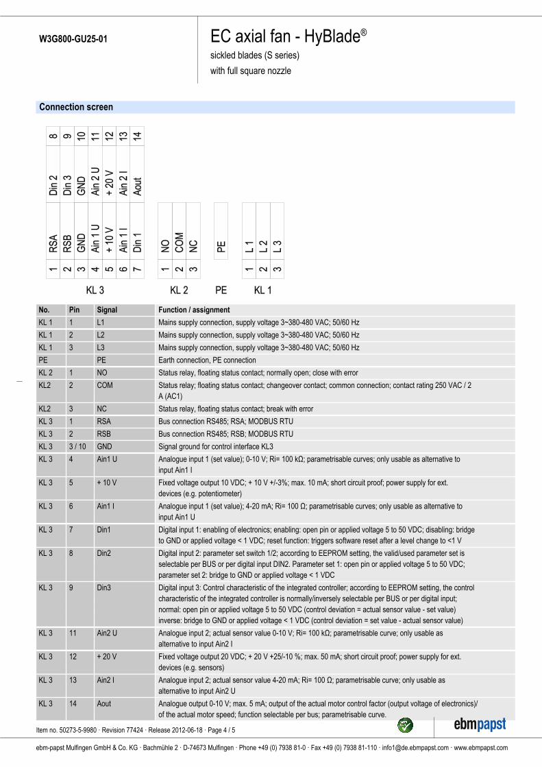
Connection screen
No. Pin Signal Function / assignment
KL 1 1 L1 Mains supply connection, supply voltage 3~380-480 VAC; 50/60 Hz
KL 1 2 L2 Mains supply connection, supply voltage 3~380-480 VAC; 50/60 Hz
KL 1 3 L3 Mains supply connection, supply voltage 3~380-480 VAC; 50/60 Hz
PE PE Earth connection, PE connection
KL 2 1 NO Status relay, floating status contact; normally open; close with error
KL2 2 COM Status relay; floating status contact; changeover contact; common connection; contact rating 250 VAC / 2A (AC1)
KL2 3 NC Status relay, floating status contact; break with error
KL 3 1 RSA Bus connection RS485; RSA; MODBUS RTU
KL 3 2 RSB Bus connection RS485; RSB; MODBUS RTU
KL 3 3 / 10 GND Signal ground for control interface KL3
KL 3 4 Ain1 U Analogue input 1 (set value); 0-10 V; Ri= 100 kΩ; parametrisable curves; only usable as alternative toinput Ain1 I
KL 3 5 + 10 V Fixed voltage output 10 VDC; + 10 V +/-3%; max. 10 mA; short circuit proof; power supply for ext.devices (e.g. potentiometer)
KL 3 6 Ain1 I Analogue input 1 (set value); 4-20 mA; Ri= 100 Ω; parametrisable curves; only usable as alternative toinput Ain1 U
KL 3 7 Din1 Digital input 1: enabling of electronics; enabling: open pin or applied voltage 5 to 50 VDC; disabling: bridgeto GND or applied voltage < 1 VDC; reset function: triggers software reset after a level change to <1 V
KL 3 8 Din2 Digital input 2: parameter set switch 1/2; according to EEPROM setting, the valid/used parameter set isselectable per BUS or per digital input DIN2. Parameter set 1: open pin or applied voltage 5 to 50 VDC;parameter set 2: bridge to GND or applied voltage < 1 VDC
KL 3 9 Din3 Digital input 3: Control characteristic of the integrated controller; according to EEPROM setting, the controlcharacteristic of the integrated controller is normally/inversely selectable per BUS or per digital input;normal: open pin or applied voltage 5 to 50 VDC (control deviation = actual sensor value - set value)inverse: bridge to GND or applied voltage < 1 VDC (control deviation = set value - actual sensor value)
KL 3 11 Ain2 U Analogue input 2; actual sensor value 0-10 V; Ri= 100 kΩ; parametrisable curve; only usable asalternative to input Ain2 I
KL 3 12 + 20 V Fixed voltage output 20 VDC; + 20 V +25/-10 %; max. 50 mA; short circuit proof; power supply for ext.devices (e.g. sensors)
KL 3 13 Ain2 I Analogue input 2; actual sensor value 4-20 mA; Ri= 100 Ω; parametrisable curve; only usable asalternative to input Ain2 U
KL 3 14 Aout Analogue output 0-10 V; max. 5 mA; output of the actual motor control factor (output voltage of electronics)/of the actual motor speed; function selectable per bus; parametrisable curve.
Item no. 50273-5-9980 · Revision 77424 · Release 2012-06-18 · Page 4 / 5
ebm-papst Mulfingen GmbH & Co. KG · Bachmühle 2 · D-74673 Mulfingen · Phone +49 (0) 7938 81-0 · Fax +49 (0) 7938 81-110 · [email protected] · www.ebmpapst.com
EC axial fan - HyBlade®
sickled blades (S series)
with full square nozzle
W3G800-GU25-01
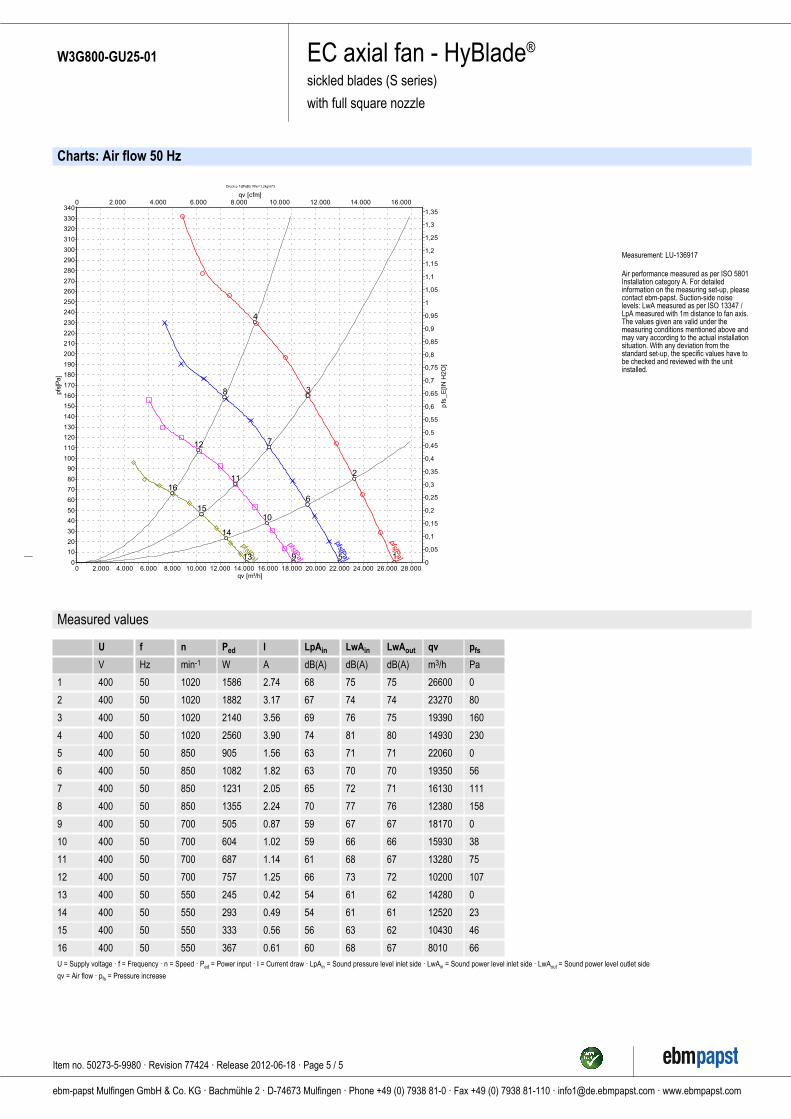
Charts: Air flow 50 Hz
Druck p f s[Pa]für Rho=1,2kg/m^3
qv [m³/h]28.00026.00024.00022.00020.00018.00016.00014.00012.00010.0008.0006.0004.0002.0000
qv [cfm]16.00014.00012.00010.0008.0006.0004.0002.0000
p fs[
Pa]
340
330
320
310
300
290
280
270
260
250
240
230
220
210
200
190
180
170
160
150
140
130
120
110
100
90
80
70
60
50
40
30
20
10
0
pfs
_E
[IN
H2O
]
1,35
1,3
1,25
1,2
1,15
1,1
1,05
1
0,95
0,9
0,85
0,8
0,75
0,7
0,65
0,6
0,55
0,5
0,45
0,4
0,35
0,3
0,25
0,2
0,15
0,1
0,05
0
p fs[Pa]
p fs[Pa]
p fs[Pa]
p fs[Pa] 1
2
3
4
5
6
7
8
9
10
11
12
13
14
15
16
Measurement: LU-136917
Air performance measured as per ISO 5801Installation category A. For detailedinformation on the measuring set-up, pleasecontact ebm-papst. Suction-side noiselevels: LwA measured as per ISO 13347 /LpA measured with 1m distance to fan axis.The values given are valid under themeasuring conditions mentioned above andmay vary according to the actual installationsituation. With any deviation from thestandard set-up, the specific values have tobe checked and reviewed with the unitinstalled.
Measured values
1
2
3
4
5
6
7
8
9
10
11
12
13
14
15
16
U
V
400
400
400
400
400
400
400
400
400
400
400
400
400
400
400
400
f
Hz
50
50
50
50
50
50
50
50
50
50
50
50
50
50
50
50
n
min-1
1020
1020
1020
1020
850
850
850
850
700
700
700
700
550
550
550
550
Ped
W
1586
1882
2140
2560
905
1082
1231
1355
505
604
687
757
245
293
333
367
I
A
2.74
3.17
3.56
3.90
1.56
1.82
2.05
2.24
0.87
1.02
1.14
1.25
0.42
0.49
0.56
0.61
LpAin
dB(A)
68
67
69
74
63
63
65
70
59
59
61
66
54
54
56
60
LwAin
dB(A)
75
74
76
81
71
70
72
77
67
66
68
73
61
61
63
68
LwAout
dB(A)
75
74
75
80
71
70
71
76
67
66
67
72
62
61
62
67
qv
m3/h
26600
23270
19390
14930
22060
19350
16130
12380
18170
15930
13280
10200
14280
12520
10430
8010
pfs
Pa
0
80
160
230
0
56
111
158
0
38
75
107
0
23
46
66
U = Supply voltage · f = Frequency · n = Speed · Ped = Power input · I = Current draw · LpAin = Sound pressure level inlet side · LwAin = Sound power level inlet side · LwAout = Sound power level outlet side
qv = Air flow · pfs = Pressure increase
Item no. 50273-5-9980 · Revision 77424 · Release 2012-06-18 · Page 5 / 5
ebm-papst Mulfingen GmbH & Co. KG · Bachmühle 2 · D-74673 Mulfingen · Phone +49 (0) 7938 81-0 · Fax +49 (0) 7938 81-110 · [email protected] · www.ebmpapst.com