Embed Size (px)
Citation preview

4
AD/A-005 013
POWER SUPPLY TECHNOLOGY FOR ADVANCED WEAPON SYSTEMS
W. D. Lee, et al
Army Mobility Equipment Research and Development Center Fort Belvoir, Virginia
July 1974
DISTRIBUTED BY:
\m\ National Tecimical InfamiatiMi Sanrlci U. S. DEPARTMENT OF COMMERCE
J

■JV.- -..•*rvm*'itz'r-—'***:*<i-'~-n-..l , ■»*•*.—■<
UNLLASSIFIEÜ SCCUMITV CLASIiriCATION OF THIS PAGC (Whrnt Dtm tmtiHl)
REPORT DOCUMENTATION PAGE I. mSM HumUk
2107 I. «OVT «CCtUION MO
4. TITLt (mtä Subllll»)
POWER SUPPLY TECHNOLOGY FOR ADVANCED WEAPON SYSTEMS
r AuTKonr«i W. D. Lee J. H. Ferrick J. T. Broach
C. J. Heise L. 1. Amstutz T. D. Cooper
R. Faton
t. PCRFORMINC ORGANIZATION NAME AND ADDRCSS
Electrical Equipment Division, Electrotechnology Department U.S. Army Mobility Equipment Research & Development Center, Fort Belvoir, Virginia 22060 II. CONTROLLING OFPICC MAKE AND ADDRESS
Electrical Equipment Division, Electrotechnology Department D.S. Army Mobility Equipment Research & Devrlopment Center, Fort Belvoir, Virginia 22060 I«. MONITORING AOCNCV NAME • AODRCSS<lf dIHtiml Item Conrraflto« Olllrt)
READ INSTRUCTIONS BEFORE COMPLETING FORM
»• JfCIPIEIirS CATALOG NUMR CATALOG NUMUR
%. TYPE OF REPORT * PERIOD COVERED
Summary
• PERFORMING ORG. REPORT NUMtER
•• CONTRACT OR GRANT NUMBER^
10. PROGRAM ELEMENT, PROJECT, TASK AREA • WORK 'NIT NUMBERS
1T162I19A01204 12. REPORT DATE
July 1974 IS. NUMBFK«» PACES f6 IS. SECURITY CLASS, fof IMa npotl)
Unclassified
ISa. DECLASSIFICATION/OOBNCRADING SCHEDULE
I«. DISTRIBUTION STATEMENT (ol IMa Raporl)
Approved for public release; distribution unlimited.
17. DISTRIBUTION STATEMENT (al >k> abaMcl anlararf In Block 20, If dlllttmtt mm RaportJ
I*. SUPPLEMENTARY NOTES Reproduced by
NATIONAL TECHNICAL INFORMATION SERVICE
U S Deparlmem of Commerca Sunogdeld VA 221 51
lt. KEY BORDS (Conllnu* an rararau »14» Ifnaraaaary and Idantlfy by block nuaibar;
Power supplies M'. and DC. generators Superconducting generators Turbine engines Mill) generators Superconducting materials Fuel cells Pulse power Cryogenic refrigeration
M. ABSTRACT fCanllMM an raaaraa »Id» II nacaaaaty and lämlllf hy Alack nuaibar; Certain weapon systems under consideration by the Army will require high power and/or high
energy electrical inputs. Several technologies for power production are discussed with particular emphasis on military application. Kotating electrical machinery, fuel cells, and magnetohydro- dynamic (Mill)) power supplies arc considered along with the supporting technologies of super- conductivity, cryogenic refrigeration, and turbine engines.
DO FORM I JAN TS 1473 EDITION OF I NOV SS IS OBSOLETE I NCLASSIFIED
SECURITY CLASSIFICATION OF THIS PAGE fBllan Oafa Enf« F THIS PAGE r»>an Data enfacad) Mt»%%mf
PRICES SiimCT TO ChANGE

WWWWWW"
Section
II
III
IV
CONTENTS
Title
ILLUSTRATIONS
TABLES
INTRODUCTION
1. Subject 2. Background
SUPERCONDUCTING GENERATORS
3. Current Technology 4. Limitations of Existing Technology 5. Pacing Problems 6. Current DOD Programs 7. Other Programs 8. Foreign Technology 9. Technology Forecast
10. Priorities
CONVENTIONAL TURBINE GENERATOR SETS
11. Background 12. Current Technolog)
FUEL CELLS
13. Current Technology 14. Limitations 15. Pacing Problems 16. Technology Forecast 17. Current Programs 18. Priorities
Mill)
19. Current Technology 20. Limitations 21. Limitations of Existing Devic«
Pacing Problems 23. Current 1)01) Programs 24. Foreign Technolog) 25. Priorities
6 11 12 13 14 II 15 17
18 18
19 20 20 20 20 21
2! 22 23 24 25 27 28
HI Preceding page blank
—-'—-•--■■i~ i

Section Ti
VI PULSE POWER
26. Cunrnt Tethiiulo}{j 27. LiniHatitms 28. Pacing Prohlcnis 29. Current Pru(jram.s
VII
VIII
SUPERCOlSDliCTING MATERIALS
M). Currnil TtMhnoiogy
31. Limitations of Existing Technolog) 32. Technical Forecast 33. Current Programs
34. Foreign Programs
3.^. Priorities
HELIUM REFRIGERATION TECHNOLOGY
36. Current Technology 37. Limitations of Existing Technology
Pacing Problems Technolog) Forecast Current 1)01) Prosjrams
38 39 40 41 42
Other Programs
Priorities
Page
28
31
31
31
32
34
35
35
36
37
37
39
40
40
40
41
41

Figure
a
4
s
ILLUSTRATIONS
Title
ünt'ur Mil!) Channel
llomopohir IJt'iK-mlor
livdrofirn-Oxy«;»'!! Fuel Crll
(>t»ss St-clion of Tvpiial Sii|HTr(iiidii('tiiig AlU'rnalor
F>limai(>(i Weight vs Kale«! I'owcr IW Iron-don-
Sii|M,rron«liHJin«j Allcrnators
Fnlarwrincnt of thr Cnws Stcliofi of a Typical
Conductor
A Typical Rcfrijjcrator Schemati«- for Ili^h-Curn'nl Power Applüations
Page
IU
16
;J8
TABLES
Table
3
4
Title
System Weight and Fuel Consumplion Summary
Convetilional Tnrhinc Generators« for A WS
Anticipated Weights
Current Navy MUD Ffforls
Current Air Force Mill) Efforts
Page
19
26
. J...-..,- .... ;... .. ^. .^..,

, --■«■«■< t 3.-*i.-*r'****'*:i*.*-*''*1l--'*"-
POWER SUPPLY TECHNOLOGY FOR ADVANCED WEAPON SYSTEMS
I. INTRODUCTION
1. Subject. Advaiucd weapon syslcrns under study by l)()l) require large energy inputs. Certain elas.ses of these devices require eleetrieal energy at high voltage and/or high current. These requirements vary from high, continuous power to high-repetition- ratc puls«- generation. It is apparent that no single type source can satisfy all these re- quirements: however, a nuinlter of existing and developing technologies appear to offer practical solutions to the problem of supplying these needs. This report summarizes the status of the most promising methods of power production to support advanced weapon systems.
2. Background. The basic types of power source considered here are magncto- hydrodynamic (MUD) generators, dicsel- or turbine-driven rotating machinery, both normal and superconducting, and fuel cells. Methods of producing low-repetition-rate, high-power pulses from moderate-level sources arc considered separately. The support- ing technologies of refrigeration and superconducting materials are seen as overlapping a variety of systems and are therefore covered in detail. Briefly, the fundamentals of the referenced technologies are as follows.
Mill) describes the behavior of electrically conducting fluids in the presence of electric and magnetic fields. In the present sense, it will be limited to the production of electric power through this means. The MHD generator is based on the Faraday effect: an induced electric field is produced in a conductor moving in a magnetic field. In the MHD generator, the moving conductor is an ionized fluid, frequently a gas which has been heated by chemical or nuclear fuel, which flows through the generator channel. The simplest geometry, and the one we will use as an example, is the linear MHD chan- nel. In this configuration, the fluid flows through a linear duct with a magnetic field at right angles to the flow velocity (Fig. I). This induces a Faraday field normal to both the magnetic field and the flow velocity:electrodes located on the sides of the channel and connected to a load allow a current to flow through the fluid, electrodes, and load. Other configurations arc possible, along with variations on the linear scheme, but the principles are the same. The basic requirement is a component of the fluid velocity normal to the magnetic field so that a v^x B field will be established. Interaction be- tween this electric field and the charged particles (ions) in the fluid provides the driving force for currents in the plane normal to the magnetic field. Energy is extracted directly as electrical energy througli the electrodes at the channel walls. This type of conversion eliminates the prime mover needed to drive the windings in conventional rotating ma- chinery and is therefore referred to as a dirccl-conver.^ion process.

MAGNETIC FIELD
A
GAS INLET
EXHAUST
ELECTRODES
LOAD
Fig. 1. Lincur MIÜ) t-hanncl.
Rotating machinery represents the most common type of energy-conversion device presently in use. Like the MHD generator, it is based on the Faraday effect; in this case, the electric field which drives the load circuit is produced by the relative motion between the armature windings and the magnetic flux produced by field wind- ings or a permanent magnet. A prime mover, e.g., a diesel or turbine engine, is required to drive the rotating member. A simple example (Fig. 2) is the de homopolar generator, or Faraday disc. Magnetic flux, generated by the solenoidal windings, passes through the metal disc. Rotation of the disc produces a Faraday electric field radially m the plane of the disc; contacts at. the axis and circumference collect current which flows through the external circuit.
CURRENT
COLLECTORS
LOAD
Kig. 2. Homo|iolar gimwtUir,

PLATINUM ELECTRODES
IE zmzzzzx
MMD
t-WW-l
I'l H lH'
BAS SEPARATOR
H2S04
FilJ. •'{. llNdi()i'fll-(»\\''i-fi I'llrl cri
The fuel cell is anuther example of direct conversion in which the energy of chemical fuel is converted directly to electrical energy without an intermediate step. In operation, fuel and oxidizer are supplied to the electrodes in contact with a suitahle electrolyte. If the electrodes possess sufficient electrochemical activity, electrode po- tentials are estahlished. The fuel and oxidizer electrodes In-come, respectively, the negative and positive electrodes of the cell; if the electrodes an- connected through an external load circuit, electrons freed at the fuel electrode flow through the circuit to the positive electrode. As an example, let us consider the hydrogen-oxygen fuel cell. As illustrated in Fig. 3. platinum electrodes are immersed in an acid electrolyte, e.g.. H2SO4, and supplied with hydrogen iiid oxygen. The reactant gases arc separated In a permeahle membrane. At the negative electrode surface, each hydrogen molecule dissociates into two atoms hy catalytic action of the electrode surface. These go into solution as ions leaving two electrons at the electrode to pass through the external cir- cuit. At the positive electrode, oxygen reacts with hydrogen ions in the electrolyte picking up two electrons from the electrode to give water. The emf is in flic range ().•> to 1.2 V. Many combinations of fuel, oxidizer, and electrolyte are possible, but. in general, the emf is of the order of I V so that usually it is necessary to connect a num- ber of cells in series.
For this study, systen power requirements arc taken to be 0.5 to I'S mega- watts (MW) for continuous applications and the same range of average power when de- signed or pulse systems. For the pulse-power requirement, pulse widths arc taken to

be 10"3 sec or less, with an energy of 103 J/pulse or higher. The repetition rate is con sidered to be on the order of lO's to lOOVsec. The energy is to be delivered at hifjh voltage (10 to 300 kV).
For the continuous-power requirements, current designs and estimates indi- cate that below about 0.5 megavolt ampere (MVA) conventional alternators have specif- ic weights below those of superconducting machines. From 0.5 to I MVA, supercon- ducting machines (excluding refrigeration) begin to become competitive; while above 1 MVA they have a definite advantage in specific weight. Although the weights of
superconducting alternators can be estimated with moderate accuracy, the weight esti- mates of helium refrigerators are not as firmly established. A recent survey indicates that operating refrigerators (with loads at about 4K) have a specific mass on the order
ks; of 100 —- but with considerable scatter in the data. The refrigeration weight can be re-
duced at the site of the generator by the use of tanked (ryogens, ind this may be de- sirable for specific types of devices or types of mission; however certain trade-offs must be made. Including int( grated refrigeration, the superconductirg machines as packages do not appear to offer specific weight advantages over conventional machines below about 5 MVA.
Mill) devices are still under development, possibly to an even greater extent than superconducting machines; however, projections indicate specific weights compa- rable to superconducting devices at high (10 MW) ratings. Considerable research has
been and is being done on MUD, particularly by the Air Force; the results indicate that for high ratings or some pulse applications MUD should receive consideration.
Although fuel cells offer power densities or specific weights in the same range as superconducting machines and are quieter, they tend to be limited in voltage output; thus, for the projected applications mentioned above, they are generally unsuitable with- out the addition of a significant weight in power-conditioning equipment.
Taking a specific system requirement, we may make a comparison between units utilizing each of the referenced technologies. The assumed requirement is a 10- MW, 400-llz continuous power supply. At this level, 0.6 Ib/kV A is considered achiev- able in conventional rotating machines so th.'.l the generator would have a weight of about 6000 lb. A superconducting generator is expected to have a s|H'cific weight of 0.2 Ib/kVA which yields a weight of 2000 lb. In both cases, the weight of the prime mover must be added. In this range, gas turbines offer size-weight advantages over dicscl power plants. To allow for generator efficiency and deratings imposed on mili- tary equipment by high altitude/ambient temperature requirements, an engine rated about 20,000 hp at standard conditions would 1M- required. Rased on aircraft practices, it is believed that an engine of this rating would be built with a weight of approximately

5000 lb, although such may nut actually exist today. To this must be added the neces- sary refrigeration in the case of the superconducting machine. Westinghouse supercon- ducting machine experience indicates a total heat load of 25 W for a 15 MVA machine. Taking 16 W for the case under consideration and using the refrigeration specific weight estimate quoted above yields 3250 lb for the refrigeration system, in addition, the refrigerator will consume power at about 1000 W per W of refrigeration, representing a drain of 0.16% on the system. The gas turbine will consume fuel at about .5 lb/hp-hr; for an assumed running time of 24 hours, 240,000 lb must be added for both systems.
By contrast, an MHD system at the 10 MVA level is projected to have a spe- cific weight of 0.3 to 0.45 Ib/kW (based on the assumption of combustion-type MHD) and includes a superconducting magnet, channel, burner, and dc to dc converter. The weight of refrigeration must be added although, as before, local weight could be reduced by cryogen tankage for certain applications. A conservative estimate of the heat leak for a magnet of this size is 2 W, so a refrigerator would add about 400 lb. If the MHD generator is of the dc type, an inverter will be required to satisfy our requirement for 400-Hz power. An inverter capable of handling 10 MW adds about 10,000 lb to the system weight (using a projection of 1 Ib/kVA, a factor of ~ 6 down from present hardware). Fuel consumption is ~ 6 Ib/kWh, so fuel for 24 hours of operation adds 1.4x10'lb.
If we base estimates of fuel cell systems on a requirement for using logistical- ly available fuels and extrapolate from current development, specific mass of fuel cell systems will be about 100 Ib/kW. A 10 MVA system would weigh about 1,000,000 lb which is not competitive for this application even without considering the extra weight of power conditioners. If we allow operation from hydrogen and oxygen rather than from hydrocarbon fuels, the specific weight becomes more favorable. A development program underway has 0.5 Ib/kW as its goal; using this figure, we get ~ 5000 lb for the module plus ~ 10,000 lb for the power conditioner. Reactant consumption is ~ 0.44 Ib/kWh so thai 105.600 lb of fuel would be necessary. The weight of equipment for production of hydmgen and oxygen is not included here, nor is the efficiency of a process to convert hydrocarbon fuels.
For the example a sumed above, the weight of consumables dominates the fixed weight of the system l»v a large margin, as expected for a system supplying con- tinuous power. If we now consider a requirement for bursts of "continuous" power separated by periods of no demand, the situation changes. Let us take the requirement to be 10 MW at 100 kV dc for 2 minutes occurring at some unspecified time during a no-load period of several hours; rapid startup is required. A conventional generator for this application will have to be sized for approximately the full-load output; therefore, its size will be about the same as in the previous case (down by perhaps a factor of 2). A superconducling machine has more favorable overload characteristics due to its low
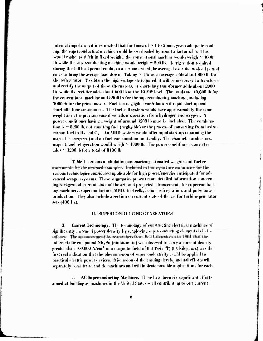
intrrnal impt'tiuiKT-, il is «-stimaU-d that tor times of ~ I to 2 min, jjivt'ii adniuat«' «-o«>l- in^, thr suptTcunduetiii«! inat-liinr could lit- overloaded Ity about a factor of 5. This would makr itsdl' felt in fixed weight; the eonveiiliaiial rnaehiiie would weigh ~ MHH) Ih while thr siifMrrondm tin«; rnaehirie woidd weigh ~ .KM) lb. Kefri^eration required during the lull-load p'riod could, to a certain extent, be averaged over the no-load period so as to bring the average load down. Taking ^ 4 W as an average adds about BOO lb for the refrigerator. To obtain the high-voltage de required, it will be necessary to transform and rectify the output of these alternators. A short-duty transformer adds about 2000 lb, while Hie rectifier adds about 600 Ih at the 10 MW level. The total» are 10,600 lb lor the conventional machine and B900 lb for the superconducting machine, including 5000 lb for the prime mover. Fuel is a negligible contribution if rapid start-up and short idle time are assumed. Tin« fuel-cell system would have approximately the same weight as in the previous case if we allow operation from hydrogen atid oxygen. A power conditioner having a weight of around 3200 lb must be included. The combina- tion is ~ 8200 lb, not counting fuel (negligible) or the process of converting from hydro- carbon fuel to ll2 and Oj. An Mill) system would offer rapid start-up (assuming the magnet is encrgi/ed) and no fuel consumption on standby. The channel, combustors, magnet, and refrigeration would weigh ~ 4900 lb. The power conditioner converter adds ~ 3200 lb for a total of 8100 lb.
Table I contains a tabulation summari/ing estimated weights and fuel re- quirements for the assumed examples. Included in this report arc summaries for the various technologies considered applicable for high power/energies anticipated for ad- vanced weapon systems. These summaries present more detailed information concern- ing background, current state of the art. and projected advancements for superconduct- ing machinery, superconductors, Mill), fuel cells, helium refrigeration, and pulse power production. They also include a section on current state-of-the-art for turbine generator sets (400 I Iz).
II. SUPKRCOMHCTING (JENKRATOKS
3. Current Technology. The technology of constructing electrical machines of significantly increased power density by employing superconducting elements is in its infancy. The announce men t by researchers from Mell Laboratories in 1961 that the intermetallic compound NbjSn (niobium-tin) was observed to carry a current density greater than 100,000 A/cm2 in a magnetic field of 8.8 Tesla T) (8»: kilogauss) was tin- first real indication that the phenomenon of superconductivity . <• dd be applied to practical electric power devices. Discussion of the ensuing devclo, mental efforts will separately consider ae and (h machines and will indicate possible applications for each.
a. AC Superconducting Machines. There have been six significant efforts aimed at building ae machines in the United States - all contributing to our current

Taltlr I. SyKtcm Wright and KIKI (^tnsiirnplion Summary
(ion linuous ()(N'ra(ioii
TurliiiK •-Oncralor
Mill) I'arariifUT Coiivriilioual Su| Mrroiulurtiii» Fuel Cells (lb) (lb) (II.) (II.)
(J«'n«'ralur 6,(H)() 2,000 4,500 5,(K)0
Kn^in«' r>,(M)() .r>,000 - -
I'owrr (loiidilioncr - - 10,000 10,000
Kcfri^rralion - ;{,250 400 -
Tolal 11 ,<KKI 10,250 14,900 15,000
Spt'cific Furl .5/l.pli ..Vhph 6/kWli .44/kWh Coiisuinpliun
Tolal Fuel lor 24«.V.(M)() 240,000 1.4(M),000 I05,6(K) 24 Hours
intc rmilt« lit ()[irra(ioii
(fcncrator ;{,(MM) 500 4,500 5,(K»0
Ku^iiu- .r),(MK) .->.ooo - -
Powcr (loniiitioiu-r 2MH) 2,6(K> 3,200 3.200
Kel'ri^tTation - »00 400 -
T«)lal 10,60« B/MKJ »,100 8,200
{•M-hnulogical base. Ail early effort was uiidertaken liy Dynateeli (Ä>r|.oration under
the spoiisorslii|i of the Aeropropiilsion Laboratory, WPAFH. In a series of contracts,
Dynateeli performed a feasiMlity study, speeifie problem area lift I), and the design,
construction, test, and evaluation of a 50-kW, laboratory-model superconducting gener-
ator. Overall emphasis was directed toward determining the feasibility of a JOOO-kV A
power supply for space applications. The lest machine specifications demanded a
24,000 rpm, 2-pole, 400-eycle machine having a rotating, superconducting livid coil
and a 3-phase supcreondiicting armature. Mechanical problems associated with high-
speed operation and resulting eleelrieal contact dilficullies proved loo severe for de-
finitive test results to be obtained on the machine. The machine was operated at 7500
rpm at extracted powers less than I kW. Total Air Force funding on this project over
the i%3-67 time frame covered by these contracts was $591 K.

Though the results of this effort wen* not all that was anticipated, the considerable heat-transfer analysis and the demonstration of the feasibility of operating a superconducting winding in a rotating, vacuum-insulated vessel were significant con- tiibuti'.nis from this program.
A second early effort was initiated at MERDC (ERDL) in l%:i with Avco Everett Research Laboratories as the prime contractor. This effort concentrated on electrical design analysis and resulted in the construction of an 8-kW test machine. The machine employed a stationary, central superconducting field (roil and an annular amLienl temperature armature; this configuration minimizes cryogenic cooling system problems. The 4-pole device had a 3-phase air core armature rotaiing at 12,000 rpm, delivering the 8 kW at 400 Hz via a set of slip rings and brushes. This was the first successful demonstration of a superconducting machine of significant power rating. Later (1969-70), an iron-core armature was designed, built, and tested; it delivered in excess of 16 kW from an identical armature envelop«*. The results of the effort verified the design equations for iron-free and iron-core machines, demonstrated that tlu elec- tromagnetic torques experienced by the field coil would not result in the loss of super- conducting properties as some early investigators feared, and lucidly demonstrated the thermal advantages (as well as electromagnetic improvement when magnetic saturation is avoided) of using a ferromagnetic stator core with teeth. Total Army funding on the contractual part of Ibis effort was .|80K.
Another Army sponsored effort was conducted by Avco for AAV LABS— Fort Lustis (AVCO-Eustis) in 1967-68. This resulted in a 2-pole. 12,000-rpm, 15-lq design-rated test rig having a rotating, superconducting field winding and a 3-phase arm- ature which could be cither superconducting or cryogenically cooled. The object of this effori was to provide a demonstration of the feasibility of a rotating, cryogenic field coil system and to determine experimentally the losses in superconducting windings due to alternating currents and to rotating magnetic fields. This test rig suffered a seized bearing in early testing and the resultant mechanical damage limited the rotor to speeds less than 3000 rpm. The primary results of this effort were the clear demonstration of high swept-field losses in unshie: led superconducting stator windings and a good tran- sient response analysis based on application and removal of a short circuit or of a resis- tive load. This test rig is now at MERDC where the rotor is being assessed for possible utilization in a demonstration device employing a conventional stator.
More recently, investigators at MIT have been pursuing the demonstration of the feasibility of superconducting alternators for power station applications under the auspices of the Ldison Electric Institute. Their first demonstration device was a vertical shaft, rotating field coil machine in which mechanical design of the rotor and a rotating liquid helium transfer coupling were the predominant features. The 2-pole, 3600-rpni,

>
3-phase machine was rated at 45 kVA on the basis of open-circuit voltage and short- circuit current tests.
A follow-up effort has resulted in the design and construction of a 2000 to 3000 kV A machine operating at 3600 rpm, 60 Hz. This machine is iron-free in the rotor and stator windings and employs either an aluminum eddy current shield (2000 kVA) or an iron shield (3000 kVA) to reduce stray magnetic fields outside the machine envelope. Construction is complete, but no tests have yet been reported on this device.
Westinghouse Electric (Corporation has two superconducting .Iternators under development - one under Westinghouse internal funding and one as an Air Force sponsored development. The Westinghouse-Air Force (WAP') machine is to be a 4-pole, 3 phase, 400-llz device producing 5000 volts line-to-line and rated at 1000 kVA continu- ous with a 10-second overrating of 5000 kV A. This machine has been designed, and a test rotor is in the construction phase. This rotor is subject to more severe require- ments than those of the commercial power frequency machines because of its 12,000 rpm rated speed.
The Westingliouse internal (WKC) machine program was intended to show the feasibility of developing superconducting generators for central station use and to identify technical problems not initially apparent in the design and operation of a substantially rated machine. The machine is a 2-pole, 3600-rpm, 3-phase device having a 5000 kV A rating and operating at 4160 V. The machine rating was verified experi- mentally by open-circuit voltage and short-circuit current tests but was not loaded to 5000 kV A. The only problem known to have existed was a vacuum leak in the rotating field coil dewar, and this has apparently been remedied.
A diagram of a typical alienator is shown in Fig. 4.
b. DC Superconducting Machines. There have been only two significant efforts in the development of dc machines in the U.S., both related to naval applications. General Kleclric built and tested an acyclic generator using a superconducting field as part of a theoretical and expierimental study of the performance of a liquid metal (Nak), current-collection system. This lest device u«'d a simple solenoid for the field coil; the MtjSn ribbon pancake-coil arrangement could produce up to a 5.7 T central Held at 500 A. Operating at 300« rpm und 2 T, this device delivered about 5 kW at 7000 A, 0.72 V; the generator was nominally rated al 20 kW, 2 V, 10,000 A, 4000 rpm. 4 T. The main contributions from the experimental effort were the demonstration of collector current densities to the range of 2000 A/in.2 and verification of the theore- tical predictions of the loss characteristics of liquid metal collectors in hiirh magnetic fields.
->-■'■--■ u

r
5 z
0 3
C
9 ■o
5. 3
10
J

r
The Navy's second effort is an in-house program at NSRDC-Annapolis to develop "shaped field" supcrcondueting motors and generators. This concept uses stationary superconducting field coils (solenoids) and an appropriate iron field shaping and shielding layout for either disk or drum type homopolar machines. Liquid metal current contacts are used. Design and test data have not been published, but an initial laboratory test machine is designed to be rated near 400 hp (300 kW) with anticipation of up to 1000 hp output.
Based upon the performance of the machines discussed, we can summa- rize the status of our current basic technology of superconducting machinery in the U.S. In the realm of ac machines, two configurations have been investigated, viz., the superconducting, stationary central field-rotating, ambient temperature, annular arma- ture (AVCO-MERDC) machine; and the superconducting, rotating central field-station- ary ambient temperature annular armature (AVCO-Eustis, MIT l&ll, WAF, WEC). The design equations have been verified for both configurations. Electrically, no problems exist which cannot be accommodated by proper design, including increases in the field current under transient conditions. Superconducting ac machines can be constructed to be either high-voltage or high-current devices; thus, they are applicable to either capacitive or inductive energy storage systems. With appropriate development, such rnuchines, including the cryogenic refrigeration system required, promise to be smaller
and lighter than conventional machines of equivalent ratings for high-power applica- tions (megawatts average power level).
Superconducting dc machines are inherently low-voltage, high-current machines. They are generally simplest from the cryogenic system standpoint but re- quire efficient current-collection means. These devices are best suited for high-current, inductive-energy storage systems.
4. Limitations of Existing Technology. It is clear from past and present pro- grams that superconducting electrical machinery can be built and operated satisfactorily. Since such devices operate at cryogenic temperatures, a compact, lightweight cryogenic refrigerator is n^uired for all but short-term (several hours) military missions. Develop- ment of such a refrigerator with u long life and high reliability has been a major part of MEKDC's cryogenic efforts. All machines investigate', in the D.S. to dale have relied on open-cycle cooling. Development of superconducting machinery will be best accom- plished by having not just a closed-cycle refrigerator system but an integrated refrigera- tor - refrigerator-load system: this lias not yet been attempted by anyone.
The high-current, slalioiiar)-field ac machines and the dc machines require efficient nirrcnl-ioilection means. The liquid metal collector systems arc the m«»st promising for greatly increasing ciirrenl-eolleclion densities but add system complica- tions und require additional auxiliun equipment. Losses associated with liquid metal
li

«•(»Hectors can IM- quite high. British ilevelupments un more eoiiventionul brusht-.s iiuii-
cate that .significant improvement» in solid brush, current-collection densities can be obtained as will be discussed later.
The rotating, superconducting field ac machines require careful mccbunical design of the rotor in order to provide adequate structural integrity while minimising
the heat leak to the lowest temperature regions and accommodating the differential contraction experienced as the rotor is cooled to liquid helium temperatures. A rolat ing shall seal for helium gas must als«» be incorporated in these design^. Such seals have
been designed and tested, and. satisfactoiy operation has been acliieved. These are pointed out as limitations simply because there is not a widespread experience in de- signing such components in the electrical equipment industry.
The larger ae machines under development are iron fr^H' in the armature wind- ing area, employing iron as a shield at a larger diameter. Such construction required the use of phenolics, fiberglass, and epoxies to support windings. This leads to higher eddy current losses in the windings, lower armature heat capacity, and lower heat-rejection capability. Until the armature loss and cooling requirements data become available for the larger machines, it will not be clear if such construction is really desirable. Tests at MERDC indicate that a more conventional toothed ferromagnetic lamination structure is preferable if magnetic saturation of the laminations can IM- avoided.
5. Pacing Problems. The primary problem retarding the development of stiper- conducting machines for high-power, landmobile applications is the lack of a compact, highly reliable cryogenic refrigeration system. Superconducting machinery is certain to be applicable to utility power sized fixed installations and ship propulsion type applica- tions (high-power, low-speed de motors; high-power, moderate-speed dc generators)
where higher ratings in a given frame size are achievable and ship design flexibility is significantly enhanced.
For some short-duration missions, it may be acceptable to provide cryogens
by tankage from a central or remote liquefier. In these cases, open-cycle cooling designs will be required, and such machines would be similar to laboratory test versions being studied. Generally, closed-cycle cooling is assumed to be preferred, and MERIKl's pri- mary emphasis in this regard has been toward development of the refrigeration system with the superconducting devices given a lower priority at this time.
The dc machines require additional development of current-collection means-
cither solid brushes or liquid metal contacts. Improving coll* '«»r current densities will
have a signficant impact on the general range of application of dc machinery.
12

6. Current MOD Programs. Then- an; lour fxi.stiiig l)()l) prx^rams which ruuhl impart on the (It-vt-lopnuuit of supcrcoiuluctin^ tnaitliint-.s as power suum-s lor pulscd- powtT suppiitvs. Th«' thrcc-phasc program U-ing (MTformed by Wfnlingliouw at l.ifna, Ohio, for tlu' Air Kurte is aimed at developing a supercondueting generator for airborne high-power applieation. The three-phase program is as follows: (I) analyses, prelimi- nary design, and critical component tests, including full-scale rotor tests, seal tests, and superconductor tests; (2) extended seal and rotor testing, detail design, machine fabri- cation, and checkout; ami (3) performance verification tests of I MVA continuous and lO-second pulses of 5 MVA with I minute between pulses. This cost-plus contract was initially estimated to have a cost of $564,000; reported KY 71 and 72 obligations total
$315,000.
The development program is a reasonable and necessary step; the objectives of each phase represent a logical grouping of efforts which must be successful to war- rant continuing to the next phase. The rei|uirenienls of emerging high-power weapon
systems will demand power sources with the capability achievable in machines of the type being developed. The optimum power source for the specific applications ami mission profiles for each of the Services may be quite different even though the basic technology is identical.
A second Air Force program is aimed at the development of lightweight Irans- formers for airborne, high-power supplies. Thermal Technology Laboratory of Uuffalo, New York, has contracted to establish design criteria and lecbiii(|ues for transformers having specific weights less than 0.4 lb per kV \ at power ratings of I lo 100 MVA.
Kleetrieal, magnetic, and thermal characlerislics are being modeled, and final design of a lo-l»e-specified transformer will be undertaken. Kstimated funding over KY72-74
is $70,400. The program is apparently aimed at providing high-power, step-up Irans- formers for high-voltage applications. Minimi/ing weight is desirable for airborne, land- mobile, and seafaring applications; and an analytical and experiineiilal program which considers electrical, magnetic, and thermal characteristics with emphasis on heat-rejec- tion capabilities is worthwhile. The results of lUv effort will likely be applicable lo high-power weapons technologv lor all Services in systems where an ac generator is the prime power source.
The Navy V in-hotise machine devclopmenl program being conducted al NSKDC-Annapolis would, if successful, provide a means lo design high-current, dc gen- erators for supplving current lo inductive energy storage devices. The shaped field con- cepl is as yet unproven, and the liquid metal, current-col led ion system requires further development. I'rogram costs were earlier estimated al $1.000,000 per year for 10 years. The primarv objeelive of the effort is to provide electric generators and motors for ship
propulsion (20 MW and up) which would yield enhanced .«hipboard design flexibility.
1.5

A fourth 1)01) spoiisurcd cffurt which «ould irn[ia(-t on the (icvelopinnit of «ic power sources for inductive energy storage devices is being performed l»y Westing- house for ARPA. The program calls for the development of a Wesliiii'liousr conceived segmentcd-magnct, homopolar torque converter (SMHTC); the largest part of the experi- mental effort will IM; aimed at the study of liquid metal, current-collection systems. A segmented-magnet, homopolar generator would have low-voltage, high-current capability; such a machine might be considered as a power source for inductive energy storage de- vices. In any case, further development of liquid metal current collectors should result from this effort.
7. Other Programs. Three utility power type efforts also could impact on (he development of ac superconducting machines for high-power applications. The details of the Westinghouse and MIT efforts have been described earlier. The Wesliiigliouse 5 MVA rated machine seems to have been deliberately overdesigned mechaiii-aily as insurance against first-time oversights which might cause difficulty, and the MIT 2-.'i MVA machine has not yet been tested. The machine conceived for utility power appli- cations may not be ideal for military applications, but the success of these programs will further establish the feasibility of developing superconducting machines as power sources for high-power applications.
A third development which is apparently iindcrwa\ is Iteing pursued li\ (icn- eral Klectric in Seheneetady, New York. Indications that a substantially rated (lu'sof MVA) machine probably of the ulilily power variety is under development can It*- in- ferred from recent publications, though no direct mention of such a program exists.
8. Foreign Technology. The most significant total effort in the development of superconducting machines for a variety of high-power applications has been undertaken by the International Research and Development Company, Ltd. (IRD), INewcastlc-upon- Tyne, England. Funding is primarily through the British Ministry of Defense-Navy (M()D-N)and the National Research and Development Corporation (NRDC), a "seed money" company for promising commercial endeavors. IRD has had a team of some 40 people working on the development of high-power superconducting machines since 1963. Their 50-horsepowcr Faraday-disc type motor completed in 1966 was the first operable motor of significant rating employing superconducting windings. Subscipient development led to the I« sign, construction, and test of a 3,250 horsepower (2.4 MW) motor designed to din i Irive a 200-rpm cooling-water-pump at the Fawley Power Station. The motor employs !he .segmented disc principle developed by IRD as a means to increase the voltage and reduce the current requirement of homopolar motors; solid brushes are employed. The segmented-disc principle allows operation at 430 V, 5,800 A as compared to a single solid disc device requiring 21.5 V and 116,000 A in the same si/c machine. Technological advances during the development time of this motor would allow the rating to be boosted to about 6 MW in the same machine size. IR I) is currently
14

building a supm-ondurtin« generator-mutur set designed for marine propulsion. Present
plans are for land tests only.
As an element in the development of high-power machines, IRD conducted extensive investigations of solid brushes. A metal-plated, carbon fibre brush construc-
tion resulted which promises to increase brush-current collection densities to the range of 300 to 600 A/in.2 as compared to 100 to 150 A/in.2 generally achievable for con- ventional brushes. This brush development will have significant impact on the design of high-power dc machines and could extend the range of applicability of rotating- armature ac machines.
Since the devices developed by IRD are equally useablc as generators and the
status of development is relatively complete by now, it is prudent to use this source for the supply of high-power dc machines where such sources are required. Output voltages up to a few thousand volts might be achievable. Such machines could be used to charge a capacitor bank where parallel-to-series switching or pulse transformation is employed to obtain the final output voltage or to power inductive-energy storage eoi's at high dc
curre.its.
This developmental program and other foreign efforts are reasonably well documented in the final technical report prepared by Westinghouse Electric Corporation
for the I .S. Navy-Office of Naval Research. The report on Contract #N000 l4-70-(; 0246 is entitled. "Survey of the State-of-the-Art of Superconducting Klectrical Machin-
ery": it includes summaries of all significant efforts and an international bibliography of papers and reports on the subject. Developmental activities were reported in England, France, (»ermany. Sweden, Japan, Switzerland, and Russia. As an example, a 100-kVA alternator has been built (and now tested) in Russia and a 1000 kV A machine with a
rotating, superconducting field winding is reportedly under construction.
9. Technology Forecast. The technology forecast for cryogenic refrigeration systems is included in the discussion of refrigeration developments. Solid brushes capa- ble (it 30(1 to 600 A/in.2 are under development in the U.K. (see Foreign Technology Section): at present the liritisli will not sell these brushes. The technology of liquid
metal contacts might be sufficiently developed in 3 to !> years to warrant their employ- ment in high-current machines. dc|)eiiding upon the progress of Navy and ARIVA pro- gram;«.
Kesulls of the MIT and Westinghouse MVA range ulternalor tests arc expectec!
to be available in the next I to 2 v'ars. The iron-free armature losses and cooling re- quirements determined in these programs might have a si^nificanl impact on optimum
designs for machines iti the I to 20 MVA range.
ir>

5000
3000
2000
1000 _
700
500
300
200 500 700 1000 2000 3000
RATED POWER - KW
(FOR 12,000 RPM, 400 HERTZ MACHINES)
Fig. ■'i. Kstimatfd weight vs. rated |M>W«T for inm-curi- suprrroniliK'tiiig altiTiiaUirs.
5000 7000 10000
16
i

I Insofar as the forecast for superconducting machines regards potential size
and weight vs. power ratings, estimates for a 1/MW-rated 12,000-rpm, 400-Hz alternator include 0.5-1 #^W for the alternator alone (Fig. 5), 0.8-2 #/kW for alternator with closed-cycle refrigerator, and 3-5 #/kW for a complete package including alternator, re- frigerator, gas turbine, and auxiliaries. Power density for the J iternator alone should be in the range of 20 W/cc or higher.
10. Priorities. The best approach to providing tlie high energy and high power required by weaponry under development will depend on the operational characteristics of the weapons and on land mobility/transportability requirements. Since these char- acteristics are not well defined at this stage of development, many possible alternatives to supplying the power required need to b'; considered at this time so that a more opti- mum combination of device and power supply can be selected at the appropriate point in the system development cycle.
Both ac and dc superconducting machines promise to be more compact and lighter than conventional machines at sufficiently high power ratings. The design and construction technology for dc machines has been sufficiently advanced by the British so that it is prudent to license from that source for systems where such a dc supply is the optimum. The dc machine technology for propulsion drives being developed by the U.S. Navy should be followed with an eye to the high-power weapons applications, but it is not essential to providing a good dc source for energy-storage systems.
For ac systems, it is preferable to develop the rotating-field-coil configuration for ultimate use at high power because this configuration is most amenable to being developed into machines having ratings of lO's of MVA in transportable sizes. With the advances in solid brush technology pioneered by 1RD, the limits of the extension of the power range of stationary central field superconducting machines need to be established. To do this it is desirable to design, construct, test, and evaluate the performance of a full-scale rau 'I machine (500 to 1000 kW) and base performance extrapolations and limitations on such data.
In considering the development of rotating, superconducting field coil ac machines, the primary problems to be faced are the rotating, vacuum insulated dewar and the rotating helium transfer coupling. The primary helium transfer seal configura- tion investigated to date relies on surface contact of a face seal; the fcrrofluidic rotating shaft seal seems to be much more reliable and should be invcstigaU'd for its range of applicability with varying ambient temperature.
The rotating, vacuum insulated 'cwar requires good mechanical and thermal design. A simple three-walled dewar with an intermediate temperature electrothermal shield and a sealed vacuum space is currently used. An interesting MIT design fo.- large
17

systems would employ a stationary outer wall with rotating vacuum seals: this configu- ration would allow the use of multilayer superinsulaiion to reduce radiative thermal losses and sealed or continuous pumping of the vacuum space and to eliminat;* windage losses by virtue of rotor operation in the high vacuum. Again, ferrofluidic shafl seals are good candidates for the rotating vacuum seals.
The weapons applications of the power supplies discussed will be somewhat similar for the three services, but the final installed configurations are likely to be quite different because of the variation in mobility/transportability and mechanical require- ments. Of the devices discussed, only the British dc machines can be considered to have essentially completed the exploratory development stage, and even these will need a detailed evaluation to determine their applicability to weapon systems power supplies as currently conceived.
Ml machines of both stationary and rotating field coil configi rations need to IK- further investigated, and a development which in some ways paralie's the current Air Force program, hut which is specifically geared to Army requirements, N worthwhile This would allow a redundancy in general development which is desirable in the event of difficulties in cither program and a sustained effort directed at an optimum power supply for Army weapons system applications.
III. CONVKNTION \L Tl KMINK GENKR \T()K SETS
11. Background. Turbine generator sets in the exact configuration suitable for Advanced Weapons Systems (AWS) have never been built. Turbine generator sets used by the Military have characteristics that generally arc suitable but have never been attempted in the large ratings anticipated for AWS; most have a capability of less than 100 kW. Turbine generator sets used by industry have generally l>een emergency power plants (in the order of 1500 k\\ or smaller) or "peaking power" units (in ratings to about 20.000 k\V ) used by electric utilit) companies as a means to handle peak power demands for relatively short periods of time (hours per day). Industrial turbine genera- tor sets will not be suitable for AWS because of excessive size and weight: the equip- ment is 60 Hz which results in large, massive generators: and the engines, while often derived from aircraft designs, have stressed low cost and long life resulting in versions of the engines in which both weight and bulk are inconsistent with AWS requirements.
12. Current Technology. The above discussion should not be taken to mean thai existing turbine generator set technology is hopelessly inadequate and does not warrant consideration for WVS. Relatively small, lightweight equipment is believed possible by extending aircraft practice to larger ratings and by accepting compromises in life. cost, and noise level of the equipment (as compared to industrial machinery). MKRIX! is currently involved in the design of an HR.VkW generator set which will weigh
IH

upproxiinatrlv 2900 lb—not imludin«» tiirl. Whilt* this power d'Misity is still not udt'quatr fur A WS, it is indicativr of progress being made. It is exprotrd tbul turbine geniTator sets will rmploy liijili-sjM'od (up t > 12,000 rpm) alternators at frequencies of 400 Hz or higher driven by engines running at higher speeds and higher turbine inlet temperatures than is acceptable fur industrial equipment. The larger ratings are anticipated tu be van ur trailer muunted while smaller sets could be skid muunted. In some cast's, several smaller engines wiiuld be "ganged" tu pruvide capability to power a generatur set uf intermediate capacity. "Ganging" uf engines is an attractive consideration since it cuuld allow declutching uf one ur mure engines tu conserve fuel during periuds uf luw puwer demand. Starting uf turbine generatur sets is relatively simple and quick. Even the larger sets can be started and loaded at full output within 2 minutes; in an emer- gency, this time could be reduced to as little as 45 secunds. Turbine generatur sets can be built tu accept a wide variety uf fuels, buth gaseous and liquid, with relatively guud efficiency (heat rates in the urder uf 12,500 litu/kWh).
Table 2 is a chart indicating weight and fuel comsumption for turbine gener- ator sets utilizing generaturs and engines which can be derived frum current technolugy based un comparatively long-life cunsideratiuns. By accepting cumpromises in life, noise, and cost, it should be possible tu du substantially better than the weights shown in the table.
Tablr 2. (ionvcntiuiiai Turbine (ientTators for AWS Anticipated Wrights
(ienerator Fuel KW W. ■ight (lb) Speed
(rpm) (Ions
(Cal/llr) Kngineg Pu&ibly Suitable
Rating (ieneratur Kngine Set Make and Model
1,000 «)20 1,000 3,r.oo 8.000 I4.,i i.yroming Model TF 258
2.000 l,4.M) 1.100 4,000 8,000 230 l.ycoming Model TF 40
5,000 2,600 3,300 7,300 8,000 .-ar. Lycoming Model TF 35A (Tliree)
10,000 5,000 7,r)00 .'0,000* 6,000 1070 CF. Model 3142
20,000 7,800 14,000 86,000* 6.000 I960 IVatt & Whitney Model Fl 4
* Includes wrighl uf van or traik-r.
IV. FUEL CELLS
13. Current Technology. Fuel cells are basically still in a development stage. They offer the advantage uf low-noise-level operation. Currently available stacks exhib- it puwer densities in the rang«' of 25 Ib/kW. Militarized systems (as uppused tu stacks) operating frum hydrocarbon fuels are in the range uf 100 to 200 Ib/kW. Development programs underway have goals uf 0.5 Ib/kW (excluding power conditioners) for mega- watt size devices using ll2, ()2.
19

Efficiencies of ~ 70% starting with Hj and O2 are achievable; counting pro- duction of Hj and O2, t\\" efficiency drops to ~ 40%. Militarized versions mentioned above are about 10% efficient. Reactant consumption is about 0.2 to 0.3 (kg/kWh). Although the fuel cell is not particularly sensitive to on-off switching of the output line, it nevertheless would cause an inefficiency in that the reactant flow would continue during the off time. Pulsed operation is not physically damaging, and fuel cells have been operated significantly above rated power in a pulsed mode.
14. Limitations. The position of technology, as demonstrated by H}, O] fuel cell employment in the space program, can be regarded as satisfactory for certain appli- cations both in regard to wo iking life and electrical characteristics. Improvements in the areas of electrode structure to increase limiting current density and in cathode cata- lysts to improve efficiency are needed.
Volumes and weights of slack elements are relatively low, but overall density is limited by auxiliary equipment. The output voltage of fuel celi batteries tends to be low due to the electrochemical reaction involved which limits, to a certain extent, high- voltage application.
15. Pacing Problems. For this application, development of high power densities is critical. Programs such as those of Pratt and Whitney, sponsored by Air Force, are defining constraints at present.
16. Technology Forecast. Fuel cells for fixed applications, e.g., consumer power, such as the 1254 kW modules being developed by Pratt and Whitney, should become available ii? the near future. Given adequate funding, programs underway will provide 'suits suitable for Army applications in the 5- to 10-year time frame. A high-power- density system (goal: 0.5 Ib/kW) capable of supplying megawatts for minutes is cur- rently ln'ing developed.
17. Current Programs. The Air Force (Wright-Patterson Air Force Base) (W PAFB) has a contract (S200k, FY73) with Pratt & Whitney for developing high- power-density fuel cells for airborne applications. The goal is to obtain megawatts for seconds to minute.« at a power density of 0.5 Ib/kW.
Vnm . Navy, and Air Force have supporting programs in areas such as elec- trode processes, catalyst recrystallization. advanced developments, improved matrix materials, and low-cost electrodes.
NASA's program is fairly broad covering basic research as well as fuel cells lor space cratl but is not directed toward high-power applications.
20

*r:\V;\ylft.f, JWttf^VlgW V *,cWB»;"i*Q'** ^- P*V»y ^. '■<fcilW«WffVi IflntrviatVKrl, ftf -«a- w
18. IViorities. The Air Force-Pratt and Whitney effort should be followed. Modules should he obtained and tested if warranted.
V. Mill)
19. Current Technology. The generation of electricity by MUD generally falls into three classes:
a. Open-cycle plasma generators.
(i) Combustion generators.
(2) Detonation or explosive generators.
b. Closed-cycle plasma generators.
c. Closed-cycle, liquid-metal generators.
Plasma and liquid metal Mill) generators are often confused with each other because of the coincidence that llic alkali metals such as potassium, cesium, and IKbiiim are used as the working fluid in the liquid metal Mill) systems: and these same alkali metals are also used as seed materials to enhance the conductivity of the plasma in (lie plasma MHI) systems.
At the 5th Internalional Conference on MUD Klcclrical Power. April l{)7l. Munich, it was concluded that all three classes of Mill) generalurs arc lecliiiicall\ proven concepts and promise the generation of highly efficient electrical power. Mill) power generation possesses the following attractive features: relative simplicih . high power to weight and volume ratios, favorable scaling chancleristies. continuous and pulsed power, and inslantaneoush available power. In a rapid!} growing electrical market, (lie in- creased [>ower output for given fuel costs, air pollution, and (licrmal pollution could be important factors in favor of MUD power generation. Mthou^h MUD power generation has been lechnicalh provni. it ha> iml be<ii demonstrated llial MUD power gerieralion can eon pete economicallv with comcnlioiuil. central |n«wer «icneraliorr.
Open-cycle combustion MUD s\stem>liavc now readied the prololvrie stage. Several countries, particularlv the 1 SS|{. have programs in open-cycle MUD and arc developing systems capable of overall efficiencies between Wr and Wr. Ilv conipari son. central commercial power plants have overall efficiencies between U)'r and 4',Vr. Kconomic studies (MI larce-scale. open-cycle MUD power slalions for continuous opera (ion on has«- load indicate that these systems in conjunction with conventional generat- ing systems could be made economically attractive, even considering the requirements

for minimizing air pollution due to sulfur oxides. However, the economic usefulness of open-cycle MUD systems, whether for base- or peak-load operation, must differ from country to country due to the large variation in costs of fossil fuels and the nuclear generation of power.
In the field of open-cycle explosive MHD, the Soviets recently succeeded in obtaining useful pover from explosion of hydrocarhon fuels and oxygen. Explosive MHD appears promising for the direct generation of pulsed dc.
Small, closed-cycle plasma MHD experimental generators in a number of countries have been operated successfully. The results of these experiments indicate that is is possible to predict the performance and characteristics of multi-tncgawatt generators. As of April 1971, the West German facility "ARGAS 2" is the only MHD device to employ a superconducting magnet.
Experimental liquid metal MHD generators in the I kW ran^c have been demonstrated in a ruimhcr of countries including the United States. The goal of liquid metal Mill) is the development of very reliable generators which would he suitable for space applications and submarine propulsion systems. Liquid metal MHD does not appear practical for commercial power applications because of its limited output.
In general, military technology of MHD is not related to commercial power plant technology. Only in the field of peaking power plants do the technologies over- lap. For emergency sources of central power, peaking power plants will be required to provide megawatts of power "almost instantaneously" and to operate at these power levels for short periods of time. These requirements are similar to military require- ments for high-power-density power supplies with short duty cycles and can be supplied by open-cycle plasma MHD. Explosive MHD appears to be attractive for pulsed-power applications because of the direct application of pulsed dc power.
Supercomluctinf; magnet technology has advanced to the point where super- conducting magnets of various designs can be incorporated into MHD systi ms.
20. Limitations. Plasma MHD generators arc restricted to the generation of dc power due to the comparatively low electrical conductivity of the plasmas. Typically, the conductivity is between 10 mho/meter to 100 mho/meter. This low electrical con- ductivity results in low voltage generation, and, consequently, ac power cannot be efficiently produced because the magnetic field cannot be efficiently varied to induce ac voltages. On the other hand, the electrical conductivity of liquid metals is about 106
mho/meter which is only about 100 times smaller than the conductivity of copper at room temperature. Liquid metal Mill) generators offer the capability of generating either dc or ac power, with a wide range of frequencies, at selected voltages.

All important liinitaliun of existing open-fyde «■ombustion Mill) pmrrators is thrir expenditure of fuels which are not readily available in the Army V lo^istieal
system. Ordinarily, these devices an' fueled with a liquid fuel (typically a hydrocarbon), an oxidi/er (usually gaseous oxygen), and a seed compound (potassium or cesium carbonate). Present-day combustion Mill) generators have to us«- oxygen or nitrogen- oxygen mixtures as the oxidixer no matter what fuel is employed. Future Mill) devices
may be able to use air as an oxidixer, and the logistic problem of supplying tanked oxygen will be eliminated. Fuels wllich yield plasmas with significantly higher electrical conductivities than JP4 are not presently available in the Army's logistical system. \n
example of such a "high conductivity" fuel is cyanogen (^2^2)- The logistical problem of supplying seed material can be minimised with the development of an effective seed recovery device.
The lifetimes of the major components of plasma Mill) generators such as channel, no//Je, and burner will be limited due to the erosion effects of high-lemperatiire and high-velocity plasmas flowing lliroiigh these components. Lifetimes of these com-
ponents are further shortened due to erosion and spalling caused by thermal shocks llial occur < ach time the generator is run.
The efficiency of explosive Mill) generators is presently limited to 1.5'/. The inefficicnev of the conversion of explosive chemical energv to electrical energy means that relatively large amounts of explosives per pulse will have lo be detonated to achieve usable power levels for pulsed operations. In addition, (he coniainmenl of the
comparatively large explosions per pulse will cause (he generator itself lo become bulkv.
The lifetime of explosive MUD generators will be scverelv limited by the erosion caused by the passage of the explosive products through the channel.
21. Limitations of Kxisting Devices. The eurrenl upjier limits of operation for
Mill) systems are:
a. Continuous combustion Mill) for low-diitv cvcle.«.;
Power
Specific I'ucl (lonsumplion
Specific Wcigbl {\i» fuel and oxidizer)
10 M\\
1 kg/sec r.«)!' Il./hr
MW k\\
<»._' k-: o.r. ii. MW k\\
Oulpiil Vollagf ;{()k\
_'.{

b. Pulsed fxpkisive MUD:
Power 10 MW
Pulsed KIKTJIV 50 kj Puls«- [himtiun 100 ß sin-
Pulse Ratt- < lOpulses/s.»
Rffkieiu-y I .~yfA (".urrviil Rise Time 10 ^ see Output Voltage lOsolkV
22. Pacing Problems.
a. A siimmur\ of critirul (eeluiieal |in»blems lor ojien-eyele eombustioii Mill) is as follows.
(1) (iliuiitu-l und electrode erosion due to liij:li teni|M-rat(ire and lii<;li
\eloeity plasma.
(2) Insulation breakdown.
(3) Keeovery of alkali seed material.
(4) Current distribution in tbe plasma.
(5) Reduetion of component size and wei«;lit.
b. A summary of critical leebnical problems for pulsed explosive Mill) is as follows:
(1) Improved conversion of explosive cbemical energy to electrical energy (higher efficiency).
(2) Multi-sbot capability.
(3) Reduction of component si/.e and weight.
e. A summary of critical problems for liquid metal MUD is as follows:
(1) Flow channel erosion dm- to velocity of liquid metal.
24

(2) Kiiliictioii ul' rrirlion Ins.srs in Ihr ^cnrralor aixl lit|iii(i nit'lal HKM
c-onipoiM^ils.
riK-lal. (3) Thermal and rlfrtrical insulation «>f Ihr gcnrrator from tin' liijuitl
(4) Control of slip losses ami shork losses in the two-phase flow.
(.">) (iorrosioii and liandlin<; probbm» of liquid metals.
23. Current DOD IVc^rams.
a. Overall DOD Effort. Current DOD MM!) efforts an- listed in Tables 3 and 4.
lublt .1 Ciirnul \a\\ Mill) KllorU
I'll \... •\'.'»'ii(\ (iontracttir (kiin(»li'tK>ti Dal.-
Funds (K*)* y\ -7:1 FV-7i
Titl.-
.-)6J ONK CK COM IW.«> MIIDC.nStudv 2W»y ONR (;K CONT ^..»(AKI'A) Mill) l**it 2670 (»NK Arfjmri«' \al l.ali COM' .■jr.o.o THo-nia.srMIIDCin
2r.H7 ONK Vrfionn«' Nal l-uh CONT 13(1.0 Liquid Mrtal MUD 2020 ONK (iolorado Stale V. COM' :{2.w Mill) Plasma
Invi'stii.'atioii
2174 (»\K Xrpmni' Nat l^ili COM (KV.r2:3n.0) K.valiialioii of Liquid Mrtal Mill) lor
P<)W»T Cfll
•These fiuures are bd.sed II|MIII data taken I'ruin the latest PIC sheets available in the Kleetrical Kquipment files (Jan 1974). In.sume oiir». th« V\t. sheets have not been kept up to «late. Suppleinental AKI'A ftiiHlsare shown where tliew figures were available.
b. Air Force. Tin Air Force Aero Propulsion Laboratory (AFAPL) has an
extensive MUD pio^ram (over 9(K) k dollars in FV73) aimed at developing hi^h-power pulsed and eontinuous Mill) generators suitable for airborne applieations. The> have
»wo pulsed explosive MUD contracts (Avrn ami llereules) whose common objective is to demonstrate operation of a 50 kj/pttlse, 100 /xsec pulse width, and at least 10 pulses/ sec explosive device. Avco's explosive MUD ueneralor will use a liquid explosive and Hercules will use a solid explosive. Hercules has already obtained a single pulse of 25 kj using a seeded mixture of a military explosive (C-4) and cesium. In the field of con- tinuous combustion Mill), the AFAPI/s hi<;h-power density combustion generator effort at AVCO has l»ccn successfully completed. A specific power otitpul of 0.5 MW7 (kg/sec) (400 kW output at 0.8 kg/sec total mass flow) was obtained usiii" a seeded conventional hydrocarbon (tolueiie)-oxy<;en fuel. In Mill) magnet technulogv, AFAPL
25

.a v. b r »f -r r ^3 n C ,
-
H
5 £
2 c X
JS
it 3
r,
■
c
"S
s J
'*- J2
X 1 7
i. u
■2 2 #
"1
7
u o
T. b.
u
C \
Urn >.
-a cc tL<M _2
' z *■ •w* __, b. 5 c *w T ^ r —■ #r X M
i —
> # it .3
9
"5 e 2
f—
.< ■7 =
U.
£ a 1 is
C
= .^ = c- 5; U> C " u fl *^ ^ X X 0
<■ 60 "P 3 m =
^ r^
u 5L TL
P i ^ ** J i. a. JÄ
£
'1-1
* i
■•/.' u ^i ' - f. ' **
^* r i r 1 -
I* I* ^C I- L- •^ ^^ s^ ^* !zl
o cc 8 s S I- 3 c? W Q Ov — — O M ^f
" c
^ s s s s s s I"
S x
_ 3
J 7
!a !
i i
J2 -
* —■ a-
/. T "7
■/, n
r 7 —
/. **;
1 >l ±
/. /. A /. I.
X /. /. /. '/.
- ill
"M ^ i- t i~ 2 ~ ~ U i2 TI "M -M Cl Ci
2
1.5 ?■
g if J
26
has a program to develop and test a lightweight (1000 lb). 4 Tsupereomiueting magnet. Supereondurting magnets were built at the Magnetie Corporation of Ameriea (MCA) and Ferranti-Paekard, l-ld. The MCA magnet produced a peak field of 3.8 T, but the problem of excessive conductor m'vement has not yet been eliminated. Currently, APAFL has a contract with MC ' to test the Ferranti-Paekard magnet.
Finally, the Air Force has a spectrum of research contracts in Mill) with universities and research companies. These efforts are funded primarily by AFAPL and AF Office of Scientific Research.
c. Navy. The Office of Naval Research (ONR) has a program in liquid metal Mill) for power generation. Currently, ONR is funding an effort at Argonne National Laboratory to design and construct a two-phase Mill) generator; ONR is also funding a study on the possible Naval applications of liquid metal Mill) at Argonne, a liquid metal generator study, and an experimental study to determine the feasibility of an MHI) laser at OF.
d. Army. The Army has a small surveillance program in Mill).
24. Foreign Technology. The USSR has the largest MUD research program in the world. The Soviets have major efforts in three areas: open-cycle and closed-cycle plasma Mill), and liquid metal MHD. The largest effort has been in ojien-cycle Mill) and has led to the construction (1971) in Moscow of a pilot MUD plant (11-25) with a power rating of 25 MW. The l'-25 is being slowly brought up to full power. Valuable data on the service life of the basic components of Mill) plants is being obtained. A significant effort in liquid metal Mill) is the construction of a model plant with a thermal input of 300 KW.
The Japanese have the second largest Mill) program in the world, and their major goal is the building of a complete model of an open-evcle power plant. A pre- vious effort has resulted in an open-cycle generator (KTL-Mark-ll) which has produced a mega-watt. Presently, a generator (FTL Mark-V) with a supereonductiiig magnet and a model power plant (FTL Mark-VI) have been constructed and preliminary tests are underway. The Japanese have excellent capabilities in applied supercomluclivilv — especially in materials and magnets, and they can be expected to employ supercunduct- ing magnets with their Mill) generators.
The Federal Republic of Cermany had an extensive program in Mill) but has recently terminated these efforts for economic reasons. The FRO (government felt that it would be cheaper to buy the technology rather than pay for the develop- ment. Some of the Mill) workers are now working on controlled fusion; the rest have been scattered throughout West Germany. TU Italians are also phasing out their
t'xcdh'iit, bul small, «'fforl in «■lowd-ryrlc Mill) in favor «»(" fusion n-scanli. Th»' Frrnrli
effort in liquid metal Mill) isslowlx iH-in^shiit down. Th*' only Wt-sl Kunipeansto
liavra viabli" larp- Mill) «-fforl at prrsml aro thr Dutch. Th«'v have n-tentlv put an
open-cycle plasma installation rated at 5 MW thermal input into operation. Other
Kuropean countries with small research efforts iti Mill) arc Austria. (i/.cchoslovakia,
Poland, Sweden, and Switzerland.
The Canadians arc doing research in non-equilibrium Mill) and arc building
a iar^e thermal blow-down ex|Kfiin«'iit having a thermal input of 10 MW. They are
also planning the development of a small, open-cycle facility (2 MW electric). InitialK .
this facility will have a conventionu! magnet. Future plans call for replacing the con-
ventional magnet with a superconducting magnet. The Australians also have a small
research Mill) effort at the liiivcrsilv of Sidney.
25. Priorities. Two classes of Mill) generators are attractive candidates for
specific militarv bigh-power-supplv requirements. The military's requirement for a
lighlweighl. imilti-megawalt generator with short duly cycles can be satisfied b\ an
open-cycle combustion Mill) generator with a su|>ercoiiducting channel magnet. Such
a generator could us«- a seeded conventional hydrocarbon fuel and gaseous oxygen as
the oxidi/cr. The Air Force has previous!) demonstrated a prototv|H- of this variety
with n conventional channel magncl. This combustion generator bad an outpul of
400 k\\ and an attractive specific power output of ().."> MW/(kg/sec).
The military's requircmcnl lor a pulsed power supply capable of supply in<:
miiili-kj pulses could be filled in the future by an explosive Mill) generator with a
Mipenoiiducting channel magnet. The \ir Force has successfully demonstrated an
explosive Mill) generator. \ solid explosive {{',■ I) generator (Hercules) has produced
a 2~>-k.| pulse to dale. Multi-shot eapubililies are currently being investigated bv
Hercules.
The extensive Air Force programs in Mill) should be eloselv monitored.
The results of their investigations eoiilfl lead to Mill) generators suitable for \rm\ re
ipiircments lor high-power, pulsed anil mnlitiuoiis power supplie».
vi. pi I,SI:IH)\\I:K
26. (lurrrnt Teehnologv. Some weaiion system;, under current eonsideralion
require bigh-energv pulses of electrical etnrgv. For this Ivpe of application, rotating
machines are generally not sttislaetory. In inanx ca>e>. it is not practical to M/C a
inaehinc lor the peak power required or to dcM>Mi f«»r overload. In any event, it is «lit
Hi nil to suppb pulse* <d I05.| or gr«'at«'r having wiilths «d'< I nis<-c direi ll\ from the
machine. However. Mill) gen«Tat«»rs offer lhi> capabilitv. (See Se« lion V .) In MH b
JH

r instamrs, puls«' pruduction may b«' obtained tbrough (iischargf of circuit elements. Both capacitors and inductors can be used as the energy storage element in these circuits and each offers special characteristics.
At lower energy level (<105J) and for fixed installations where size (or weight) is not of primary importance, capacitors are presently the best choice. Present capacitor devices offer energy densities of about 500 kj/m3 or 275 J/kg for the storage element alone at the 5 kV level. In terms of specific weight, i.e., weight per unit
3kg energy stored, 275 j/kg is about 3.6 x 10 —- . Capacitors offer the advantage of rel-
atively easy switching using previously developed techniques. Low jitter spark gap switching is presently available for fairly low repetition rates. For higher repetition rates, the clearing time of the spark gap switch limits the application to ~ 10 pps. Ignitrons permit higher repetition rates ("" 400 \h) but are relatively expensive (~ $10K not counting control circuits) and bulky.
Although the specific weight of capacitors is dependent upon voltage level, it is not a function of energy level. This can be seen by noting that the plate separation is determined by breakdown strength; thus both the energy stored and the weight are proportional to plate area and, therefore, specific weight is constant to a first approxi- mation. For inductors, however, the weight is approximately proprotional to the number of turns as is the field strength. Since the stored enepgy is proportional to the square of the field, the specific weight is inversely proprotional to the number of turns. Therefore, the spe-ific weight is inversely proportional to the square root of the energy. This reasoning is borne out by the energy-weight relationships for existing systems: typical values are ~ 2 to 3 x I02 kg/MJ (coil and structure) at the 1 MJ level, decreas- ing with increasing energy.
The favorable specific weights for inductors indicated above are promising: however, utilisation ut present is limited for several reasons. The use of inductors to supply pulses of power at high energy levels requires opening a high-current switch in an inductive circuit. INo suitable solid-stale switches are presently available. Mi^h voltage/high current mechanical switches have Ixrn used as interrupters but are de- signed for use in ac lines where a "natural" current-zero will occur within V-» cycle. To use similar switches for the de application entails the addition of a counter pulse circuit to force a current-zero in order to avoid high losses in the switch. Such circuits re*|uirc capacitivc storage of a percentage of the total system energy : this depends on system energy level but is estimated al ~ \iV.f for the mcgajoule level. Some schemes would allow recovery of this energy in the load.
Mechanical stress will be a significant consideration in any high-cnergv sys- tem in the range of interest. In this resjiecl. both capacitivc and inductive storage
2*)

share similar problems. The hi<jh «■irrlroma^ru-lk; fk'Ms assuriated with tlu'sc «■lemrnl.»
anil with the Iraiismissiun of large eurrenlsat high voltages exert large I'orees on the
leads and support strueture as well as on the elements themselves. It is also possible
for nun-negligible I'orees to be exerted on surrounding materials. An estimate lor a
partieular solenoid storing ~ I05 J indicates (under statie eonditions) stresses on (he
order of the yield strength of eop|N*r (a major eonstituent of some eonduetors). The
problems of winding novement and similar effeeLs can Iw minimi/.ed at the expens«-
of system weight by earefid design.
Supereondueting induetors have generally Iwen maintained below the snper-
eondueting transition temperature by immersion in a hath of helium licpiid. Sut li a
technique is convenient for some purposes, but integrated refrigeration is more de-
sirable from an efficiency standpoint as well as from a consideration of the difficulties
inherent in making a two-phase system a .self-contained unit while retaining mobility.
Oryogenie refrigerators are available, but some development is neeessary to make them
sufficiently mobile and reliable for field use. (See Section VIII.)
Great progress has been made in materials development in the decade since
the first high-field superconductors were discovered. Materials are now available which
remain superconducting during charge or discharge rates of 5 to 10 T/see. Such ma-
terial appears to be marginal, at liest, for pulse rates of .l/see, assuming deep discharge.
Improvements in materials with the goal of practical application are required. (See
Section II.)
Voltages of the order of JO's to l(M)"s of kV will be develo|M'il across the
storage element during discharge. Insulation capable of withstanding this voltage at
low temperature is required.
The external field of an inductor iti a solenoid configuration is quite high:
this presents a problem in shielding neighboring equipment. bAcn if no eleetrunic
equipment is located nearby, the surrounding metal structures can be subjected to
significant forces bv the magnetic field. A sbield would therefore be required for many
applications. Active shielding seems to be a possible method of accomplishing this.
\n inherently low external field can be achieved with a toroidal configuration; this
would eonsiderab'v reduce the shield required. For comenienee of construction, a
torus can be approximated as closely as desired by pancake or short, cylindrical seg-
ments. Other eoaligurations with low field at a distance are also possible.
The preceding discussion has been devoted principally to high-energy pulses.
For systems requiring lower energy pulses at the same average throughput of power,
different techniques may be used. Pulsed MUD, for example, appears attractive for
pulse energies in the lü's of kj and repetition rates in the l()2 Hz range (sec Section V).
M)

Murr convrntiutial IrcliiiiqiD-s arc liascd on Ihr use nl'a |)nlsr r**rtiiiii<: tulwurk (PKN)
led l)\ a v*illa<;r or a oirrcnl soiinr. Sonif lorni ofctuT^x buffer, fur examulr. an in-
(iiiclor or a llvwIifrl-ircrMTatttr rornliinalion, ma\ IM- used |o i-as*- llu- dt-mand on (IK
sourer olprimt' inovcr. Flywlircl tcrlinido^v. in |uirliruliir, lias hrrn invi.sli^atcd fur
transpurlation syslcins. (lonsidtTation has IMTII «livcn l<» the use of (hi' li<'ld windings
of fiftu-ralurs (Mill), csiirciallv) asan indiirlivc purliun uf llic PKN.
27. Liniilations. t'rincipal liniilaliuns of cxiMtinu; capacitor hanks and normal
machincrv arc related to size and wei<;lil. In addition, tin numher of components
ret|uircd may IM- lar^e, adding to the complexity and reducing the reliahility of the
system, (iapaciturs theiiis«'lves are limited hy achieved energy density. Systems iisin«;
capacitors morcuver require «"ither the production of high voltages for charging or a
larijc numher of switch elements. It ap|)ears, however, that an inductive system can
IM- made in a reasunahlc size-weight configuration for the application and that the
numher uf circuit cumponenls could he reduced as compared to an equivalent capa-
citor system. The limitations to such an inductive system are in the switchgear and in
cuuiing the energy-storage device. High voltage/high current switching is being de-
veloped as is refrigeration, hut inipruveinents in reliahility and capacity arc essential.
Fur siipcrcunducting inductors, material properties impose special limitations; fur
example, the maxinuun dlt/dl which can he tolerated.
28. Facing Problems. The dcvclupmcnt uf reliable refrigeration fur use in the
field will IN- a controlling factor in the dcvclupmcnt uf systems utilizing supcrcunducl-
inj; or cryogenic devices. Capacitor development tu increase energy density will control
capacitor-based systems. Kefinement of switching systems will be necessary in either
case, hut fur low-repetition rales solutions appear to he available.
29. Cuirenl Programs. Air Force (Aero Propulsion bah, Wrigbt-Pattcrsun Air
Force Has«') (WPAFH) has several programs underway at this time relating to inductive-
energy storage. In FY's 71 and 72, cuntracts with AVCO and Magnetic Corpuration
of Amerif a (MCA) fur inductive-eticrgy storage investigations totalled $^89.2K. This
led to the FV73 eojitract with MCA for SI 77k to build the 100 k.|, .i pps coil. Addi-
tional contrails with Wcstinglu.use ($IS4K. FY7a). MCA ($26K. FY73). Hughes
($I45K, FY73). and Purdue ($I7K, FY73) treat the switching problem .separately.
NASA-bcwis has programs in capacitor improvement, nutably fur high-
encrgy-density. thin-film capacitors and polycarbonate capacitors. Army (MKKIH')
has shown that some improvements in V A rating arc possible using heal pipe cooling.
In industry, bawicss at Corning Class has shown high-energy-density storage to be
possible at 77 K using Corning tilanale-glass-ceramic materials. In addition, increased
energy density appears possible through development of carbon capacitors.
31

Tli«- Frnu h IIUM- iin arlivt' pro^rarii lor iiivrsli^uliii^ supcrciindiiftiitg, iiuiiittiv«-fiuT^v storagi' und ha\f mad«' MHIII- (tn ifrcss as fvidi'iK-cd 1»\ puhlita(i«iiis in Ihv upni liti'ralur«-.
Publications by Sovit't Idiu- »cinitt Is indicate <-«)nsid«Tabl«' interest in induc- tiv«' storage and pulst- production. Tlw extent of tlic program is not known.
VII. SUPKRCONULCTINC MATERIALS
30. Current Technology. (lurrcntly, there are several alloys use«i to mak«- com- mercial superconduct«>rs. Tin' most fommon are niobium titanium (M»Ti) and niobi- um tin (M»3Sn) which are integrated in a matrix of a g«>od normal conduetor, usually «opfMT. An eidargt-ment «)f tli«' «^«»ss section of a typical cniduelor is shown in Fig. 6. This matrix is essential to [woduee a stable, enrreul-earrying wire. Kaeh superconductor has intrinsic limitations in magneti«- field and in temperature. The magnetic field limi- tation is called the critical iVId. If a siip«-rc«ind(ic(or is subject to a magnetic field greater than its«'ritical field, it will be<-ome a normal coiiduclor. The temperature limitation is called the crili« al temperaliire. an«l above this tem|K'rature a supereon- duetor reverts to its normal comlueting slate.
Niobium titanium, which has a critical temperature of !0oK md a «ritical field of 12 T (120 kilogauss). has the a«lvantagc of bi'ing very ductile so that fabrica- tion is easier and the sup«-rcon<luctor eheafier. Keducing the sixe id' the ciirrenl-carry- ing, su(ier«-onducting filament r«-diiees hysteresis losses and thus leads to more stable charaeteristüs under transient field e«inditions. liecause of its high ductility , NbTi can IM- easily nianufaclurcd in multifilament «'ondmlors. These are wires with many small su|M-r«-«)nducting filaments imb«-d«i<-d in a matrix of copper. The NbTi filaments have diameters ly pically in the rang«- of I t«i M) miertMis, and over I (MM) filaments can IM*
incorporated in one wire appmximately 0.01 "i inch in diameter. In the most recent materials, these filaments an- twisted inside the matrix so that ihev spiral along the length of the conductor with a twist pit« It of I to 10 per inch.
Twisting is especially imporlanl in applieations involving lar^c transient mag- netie fields lM-cause it eliminates iiidu«-<-d cntss currents flowing in tiie matrix between filaments. A matrix of relatively high resistivity eopper-niek«*! alloy (iiiproiiiekel) is s«tmetimes used to impede tliesi« cross currents. Typical matrix to siiperconJuetor ratios are between i t«> I and 2 to I. Tlu- major disatlvanlage of NbTi ■« thai it has -i much lower «ritical field than M^Sn whi«:h must be used in high field -pplications.
Ni«)biurn tin which has a «'ritical terapersture of I80K and a «Titieal Vield of 2.'> T is used in applications WIMTC fields «»f 7 T «»r more are required. Ilowev« r, NbjSn isextremclv brittle and cannot IN- drawn inl«> win- form. Currently, M^Si is available
.{2

\ ij. >i I nl.n.'i iihril nl (In . r '' li"!! "I .1 l\ (Hi .il i iiMiliiclur
M

only in rectangular cross section tape or ribbon. This ribbon consists of a deposit of Nb3Sn a few microns thick laid on a metallic substrate with a normal stabilizer as the outside layer. This construction allows the composite to be bent without damaging the superconductor. Coils made fron iNb3Sn tape are usually of the pancake variety. A pancake is simply a length of tape wound on a spool just as a roll of scotch tape. Many of these pancakes are stacked on top of one another and connected in series to make a solenoid. Solenoids made from NbaSn tapes have good high-field performance; but, not having the advantages of small filamentary twisted conductors, their transient- field behavior is generally not as good as that of M/Ti.
A vanadium - gallium alloy, VjGa, is the most recent commercially avail- able superconductor and has even better high-field performance than Nb3Sn. It is also very brittle and thus available only in ribbon form. Since it is relatively new on the market, V3Ga has not been used in many applications.
Recently (1973) a new record high critical temperature of 23.20K was re- ported for an alloy of niobium and germanium (Nb3Ge). Even though it is not pres- ently known that this material will be commercially practical, its discovery represents a significant advancement since its critical temperature is almost 3 degrees above the boiling point of hydrogen. This means that future applications of Nb3Ge could utilize liquid hydrogen as a coolant rather than liquid helium. !Nb3Ge also has outstanding high magnetic field characteristics.
31. Limitations of Existing Technology. Present superconducting materials are severely limited by their operational temperature which is less than 90K for NbTi and 180K1W Nb3Sn.'
There an1 several other limitations for practical superconductors. Niobium- titanium filaments can presently be no smaller than a few microns, und there is a coupling limitation on the mimlxT of filaments in a composite. Twist rates cannot ex- ceed 10 twists/inch due to material strength. In practical applications, NbTi is also limited to magnetic fields below approximately 7 T. Above this field, superconducting NbTi has a low current density.
Due to brittleness, Nb3Sn and V3Ga cannot at this time be commercially produced in the form of wires. This is a very severe limitation for if these alloys could be manufactured in wire form they would offer the advantage of a high-field, high- current density conductor with the transient-field advantages of twisted, multifilament conductors. The higher operating temperature of i\n3Sii greatly reduces the problem of removing the heal generated in coils.
34

32. Technical Forecast. Several American companies have current research pro- grams aimed at a flexible wire conductor of Nb3Sn, and development is possible in the next few years.
There is considerable effort in the development of higher temperature super- conductors. This work b performed in many countries, in universities, industry, and government. There are no indications of major brc ^Ktliroughs in the foreseeable future.
New conductors with smaller and thus more superconducting filaments of NbTi have appeared on the market the last few years and this trend is likely to continue.
A Japanese Company has recently marketed V^Ca in ribbon form. This material is useful in coils which generate over 10 T and its use is likely to increase in the future, especially if multifilament wires can be commercially produced at a com- petitive price. Small lengths of multifilament V^Ga have been produced in the labora- tory by a new solid-state diffusion process.
There is some interest in the development of high-fieid superconductors of alloys in porous glass. Although some success has been experience«!, it is very question- able that these materials will IM- able (o compete with the more established supercon- ductors in the near future.
Other materials with potential future use in superconducting coils are Nbj (Al.osf't'-os) an(J NbAlj, both brittle compounds, and the proprietary alloy of MbTi-llf which can be easily drawn into wire form.
33. Current Programs. While there are rnaiiv IH)1) sponsored programs in the field of superconductivity, there is currently very little effort directed toward the development or improvement of superconducting materials.
The following American Companies are engaged in research, development, and production of high-field superconductors:
Norton Co., Supercon Division: IWfi single- and multi-filaincnl copper stabilized conductors. Up to 400 filaments/.•onduclor. Filament diameter .0005 in, twisted or untwisted.
Magnetic Corporation of Arne.ica: NbTi alloy emhedded in high-eondue- (ivity copper. Single and miiltiiilament conductors up lo 360 lilaments/conductor, twisted 1-5/ineh or untwisted. The» also have a research program in multifilament M13S11 composite conductors.
35

Ititt'rmagtiftits Gciu'ral dorp: ^b3Sll ta|M' for liivli-magiiftic-firld applica- tions. The tape consists of a iiiolmim-tin strip bonded to strips of copper. If greater strength is needed, stainless steel strips can he laminated to the conductor.
New development in which NhjSn is clad with very high purity aluminum. This also includes a stainless-steel member. This is the only American based company presently marketing Nl^Sn conductors and they have a research program in NbjSn multifilament composite conductors.
Supcrtechnology Corporation: NbTi single- and multi-filament copper cladded conductors. Up to 20 filaments/conductor twisted or untwisted are available. This is a very small company with limited resources.
Brookhaven National Laboratory: Considerable R&l) ovi superconducting materials has been done in-house and on contract. Small lengths of multi-filament VjGa and Nb3Sti have been prepared and tested at BNL.
34. Foreign Programs. Foreign programs are as follows:
Great Britain: Great Britain has a very advanced and versali'e program in M)Ti wires. Imperial Metal Industries (IMI) in conjunction with the Rutherford High Rnergy Laboratory are continually developing improved materials for alternating current applications. They were pioneers in the concept of filament twisting to im- prove ac characteristics. Currently, a wide variety of NbTi conductors are available from IMI. A cupronickel lining is applied around each filament to impede cross currents, and coil protection is provided by incorporating copper in the matrix. Con- ductors are produced with filaments as small as 10 microns; the number of filaments per conductor ranges from 61 to 1045; and there has been limited production of a 9000-filament conductor. The twist rate varies with the application.
Japan: Several Japanese companies produce superconducting materials for high-field applications. NbTi superconducting wire is produced in single- and multi- filament form with copper cladding. The Japanese are also doing developmental work in a proprietary NbTi-llf alloy and in NbsSn («inductors. A tape of \3Ga is produced in Japan and is the only V^Ga conductor commercially available in the world.
Canada: The Canada Superconductor and Cryogenics Company Limited (CSCC) has acquired the complete production facility formerly owned by RCA Cor- poration. They produce a wide variety of vapor deposited niobium-tin ribbon includ- ing very-high-current-capacity conductors.
.%

USSR: Tlu1 standard supcmtnductin^ rnalcrial in III«' Soviet llnion is MiTi. It is produn-d in single- and multi-filament of up to 400 filaments/eonductor und is cupper eladded. Mthou^h Nh3Sn e-iiuiuetors are available, they are not lieint; pro- duced on a large scale. According to available information, the USSR NbjSn ribbon
is similar to thai produced in the Western World. The Soviets aie iuii rested in Vjda but apparently produce none of their own.
35. Priorities. Applications of superconductivity such as electrical machinery and energy storage in superconducting coils greatly benefit from research programs, either to discover new materials with improved performance or to modify existing materials so that their performance is improved.
Of the existing K&l) programs, the efforts to produce NbjSn and N^Ja multi-filament wire promise to have the most immediate impu^'t on superconducting
technology. Presently, two American Companies — Magnetic Corp. of America and Intermagnetics Ceneral Corp. — have research programs investigating NbaSn multi- filament conductors. Both of the companies are technically competent, but they are small and it is doubtful they can bear the entire cost of the research. Many foreign manufacturers, however, aie generously subsidized by their respective governments in support of high-risk industrial efforts. This allows these manufacturers to maintain a high level of effort thus increasing the likelihood of discovering new materials or methods. The outcome of this situation could be to put the United States in a posi- tion of lagging behind many foreign countries in the development of superconducting materials; and, as the market for these materials increases, we would become depen- dent on foreign countries for our supply of the materials.
Based on recent laboratory success, there is little doubt that with sufficient
funding (several hundred thousand dollars/year) a successful program to develop commercial multi-filament NbjSn type superconductors could be established by any one of several American companies within I or 2 years.
VIII. IIKUIM REFRIGERATION TECHNOLOGY
36. Current Technology. The scope of cryogenic machinery in use today is extensive including such commercial applications as food processing and the produc- tion of liquid natural gas. The bulk of these cryogenic cooling applications is at tem- peratures where the use of helium is not mandatory, and helium is generally not used. For supereonducting applications helium temperature refrigeration is mandatory where, in the present context, helium temperature refrigeration will be understood to be refrigeration at temperatures below the boiling point of hydrogen: 20.4 k. A dis- tinction will be made between liquefiers and refrigerators. A liquefier is u machine
that produces liquid helium (for any purpose) while a helium refrigerator is a machine
;{:
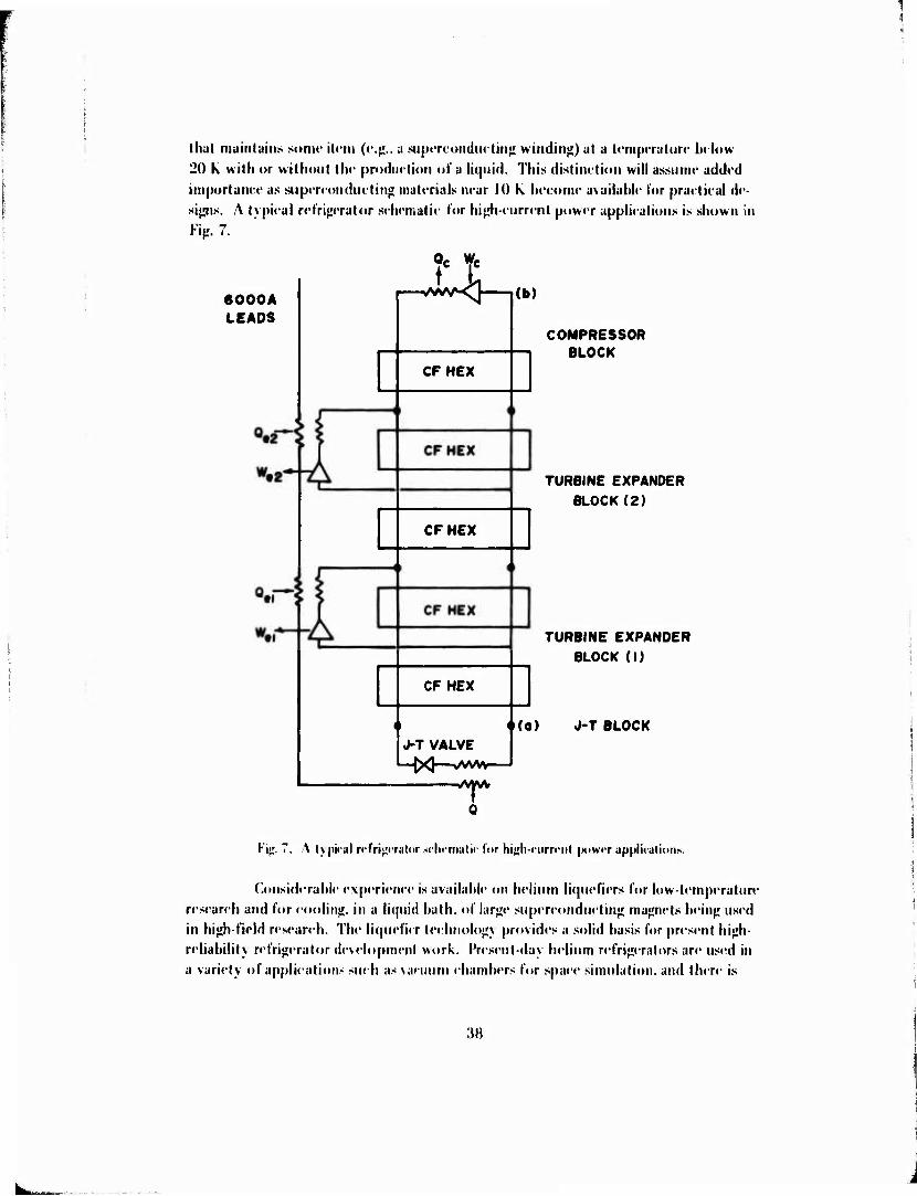
thai maintuiiis sump ilcm (i'.};.. a suptTcuiiductin^ winding) at a h'mpt-ratun- b« low
20 K with or wiltiont ill«' production of a liquid. Thus distinction will assume added
importance as .supercunduetin" materials near 10 k become available for practical de-
signs. A typical refrigerator sehematic for hii;h-current power applications is shown in
Kip. 7.
6000A LEADS
Qr VK wc c
ww»-^
CFHEX
CFHEX
CFHEX
J-T VALVE
WVW
(b)
COMPRESSOR BLOCK
TURBINE EXPANDER
BLOCK(2)
TURBINE EXPANDER
BLOCK (I)
o(o) J-T BLOCK
Kic;. 7. A typiral n'frip'falwr sclirmalic for hijrli-rurri'nl |M>W»T upidicalions.
Considerable experience is available on helium liquefiers for low-temperature
research and for moling, in a liquid bath, of lar«je supereondiietin<! majjnets beiii}; used
in high-field research. The liqucfi« r teehnologv provides a solid basis for present high-
reliability refrigerator development work. Present-day helium refrigerators are used in
a variety of applications such as vacuum chambers for space simulation, and there is
3H
i

in reusing devcloptu -nt uclivity. However, al (ircsml. n-liuhlt- lu-liniu rt'l'ri^crutiori lor
(he load profiles chanuti'ristir of siiprrrotidiKlin*! povsiT iH|(ii[)in<'iil is not availabk'.
37. Limitations of Existing Terlinulo^y. Military rrfri^t-rali«»!! f(|iii|im(,nt lor
pulsed supfrcoriductiii^ roils, MUD ma^iH'ls. or rotating «'iier^y «onv^-rtcrs iisiii}i SUJHT-
roiidurtin^ cxc-italion will have special recpiirements. It is in the area of eiiuineering
for military requiremeiils that many limitations exist (e.g., eompressor leelmology,
transportahility, final heat rejeetion to air). Equipment must he moliile and reliahle,
without the need for complex field maintenance. Integration of the dcsi^il of the
refrigerator with the equipntent hein^ cooled will he essential to rneelin;: military
needs; however, little, if any, experience is availahle in the area of integration. For
the majority of applications where high current must he conducted to a low-tempera-
ture region, iiile^ration of equipment which allows inlcreeplion of thermal loads at
intermediate t. nqieraturcs will he important to si/e and efficiency. Factors of .1 to 1(1
are imolved as regards hulk and power input, (lool-down times and overload perfor-
mance «if such systems cannot he easilv estimated and design procedures need to he
developed.
Sixc, weight, or input power of refrigeration equipment may offset the ad-
vantag)* of using cryogenics in some cases. Kxistiitg refrigerators having their main load
at 4..'> K can he roughly sized using the following rules:
a. KM) kg/watt refrigeration.
h. 0.1.*) cuhic meter/wait refrigeration.
c. Input power approximately HMMIW per VV of refrigeration. Since cool-
down time restrictions, heat rejection temperature, relialiility requirements, and upper
stage loads can result in order of magnitude errors, the altove rides should IM- applied
with caution. In many applications. It will he possilde to eireumvent apparent si/e und
efficiency limitations when integrated design procedures are developed.
\nother current limitation is reliuhility . IVesetit technology is hased on
minimum capital cost for fixed-site installation. The primary application of the
refrigerators is in high-technology environments where regular mainleiiancc is almost
universally [»erformed in an expert manner, and continuous operation of equipment
is not essential. I'or these reasons, components stiitahle for long-life and reliahle field
refrigerators have not heen needed and have not heen developed. Militärs develop
rnenl support is required to fulfill the special military needs lor lran-|)ortaltilily . long
life, and low niainlcnance.
:w

38. Pacing Prublems. There is no single purumoiml proliletn imiH-ciiti^ tJevelop-
riM-nl of refri<j«'rators Ui ineel Army requin'nu'iil.s; iiuh-ed, liiere appear lo l»e several
vialtle alieruative iipproaehes. Il«»wever. effort will have to he expendetl lo uiurover
anil solve a myriad of pruhlems eaused i»y the speeifie needs of the military. Impor-
tant areas in which exploratory development is needed are integration of refrigeration
equipment into overall designs: provisions for upper stage loads and transient loads;
and development of eornpaet, reliahle eomponents for long-term operation with mini-
mum maintenance. Arnhient temperature helium compressors represent the compo-
nent area most in need of development. The compressor and associated heat rejection
equipment account for a large part of Ihe hulk of the entire refrigeration system. Piston
compressors arc commonly used and are hidky. INon-luhrieated piston compressors
have a mean lime hetween maintenance (MTHM) of about 2500 hours, while lahyrinth
seal oil liihricaled compressors have ahoul HOO0 hours MTIiM. To meet si/c and
weight requirements for military applications, more compact compressors will he
needed. I)e|)ending on power level, helical screw cofnprcssors and turhomachinc com-
pressors have to he evaluated. Screw compressors arc e\lrapolated lo operate 40.000
hours MTIiM. and lurhomachinery comhincs compactness with potential rcliahility.
39. Technology Korecast. Applied supemmduetivily is rapidly coming of age,
hringin<r with it the need for helium refrigeration technology. During the next decade,
the commercial pressure to improve existing equipment, introduce new items, and
realize cost savings will accelerate the introduction of superconductivity and the pace
of refrigerator development. Supcrconductin" systems will he designed to operate at
temperatures ahove the critical point of liquid helium, and integrated refrigeration will
replace tanked cryogens within 10 to 12 years.
40. Current DOI) Programs. The discussion will he limited to helium refrigera-
tion as defined in paragraph 36 and will not treat higher temperature eryogenie cooling
of sensors. The Army at MKKIH! has an (»ngoin«; program of lurhomachinery develop-
ment for helium refrigeration, started in l%M, with a ioial funding level to date of
SI.000K. Other Army interest has heen limited to classified pa|»cr studies of helium
refrigeration applied to special nun-power equipment. The Navy sponsored an Industry-
(iovcrnment conference on cryogenic refrigeration in April 1972 to discuss their needs
and to announce an intentioit to start a refrigerator program. Such work is an essential
part of the Navy s planned development of superconducting electric drives for ships'
propulsion. \n in-house effort is now in progress at M{ I, and MJS. WiV \ has initialed
a program with (icneral Kleclrie which, lo date, has heen limiled lo a paper study and
which will Mipporl the Navy's plans in superconducting machinery . Inilial reports arc
not \cl availalile. The \ir I'orce is s|M)nsoring low-power helium refrigeration work
lor unaileiided sensttr apidicalioiis. Tin' \ir Korcc work include:- Vuilleumier develop-
ment h\ Hughes and North \mericati Philip-: rolary free pi-ton devclxqimcnl hy
Arthur I). Little: and turhomachinery developmenl at (icneral Klectric. The latter
40

t-ffurt is U'inn torniinated, ufter an t-xpt'nditun* (if $2(M)ÜK. apparently due to funding liinilations. It is undcrstuud that plans have been made for in-huuse completion and evaluation of this equipment, ineluding low-temperature tests.
41. Other Programs. MiShas an ongoing in-house effort in helium refrigeration as well as a substantial haekground in hydrogen work. Both Kngland and Japan have reported work on turhoexpauders for helium refrigeration in the open literature; how-
ever, the details of their eurrent refrigeration development programs are not known. The British Navy has reported in-house work on a multi-stage regenerative turboeom- pressor for helium using a single wheel. The present state of this development is not known.
42. Priorities.
a. Im hide integrated refrigeration in future supereondueting equipment ilevelopment.
b. Ihiild a system to provide o|terating e\|)erienee with turborefrigeration
eotnponent and inSermittent loads and heavy upper stage loads.
e. Fund eomponenl development of umbienl temperature helium com-
pressor equipment.
d. Develop refrigerator interl'aee and heat-transfer techniques for vapor cooling of supereondticthig windings.
41