Embed Size (px)
Citation preview
V.W.S. Chani.
Intersatellite Optical HeterodyneCommunication Systems
High-capacity intersatellite communication crosslinks will allow more efficient andreliable operation of military and commercial satellite systems. High-speed opticalcrosslinks can serve as a key building element of an interconnected space-based communication system for military applications. A network such as this would provideimmediate communication among satellites. eliminating the need for ground-basedrelay stations and expensive worldwide ground tracking networks. which would greatlyimprove the efficacy and reduce the vulnerability ofexisting satellite systems. Crosslinkscan also provide connectivity for commercial global satellite communication systemsand for deep-space applications. Optical heterodyne communication systems usingsemiconductor lasers offer small-aperture. modest-weight. low-power. pOint-to-pointcrosslink packages. characteristics that are suitable for the envisioned applications.System research and development performed at Lincoln Laboratory permits the implementation of an efficient optical crosslink based on readily aVailable. state-of-the-artdevices and technology.
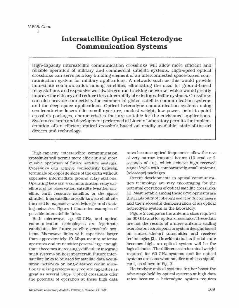
High-capacity intersatellite communicationcrosslinks will permit more efficient and morereliable operation of future satellite systems.Crosslinks can achieve connectivity betweenterminals on opposite sides of the earth withoutexpensive intermediate ground relay stations.Operating between a communication relay satellite and an observation satellite (weather satellite, earth resource satellite. or the spaceshuttle). intersatellite crosslinks also eliminatethe need for expensive worldwide ground tracking networks. Figure 1 illustrates examples ofpossible intersatellite links.
Both microwave, ego 60-GHz, and opticalcommunication technologies are legitimatecandidates for future satellite crosslink systems. Microwave links with capacities largerthan approximately 10 Mbps require antennaapertures and transmitter powers large enoughthat it becomes increasingly difficult to integratesuch systems on host spacecraft. Future intersatellite links to be used for satellite data acquisition networks or long-distance communication trunking systems may require capacities asgreat as several Gbps. Optical crosslinks offerthe potential of operation at these high data
The Lincoln Laboratory Journal, Volume 1, Number 2 (1988)
rates because optical frequencies allow the useof very narrow transmit beams (lO !1rad or 2seconds of arc), which achieve high receivedsignal levels with comparatively small antenna(telescope) packages.
Recent developments in optical communication technology are very encouraging for thepotential operation ofoptical satellite crosslinks[1]. Most notable among these developments arethe availability ofcoherent semiconductor lasersand the successful demonstration of an opticalheterodyne system in the laboratory.
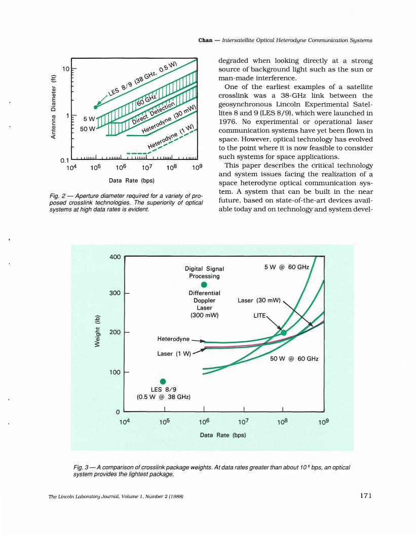
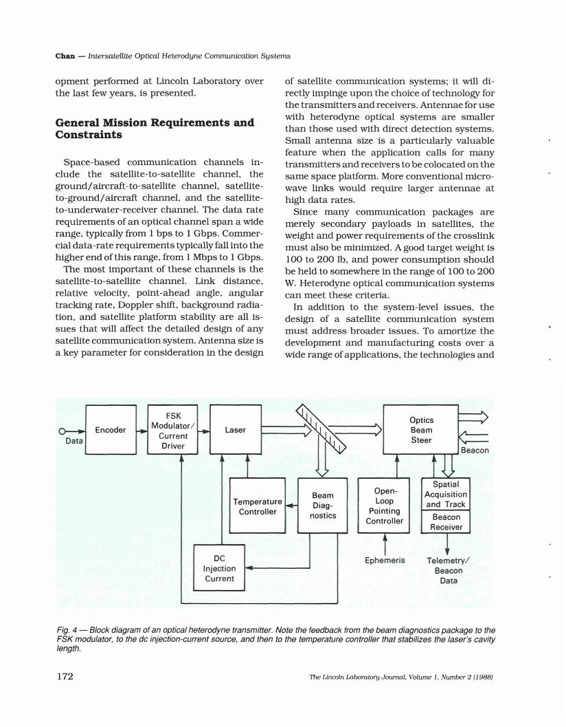
Figure 2 compares the antenna sizes requiredfor 60 GHz and for optical crosslinks. These dataare not the results of a mere antenna scalingexercisebutcorrespond to system designs basedon state-of-the-art transmitter and receivertechnologies [2]. It is evidentthatas the data ratebecomes high, an optical system will be thelogical choice. The differences in terminal weightrequired for 60-GHz systems and for opticalsystems are somewhat smaller and less significant, as shown in Fig. 3.
Heterodyne optical systems further boost theadvantage held by optical systems at high datarates because a heterodyne system requires
169
Chan - Intersatellite Optical Heterodyne Communication Systems
Fig. 1- This crosslink can allow any of the spacecraft to communicate with another one without using unwieldyground relaystations.
even smaller aperture sizes than direct detection systems (Fig. 2). This small aperture size ispermitted by the nearly quantum-limited performance available from heterodyne detectionsystems. Direct detection systems, on the otherhand, are usually limited by avalanche photodetector excess noise, background noise, andamplifier thermal noise. Compactness, highpower conversion efficiency (prime-to-opticaloutput-power conversion efficiency -20%), andsingle-frequency operation make the GaAlAslaser a good candidate for the laser source in aheterodyne system. At the GaAlAs wavelength
170
region (0.8 11m), the sensitivity of a heterodynesystem can be higher than a direct detectionsystem by 15 dB.
Another advantage of a heterodyne opticalsystem over a direct detection optical system isthat it allows narrowband (-1 GHz) spectralfJltering to be performed at the heterodynereceiver's intermediate frequency. Direct detection systems, on the other hand, have to relyentirely on optical fJlters for background lightrejection. These fJlters are typically severalangstroms (-100-to-500 GHz) wide, and the direct detection receiver's sensitivity is further
The Lincoln Laboratory Journal. Volume 1. Number 2 (1988)
Chan - Intersatellite Optical Heterodyne Communication Systems
10
.:::...(1)
Q)Eco0coc::c::(1)...c::~
O. 1 L....I....L.U.w.Ll--L...L.U.Iw.LL....I-L.l.LLw.L....J...JU-l.LWI.....L.I...l.IlJ,W
104
Data Rate (bps)
Fig. 2 - Aperture diameter required for a variety of proposed crosslink technologies. The superiority of opticalsystems at high data rates is evident.
degraded when looking directly at a strongsource of background light such as the sun orman-made interference.
One of the earliest examples of a satellitecrosslink was a 38-GHz link between thegeosynchronous Lincoln Experimental Satellites 8 and 9 (LES 8/9), which were launched in1976. No experimental or operational lasercommunication systems have yet been flown inspace. However. optical technology has evolvedto the point where it is now feasible to considersuch systems for space applications.
This paper describes the critical technologyand system issues facing the realization of aspace heterodyne optical communication system. A system that can be built in the nearfuture. based on state-of-the-art devices available today and on technology and system devel-
400
Digital SignalProcessing
•300 DifferentialDopplerLaser
:0 (300 mW)
1: 2000)
'Q) Heterodynes:Laser (1 W)
100
•LES 8/9(0.5 W @ 38 GHz)
0
104 105 106 107 108 109
Data Rate (bps)
Fig. 3 - A comparison of crosslink package weights. At data rates greater than about 10 8 bps, an opticalsystem provides the lightest package.
The Lincoln Laboratory Journal. Volume 1. Number 2 (J 988) 171
Chan - IntersateUite Optical Heterodyne Communication Systems
opment performed at Lincoln Laboratory overthe last few years. is presented.
General Mission Requirements andConstraints
Space-based communication channels include the satellite-to-satellite channel, theground/aircraft-to-satellite channel, satelliteto-ground/aircraft channel. and the satelliteto-underwater-receiver channel. The data raterequirements of an optical channel span a widerange. typically from 1 bps to 1 Gbps. Commercial data-rate requirements typically fall into thehigher end of this range. from 1 Mbps to 1 Gbps.
The most important of these channels is thesatellite-to-satellite channel. Link distance.relative velocity. point-ahead angle. angulartracking rate. Doppler shift. background radiation. and satellite platform stability are all issues that will affect the detailed design of anysatellite communication system. Antenna size isa key parameter for consideration in the design
of satellite communication systems; it will directly impinge upon the choice of technology forthe transmitters and receivers. Antennae for usewith heterodyne optical systems are smallerthan those used with direct detection systems.Small antenna size is a particularly valuablefeature when the application calls for manytransmitters and receivers to be colocated on thesame space platform. More conventional microwave links would require larger antennae athigh data rates.
Since many communication packages aremerely secondary payloads in satellites. theweight and power requirements of the crosslinkmust also be minimized. A good target weight is100 to 200 lb. and power consumption shouldbe held to somewhere in the range of 100 to 200W. Heterodyne optical communication systemscan meet these criteria.
In addition to the system-level issues. thedesign of a satellite communication systemmust address broader issues. To amortize thedevelopment and manufactUring costs over awide range of applications. the technologies and
Telemetry/Beacon
Data
SpatialAcquisitionand Track
BeaconReceiver
OpticsBeamSteer
L-.........-----r---r~ Beacon
>
OpenLoop
PointingController
Ephemeris
FSK~ Encoder r. Modulator/
~ Laser...... CurrentData
Driver
BeamTemperature
~ Diag-Controller nostics
DCInjectionCurrent
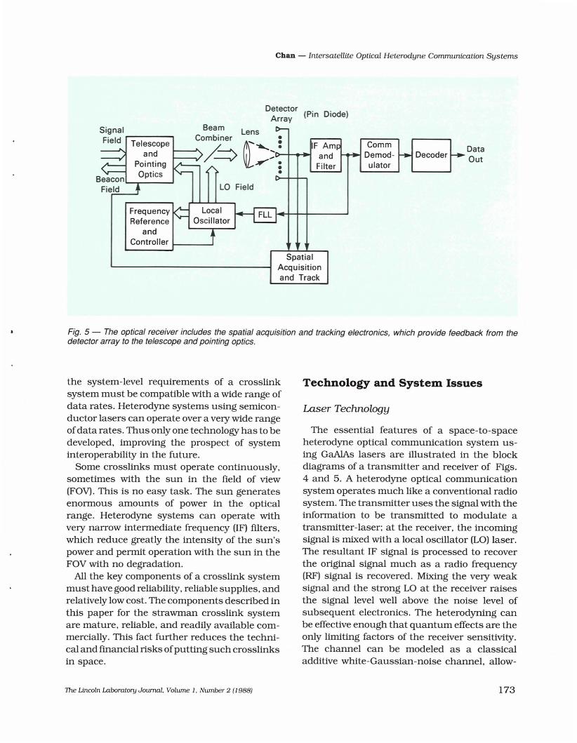
Fig. 4 - Block diagram of an optical heterodyne transmitter. Note the feedback from the beam diagr:.ostics packa~e to t~e
FSK modulator. to the dc injection-current source, and then to the temperature controller that stabilizes the laser s cavitylength.
172 The Lincoln Laboratory Journal. Volume 1. Number 2 (1988)
Chan - Intersatellite Optical Heterodyne Communication Systems
DetectorArray (Pin Diode)
DataOutDecoder
CommDemodulator
SpatialAcquisitionand Track
LO Field
Signal Beam Lens
Field ,----:__c,,,o/; ~'>t>:.:-+...-I~ Fa~;W- Filter
•Beacon~~__~
Field
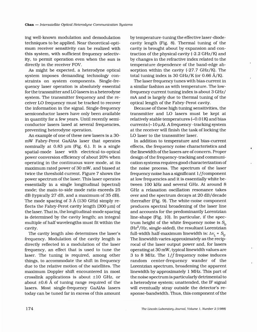
Fig. 5 - The optical receiver includes the spatial acquisition and tracking electronics, which provide feedback from thedetector array to the telescope and pointing optics.
the system-level requirements of a crosslinksystem must be compatible with a wide range ofdata rates. Heterodyne systems using semiconductor lasers can operate over a very wide rangeofdata rates. Thus only one technology has to bedeveloped, improving the prospect of systeminteroperability in the future.
Some crosslinks must operate continuously,sometimes with the sun in the field of view(FOY). This is no easy task. The sun generatesenormous amounts of power in the opticalrange. Heterodyne systems can operate withvery narrow intermediate frequency (IF) filters,which reduce greatly the intensity of the sun'spower and permit operation with the sun in theFOV with no degradation.
All the key components of a crosslink systemmust have good reliability, reliable supplies, andrelatively low cost. The components described inthis paper for the strawman crosslink systemare mature, reliable, and readily available commercially. This fact further reduces the technical and financial risks ofputting such crosslinksin space.
Technology and System Issues
Laser Teclmology
The essential features of a space-to-spaceheterodyne optical communication system using GaAlAs lasers are illustrated in the blockdiagrams of a transmitter and receiver of Figs.4 and 5. A heterodyne optical communicationsystem operates much like a conventional radiosystem. The transmitter uses the signal with theinformation to be transmitted to modulate atransmitter-laser; at the receiver, the incomingsignal is mixed with a local oscillator (LO) laser.The resultant IF signal is processed to recoverthe original signal much as a radio frequency(RF) signal is recovered. Mixing the very weaksignal and the strong LO at the receiver raisesthe signal level well above the noise level ofsubsequent electronics. The heterodyning canbe effective enough that quantum effects are theonly limiting factors of the receiver sensitivity.The channel can be modeled as a classicaladditive white-Gaussian-noise channel, allow-
The Lincoln Laboratory Journal. Volume 1, Number 2 (1988) 173
Chan - Intersatellite Optical Heterodyne Communication Systems
ing well-known modulation and demodulationtechniques to be applied. Near theoretical-optimum receiver sensitivity can be realized withthis system, with sufficient frequency selectivity, to permit operation even when the sun isdirectly in the receiver FOV.
As might be expected, a heterodyne opticalsystem imposes demanding technology constraints on system components. Single-frequency laser operation is absolutely essentialfor the transmitter and LO lasers in a heterodynesystem. The transmitter frequency and the receiver LO frequency must be tracked to recoverthe information in the signal. Single-frequencysemiconductor lasers have only been availablein quantity for a few years. Until recently semiconductor lasers lased at several frequencies,preventing heterodyne operation.
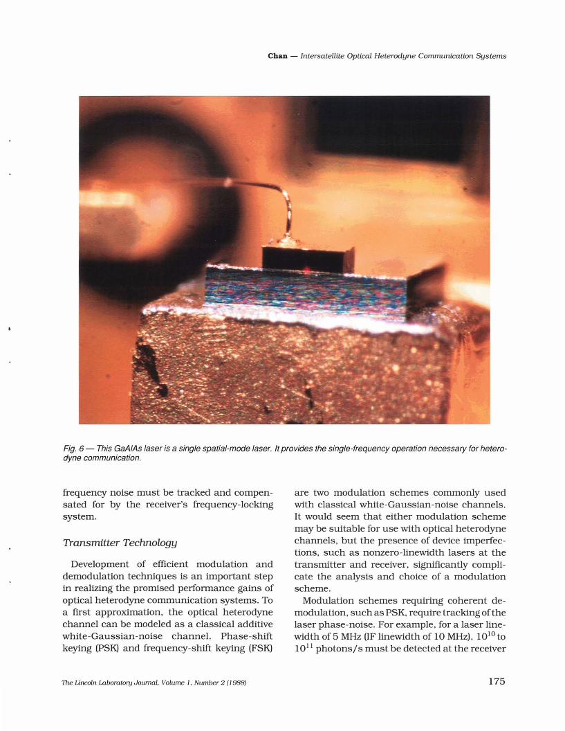
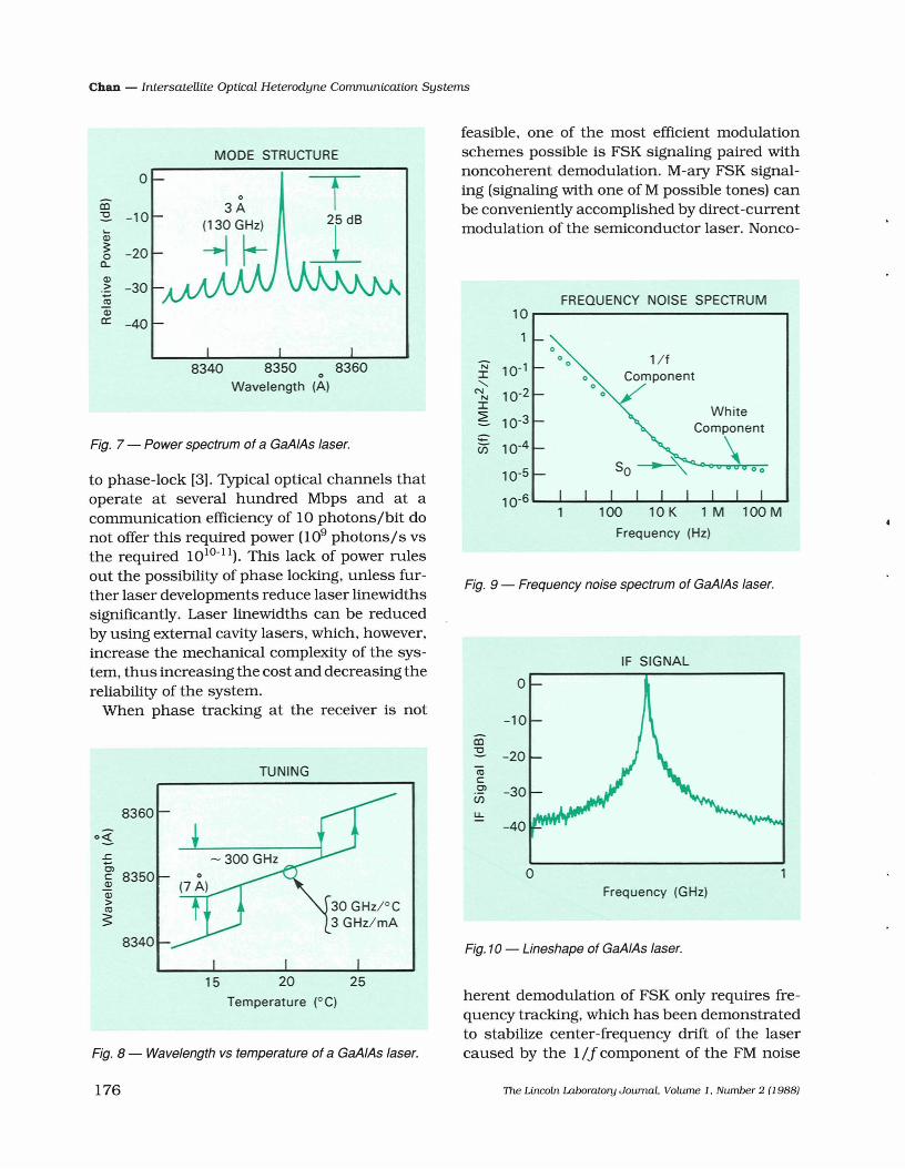
An example of one of these new lasers is a 30mW Fabry-Perot GaAlAs laser that operatesnominally at 0.83 ~m (Fig. 6.). It is a singlespatial-mode laser with electrical-to-opticalpower conversion efficiency of about 20% whenoperating in the continuous wave mode, at itsmaximum rated power of 30 mW, and biased attwice the threshold current. Figure 7 shows thepower spectrum of the laser. This laser operatesessentially in a single longitudinal (spectral)mode; the main-to-side mode ratio exceeds 25dB (typically 27 dB, and a maximum of 35 dB).The mode spacing of 3 A (130 GHz) simply reflects the Fabry-Perot cavity length (300 ~m) ofthe laser. That is, the longitudinal-mode spacingis determined by the cavity length; an integralmultiple of half wavelengths must fit within thecavity.
The cavity length also determines the laser'sfrequency. Modulation of the cavity length isdirectly reflected in a modulation of the laserfrequency, an effect that is used to tune thelaser. The tuning is required, among otherthings, to accommodate the shift in frequencydue to the relative motion of the satellites. Themaximum Doppler shift encountered in mostcrosslink applications is about ±10 GHz, orabout ±0.6 A of tuning range reqUired of thelasers. Most single-frequency GaAlAs laserstoday can be tuned far in excess of this amount
174
by temperature-tuning the effective laser-diodecavity length (Fig. 8). Thermal tuning of thecavity is brought about by expansion and contraction of the physical cavity (-2.2 GHzIK) andby changes in the refractive index related to thetemperature dependence of the band-edge absorption within the cavity (-27.7 GHzIK). Thetotal tuning index is 30 GHzIK (or 0.66 A/K).
The laser frequency tunes with bias current ina similar fashion as with temperature. The lowfrequency current tuning index is about 3 GHzIrnA and is largely due to thermal tuning of theoptical length of the Fabry-Perot cavity.
Because of these high tuning sensitivities, thetransmitter and LO lasers must be kept atrelatively stable temperatures (-0.01 K) and biascurrents (-10 ~A). A frequency -tracking systemat the receiver will finish the task of locking theLO laser to the transmitter laser.
In addition to temperature and bias-currenteffects, the frequency noise characteristics andthe linewidth ofthe lasers are of concern. Properdesign of the frequency-tracking and communication systems requires good characterization ofthe noise process. The spectrum of the laserfrequency noise has a significant 1Ifcomponentat low frequencies and it is essentially white between 100 kHz and several GHz. At around 8GHz a relaxation oscillation resonance takesover and the spectrum decays at 20 dB I decadethereafter (Fig. 9). The white-noise componentproduces spectral broadening of the laser lineand accounts for the predominantly Lorentzianline-shape (Fig. 10). In particular, if the spectrum height of the white frequency noise is So(Hz2 /Hz, single-sided), the resultant Lorentzianfull-width half-maximum linewidth is: ~VL = So'The linewidth varies approximately as the reciprocal of the laser output power and, for lasersoperating at 30 mW, typicallinewidth values are3 to 8 MHz. The 1If frequency noise inducesrandom center-frequency wander of theLorentzian spectrum, broadening the apparentlinewidth by approximately 1 MHz. This part ofthe noise spectrum is particularly detrimental toa heterodyne system; unattended, the IF signalwill eventually stray outside the detector's response-bandwidth. Thus, this component ofthe
The Lincoln Laboratory Journal. Volume 1. Number 2 (l988)
Chan - Intersatellite Optical Heterodyne Communication Systems
Fig. 6 - This GaAIAs laser is a single spatial-mode laser. It provides the single-frequency operation necessary for heterodyne communication.
frequency noise must be tracked and compensated for by the receiver's frequency-lockingsystem.
Transmitter Technology
Development of efficient modulation anddemodulation techniques is an important stepin realizing the promised performance gains ofoptical heterodyne communication systems. Toa fIrst approximation, the optical heterodynechannel can be modeled as a classical additivewhite-Gaussian-noise channel. Phase-shiftkeying (PSK) and frequency-shift keying (FSK)
The Uncoln Laboratory Journal. Volume 1. Number 2 (l988)
are two modulation schemes commonly usedwith classical white-Gaussian-noise channels.It would seem that either modulation schememay be suitable for use with optical heterodynechannels, but the presence of device imperfections, such as nonzero-linewidth lasers at thetransmitter and receiver, signillcantly complicate the analysis and choice of a modulationscheme.
Modulation schemes requiring coherent demodulation, such as PSK, require tracking ofthelaser phase-noise. For example, for a laser linewidth of 5 MHz (IF linewidth of 10 MHz). 1OIO tolOll photons/s must be detected at the receiver
175
Chan - Intersatellite Optical Heterodyne Communication Systems
1 M 100 M
WhiteComponent
10 K
1IfComponent
Frequency (Hz)
o
100
oo
oo
o
10
1
N 10-'I"-
N 10-2NI~ 10-3
-- 10-4Cii
10-5
10-6
o
-10
FREQUENCY NOISE SPECTRUM
IF SIGNAL
Fig. 9 - Frequency noise spectrum of GaAlAs laser.
8350 8360o
Wavelength (A)8340
MODE STRUCTURE
0 TCD~ -10 25 dBCo
~~ -200Cl..
Q)
.::: -30'iiiQ)
a:: -40
feasible, one of the most efficient modulationschemes possible is FSK signaling paired withnoncoherent demodulation. M-ary FSK signaling (signaling with one of M possible tones) canbe conveniently accomplished by direct-currentmodulation of the semiconductor laser. Nonco-
Fig. 7 - Power spectrum of a GaAIAs laser.
to phase-lock [3]. Typical optical channels thatoperate at several hundred Mbps and at acommunication efficiency of 10 photons/bit donot offer this reqUired power (l09 photons/s vsthe reqUired 1010-11). This lack of power rulesout the possibility of phase locking, unless further laser developments reduce laser linewidthssignificantly. Laser linewidths can be reducedby using external cavity lasers, which, however,increase the mechanical complexity of the system, thus increasing the cost and decreasing thereliability of the system.
When phase tracking at the receiver is not
TUNING
8360
0<1:
..c0,
8350c~Q)>ttl
~
8340
ttlc.2>(/)
u.
oFrequency (GHz)
Fig. 10 - Lineshape of GaAIAs laser.
15Temperature (OC)
Fig. 8 - Wavelength vs temperature of a GaAIAs laser.
herent demodulation of FSK only requires frequency tracking, which has been demonstratedto stabilize center-frequency drift of the lasercaused by the 1/J component of the FM noise
176 The Lincoln Laboratory Journal. Volume 1. Number 2 (1988)
Chan - Intersatellite Optical Heterodyne Communication Systems
spectrum to a few MHz rms error [3.4]. Operational use of such a system has been shown tocause negligible performance degradation [5].
A GaAlAs laser can be frequency-modulatedthrough direct injection-current modulation[6.7], thereby providing both a frequency-modulated transmitter laser and a frequency-agileLO. If an FSK transmitter is to be realized bydirect injection-current modulation of a semiconductor diode laser. its modulation characteristics throughout the spectrum of the modulation waveform must be uniform. In particular.for an FSKinjection-current modulator. operating in the 100-Mbps region. the laser must
Demodulated 4-ary FSK Data(20 ns/div)
Optical Power Spectrum(200 MHz/div)
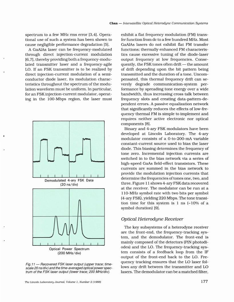
Fig. 11 - Recovered FSK laser output (upper trace; timescale 20 ns/div) and the time-averaged opticalpowerspectrum of the FSK laser output (lower trace; 200 MHz/div).
The Lincoln Laboratory Journal. Volume 1. Number 2 (1988)
exhibit a flat frequency modulation (FM) transfer function from dc to a few hundred MHz. MostGaAlAs lasers do not exhibit flat FM transferfunctions; thermally enhanced FM characteristics cause excessive tuning of the diode-laseroutput frequency at low frequencies. Consequently. the FSK tones often drift - the amountof drift depending upon the bit pattern beingtransmitted and the duration of a tone. Uncompensated. this thermal frequency drift can severely degrade communication-system performance by spreading tone energy over a widebandwidth. thus increasing cross talk betweenfrequency slots and creating data-pattern-dependent errors. A passive equalization networkthat significantly reduces the effects of low-frequency thermal FM is simple to implement andrequires neither active electronic nor opticalcomponents [8].
Binary and 4-ary FSK modulators have beendeveloped at Lincoln Laboratory. The 4-arymodulator consists of a 0-to-200-mA variableconstant-current source used to bias the laserdiode. This biasing determines the frequency oftone zero. Incremental injection currents areswitched in to the bias network via a series ofhigh-speed GaAs field-effect transistors. Thesecurrents are' summed in the bias network toprovide the modulation injection currents thatdetermine the frequencies oftones one. two. andthree. Figure 11 shows 4-ary FSK data recoveredat the receiver. The modulator can be run at allO-MHz symbol rate with two bits per symbol(4-ary FSKj, yielding 220 Mbps. The tone transition time for this system is 1 ns (-10% of asymbol duration) [9].
Optical Heterodyne Receiver
The key subsystems of a heterodyne receiverare the front-end. the frequency-tracking system. and the demodulator. The front-end ismainly composed of the detectors (PIN photodiodes) and the LO. The frequency-tracking system consists of a feedback loop from the IFoutput of the front-end back to the LO. Frequency tracking ensures that the LO laser follows any drift between the transmitter and LOlasers. The demodulator can be a matched filter.
177
Chan - Intersatellite Optical Heterodyne Communication Systems
LocalOscillator
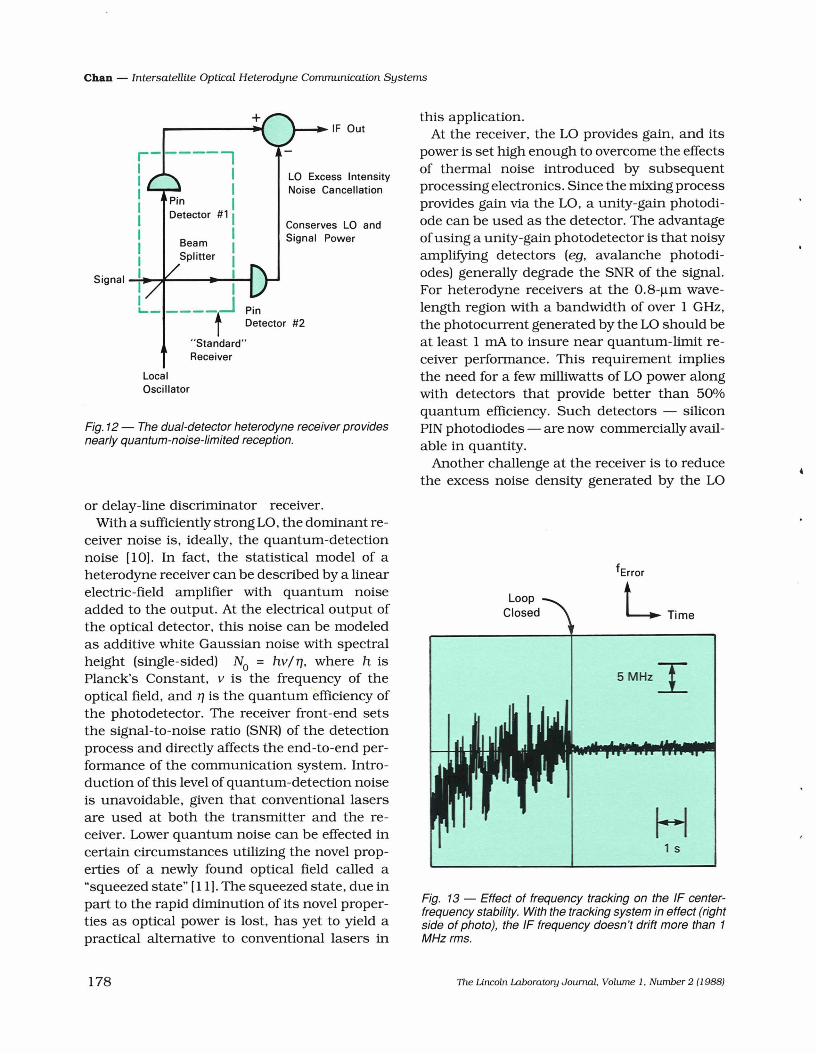
Fig. 12 - The dual-detector heterodyne receiver providesnearly quantum-noise-iimited reception.
Conserves LO andSignal Power
this application.At the receiver, the LO provides gain, and its
power is set high enough to overcome the effectsof thermal noise introduced by subsequentprocessing electronics. Since the mixing processprovides gain via the LO, a unity-gain photodiode can be used as the detector. The advantageof using a unity-gain photodetector is that noisyamplifying detectors (eg, avalanche photodiodes) generally degrade the SNR of the signal.For heterodyne receivers at the 0.8-llm wavelength region with a bandwidth of over 1 GHz,the photocurrent generated by the LO should beat least 1 rnA to insure near quantum-limit receiver performance. This requirement impliesthe need for a few milliwatts of LO power alongwith detectors that provide better than 50%quantum efficiency. Such detectors - siliconPIN photodiodes - are now commerciallyavailable in quantity.
Another challenge at the receiver is to reducethe excess noise density generated by the LO
IF Out
LO Excess IntensityNoise Cancellation
r------,I 1I 1I Pin II Detector #1 II 1I Beam II Splitter 1
Signal -i-I:.....,,:-----l_....I-I
L_ ----f..J PinDetector #2
"Standard"Receiver
+
or delay-line discriminator receiver.With a sufficiently strong LO, the dominant re
ceiver noise is, ideally, the quantum-detectionnoise (10). In fact, the statistical model of aheterodyne receiver can be described by a linearelectric-field amplifier with quantum noiseadded to the output. At the electrical output ofthe optical detector, this noise can be modeledas additive white Gaussian noise with spectralheight (single-sided) No = hV/1], where h isPlanck's Constant, v is the frequency of theoptical field, and 1] is the quantum efficiency ofthe photodetector. The receiver front-end setsthe signal-to-noise ratio (SNR) of the detectionprocess and directly affects the end-to-end performance of the communication system. Introduction of this level of quantum-detection noiseis unavoidable, given that conventional lasersare used at both the transmitter and the receiver. Lower quantum noise can be effected incertain circumstances utilizing the novel properties of a newly found optical field called a"squeezed state" [11). The squeezed state, due inpart to the rapid diminution of its novel properties as optical power is lost, has yet to yield apractical alternative to conventional lasers in
LTime
5MHz I
H1 s
Fig. 13 - Effect of frequency tracking on the IF centerfrequency stability. With the tracking system in effect (rightside of photo), the IF frequency doesn't drift more than 1MHzrms.
178 The Lincoln Laboratory Journal. Volume 1. Number 2 (19881
Chan - Intersatellite Optical Heterodyne Communication Systems
(c)
B
(b)
AB
(a)
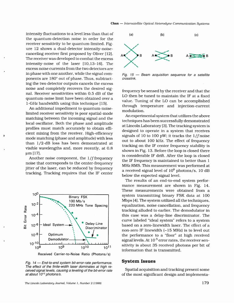
Fig. 15 - Beam acquisition sequence for a satellitecrosslink.
frequency be sensed by the receiver and that theLO then be tuned to maintain the IF at a fixedvalue. Tuning of the LO can be accomplishedthrough temperature and injection-currentmodulation.
An experimental system that utilizes the abovetechniques has been successfully demonstratedat Lincoln Laboratory (3). The tracking system isdesigned to operate in a system that receivessignals of 10 to 100 pW; it tracks the l/jnoiseout to about 100 kHz. The effect of frequencytracking on the IF center frequency stability isshown in Fig. 13. Before the loop is closed thereis conSiderable IF drift. Mter the loop is closedthe IF frequency is maintained to better than 1MHz RMS. This measurement was performed ata received signal level of 108 photons/so 10 dBbelow the expected signal level.
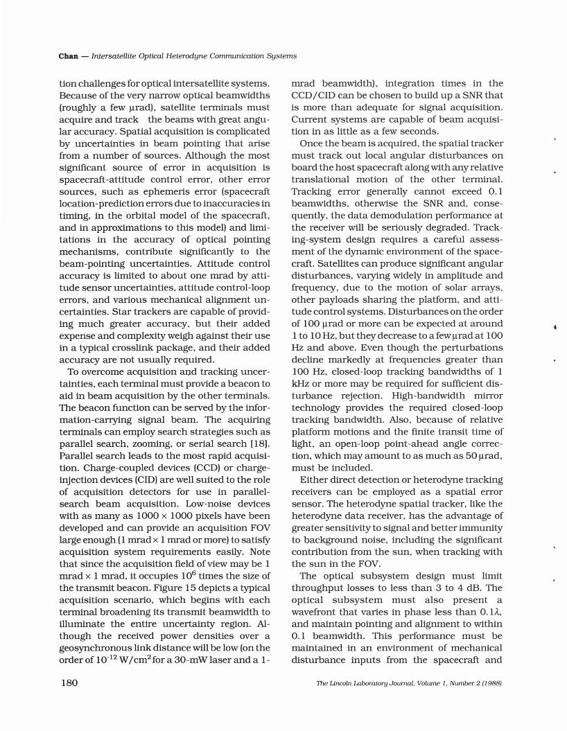
The results of an end-to-end system performance measurement are shown in Fig. 14.These measurements were obtained from asystem transmitting binary FSK data at 100Mbps (4). The system utilized all the techniques,equalization, noise cancellation. and frequencytracking alluded to earlier. The demodulator inthis case was a delay-line discriminator. Thecurve labeled "ideal system" refers to a systembased on a zero-linewidth laser. The effect of anon-zero IF linewidth (-15 MHz) is to level outthe performance to a "floor" at high receivedsignal levels. At 10-5 error rates. the receiver sensitivity is about 35 received photons per bit ofinformation that is transmitted.
A
intensity fluctuations to a level less than that ofthe quantum-detection noise in order for thereceiver sensitivity to be quantum-limited. Figure 12 shows a dual-detector intensity-noisecanceling receiver first proposed by Oliver (12).The receiver was developed to combat the excessintensity-noise of the laser [10,13-16). Theexcess noise currents from the two detectors arein phase with one another, while the signal components are 1800 out of phase. Thus, subtracting the two detector outputs cancels the excessnoise and completely recovers the desired signal. Receiver sensitivities within 0.5 dB of thequantum-noise limit have been obtained over a1-GHz bandwidth using this technique (15).
An additional impediment to quantum-noiselimited receiver sensitivity is poor spatial-modematching between the incoming signal and thelocal oscillator. Both the phase and amplitudeprofiles must match accurately to obtain efficient mixing from the receiver. High-efficiencymode matching (phase and amplitude) with lessthan 1/2-dB loss has been demonstrated atvisible wavelengths and, more recently, at 0.8/lm (17).
Another noise component, the 1/jfrequencynoise that corresponds to the center-frequencyjitter of the laser, can be reduced by frequencytracking. Tracking requires that the IF center
10°Binary FSK.. 100 Mb/s.
10-2 ... 220 MHz Tone SpacingQ) .....ctl .
a:: ..10-4 .... .
0......w... 10-6 IdealaJ
10-8
10-10108 109 1010
Received Carrier-to-Noise Ratio (Photons/s)
Fig. 14 - End-to-end system bit-error-rate perforrr:ance.The effect of the finite-width laser dommates at high received signal levels, causing a leveling of the bit-error rateat about 10'0 photons/so
System Issues
Spatial acquisition and tracking present someof the most significant design and implementa-
The Lincoln Laboratory Journal. Volume 1. Number 2 (1988) 179
Chan - Intersatellite Optical Heterodyne Communication Systems
tion challenges for optical intersatellite systems.Because of the very narrow optical beamwidths(roughly a few ~rad), satellite terminals mustacquire and track the beams with great angular accuracy. Spatial acquisition is complicatedby uncertainties in beam pointing that arisefrom a number of sources. Although the mostsignificant source of error in acquisition isspacecraft-attitude control error, other errorsources, such as ephemeris error (spacecraftlocation-prediction errors due to inaccuracies intiming, in the orbital model of the spacecraft,and in approximations to this model) and limitations in the accuracy of optical pointingmechanisms, contribute significantly to thebeam-pointing uncertainties. Attitude controlaccuracy is limited to about one mrad byattitude sensor uncertainties, attitude control-looperrors, and various mechanical alignment uncertainties. Star trackers are capable of providing much greater accuracy, but their addedexpense and complexity weigh against their usein a typical crosslink package, and their addedaccuracy are not usually required.
To overcome acquisition and tracking uncertainties, each terminal must provide a beacon toaid in beam acquisition by the other terminals.The beacon function can be served by the information-carrying signal beam. The acquiringterminals can employ search strategies such asparallel search, zooming, or serial search [18).Parallel search leads to the most rapid acquisition. Charge-coupled devices (CCD) or chargeinjection devices (CID) are well suited to the roleof acquisition detectors for use in parallelsearch beam acquisition. Low-noise deviceswith as many as 1000 x 1000 pixels have beendeveloped and can provide an acquisition FOVlarge enough (1 mrad x 1 mrad or more) to satisfyacquisition system requirements easily. Notethat since the acquisition field of view may be 1mrad x 1 mrad, it occupies 106 times the size ofthe transmit beacon. Figure 15 depicts a typicalacquisition scenario, which begins with eachterminal broadening its transmit beamwidth toilluminate the entire uncertainty region. Although the received power densities over ageosynchronous link distance will be low (on theorder of 10-12 W/cm2 for a 30-mWlaser and a 1-
180
mrad beamwidth), integration times in theCCD/CID can be chosen to build up a SNR thatis more than adequate for signal acquisition.Current systems are capable of beam acquisition in as little as a few seconds.
Once the beam is acquired, the spatial trackermust track out local angular disturbances onboard the host spacecraft along with any relativetranslational motion of the other terminal.Tracking error generally cannot exceed 0.1beamwidths, otherwise the SNR and, consequently, the data demodulation performance atthe receiver will be seriously degraded. Tracking-system design requires a careful assessment of the dynamic environment of the spacecraft. Satellites can produce significant angulardisturbances, varying widely in amplitude andfrequency, due to the motion of solar arrays,other payloads sharing the platform, and attitude control systems. Disturbances on the orderof 100 ~rad or more can be expected at around1 to 10 Hz, but they decrease to a few ~rad at 100Hz and above. Even though the perturbationsdecline markedly at frequencies greater than100 Hz, closed-loop tracking bandwidths of 1kHz or more may be reqUired for sufficient disturbance rejection. High-bandwidth mirrortechnology provides the reqUired closed-looptracking bandwidth. Also, because of relativeplatform motions and the finite transit time oflight, an open-loop point-ahead angle correction, which may amount to as much as 50 ~rad,
must be included.Either direct detection or heterodyne tracking
receivers can be employed as a spatial errorsensor. The heterodyne spatial tracker, like theheterodyne data receiver, has the advantage ofgreater sensitivity to signal and better immunityto background noise, including the significantcontribution from the sun, when tracking withthe sun in the FOV.
The optical subsystem design must limitthroughput losses to less than 3 to 4 dB. Theoptical subsystem must also present awavefront that varies in phase less than O. U,and maintain pointing and alignment to within0.1 beamwidth. This performance must bemaintained in an environment of mechanicaldisturbance inputs from the spacecraft and
The Lincoln Laboratory Journal. Volume 1. Number 2 (1988)
Chan - Intersatellite Optical Heterodyne Communication Systems
From HeterodyneTracker
PowerSwitching
FrequencyAcqlTrack
~---J Clock
1'----_
RECEIVER MODULE
Beam SpoilOptics
Polarizationr-~Li:-n-ea-r'"':'/" Diplexer
Circular b:::::::N;=:=t-"'Be~~l=~~=::!1PolarizationConversion
XmtrPoint-Ahead
Mirror
LOS XmtrPointingDetector
XmtrDiagnostic
HighBandwidth
Optics
BeamExpander
Telescope 0 .ptlCS
OPTICAL MODULE
CoarsePointingMirror
TRANSMITTER MODULE ELECTRICAL MODULE
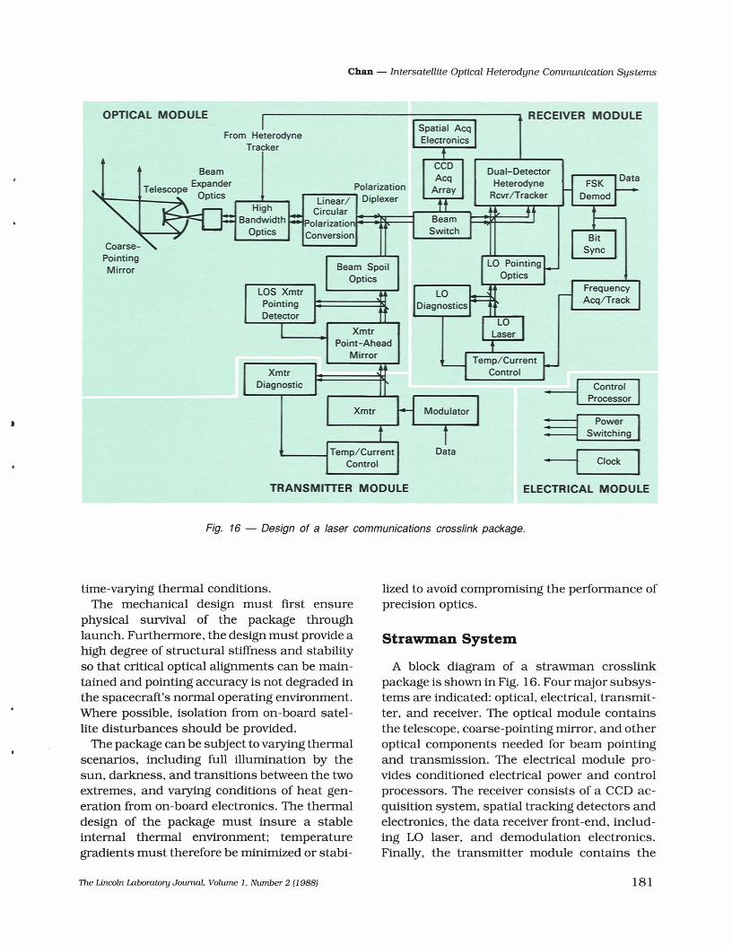
Fig. 16 - Design of a laser communications crosslink package.
time-varying thennal conditions.The mechanical design must first ensure
physical survival of the package throughlaunch. Furthennore. the design must provide ahigh degree of structural stiffness and stabilityso that critical optical alignments can be maintained and pointing accuracy is not degraded inthe spacecraft's nonnal operating environment.Where possible. isolation from on-board satellite disturbances should be provided.
The package can be subject to varying thennalscenarios. including full illumination by thesun. darkness, and transitions between the twoextremes, and varying conditions of heat generation from on-board electronics. The thennaldesign of the package must insure a stableinternal thennal environment; temperaturegradients must therefore be minimized or stabi-
lized to avoid compromising the perfonnance ofprecision optics.
Strawman System
A block diagram of a strawman crosslinkpackage is shown in Fig. 16. Four major subsystems are indicated: optical, electrical. transmitter, and receiver. The optical module containsthe telescope. coarse-pointing mirror. and otheroptical components needed for beam pointingand transmission. The electrical module provides conditioned electrical power and controlprocessors. The receiver consists of a CCO acquisition system. spatial tracking detectors andelectronics, the data receiver front-end. including LO laser, and demodulation electronics.Finally, the transmitter module contains the
TIle Lincoln Laboratory Journal. Volume 1. Number 2 (1988) 181
Chan - Intersatellite Optical Heterodyne Communication Systems
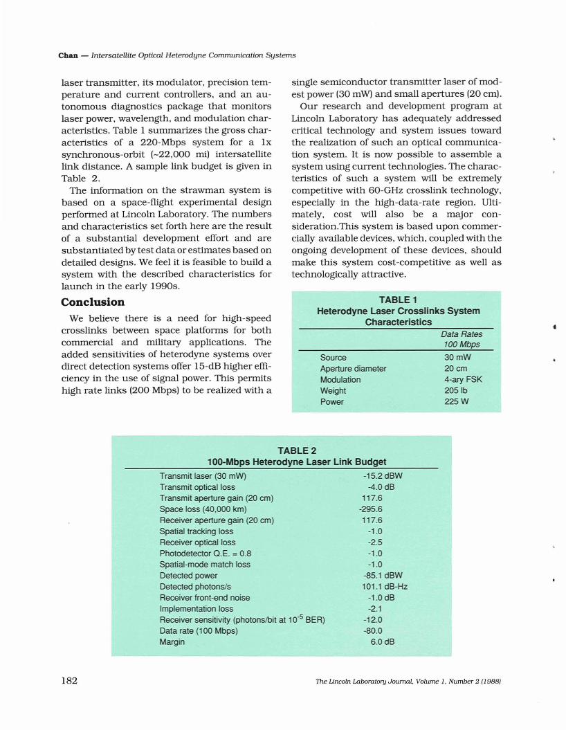
TABLE 1Heterodyne Laser Crosslinks System
Characteristics
single semiconductor transmitter laser of modest power (30 mW) and small apertures (20 em).
Our research and development program atLincoln Laboratory has adequately addressedcritical technology and system issues towardthe realization of such an optical communication system. It is now possible to assemble asystem using current technologies. The characteristics of such a system will be extremelycompetitive with 60-GHz crosslink technology,especially in the high-data-rate region. Ultimately, cost will also be a major consideration.This system is based upon commercially available devices, which, coupled with theongOing development of these devices, shouldmake this system cost-competitive as well astechnologically attractive.
laser transmitter, its modulator, precision temperature and current controllers, and an autonomous diagnostics package that monitorslaser power, wavelength, and modulation characteristics. Table 1 summarizes the gross characteristics of a 220-Mbps system for a Ixsynchronous-orbit (-22,000 mil intersatellitelink distance. A sample link budget is given inTable 2.
The information on the strawman system isbased on a space-flight experimental designperformed at Lincoln Laboratory. The numbersand characteristics set forth here are the resultof a substantial development effort and aresubstantiated by test data or estimates based ondetailed designs. We feel it is feasible to build asystem with the described characteristics forlaunch in the early 1990s.
ConclusionWe believe there is a need for high-speed
crosslinks between space platforms for bothcommercial and military applications. Theadded sensitivities of heterodyne systems overdirect detection systems offer 15-dB higher efficiency in the use of signal power. This permitshigh rate links (200 Mbps) to be realized with a
SourceAperture diameterModulationWeightPower
Data Rates100 Mbps
30mW20cm4-ary FSK2051b225W
•
TABLE 2100-Mbps Heterodyne Laser Link BUdget
Transmit laser (30 mW)Transmit optical lossTransmit aperture gain (20 cm)Space loss (40,000 km)Receiver aperture gain (20 cm)Spatial tracking lossReceiver optical lossPhotodetector a.E. = 0.8Spatial-mode match lossDetected powerDetected photonslsReceiver front-end noiseImplementation lossReceiver sensitivity (photons/bit at 10-5 BER)Data rate (100 Mbps)Margin
-15.2 dBW-4.0 dB
117.6-295.6117.6
-1.0-2.5-1.0-1.0
-85.1 dBW101.1 dB-Hz
-1.0 dB-2.1
-12.0-80.0
6.0dB
182 The Lincoln Laboratory JournaL Volume 1. Number 2 (1988)
Chan - Intersatellite Optical Heterodyne Communication Systems
AcknowledgementThe work described in this paper is an aggregateof the output of a large number of contributors. Though it is impossible to name eachindividually, the author wishes to acknowledgetheir contributions to a fine team effort.
References1. V.W.S. Chan, "Coherent Optical Space CommunicationsSystem Architecture and Technology Issues," Proc. SHE295, 10 (1981) and J. Lightwave Techno!. LT-5, 633 (1987).2. F.W. Floyd, "Space Data Relay Networks," Tech. Rep. TR572 (MIT/Lincoln Laboratory, Lexington, MA, 1981). DTIC#AD-B06I 650L.3. J.E. Kaufmann, "Phase and Frequency Tracking Considerations for Heterodyne Optical Communications," Proc.lTC/USA '82 (International Foundation for Telemetering,Woodland Hills, CA, 1982), pg 123.4. R.S. Bondurant, S.D. Lowney. and J.E. Kaufmann,"Frequency Tracking for Optical Heterodyne Communication Systems," Optical Society oj America, 1984 AnnualMeeting, San Diego, CA (Optical Society of America, 1984),paper TuW1.5. G.L. Abbas, S.B. Alexander, R.S. Bondurant, V.W.S.Chan, J.M. Elder, L.L. Jeromin, J.E. Kaufmann, S.D.Lowney. D.v.L. Marquis, F.G. Walther, D. Welford, andS.T.K. Yee, "Near Quantum-Limited Operation of a GaAlAsLaser Heterodyne Communication System: CLEO '85, Baltimore, MD, 21-24 May 1985 (Optical Society of America,1985), pg 52.6. S. Kobayashi, Y. Yamamoto, M. Ito, and T. Mimura,"Direct Frequency Modulation in AlGaAs Semiconductor
The Lincoln Laboratory Journal. Volume 1, Number 2 (19881
Lasers: IEEE J. Quantum Electron. QE-18, 582 (1982).7. D. Welford and S.B. Alexander, "100-Mbit/s 4-ary Frequency Shift Key Modulation of a GaAlAs SemiconductorDiode Laser: Digest OSAQ Conference on Lasers and Electrooptics, Washington, DC (Optical Society of America,1984), paper WK1.8. S.B. Alexander and D. Welford, "Equalization ofSemiconductor Diode Laser Frequency Modulation With a PassiveNetwork: Electron. Lett. 21, 361 (1985).9. D. Welford and S.B. Alexander, "GaAlAs SemiconductorDiode Laser 4-ary Frequency Shift Key Modulation at 100Mbit/s: Electron. Lett. 21, 12 (1985).10. H.P. Yuen and V.W.S. Chan, "Noise in Homodyne andHeterodyne Detection: Opt. Lett. 8, 177 (1983).11. D.F. Walls, "Squeezed States of Light: Nature 306, ]41(1983).]2. B.M. Oliver, "Signal to Noise Ratios in PhotoelectricMixing," Proc. IRE 49, 1960 (1961).13. G.L. Abbas, V.W.S. Chan, and T.K. Yee, "Noise inHomodyne and Heterodyne Detection," Opt. Lett. 8, 4]9(1983).14. G.L. Abbas, V.W.S. Chan, and T.K. Yee, "A DualDetector Optical Heterodyne Receiver for Local OscillatorNoise Suppression," J. Lightwave Techno!. LT-3, 1110(1985).15. S.B. Alexander, "Design of Wide-Band Optical Heterodyne Balanced Mixed Receivers: J. Lightwave Techno!. LT5, 523 (1987).16. G.L. Abbas and V.W.S. Chan, "Optimal Design andPerformance of a Dual-Detector Optical Heterodyne Receiver for Local Oscillator Noise Suppression: IEEE GlobalTelecomm. ConJ Rec. (IEEE, New York, 1983), pg 422.17. K.A. Winick and P. Kumar, "Spatial Model MatchingEfficiencies for Heterodyned GaAlAs Semiconductor Lasers: J. Lightwave Techno!. LT-6, 513 (1988).18. P. Van Hove and V.W.S. Chan, "Spatial AcquisitionAlgorithms and Systems for OpticalISL," IEEE Int. ConJ onCommun. (IEEE, New York, 1983), pg 1208.
183
Chan - Intersatellite Optical Heterodyne Communication Systems
Bibliography
G.L. Abbas and V.W.S. Chan, "Optical Design and Performance of a Dual-Detector Optical Heterodyne Receiver forLocal Oscillator Noise Suppression," IEEE Global Communication ConI, San Diego, CA, 28 November-l December1983, pg 422.G.L. Abbas, V.W.S. Chan, and T.K. Yee, "Cancellation ofLocal Oscillator Intensity Noise Caused by the RelaxationOscillation of GaAlAs Lasers with a Dual-Detector Heterodyne Receiver," Conf. on Optical Fiber Communication, NewOrleans, LA, 23-25 January 1984, pg 34.G.L. Abbas, V.W.S. Chan, and T.K. Yee, "A Dual-DetectorOptical Heterodyne Receiver for Local Oscillator NoiseSuppression," J. Lightwave Technol. LT-3, 1110 (1985).G.L. Abbas, J.G. Fujimoto, and V.W.S. Chan, "Far Field andSpectral Control of Laser Diode Arrays Using InjectionLocking," OFC '86. Atlanta, GA. 24-26 February 1986, pg40.G.L. Abbas, S. Yang, V.W.S. Chan, and J.G. Fujimoto,"Injection Behavior of High-Power Broad Area Diode Lasers," Opt. Lett. 12, 605 (1987).G.L. Abbas, S. Yang, J.G. Fujimoto, and V.W.S. Chan,"Injection Locking of High Power Broad Area Diode Lasers,"Postdeadline Papers oj the Optical Fiber CommunicationConf.. Reno, NV, 19-22 January 1987, pg 25.G.L. Abbas and T.K. Yee, "Power Dropout Statistics ofNearly-Single-Longitudinal-Mode Semiconductor Lasers,"IEEE J. Quantum Electron. QE-21, 1303 (1985).G.L. Abbas and T.K. Yee, "Power Dropout Statistics ofNearly-Single-Longi tudinal-Mode Semiconductor Lasers,"CLEO '84. Anaheim, CA. 19-22 June 1984, pg 212.S.B. Alexander, J. Bemays, RS. Bondurant, V.W.S. Chan,A.A. Colao, J.E. Kaufmann, E. Lee, A.N. Madiwale, P.F.Martin, A.D. Pillsbury, and E.A. Swanson, "An Opto-Mechanical Subsystem for Space-Based Coherent OpticalCommunication," to be published.S.B. Alexander, L.L. Jeromin, and S. Yang, "Demonstrationof Minimum Shift Keying for Frequency Modulation ofSemiconductor Lasers for 100 Mbps Coherent OpticalCommunication System." OFC '86. Atlanta, GA, 24-26February 1986, pg 50.S.B. Alexander and D. Welford, "GaAlAs SemiconductorDiode Laser 4-ary Frequency Shift Key Modulation at 100Mb/s," Electron. Lett. 21, 12 (1985).S.B. Alexander and D. Welford, "Magnitude and PhaseCharacteristics of Frequency Modulation in Directly Modulated GaAlAs Semiconductor Diode Lasers," J. LightwaveTechnol. LT-4, 1092 (1985).RS. Bondurant. "Response of Ideal Photodetectors toPhoton Flux and/or Energy Flux," Phys. Rev. A 32, 2797(1985).RS. Bondurant, S.D. Lowney, and J.E. Kaufmann, "Frequency Tracking for Optical Heterodyne CommunicationSystems," Optical Society oj American 1984 Meeting, SanDiego, CA. 29 October-2 November 1984, pg 33.RS. Bondurant, D. Welford, S.B. Alexander, and V.W.S.Chan, "Frequency Noise Cancellation in SemiconductorLasers by Non-Linear Heterodyne Detection," Opt. Lett. II,791 (1986).RS. Bondurant, D. Welford, S.B. Alexander, and V.W.S.Chan, "Frequency Noise Cancellation in SemiconductorLasers by Non-Linear Heterodyne Detection," Optical Society oj America Annual Meeting, Washington, DC, 14-18October 1985, pg 68.M.J. Carter, "Excess Jitter Accumulation in Optical Frequency Shift Keyed Heterodyne Regenerator Chains Due toNon-Negligible Laser Linewidth," OFC '86, Atlanta, GA,24-26 February 1986, pg 52.
184
V.W.S. Chan, "Phase-Noise-Cancelled Differential PhaseShift Keying for Coherent Communication with Noisy Lasers," IEEESymp. on lriformation Theory, Kobe, Japan, June1988.V.W.S. Chan, "Space Coherent Optical CommunicationsSystems - An Introduction," J. Lightwave Technol. LT-5,633 (1987).V.W.S. Chan, "Differential Frequency Modulation/Demodulation for Coherent Optical Communications," IEEESymp. on InJormation Theory, Brighton, England, 23-28June 1985.V.W.S. Chan, "Recent Results in Coherent Optical Communication," CLEO '84, Anaheim, CA, 19-22 June 1984, pg108; NSF Grantee-User Meeting on Optical Communication,San Diego, CA, 25-26 June 1984.V.W.S. Chan and L.L. Jeromin, "M-ary FSK Performance forCoherent Optical Communication Systems Using Semiconductor Lasers," IEEE Trans. Commun. COM-34 (1986).V.W.S. Chan, L.L. Jeromin, and J .E. Kaufman, "HeterodyneLASERCOM Systems Using GaAs Lasers for ISL Applications," ICC '83 Conf. Record, Vol. I, Boston, MA, 19-22 June1983, pg 1201.V. Jayaraman and V.W.S. Chan, "Polarization Tracking forOptical Heterodyne Communication," Optical Society ojAmerica Annual Meeting, Washington, DC, 14-18 October1985, pg 68.L.L. Jeromin and V.W.S. Chan, "Performance Estimates fora Coherent Optical Communication System," ConI onOptical Fiber Communication. New Orleans, LA, 23-25January 1984, pg 60.L.L. Jeromin and V.W.S. Chan, "Modulation Design for aHeterodyne Optical Communication System," IEEE GlobalCommunication ConI. Vol. I, San Diego, CA. 28 November-lDecember 1983, pg 412.L.L. Jeromin, B. Reiffen, and V.W.S. Chan, "Minimum ShiftKeying for Frequency Modulation of Semiconductor Lasers," OFC '85, San Diego, CA. 13-14 February 1985, pg 24.L.L. Jeromin and D. Welford, "The Effect of SpuriousIntensity Modulation in Semiconductor Diode Lasers on thePerformance of Optical Heterodyne, Frequency-ShiftKeyed, Communications Systems," J. Lightwave Technol.LT-4, 590 (1986).J.E. Kaufmann and V.W.S. Chan, "Coherent Optical Intersatellite Crosslinks," Symp. on Space Technological ChallengesJor the Future, United States Naval Academy, Annapolis, MD, 17-19 May 1988.J.E. Kaufmann and L.L. Jeromin, "Optical HeterodyneIntersatellite Links Using Semiconductor Lasers," IEEEGlobal Telecommunications ConI, 1984.S.D. Lowney and D.v.L. Marquis, "Frequency Acquisitionand Tracking for Optical Heterodyne CommunicationsSystems," J. Lightwave Technol. LT-5, 538 (1987).M. Lucente, G.M. Carter, and J.G. Fujimoto, "CarrierDynamics and Gain Nonlinearities in Broad Area DiodeLasers," International IEEE Semiconductor Conf., Boston,MA, 28 August-l September 1988.M. Lucente, G.M. Carter, and J.G. Fujimoto, "Phase Conjugate Four Wave Mixing in a Broad Area Diode Laser," CLEO'88, Anaheim, CA, 25-29 April 1988.M. Lucente, G.M. Carter, and J.G. Fujimoto, "NonlinearMixing and Phase Conjugation in Broad Area Diode Lasers,"IQEC '88. Tokyo, Japan, 18-22 July 1988.M. Lucente, J.G. FUjimoto,and G.M. Carter, "Four WaveMixing in a Broad Area Laser," Optical Fibers Communication Conf., New Orleans, LA, 25-28 January 1988.M.F. Richardson, "Optical Design for Laser Diode BasedCommunication Utilizing Heterodyne Detection," '85 SpringConf. on Applied Optics, Cherry Hill, NJ, 10-13 June 1985,pg 327.E.A. Swanson, G.L. Abbas, S. Yang, V.W.S. Chan, and J.G.
The Lincoln Laboratory Joumal. Volume 1. Number 2 (1988)
•
Chan - Intersatellite Optical Heterodyne Communication Systems
Fujimoto, "High-Speed Electronic Beam Steeling UsingInjection Locking of a Laser-Diode Array," Opt. Lett. 12,30(1987).E.A. Swanson, E. Arnau, and F.G. Walther, "MeasurementsofNatural Radiation Effects in a Low-Noise Avalanche PhotoDiode," IEEE Trans. Nucl. Sci. NS-34 (1987).E.A. Swanson and V.W.S. Chan, "Spatial Tracking Systemfor Heterodyne Optical Communication," MILCOM '84.Conference Record Vol. 2, Los Angeles, CA, 21-22 October1984, pg 17.4.K. Tamura, S.B. Alexander, and V.W.S. Chan, "PhaseNoise-Cancelled-Phase-Shift-Keying PNC-DPSK Modulation for Coherent Optical Communication Systems," OpticalFiberCommunicationsCorif.. New Orleans, LA, 25-28 January 1988.J.A. Taylor, A.D. Pillsbury, and M.F. Richardson, "DiodeLaser Transmitter for Space-Based Heterodyne Communication," to be published.F.G. Walther and D. Welford, "Dependence of Diode LaserLinewidth on Facet Reflectivity and Output Power," TopicalMeeting on Semiconductor Lasers, Albuquerque, NM, 10-11February 1987.D. Welford, "A Systems Approach to Facet ReflectivityOptimization of Laser Diodes for Optical Heterodyne Frequency-Shift-Keyed Communication Systems," OFC/IOOC'87, Reno, NY, 19-22 January 1987.D. Welford, "A Rate Equation Analysis for the FrequencyChirp to Modulated Power Ratio of a Semiconductor DiodeLaser," IEEE J. Quantum Electron. QE-21, 1749 (1985).K.A. Winick, "Atmospheric Turbulence Induced SignalFades on Optical Heterodyne Communication Links," IEEE
The Lincoln Laboratory Journal. Volume 1, Number 2 {19881
Global Telecommunications Corif. Record, Vol. 2. Atlanta,GA, 26-29 November 1986, pg 949.K.A. Winick, "Signal Fade Probability Distlibutions forOptical Heterodyne Receivers on Atmosphelically DistortedSatellite Links," IEEE Global Telecommunications ConJRecord, Vol. 2, 26-29 November 1984, pg 949.K.A. Winick and P. Kumar, "Spatial Model Matching Efficiencies for Heterodyned GaAlAs Semiconductor Lasers," J.Lightwave Technol. LT-6, 513 (1988).K.A. Winick and D.v.L. Marquis, "A Stellar ScintillationTechnique for the Measurement of Tilt Anisoplantism,"CLEO '88, Anaheim, CA, 2&-29 Aplil 1988.S. Yang, S.B. Alexander, J.G. Fujimoto, and V.W.S. Chan,"Injection Locking of a Diode Laser Array for CoherentHeterodyne Optical Communication," CLEO '87, Baltimore,MD, 27 Aplil-l May 1987.T.K. Yee, "Study of Intensity Noise of Nearly-Single-ModeSemiconductor Lasers Using Flow Graph Techniques,"Optical Society ofAmerica 1984 Meeting, San Diego, CA, 29October-2 November 1984, pg 94.T.K. Yee, V.W.S. Chan, and G.L. Abbas, "Intensity NoiseStatistics of GaAlAs Lasers," Optical Society of America/IEEE Sixth Topical Meeting on Optical Fiber Communication,New Orleans, LA, 28 February-2 March 1983, pg 70.T.K. Yee and D. Welford, "A Multimode Rate EquationAnalysis for Semiconductor Lasers Applied to Direct Intensity Modulation of Individual Longitudinal Modes," IEEE J.Quantum Electron. QE-22, 2116 (1986).T.K. Yee and D. Welford, ''Theoretical Study ofIntensity andCarlier Density Modulations in Semiconductor Lasers,"CLEO '85, Baltimore, MD, 21-24 May 1985, pg 74.
185
Chan - Intersatellite Optical Heterodyne Communication Systems
VINCENT W.S. CHAN wasborn in Hong Kong on November 5. 1948. He receivedBS. MS. EE. and PhD degrees in electrical engineering from MIT in 1971. 1971.1972. and 1974. respectively. in the area of opticalcommunication. From 1974
to 1977 he was an assistant professor with the School ofElectrical Engineering at Cornell University. teaching andconducting research in communication. He jOined LincolnLaboratory in 1977 and was Leader of the Optical Communication Technology Group between July 1983 and July1988. He is currently the Assistant Head of the Communication Division.
186 The Lincoln Laboratory Journal. Volume 1. Number 2 (1988)
•