Embed Size (px)
Citation preview

247
APM for a Constellation Intersatellite Link – EM Qualification and Lessons Learned
Frank Härtel* and Horst Kozilek*
Abstract For an Intersatellite Link (ISL) of a future constellation program, a study phase was initiated by ESA to design a mechanism for Radio Frequency communication. Airbus DS Friedrichshafen (ADSF) proposed a design based on the Antenna Pointing Mechanism (APM) family with modifications that met the stated needs of the constellation. A qualification program was started beginning in September 2015 to verify the launch and thermal loads and the equipment performance (Radio Frequency, Pointing, Microvibration and Magnetic Moment). Technical challenges identified with the Engineering Model will be discussed within this paper.
Introduction The heritage of ADSF for Antenna Pointing Mechanisms is more than twenty years, with a series of different pointing mechanisms. Those mechanisms were designed to deploy and point large dish antennas as well as small antenna horns for the X- and Ka-Band. Generally the requirements of such mechanisms include the velocity (<10 deg/sec), the lifetime (of more than 5 years), and the accuracy (<0.2 deg). These requirements are not too demanding, as the Antenna points towards the ground station and the satellite is in a low-Earth orbit. For the current constellation, these requirements are more demanding. As the Intersatellite Link shall establish the RF communication between two MEO satellites, a very fast pointing velocity is needed (> 60 deg/sec). A higher precision of <0.125 deg and an overall lifetime of 12 years are also required. These changes had a significant impact on the heritage design. The actuation chain had to be modified with larger motors and bearings. This led to an intensive redesign process with an increased mass. The impacts of these modifications have been verified within the qualification program, which will be presented, including results, within this paper.
Intersatellite Link Antenna Pointing Mechanism Background For a constellation program, RF Intersatellite Links between single satellites can support ranging and communication for uploading mission data or tele commands. These data shall be uploaded from one single ground station to the next reachable satellite and transmitted by the Intersatellite Link (see Figure 1) to further dedicated satellites. For this function each satellite has to be equipped with two Antenna Pointing Mechanisms for data transfer in the K-Band. To establish such a constant network, the APM has to be able to point in each vector direction of the hemisphere. Additionally the movement towards a new pointing destination has to be very quick in order to enlarge the time for the data link communication. ADSF has a substantial heritage in building APMs for communication to ground applications. ADSF follows the approach of elevation over azimuth axis pointing systems. These systems have proven their high reliability and robustness over a multitude of different missions and accumulated a time in orbit of more than 35 years. * Airbus Defence and Space, Friedrichshafen, Germany
Proceedings of the 43rd Aerospace Mechanisms Symposium, NASA Ames Research Center, May 4-6, 2016
https://ntrs.nasa.gov/search.jsp?R=20160008137 2018-06-04T16:38:25+00:00Z

248
Figure 1. Intersatellite Link – Principle
For constellation programs, the components’ cost have a higher impact than in nominal single satellite missions. A consequent design-to-cost approach was followed using open-loop stepper motors and as many standard off-the shelf elements as possible. In Figure 2 the different elements can be seen. An elevation over azimuth axes approach was used for the APM design. An indirect (using gear wheels) actuation principle was chosen to ameliorate the power (holding current reduction) and pointing (gear ratio) budget. The Azimuth axis is supported by a bearing in O-configuration. In the azimuth axis there is a slip ring installed, transferring the power and signals to the elevation stage. The RF signal is transferred using a waveguide and two rotary joints (one to the spacecraft and one to the elevation stage). On top of the azimuth stage a stiff supporting structure (Yoke) is installed, providing the interfaces for the Elevation Axis with its Antenna Supporting Bracket, the elevation actuation chain (comparable to Azimuth actuation chain), and the interface for the HRM. The HRM is locking all relative movements of the Azimuth and Elevation Stage by transferring the loads into the spacecraft structure.
Figure 2. Intersatellite Link Mechanism
Slip Ring
Elevation Rotary Joint
Base bracket
HRM
NEA
MLI
Antenna Inertia Dummy
Elev
atio
n St
age
Azi
mut
h St
age
Azimuth Stepper Motor
Waveguide
Elevation Rotary Joint
249
Compared to the heritage projects, the motor size had to be significantly increased in order to achieve the demanding velocities and motor torque margins according to ECSS. Besides this, the reference sensor of the azimuth axis had to be changed (2.7 million activations) from a mechanical precision switch to a Hall sensor switch. A demanding change was also the adaptation of the thermal management. As a constellation by nature has an orbit with a very high sun illumination and an orbit with almost no sun illumination; the variety of the thermal environment is more complex than for a sun-synchronous orbit. All described changes led to increased masses and therefore higher vibration loads. The Hold Down and Release Mechanism and the bearings had to be adapted in order to handle these increased vibration loads.
Qualification Approach
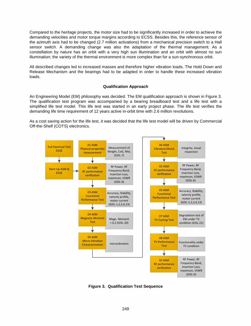
An Engineering Model (EM) philosophy was decided. The EM qualification approach is shown in Figure 3. The qualification test program was accompanied by a bearing breadboard test and a life test with a simplified life test model. This life test was started in an early project phase. The life test verifies the demanding life time requirement of 12 years active in-orbit time with 2.6 million revolutions. As a cost saving action for the life test, it was decided that the life test model will be driven by Commercial Off-the-Shelf (COTS) electronics.
Integrity, visual inspection
RF Power, RF Frequency Band,
Insertion Loss, maximum, VSWR
(GISL-6)
microvibration
Accuracy, Stability, velocity profile, motor current
(GISL-1,2,3,4,13)
Measurement of Weight, CoG, MoI,
(GISL-7)
Full Electrical TestEGSE
Start-Up ASM & EGSE
01 ASMPhysical properties
measurement
03 ASMFunctional
Performance Test
05 ASMMicro-Vibration Characterisation
02 ASMRF performance
verification
06 ASMVibration/Shock
Test
Degradation test of EM under TV
condition (GISL-21)
07 ASMTV-Cycling Test
RF Power, RF Frequency Band,
Insertion Loss, maximum, VSWR
(GISL-6)
02 ASMRF performance
verification
Functionality under TV condition
08 ASMTV Performance
Test
Accuracy, Stability, velocity profile, motor current
(GISL-1,2,3,4,13)
03 ASMFunctional
Performance Test
Magn. Moment < 0,2 (GISL-20)
04 ASMMagnetic Moment
Test
RF Power, RF Frequency Band,
Insertion Loss, maximum, VSWR
(GISL-6)
02 ASMRF performance
verification
Figure 3. Qualification Test Sequence

250
During the start-up of the APM with COTS electronics no significant anomalies (e.g., wrong cabling or communication error) were found. An overall mass of 10.8 kg (as designed) was verified during the physical measurements.
Testing
All testing was to be performed in the Friedrichshafen testing facility. Due to availability at the vibration test facility, it was decided to perform the vibration test at Airbus DS Ottobrunn. After a non-conformance report, the test was continued in Friedrichshafen. Bearing Characterization Breadboard Test As the chosen bearings were increased in diameter compared to the heritage design, a breadboard test was performed to measure the impact on torque with the required velocity and temperature inputs. A customizable (all different types bearings used for the APM can be installed) bearing breadboard test setup was developed and manufactured. The test setup provides the ability to compare the influence of different bearing types, lubrication, materials and combinations. Performing the bearing characterization test as a breadboard test supports monitoring the quality of the procured components and provides the input data for the torque margin and the bearing analysis.
Figure 4. Bearing Characterization Test Set-up in a TV chamber
ISL bearing characterization was performed at seven different velocity levels (1 rpm, 3 rpm, 17 rpm, 25 rpm, 35 rpm, 45 rpm and 100 rpm) and four different temperature levels (-40°C, 0°C, 25°C and 65°C). Each characterization was started with a run-in test, turning the bearing clockwise and counter-clockwise for several minutes. After the run-in, the different velocity levels were repeated multiple times, deriving multiple resistive torque measurements. Comparing the results of the measurements (see Figure 5), it can be concluded that the bearing performance was as expected in the torque margin analysis. The worst case torque assumed in the analysis was 75 N-mm and verified by a measurement of 72 N-mm (-40°C measurement). At a lower velocity level a higher, but still acceptable, deviation of 6 N-mm between analysis and measurement was found. An interesting phenomenon was the higher rate increase of the resistive torque for hot and fast conditions. This was not investigated further, but viscous effects could be a possible source of such a behavior.
Conductive heater/cooler
Bearing Setup
Actuator
Torque Sensor
TVAC chamber

251
Breadboard testing gives Airbus DS GmbH the confidence of having a sufficient torque margin and that the friction behavior of the preloaded bearing configuration is modelled correctly.
Figure 5. Results of the Bearing Characterization measurements
Life Test The initially planned life testing at the end of the qualification campaign was skipped in favor of a separate life test program with a simplified model running in parallel to the EM test campaign. The aim was to provide a life-tested mechanism at the end of the 1.5-year EM design and qualification phase. Cost savings for the life test were realized by performing the test with the azimuth stage only. This solution was selected as the loads for the azimuth bearings (environmentally and in-orbit) were considered to be the worst case. The azimuth motor and both gears have the higher number of revolution during in-orbit life. Prior to life testing, a proper environmental conditioning was essential for the credibility of the life test. This environmental conditioning consists of a vibration test and a thermal settling. The thermal settling in general is not a problem, and was performed directly before the start of the life test under the specified acceptance temperature level in a thermal vacuum chamber. A higher effort was the task to set up the proper vibration level of the Life Test Model. The applied load levels for the life test model vibration test were not known or they had a low confidence level. This was the case due to the reconfiguration of the elevation axis and due to the early stage of the development phase. This conflict leads to a very high effort in the estimation of the vibration test levels for the life test model. The goal was to load the single components as high as possible (identical to the EM), but not to damage the bearings. The decision was made to estimate the test levels for the center of gravity. With those test levels it was possible to predict the loading of the bearings and the actuator during the vibration test. Bearing loads were applied with an elevation stage dummy mass implemented in the test setup. Initial approach to leave the dummy mass unsupported at the Hold-Down and Release Mechanism (HRM) led to unacceptable high bearing loads. An additional support structure became necessary and was implemented in the test setup. Designing and implementing a support structure, different from the EM launch lock design, required much more effort than expected. The additional change of the initial motor location induced further changes of the life test set-up. Those changes consumed the schedule margin for life testing. During the performance of the accelerated life test, the time span of no motion (27 sec), due to communication, was removed. This was necessary to perform the 12-year in-orbit operation within about

252
7 months. Active cooling of the motor was necessary as the motor was continuously operating during the life time test without any interruption. Without cooling the motor would heat up too much.
Figure 6. ISL Life Test Model Vibration Test Setup
The life test motion set was derived from the current link budget analysis. The motion set of 25 positioning commands was to be repeated during the whole life time test while the environmental condition was changed. The life test also verifies the rotation capability of the motor bearings, the correct function of the planetary gear stage and the spur gear. According to ESSS no significant degradation during the required lifetime was allowed. Four main parameters were measured (Figure 7). The starting current with (blue) and without (green) detent torque, the resistance of all main and redundant windings (just one shown in red) and the slip ring resistance (yellow).
Figure 7. ISL Life Test Model Intermediate results for starting current, motor coil
and slip-ring resistance
012345678910
050
100150200250300350400
Res
ista
ncy
(Ohm
)
Conducted Cycles
Cur
rent
(mA)
Abs. Starting Current (mA) - Phase 1 main Abs. Starting Current (mA) - Phase 1 main clean
SR Resistancy (Ohm) SR 1 Winding Reistancy (Ohm) - main
Dummy Mass
Azimuth Stage Support structure

253
Having tested about 90% of the total life time (January 2016), it can be stated that all measured values indicate a full success of the life test. The starting motor current, slip ring resistance and motor coil resistance did not show any non-tolerable performance change. Performance Test Test setup for performance testing (see Figure 8) allows a stiff installation of two high-resolution absolute encoders to avoid additional measurement errors. The performance tests include measuring:
• pointing accuracy and stability • starting current measurements (with/without detent torque) • reference switch characteristic • power consumption of the motors under ambient conditions
Figure 8. ISL APM EM Performance Test Setup
Evaluation of the results showed that the test can be concluded successfully even under worst case ambient conditions with a maximum pointing error of about 0.08 deg. The maximum pointing error is shown in Figure 9 – left side (25 nominal positioning commands in a time span of 100 sec are plotted). The power consumption of a single motor is about 14 W per motor. Power consumption for one APM with two axes is estimated to be 28 W. Due to the long transmitting time in relation to the motion time an average power consumption of about 6 W is estimated.
Figure 9. ISL APM EM Performance exemplary Pointing & Power Test Results
2 4 6 8 10 12 14 16 18 20 22 24
-0.1
-0.05
0
0.05
0.1
Motion
Pos
ition
ing
Erro
r in
deg
Measurement 1Measurement 2Measurement 3Measurement 4Measurement 5Measurement 6
Mean Error Azimuth = 0.01308 degand STD = 0.0028098 deg
2 4 6 8 10 12 14 16 18 20 22 24 Motion
0.1 0.05 0 -0.05 -0.1
Pos
ition
ing
Erro
r in
deg
-50 -40 -30 -20 -10 0 10 20 30 400
1
2
3
4
5
6
7
8
Time in Sec
Pow
er in
Wat
t
Pow
er in
Wat
t
-50 -40 -30 -20 -10 0 10 20 30 40 50
8 7 6 5 4 3 2 1 0
Time in Sec
ISL APM Engineering Model
Azimuth Encoder
Elevation Encoder

254
RF Test The RF Link (Wave Guide with Rotary Joints) was a new development subsystem from MIRAD AG Switzerland. RF-performance measurement was done by a set of 24 static two-port measurements (changing azimuth and elevation pointing angle). An intermediate measurement can be seen in Figure 10.
Figure 10. ISL APM EM RF Test Setup
Evaluating the Return Loss (Figure 11 – left) and Insertion Loss (Figure 11 – right) over the full motion spectrum showed successful performance results. The return loss was below 1.2 dB and the insertion loss was below 0.8 dB. The angular variation of the Return Loss was slightly above the expected 0.1 dB.
Figure 11. ISL APM EM Return Loss (left) & insertion Loss (right) Test Results over the complete
motion range
All in all the performed work from MIRAD AG was fully in line with the required RF performance of the subsystem. Vibration Test The specification for the launch loads was given as 20G from 5 to 60 Hz and 6G from 60 to 100 Hz for the Sine Vibration and 0.12 g²/Hz x (M+20 kg)/(M + 1 kg) for Random Vibration. The Vibration Test was performed at Airbus DS in Ottobrunn and Friedrichshafen. The vibration was controlled via base force notching. The base force was directly measured by four force sensors installed underneath the mounting interface (see Figure 12). The base force limits are defined via the quasi static design loads. In order to protect the Azimuth main bearings and the Actuator from over testing, secondary notches were used. The
22 23 24 Frequency in GHz
-10 -20 -30 -40 -50 -60 -70
Ret
urn
Loss
Return Loss S22
22 23 24 X10 Frequency in GHz
-0.45
-0.5
-0.55
-0.6 -0.65
-0.7
-0.75
-0.8
-0.85
-0.9
Inse
rtion
Los
s in
dB
Insertion Loss S21
COTS EGSE
Port 1
Port 2
APM

255
bearings were limited to a peak Hertzian stress of 3360 MPa (including all ECSS ratings) and the Actuators were limited to 40 G acceleration at the center of gravity.
The X and Z axes could be qualified successfully with just minor usage of secondary notches. The Y axis was qualified to an input level of 5G. A load dependent behavior was found in intermediate testing (1/4 level limited to 10g response of the motor). The load dependent effect was investigated (see Figure 13). The ISL heritage design had to be adapted due to the more demanding requirements. The heritage HRM system did perfectly work for X and Z axis of the ISL, while enabling a frictionless release. In the Y axis, due to the design changes, too much load was transferred over the HRM Base interface. The enhancement of this interface, combined with some minor structural strengthening, will enable a qualification up to 20G load input.
Figure 12. ISL APM EM Vibration Test Setup
Figure 13. ISL APM EM Y- Axis Vibration Test (Acceleration on Elevation Motor)
As a series of subsequent qualification tests had to be done, the rework will be realized after the completion of the qualification test campaign. The residual risk for this rework and the final vibration qualification of the Y axis up to 20 G load input is limited. In summary, the EM vibration testing has proven its importance by identifying the need for the rework, while the equipment has nevertheless proven its viability for the usage in the constellation program.
Vibration Adapter
APM in locked configuration
Load cells for Base Force notching

256
^
Figure 14. ISL APM EM final Vibration Test Results – Transfer Function
(analysis in blue vs. test in pink) Thermal Vacuum Test The described non conformance for the vibration test delayed the Thermal Vacuum (TVAC) test. TVAC test is about to be started, results will be part of the AMS presentation. During the TVAC test, a non-operational cycle will be performed, followed by a set of seven operational cycles. During the seven operational cycles the EM will be driven with a standard pointing profile extracted from the global pointing budget. As the ISL will also be activated during transient phases in space, this test is of major importance to guarantee the functionality under extreme thermal conditions. At dedicated inspection points the starting current and the power consumption will be measured in hot and cold conditions. These measurements will also verify the bearing characterization breadboard tests.
Tem
pera
ture
Out
gass
ing
TV-C
ham
ber E
vacu
atio
n
>3h>1h
TV-C
ham
ber R
epre
ssur
izatio
n
+65°C
+23°C
-25°C
Perf
orm
ance
Tes
t>1h >1h >1h >1h>1h
Perf
orm
ance
Tes
t
Perf
orm
ance
Tes
t
+75°C
>1h
>3h-45°C
Perf
orm
ance
Tes
t
Perf
orm
ance
Tes
t
Perf
orm
ance
Tes
t
>1h >1h >1h >1h >1h
ISL
ASM
HRM
rele
ase
Perf
orm
ance
Tes
t
TV-C
ham
ber R
epre
ssur
izatio
n
TV-C
ham
ber E
vacu
atio
n
ISL
ASM
HRM
lock
ing >1h
>1h
Figure 15. ISL APM EM TVAC cycles
X-Axis Y-Axis
Z-Axis

257
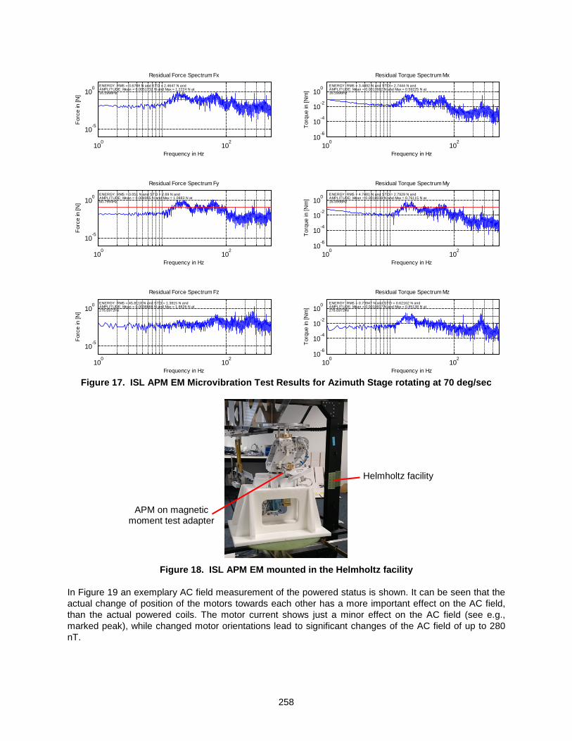
Microvibration Test The micro vibration test was successfully performed in the mechanisms group test facility. The test setup was developed and continuously improved during the last years (principle shown in Figure 16). The micro vibration test sensors logs the forces acting over a time period. This data is subsequently analyzed using a Fast Fourier Transformation algorithm to identify the frequencies and amplitudes of the emitted vibrations. Details regarding the analysis method can be found in [2].
Figure 16. ISL APM EM Microvibration Test Setup
Both axes were tested separately with different velocities from 10 deg/sec to 90 deg/sec. The test results for the rotation of the azimuth axis at 70 deg/sec can be seen in Figure 17. A second test method was to perform a motion profile with both axes operating in parallel. Test results evaluation showed that the required microvibration levels below 0.1 N and 0.1 N-m from 0-2000 Hz could not be met with the current stepper motors and motion profiles. Additionally, an impact from the COTS electronics was seen. Tests comparing a COTS electronics and the flight electronics showed an improvement by a factor of 2 for the flight electronics. Dedicated micro vibration reduction designs were developed at Airbus DS [3] in the past. Those design improvements can significantly reduce the microvibration. Further technical optimizations to reduce microvibration at spacecraft level are ongoing at Airbus DS GmbH. Magnetic Moment Test The Magnetic Moment Test is used to identify the influence of the magnetic components installed within the ISL APM EM on the satellite. Results of the EM can also be used to optimize the position of the APMs at spacecraft level. The two major sources of magnetic field emission are the stepper motors. In order to identify the field emission the ISL APM EM was installed in a Helmholtz Facility. Firstly, the remanent (non-powered) magnetic field emission was measured (360 measurements around the ISL APM EM). Secondly, the field was measured in powered condition (standard motion profile).
Amplifier
EGSE Control Laptop APM
XPC Data Acquisition
Kistler Table
Mechanical Isolation
Vibration Adapter
258
Figure 17. ISL APM EM Microvibration Test Results for Azimuth Stage rotating at 70 deg/sec
Figure 18. ISL APM EM mounted in the Helmholtz facility
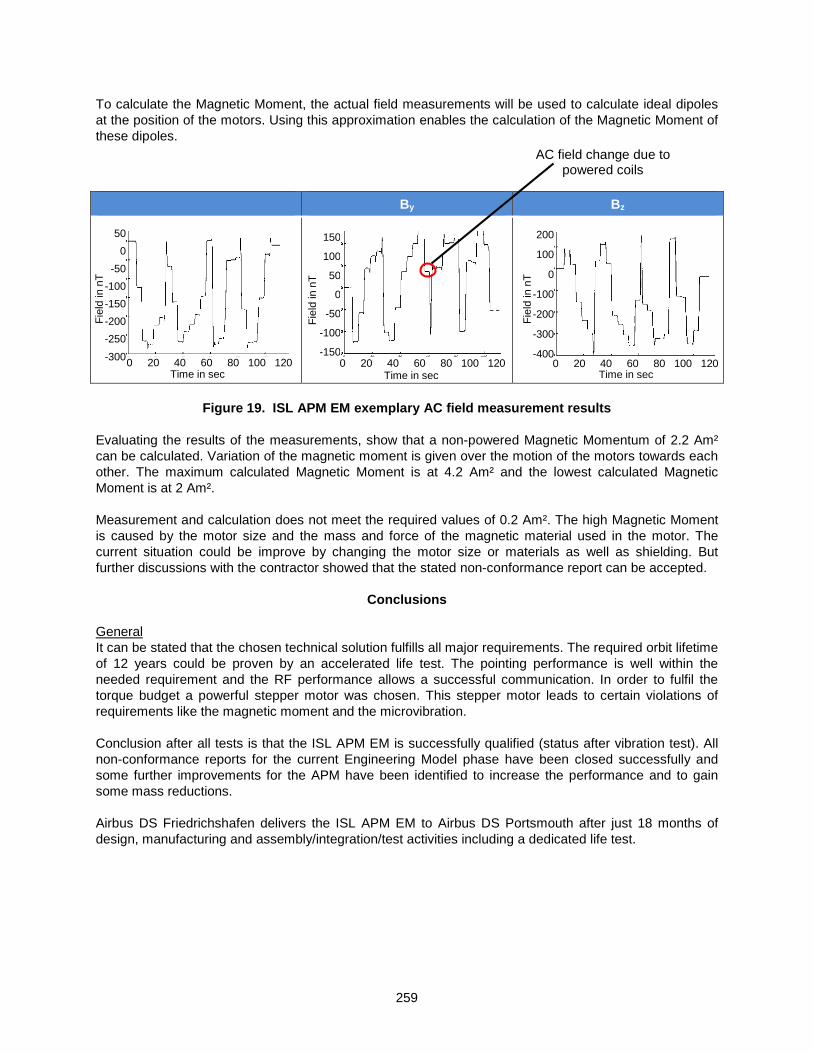
In Figure 19 an exemplary AC field measurement of the powered status is shown. It can be seen that the actual change of position of the motors towards each other has a more important effect on the AC field, than the actual powered coils. The motor current shows just a minor effect on the AC field (see e.g., marked peak), while changed motor orientations lead to significant changes of the AC field of up to 280 nT.
100
102
10-5
100
Forc
e in
[N]
Frequency in Hz
Residual Force Spectrum Fx
100
102
10-5
100
Forc
e in
[N]
Frequency in Hz
Residual Force Spectrum Fy
100
102
10-5
100
Forc
e in
[N]
Frequency in Hz
Residual Force Spectrum Fz
100
102
10-6
10-4
10-2
100
Torq
ue in
[Nm
]
Frequency in Hz
Residual Torque Spectrum Mx
100
102
10-6
10-4
10-2
100
Torq
ue in
[Nm
]
Frequency in Hz
Residual Torque Spectrum My
100
102
10-6
10-4
10-2
100
Torq
ue in
[Nm
]
Frequency in Hz
Residual Torque Spectrum Mz
ENERGY: RMS = 3.6708 N and STD = 2.4647 N andAMPLITUDE: Mean = 0.0051732 N and Max = 1.2224 N at16.5998Hz
ENERGY: RMS = 3.051 N and STD = 2.69 N andAMPLITUDE: Mean = 0.004955 N and Max = 1.0883 N at60.7994Hz
ENERGY: RMS = 45.8118 N and STD = 1.3815 N andAMPLITUDE: Mean = 0.0038868 N and Max = 1.8626 N at276.6972Hz
ENERGY: RMS = 3.4492 N and STD = 2.7444 N andAMPLITUDE: Mean = 0.0017662 N and Max = 0.59225 N at16.5998Hz
ENERGY: RMS = 4.7481 N and STD = 2.7929 N andAMPLITUDE: Mean = 0.0018038 N and Max = 0.76115 N at16.5998Hz
ENERGY: RMS = 0.73947 N and STD = 0.62162 N andAMPLITUDE: Mean = 0.0010917 N and Max = 0.85138 N at276.6972Hz
Helmholtz facility
APM on magnetic moment test adapter
259
Fiel
d in
nT
0 20 40 60 80 100 120
200
100
0
-100
-200
-300
-400
Time in sec
To calculate the Magnetic Moment, the actual field measurements will be used to calculate ideal dipoles at the position of the motors. Using this approximation enables the calculation of the Magnetic Moment of these dipoles.
By Bz
Figure 19. ISL APM EM exemplary AC field measurement results
Evaluating the results of the measurements, show that a non-powered Magnetic Momentum of 2.2 Am² can be calculated. Variation of the magnetic moment is given over the motion of the motors towards each other. The maximum calculated Magnetic Moment is at 4.2 Am² and the lowest calculated Magnetic Moment is at 2 Am². Measurement and calculation does not meet the required values of 0.2 Am². The high Magnetic Moment is caused by the motor size and the mass and force of the magnetic material used in the motor. The current situation could be improve by changing the motor size or materials as well as shielding. But further discussions with the contractor showed that the stated non-conformance report can be accepted.
Conclusions
General It can be stated that the chosen technical solution fulfills all major requirements. The required orbit lifetime of 12 years could be proven by an accelerated life test. The pointing performance is well within the needed requirement and the RF performance allows a successful communication. In order to fulfil the torque budget a powerful stepper motor was chosen. This stepper motor leads to certain violations of requirements like the magnetic moment and the microvibration. Conclusion after all tests is that the ISL APM EM is successfully qualified (status after vibration test). All non-conformance reports for the current Engineering Model phase have been closed successfully and some further improvements for the APM have been identified to increase the performance and to gain some mass reductions. Airbus DS Friedrichshafen delivers the ISL APM EM to Airbus DS Portsmouth after just 18 months of design, manufacturing and assembly/integration/test activities including a dedicated life test.
Fiel
d in
nT
0 20 40 60 80 100 120
50
0
-50
-100
-150
-200
-250
-300 Time in sec
Fiel
d in
nT
0 20 40 60 80 100 120
150
100
50
0
-50
-100
-150
Time in sec
AC field change due to powered coils
260
Lessons Learned For each qualification test the major lessons learned are: The Bearing Characterization Breadboard Test provided at an early project state a series of very important results (lubrication verification, correct torque budget inputs, possible bearing working profile). As a lesson learned, this test will be standardized within the mechanism department to be used for all upcoming projects, in order to improve the internal bearing lubrication and torque database. The adequate Life Test conditioning proved to be challenging when using a simplified Life Test Model. Therefore for further projects, if possible, the EM will be used instead of a simplified model. A lot of effort in the extra assessment and testing can be saved. The Performance Test showed that the chosen technical solution (stepper motor, backlash-free gear with a low medium gear ratio and a bearing in O-configuration) can provide the needed accuracy of 0.1 deg without any challenges. The RF Test demonstrated the possibility to reduce cost and time to integration by selecting a novel supplier. The RF performance was outstanding. This shall support an open supplier selection for the future. The Vibration Test qualified the X and Z axes for a load input of 20G. Y-axis was qualified up to for 5G load input, as the load dependent effects had to be investigated in detail. The vibration test also showed the high value of such EM testing in order to reveal design challenges, occurring due to changes from heritage design solution. Functional analysis within the mechanism development process, connecting function to design elements could also help for future projects. With the proposed and investigated minor structural improvements the APM has proven its viability for the usage in the constellation program. The lessons learned of the TVAC Test will be presented at the AMS conference. The Microvibration Test and the Magnetic Moment Test are demonstrating a conflict of requirements. On the one hand side a certain velocity and accuracy is demanded. On the other side the motor sizing leads to the violation of the microvibration and magnetic moment requirements. This conflict of goals has to be assessed with the contractor. If the violation of the two named requirements cannot be accepted a more complex motorization concept has to be chosen (e.g., closed-loop Brushless DC Motor).
Acknowledgment
The author thanks the co-authors and the whole Intersatellite Link Study team for the support and the shared effort. Special thanks to ESA for the funding of the Intersatellite Link Study.
References
1. Danilidis, C., Eben, K., Lindemann, U. "A functional analysis approach for product reengineering”,
Procedia Engineering 9 (2011), 270-280. 2. M. Vitelli, B. Specht, F. Boquet, A process to verify the microvibration and pointing stability
requirements for the Bepi Colombo mission, ESA International Workshop on Instrumentation for Planetary Mission. (2012)
3. Kozilek, H., Specht, B., Soon Yong, S., Gyu Lee, S. “Micro Vibration Improvement of a stepper actuated mechanism“, ESMATS 2013, September 2013