Embed Size (px)
Citation preview
Vulcan R SeriesInstallation Manual
ENGLISH
www.bandg.com

Preface
DisclaimerAs Navico is continuously improving this product, we retain theright to make changes to the product at any time which may not bereflected in this version of the manual. Please contact your nearestdistributor if you require any further assistance.
It is the owner’s sole responsibility to install and use the equipmentin a manner that will not cause accidents, personal injury orproperty damage. The user of this product is solely responsible forobserving safe boating practices.
NAVICO HOLDING AS AND ITS SUBSIDIARIES, BRANCHES ANDAFFILIATES DISCLAIM ALL LIABILITY FOR ANY USE OF THIS PRODUCTIN A WAY THAT MAY CAUSE ACCIDENTS, DAMAGE OR THAT MAYVIOLATE THE LAW.
Governing Language: This statement, any instruction manuals, userguides and other information relating to the product(Documentation) may be translated to, or has been translated from,another language (Translation). In the event of any conflict betweenany Translation of the Documentation, the English language versionof the Documentation will be the official version of theDocumentation.
This manual represents the product as at the time of printing.Navico Holding AS and its subsidiaries, branches and affiliatesreserve the right to make changes to specifications without notice.
CopyrightCopyright © 2017 Navico Holding AS.
WarrantyThe warranty card is supplied as a separate document.
In case of any queries, refer to the brand website of your unit orsystem: www.bandg.com.
Compliance statementsThis equipment complies with:
• CE under 2014/53/EU Directive
Preface | Vulcan R Series Installation Manual 3
• The requirements of level 2 devices of the Radio communications(Electromagnetic Compatibility) standard 2008
• Part 15 of the FCC Rules. Operation is subject to the followingtwo conditions: (1) this device may not cause harmfulinterference, and (2) this device must accept any interferencereceived, including interference that may cause undesiredoperation.
The relevant Declaration of conformity is available in the product'ssection at the following website: www.bandg.com.
Industry CanadaIC RSS-GEN, Sec 8.4 Warning StatementThis device complies with Industry Canada license-exempt RSSstandard(s). Operation is subject to the following two conditions: (1)this device may not cause interference, and (2) this device mustaccept any interference, including interference that may causeundesired operation of the device.
Le présent appareil est conforme aux CNR d’Industrie
Canada applicables aux appareils radio exempts de licence. L’exploitation est autorisée aux deux conditions suivantes: (1)l’appareil ne doit pas produire de brouillage, et (2) l’utilisateur del’appareil doit accepter tout brouillage radioélectrique subi, même sile brouillage est susceptible d’en compromettre le fonctionnement.
WarningThe user is cautioned that any changes or modifications notexpressly approved by the party responsible for compliance couldvoid the user’s authority to operate the equipment.
This equipment generates, uses and can radiate radio frequencyenergy and, if not installed and used in accordance with theinstructions, may cause harmful interference to radiocommunications. However, there is no guarantee that theinterference will not occur in a particular installation. If thisequipment does cause harmful interference to radio or televisionreception, which can be determined by turning the equipment offand on, the user is encouraged to try to correct the interference byone or more of the following measures:
• Reorient or relocate the receiving antenna
4 Preface | Vulcan R Series Installation Manual
• Increase the separation between the equipment and receiver• Connect the equipment into an outlet on a circuit different from
that of the receiver• Consult the dealer or an experienced technician for help
Internet usageSome features in this product use an internet connection toperform data downloads and uploads. Internet usage via aconnected mobile/cell phone internet connection or a pay-per-MBtype internet connection may require large data usage. Your serviceprovider may charge you based on the amount of data you transfer.If you are unsure, contact your service provider to confirm rates andrestrictions.
Countries of intended use in the EUAT - Austria
BE - Belgium
BG - Bulgaria
CY - Cyprus
CZ - Czech Republic
DK - Denmark
EE - Estonia
FI - Finland
FR - France
DE - Germany
GR - Greece
HU - Hungary
IS - Iceland
IE - Ireland
IT - Italy
LV - Latvia
LI - Liechtenstein
LT - Lithuania
LU - Luxembourg
MT - Malta
NL - Netherlands
Preface | Vulcan R Series Installation Manual 5
NO - Norway
PL - Poland
PT - Portugal
RO - Romania
SK - Slovak Republic
SI - Slovenia
ES - Spain
SE - Sweden
CH - Switzerland
TR - Turkey
UK - United Kingdom
TrademarksB&G® is a registered trademark of Navico Holding AS.
Navionics® is a registered trademark of Navionics, Inc.
NMEA® and NMEA 2000® are registered trademarks of the NationalMarine Electronics Association.
SiriusXM® is a registered trademark of Sirius XM Radio Inc.
Fishing Hot Spots® is a registered trademark of Fishing Hot Spots Inc.Copyright© 2012 Fishing Hot Spots.
FUSION-Link™ Marine Entertainment Standard™ is a registeredtrademark of FUSION Electronics Ltd.
C-MAP® is a registered trademark of C-MAP.
SD™ and microSD™ are trademarks or registered trademarks ofSD-3C, LLC in the United States, other countries or both.
Additional mapping data: Copyright© 2012 NSI, Inc.: Copyright©2012 by Richardson’s Maptech.
Bluetooth® is a registered trademark of Bluetooth SIG, Inc.
Navico product referencesThis manual refers to the following Navico products:
• Broadband Sounder™ (Broadband Sounder)• Broadband 3G™ (Broadband 3G Radar)• Broadband 4G™ (Broadband 4G Radar)• DownScan Imaging™ (DownScan)
6 Preface | Vulcan R Series Installation Manual
• DownScan Overlay™ (Overlay)• GoFree™ (GoFree)• INSIGHT GENESIS® (Insight Genesis)
About this manualThis manual is a reference guide for installing the Vulcan Seriesunits.
Important text that requires special attention from the reader isemphasized as follows:
Ú Note: Used to draw the reader’s attention to a comment orsome important information.
Warning: Used when it is necessary to warnpersonnel that they should proceed carefully toprevent risk of injury and/or damage to equipment/personnel.
Preface | Vulcan R Series Installation Manual 7

8 Preface | Vulcan R Series Installation Manual
Contents
11 Check the contents11 Parts included
13 Overview13 Front controls14 Rear connections15 Card reader
16 Installation16 Mounting location17 Bracket mounting20 Panel mounting20 Bezel fitment and removal21 Transducer installation
22 Wiring22 Guidelines23 Power connections24 Power Control connection27 External alarm27 Connecting control devices28 NMEA 2000 backbone30 CZone connection to NMEA 200031 Transducer connection31 Radar connector
33 Software Setup33 First time startup33 Time and Date33 Start line - vessel configuration34 Rotating mast compensation35 Data source selection36 Device list37 Network groups38 Diagnostics39 Damping39 Calibration39 External Alarm Setup
Contents | Vulcan R Series Installation Manual 9
39 Echosounder setup43 StructureScan43 Radar setup46 Autopilot setup46 Fuel setup50 CZone setup51 Wireless setup56 NMEA 2000 setup57 Mercury®57 Software updates and data backup
61 Accessories
63 Supported data63 NMEA 2000 compliant PGN List
66 Technical specifications66 All units
68 Dimensional drawings68 5" unit dimensional drawings68 7" unit dimensional drawings69 9" unit dimensional drawings69 12" unit dimensional drawings
10 Contents | Vulcan R Series Installation Manual
Check the contentsCheck the contents of the box for your unit.
Parts included
ENGLISH
Installation Manual
bandg.com
ENGLISH
Installation Manual
bandg.com
ENGLISH
Installation Manual
bandg.com
ENGLISH
Installation Manual
bandg.com
1 2 3
4 5 6 7
8A 8B 8C
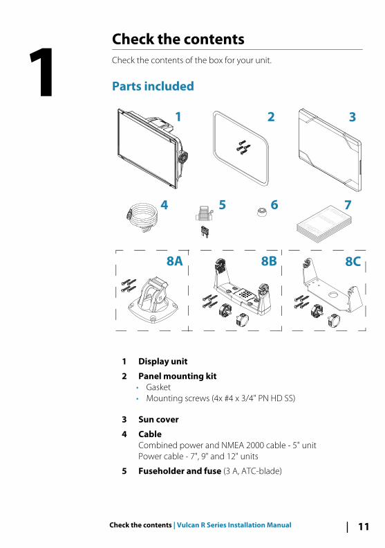
1 Display unit
2 Panel mounting kit• Gasket• Mounting screws (4x #4 x 3/4" PN HD SS)
3 Sun cover
4 CableCombined power and NMEA 2000 cable - 5" unitPower cable - 7", 9" and 12" units
5 Fuseholder and fuse (3 A, ATC-blade)
1
Check the contents | Vulcan R Series Installation Manual 11
6 Protective caps2x - 5" unit3x - 7", 9" and 12" units
7 Documentation package• Installation manual• Quick guide• Mounting template
8 A: Bracket mounting kit - 5" unit• Quick Release Bracket• Mounting screws (4x #10 x 3/4" PN HD SS)
B: Bracket mounting kit - 7" and 9" units• U bracket (plastic)• Mounting screws (4x #10 x 3/4" PN HD SS)• Bracket knobs (2x)
C: Bracket mounting kit - 12" unit• U bracket (metal)• Mounting screws (4x #10 x 3/4" PN HD SS)• Bracket knobs (2x)
12 Check the contents | Vulcan R Series Installation Manual
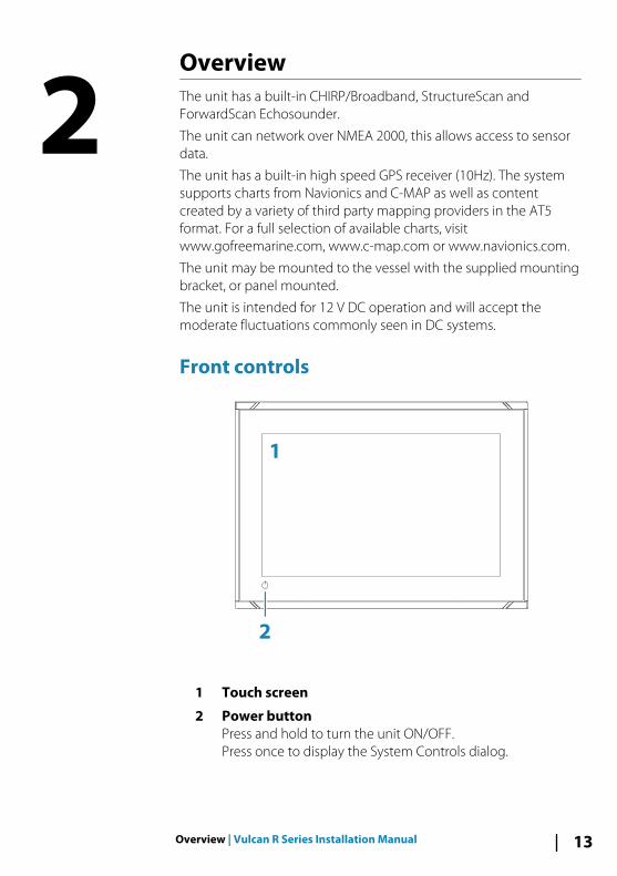
OverviewThe unit has a built-in CHIRP/Broadband, StructureScan andForwardScan Echosounder.
The unit can network over NMEA 2000, this allows access to sensordata.
The unit has a built-in high speed GPS receiver (10Hz). The systemsupports charts from Navionics and C-MAP as well as contentcreated by a variety of third party mapping providers in the AT5format. For a full selection of available charts, visitwww.gofreemarine.com, www.c-map.com or www.navionics.com.
The unit may be mounted to the vessel with the supplied mountingbracket, or panel mounted.
The unit is intended for 12 V DC operation and will accept themoderate fluctuations commonly seen in DC systems.
Front controls
2
1
1 Touch screen
2 Power buttonPress and hold to turn the unit ON/OFF.Press once to display the System Controls dialog.
2
Overview | Vulcan R Series Installation Manual 13
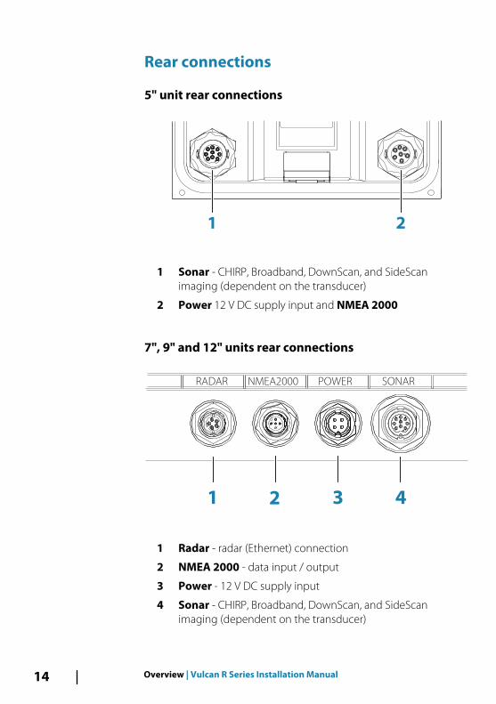
Rear connections
5" unit rear connections
1 2
1 Sonar - CHIRP, Broadband, DownScan, and SideScanimaging (dependent on the transducer)
2 Power 12 V DC supply input and NMEA 2000
7", 9" and 12" units rear connections
1 2 3 4
RADAR NMEA2000 POWER SONAR
1 Radar - radar (Ethernet) connection
2 NMEA 2000 - data input / output
3 Power - 12 V DC supply input
4 Sonar - CHIRP, Broadband, DownScan, and SideScanimaging (dependent on the transducer)
14 Overview | Vulcan R Series Installation Manual
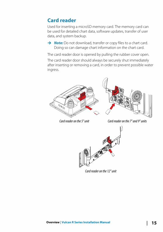
Card readerUsed for inserting a microSD memory card. The memory card canbe used for detailed chart data, software updates, transfer of userdata, and system backup.
Ú Note: Do not download, transfer or copy files to a chart card.Doing so can damage chart information on the chart card.
The card reader door is opened by pulling the rubber cover open.
The card reader door should always be securely shut immediatelyafter inserting or removing a card, in order to prevent possible wateringress.
Card reader on the 5" unit Card reader on the 7" and 9" units
Card reader on the 12" unit
Overview | Vulcan R Series Installation Manual 15
Installation
Mounting locationChoose the mounting locations carefully before you drill or cut.
For overall width and height requirements, refer to "Dimensionaldrawings" on page 68.
Do not mount any part where it can be used as a hand hold, whereit might be submerged, or where it will interfere with the operation,launching, or retrieving of the boat.
The unit should be mounted so that the operator can easily use thecontrols and clearly see the screen.
The unit has a high-contrast screen and is viewable in directsunlight, but for best results install the unit out of direct sunlight.The chosen location should have minimal glare from windows orbright objects.
The mounting location and surrounding materials may affect theinternal wireless and/or GPS performance. Metal and carbonmaterials are known to impact the performance in a negative way.Test the unit in its intended location to ensure satisfactoryreception.
An external GPS source can be added to overcome poor GPSreception areas.
An external wireless module can be added to compatible devices toovercome poor wireless reception areas.
Consider access to the card reader which is located in the back ofthe unit.
Check that it is possible to route cables to the intended mountinglocation.
Leave sufficient clearance to connect all relevant cables.
Before cutting a hole in a panel, make sure that there are no hiddenelectrical wires or other parts behind the panel.
Ensure that any holes cut are in a safe position and will not weakenthe boat’s structure. If in doubt, consult a qualified boat builder, ormarine electronics installer.
Ú Note: Where flush mounted, the enclosure should be dry andwell ventilated. In small enclosures, it may be required to fitforced cooling.
3
16 Installation | Vulcan R Series Installation Manual
Warning: Inadequate ventilation and subsequentoverheating of the unit may cause unreliable operationand reduced service life. Exposing the unit toconditions that exceeds the specifications couldinvalidate your warranty. – refer to "Technical specifications" onpage 66.
Bracket mounting
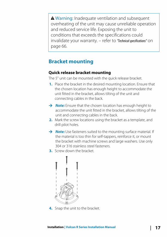
Quick release bracket mountingThe 5" unit can be mounted with the quick release bracket.
1. Place the bracket in the desired mounting location. Ensure thatthe chosen location has enough height to accommodate theunit fitted in the bracket, allows tilting of the unit andconnecting cables in the back.
Ú Note: Ensure that the chosen location has enough height toaccommodate the unit fitted in the bracket, allows tilting of theunit and connecting cables in the back.
2. Mark the screw locations using the bracket as a template, anddrill pilot holes.
Ú Note: Use fasteners suited to the mounting surface material. Ifthe material is too thin for self-tappers, reinforce it, or mountthe bracket with machine screws and large washers. Use only304 or 316 stainless steel fasteners.
3. Screw down the bracket.
4. Snap the unit to the bracket.
Installation | Vulcan R Series Installation Manual 17
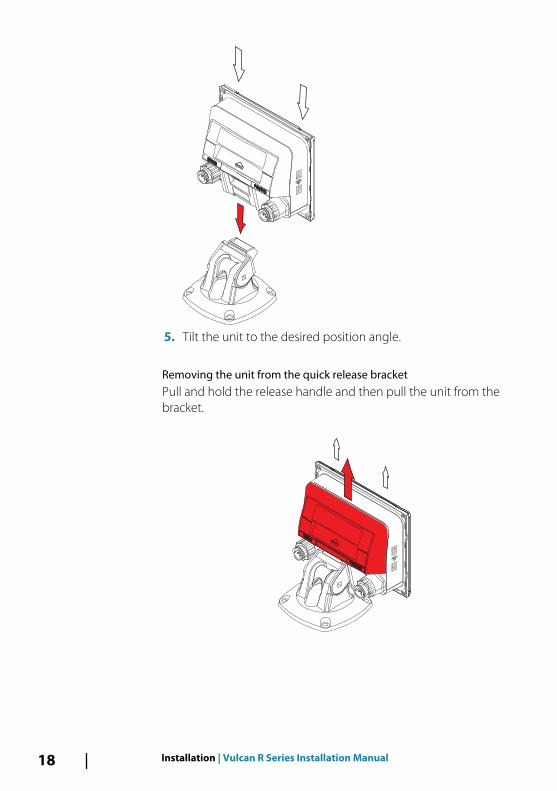
5. Tilt the unit to the desired position angle.
Removing the unit from the quick release bracketPull and hold the release handle and then pull the unit from thebracket.
18 Installation | Vulcan R Series Installation Manual
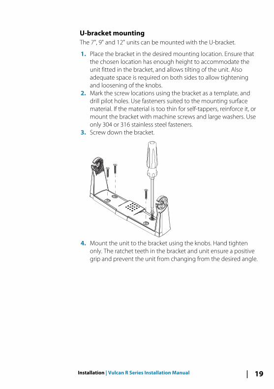
U-bracket mountingThe 7", 9" and 12" units can be mounted with the U-bracket.
1. Place the bracket in the desired mounting location. Ensure thatthe chosen location has enough height to accommodate theunit fitted in the bracket, and allows tilting of the unit. Alsoadequate space is required on both sides to allow tighteningand loosening of the knobs.
2. Mark the screw locations using the bracket as a template, anddrill pilot holes. Use fasteners suited to the mounting surfacematerial. If the material is too thin for self-tappers, reinforce it, ormount the bracket with machine screws and large washers. Useonly 304 or 316 stainless steel fasteners.
3. Screw down the bracket.
4. Mount the unit to the bracket using the knobs. Hand tightenonly. The ratchet teeth in the bracket and unit ensure a positivegrip and prevent the unit from changing from the desired angle.
Installation | Vulcan R Series Installation Manual 19
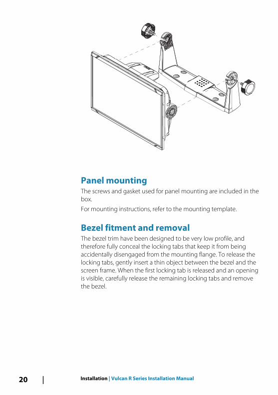
Panel mountingThe screws and gasket used for panel mounting are included in thebox.
For mounting instructions, refer to the mounting template.
Bezel fitment and removalThe bezel trim have been designed to be very low profile, andtherefore fully conceal the locking tabs that keep it from beingaccidentally disengaged from the mounting flange. To release thelocking tabs, gently insert a thin object between the bezel and thescreen frame. When the first locking tab is released and an openingis visible, carefully release the remaining locking tabs and removethe bezel.
20 Installation | Vulcan R Series Installation Manual
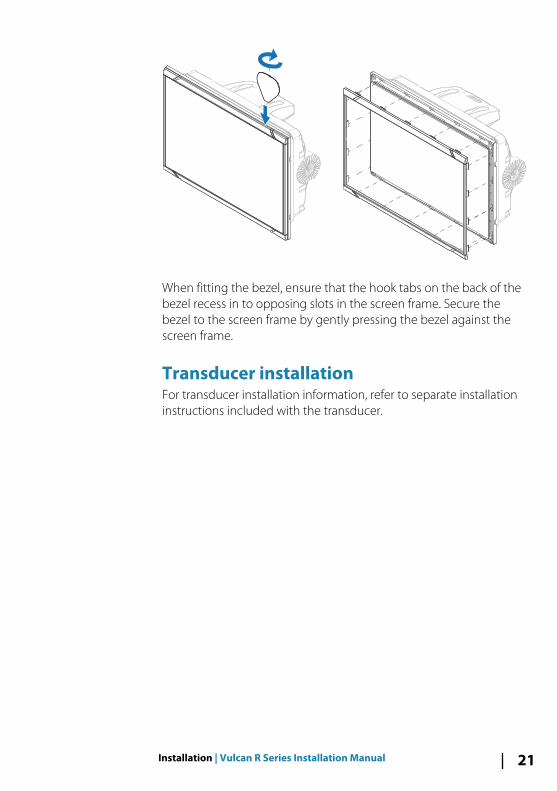
When fitting the bezel, ensure that the hook tabs on the back of thebezel recess in to opposing slots in the screen frame. Secure thebezel to the screen frame by gently pressing the bezel against thescreen frame.
Transducer installation For transducer installation information, refer to separate installationinstructions included with the transducer.
Installation | Vulcan R Series Installation Manual 21
Wiring
GuidelinesDon't:
• make sharp bends in the cables• run cables in a way that allows water to flow down into the
connectors• run the data cables adjacent to radar, transmitter, or large/high
current carrying cables or high frequency signal cables.• run cables so they interfere with mechanical systems• run cables over sharp edges or burrs
Do this:
• make drip and service loops• use cable-tie on all cables to keep them secure• solder/crimp and insulate all wiring connections if extending or
shortening the cables. Extending cables should be done withsuitable crimp connectors or solder and heat shrink. Keep joins ashigh as possible to minimize possibility of water immersion.
• leave room adjacent to connectors to ease plugging andunplugging of cables
Warning: Before starting the installation, be sure toturn electrical power off. If power is left on or turned onduring the installation, fire, electrical shock, or otherserious injury may occur. Be sure that the voltage of thepower supply is compatible with the unit.
Warning: The unit has a voltage rating of 12 V DC, itis not suited for use with 24 V DC systems.
Warning: The positive supply wire (red) shouldalways be connected to (+) DC with the supplied fuseor a circuit breaker (closest available to fuse rating).
4
22 Wiring | Vulcan R Series Installation Manual
Power connections
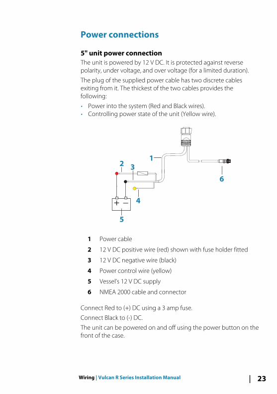
5" unit power connectionThe unit is powered by 12 V DC. It is protected against reversepolarity, under voltage, and over voltage (for a limited duration).
The plug of the supplied power cable has two discrete cablesexiting from it. The thickest of the two cables provides thefollowing:
• Power into the system (Red and Black wires).• Controlling power state of the unit (Yellow wire).
1
6
+ _
23
5
4
1 Power cable
2 12 V DC positive wire (red) shown with fuse holder fitted
3 12 V DC negative wire (black)
4 Power control wire (yellow)
5 Vessel’s 12 V DC supply
6 NMEA 2000 cable and connector
Connect Red to (+) DC using a 3 amp fuse.
Connect Black to (-) DC.
The unit can be powered on and off using the power button on thefront of the case.
Wiring | Vulcan R Series Installation Manual 23
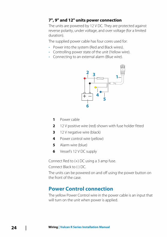
7", 9" and 12" units power connection The units are powered by 12 V DC. They are protected againstreverse polarity, under voltage, and over voltage (for a limitedduration).
The supplied power cable has four cores used for:
• Power into the system (Red and Black wires).• Controlling power state of the unit (Yellow wire).• Connecting to an external alarm (Blue wire).
+ _
1
23
5
6
4
1 Power cable
2 12 V positive wire (red) shown with fuse holder fitted
3 12 V negative wire (black)
4 Power control wire (yellow)
5 Alarm wire (blue)
6 Vessel’s 12 V DC supply
Connect Red to (+) DC using a 3 amp fuse.
Connect Black to (-) DC.
The units can be powered on and off using the power button onthe front of the case.
Power Control connectionThe yellow Power Control wire in the power cable is an input thatwill turn on the unit when power is applied.
24 Wiring | Vulcan R Series Installation Manual
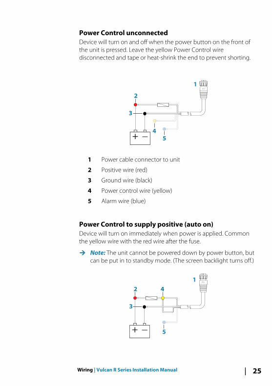
Power Control unconnectedDevice will turn on and off when the power button on the front ofthe unit is pressed. Leave the yellow Power Control wiredisconnected and tape or heat-shrink the end to prevent shorting.
+ _
1
2
5
4
3
1 Power cable connector to unit
2 Positive wire (red)
3 Ground wire (black)
4 Power control wire (yellow)
5 Alarm wire (blue)
Power Control to supply positive (auto on)Device will turn on immediately when power is applied. Commonthe yellow wire with the red wire after the fuse.
Ú Note: The unit cannot be powered down by power button, butcan be put in to standby mode. (The screen backlight turns off.)
+ _
1
2 4
3
5
Wiring | Vulcan R Series Installation Manual 25
1 Power cable connector to unit
2 Positive wire (red)
3 Ground wire (black)
4 Power control wire (yellow)
5 Alarm wire (blue)
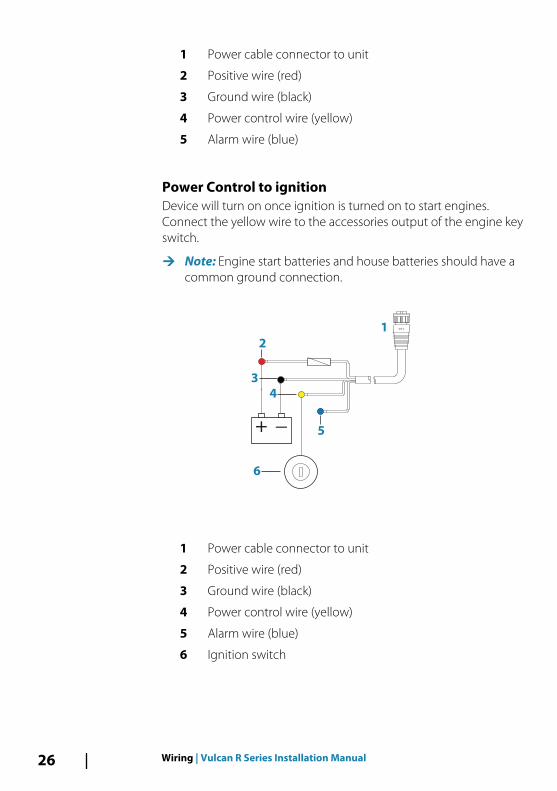
Power Control to ignitionDevice will turn on once ignition is turned on to start engines.Connect the yellow wire to the accessories output of the engine keyswitch.
Ú Note: Engine start batteries and house batteries should have acommon ground connection.
+ _ 5
1
2
3
4
6
1 Power cable connector to unit
2 Positive wire (red)
3 Ground wire (black)
4 Power control wire (yellow)
5 Alarm wire (blue)
6 Ignition switch
26 Wiring | Vulcan R Series Installation Manual
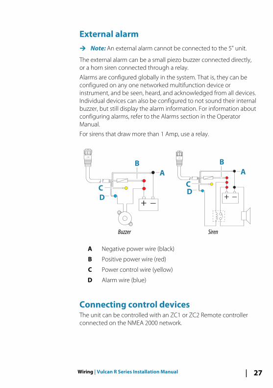
External alarmÚ Note: An external alarm cannot be connected to the 5" unit.
The external alarm can be a small piezo buzzer connected directly,or a horn siren connected through a relay.
Alarms are configured globally in the system. That is, they can beconfigured on any one networked multifunction device orinstrument, and be seen, heard, and acknowledged from all devices.Individual devices can also be configured to not sound their internalbuzzer, but still display the alarm information. For information aboutconfiguring alarms, refer to the Alarms section in the OperatorManual.
For sirens that draw more than 1 Amp, use a relay.
+ _
A
B
D
C
Buzzer
+ _
A
B
D
C
Siren
A Negative power wire (black)
B Positive power wire (red)
C Power control wire (yellow)
D Alarm wire (blue)
Connecting control devicesThe unit can be controlled with an ZC1 or ZC2 Remote controllerconnected on the NMEA 2000 network.
Wiring | Vulcan R Series Installation Manual 27
NMEA 2000 backbone
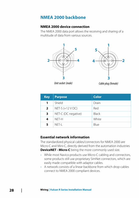
NMEA 2000 device connectionThe NMEA 2000 data port allows the receiving and sharing of amultitude of data from various sources.
2
1
3
4
5
Unit socket (male)
1
2
5
4
3
Cable plug (female)
Key Purpose Color
1 Shield Drain
2 NET-S (+12 V DC) Red
3 NET-C (DC negative) Black
4 NET-H White
5 NET-L Blue
Essential network informationThe standardized physical cables/connectors for NMEA 2000 areMicro-C and Mini-C, directly derived from the automation industriesDeviceNET - Micro-C being the more commonly used size.
• While most Navico products use Micro-C cabling and connectors,some products still use proprietary SimNet connectors, which areeasily made compatible with adaptor cables.
• A network consists of a linear backbone from which drop-cablesconnect to NMEA 2000 compliant devices.
28 Wiring | Vulcan R Series Installation Manual
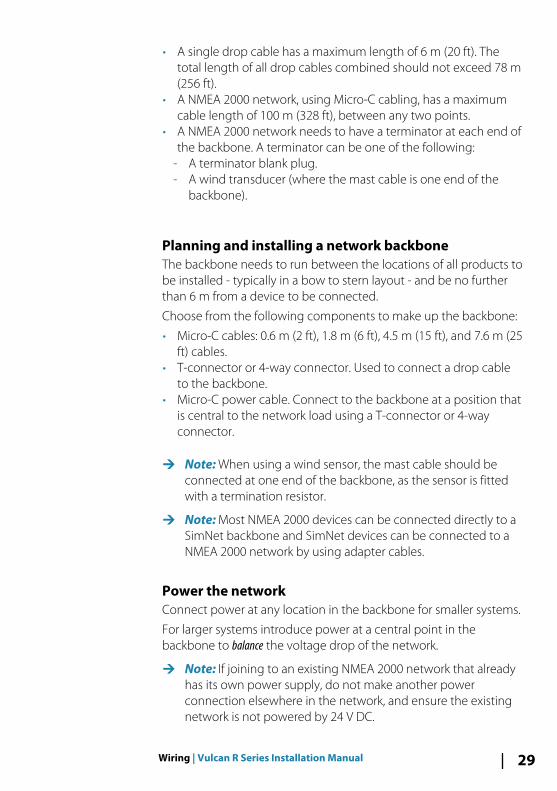
• A single drop cable has a maximum length of 6 m (20 ft). Thetotal length of all drop cables combined should not exceed 78 m(256 ft).
• A NMEA 2000 network, using Micro-C cabling, has a maximumcable length of 100 m (328 ft), between any two points.
• A NMEA 2000 network needs to have a terminator at each end ofthe backbone. A terminator can be one of the following:
- A terminator blank plug.- A wind transducer (where the mast cable is one end of the
backbone).
Planning and installing a network backboneThe backbone needs to run between the locations of all products tobe installed - typically in a bow to stern layout - and be no furtherthan 6 m from a device to be connected.
Choose from the following components to make up the backbone:
• Micro-C cables: 0.6 m (2 ft), 1.8 m (6 ft), 4.5 m (15 ft), and 7.6 m (25ft) cables.
• T-connector or 4-way connector. Used to connect a drop cableto the backbone.
• Micro-C power cable. Connect to the backbone at a position thatis central to the network load using a T-connector or 4-wayconnector.
Ú Note: When using a wind sensor, the mast cable should beconnected at one end of the backbone, as the sensor is fittedwith a termination resistor.
Ú Note: Most NMEA 2000 devices can be connected directly to aSimNet backbone and SimNet devices can be connected to aNMEA 2000 network by using adapter cables.
Power the networkConnect power at any location in the backbone for smaller systems.
For larger systems introduce power at a central point in thebackbone to balance the voltage drop of the network.
Ú Note: If joining to an existing NMEA 2000 network that alreadyhas its own power supply, do not make another powerconnection elsewhere in the network, and ensure the existingnetwork is not powered by 24 V DC.
Wiring | Vulcan R Series Installation Manual 29
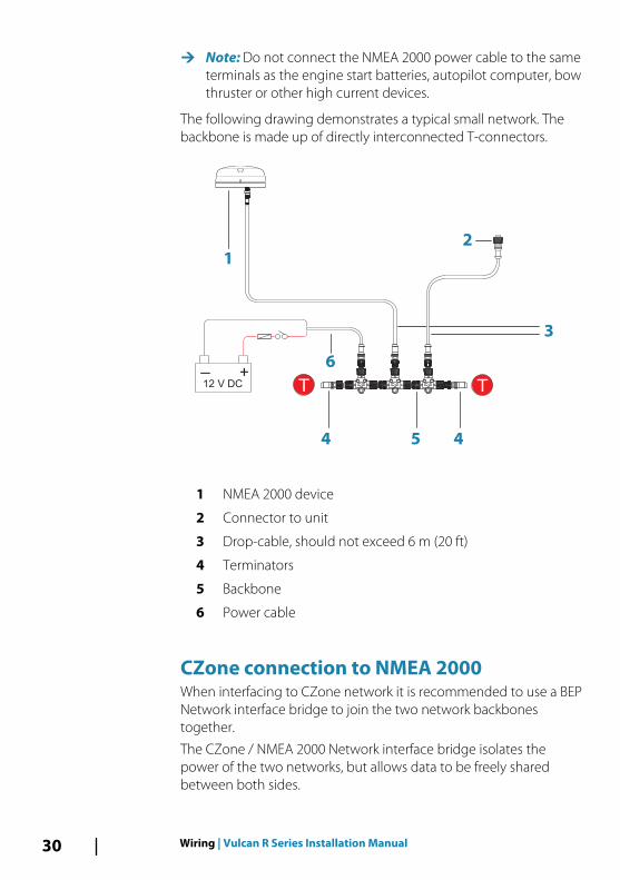
Ú Note: Do not connect the NMEA 2000 power cable to the sameterminals as the engine start batteries, autopilot computer, bowthruster or other high current devices.
The following drawing demonstrates a typical small network. Thebackbone is made up of directly interconnected T-connectors.
+_12 V DC T
3
44
6
2
1
T
5
1 NMEA 2000 device
2 Connector to unit
3 Drop-cable, should not exceed 6 m (20 ft)
4 Terminators
5 Backbone
6 Power cable
CZone connection to NMEA 2000When interfacing to CZone network it is recommended to use a BEPNetwork interface bridge to join the two network backbonestogether.
The CZone / NMEA 2000 Network interface bridge isolates thepower of the two networks, but allows data to be freely sharedbetween both sides.
30 Wiring | Vulcan R Series Installation Manual
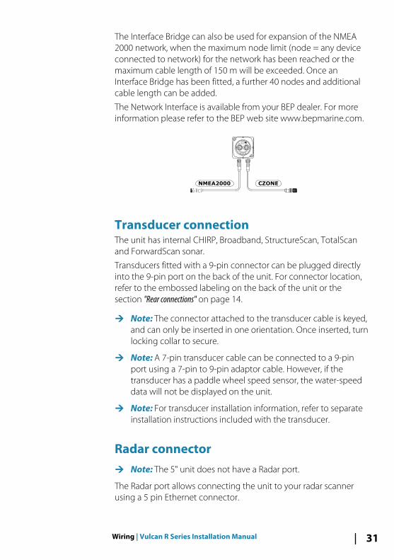
The Interface Bridge can also be used for expansion of the NMEA2000 network, when the maximum node limit (node = any deviceconnected to network) for the network has been reached or themaximum cable length of 150 m will be exceeded. Once anInterface Bridge has been fitted, a further 40 nodes and additionalcable length can be added.
The Network Interface is available from your BEP dealer. For moreinformation please refer to the BEP web site www.bepmarine.com.
NETWORK INTERFACE
Network 1 Network 2
CZONE
NETWORK
CZONENMEA2000
Transducer connectionThe unit has internal CHIRP, Broadband, StructureScan, TotalScanand ForwardScan sonar.
Transducers fitted with a 9-pin connector can be plugged directlyinto the 9-pin port on the back of the unit. For connector location,refer to the embossed labeling on the back of the unit or thesection "Rear connections" on page 14.
Ú Note: The connector attached to the transducer cable is keyed,and can only be inserted in one orientation. Once inserted, turnlocking collar to secure.
Ú Note: A 7-pin transducer cable can be connected to a 9-pinport using a 7-pin to 9-pin adaptor cable. However, if thetransducer has a paddle wheel speed sensor, the water-speeddata will not be displayed on the unit.
Ú Note: For transducer installation information, refer to separateinstallation instructions included with the transducer.
Radar connectorÚ Note: The 5" unit does not have a Radar port.
The Radar port allows connecting the unit to your radar scannerusing a 5 pin Ethernet connector.
Wiring | Vulcan R Series Installation Manual 31
1
2
3
4
5
Unit socket (female)
2
3
1
4
5
Cable plug (male)
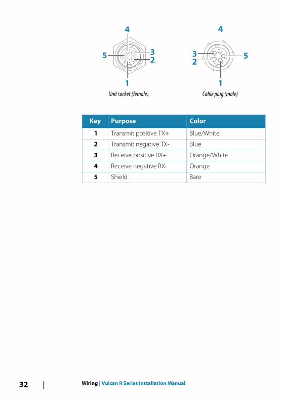
Key Purpose Color
1 Transmit positive TX+ Blue/White
2 Transmit negative TX- Blue
3 Receive positive RX+ Orange/White
4 Receive negative RX- Orange
5 Shield Bare
32 Wiring | Vulcan R Series Installation Manual
Software SetupThis unit requires some initial configuration before use, in order toget the most out of the product. The following sections focus onsettings that typically do not require change once configured. Userpreference settings and operation are covered in the OperatorManual.
Selecting the Home button opens the Home page, which has threedistinct areas. The scrollable left column of icons is the Tools panel.Select Settings in the Tools panel to open the Settings dialog andaccess items that require configuration.
First time startupWhen the unit is started for the first time, or after a factory default,the unit displays a setup wizard. Respond to the setup wizardprompts to select some fundamental setup options.
You can perform further setup using the system settings option andlater change settings made with the setup wizard.
Time and DateConfigure time settings to suit vessel location, along with time anddate formats.
Start line - vessel configurationIn order for the start line feature to work at it’s optimum, the exactposition of the vessels bow must be known. This is achieved byentering position offsets for the GPS sensor. These offsets combinedwith heading data will allow the software to accurately determinethe bows distance from the start line. To set the offsets, open theAdvanced Settings page and expand the Instruments option.
5
Software Setup | Vulcan R Series Installation Manual 33
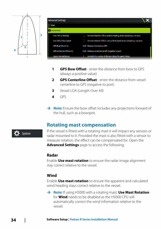
1 GPS Bow Offset - enter the distance from bow to GPS(always a positive value)
2 GPS Centerline Offset - enter the distance from vesselcenterline to GPS (negative to port)
3 Vessel LOA (Length Over All)
4 GPS
Ú Note: Ensure the bow offset includes any projections forward ofthe hull, such as a bowsprit.
Rotating mast compensationIf the vessel is fitted with a rotating mast it will impact any sensors orradar mounted to it. Provided the mast is also fitted with a sensor tomeasure rotation, the effect can be compensated for. Open theAdvanced Settings page to access the following;
RadarEnable Use mast rotation to ensure the radar image alignmentstay correct relative to the vessel.
WindEnable Use mast rotation to ensure the apparent and calculatedwind heading stays correct relative to the vessel.
Ú Note: If using H5000 with a rotating mast, Use Mast Rotationfor Wind needs to be disabled as the H5000 CPU willautomatically correct the wind information relative to thevessel.
2
1
4
3
34 Software Setup | Vulcan R Series Installation Manual
Data source selectionData sources provide live data to the system.
The data may originate from modules internal to the unit (forexample internal GPS or sonar), or external modules connected tothe NMEA 2000 or via NMEA 0183 if available on the unit.
When a device is connected to more than one source providing thesame data, the user can choose the preferred source. Beforecommencing with source selection make sure all external devicesand the NMEA 2000 backbone are connected and are turned on.
Auto SelectThe Auto Select option looks for all sources connected to thedevice. If more than one source is available for each data type,selection is made from an internal priority list. This option is suitablefor the majority of installations.
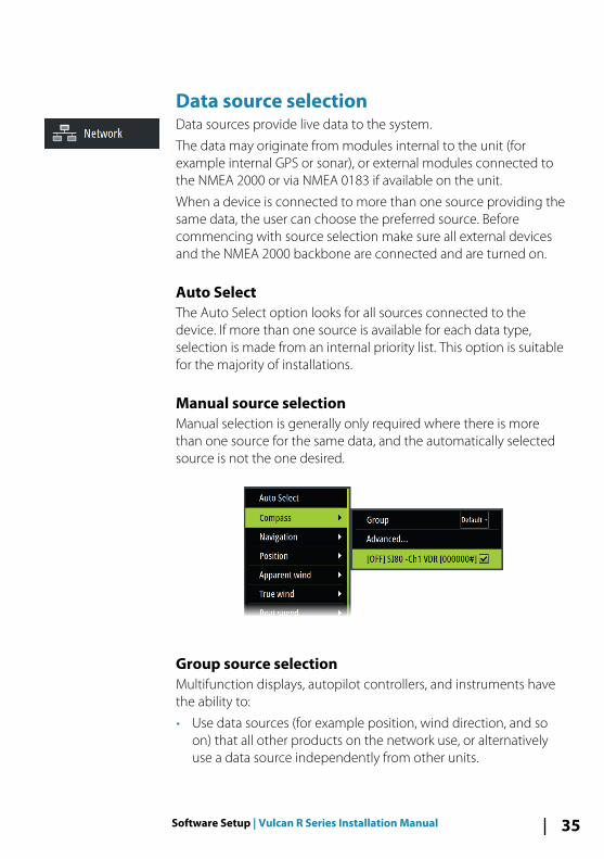
Manual source selectionManual selection is generally only required where there is morethan one source for the same data, and the automatically selectedsource is not the one desired.
Group source selectionMultifunction displays, autopilot controllers, and instruments havethe ability to:
• Use data sources (for example position, wind direction, and soon) that all other products on the network use, or alternativelyuse a data source independently from other units.
Software Setup | Vulcan R Series Installation Manual 35
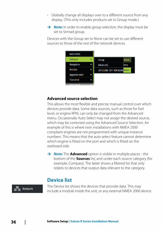
• Globally change all displays over to a different source from anydisplay. (This only includes products set to Group mode.)
Ú Note: In order to enable group selection, the display must beset to Simrad group.
Devices with the Group set to None can be set to use differentsources to those of the rest of the network devices.
Advanced source selectionThis allows the most flexible and precise manual control over whichdevices provide data. Some data sources, such as those for fuellevel, or engine RPM, can only be changed from the Advancedmenu. Occasionally Auto Select may not assign the desired source,which may be corrected using the Advanced Source Selection. Anexample of this is where twin installations with NMEA 2000compliant engines are not programmed with unique instancenumbers. This means that the auto select feature cannot determinewhich engine is fitted on the port and which is fitted on thestarboard side.
Ú Note: The Advanced option is visible in multiple places - thebottom of the Sources list, and under each source category (forexample, Compass). The latter shows a filtered list that onlyrelates to devices that output data relevant to the category.
Device list The Device list shows the devices that provide data. This mayinclude a module inside the unit, or any external NMEA 2000 device.
36 Software Setup | Vulcan R Series Installation Manual
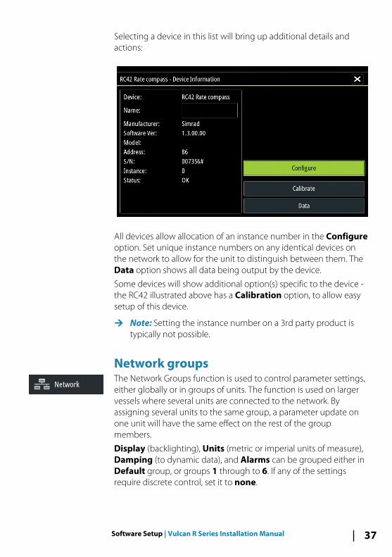
Selecting a device in this list will bring up additional details andactions:
All devices allow allocation of an instance number in the Configureoption. Set unique instance numbers on any identical devices onthe network to allow for the unit to distinguish between them. TheData option shows all data being output by the device.
Some devices will show additional option(s) specific to the device -the RC42 illustrated above has a Calibration option, to allow easysetup of this device.
Ú Note: Setting the instance number on a 3rd party product istypically not possible.
Network groupsThe Network Groups function is used to control parameter settings,either globally or in groups of units. The function is used on largervessels where several units are connected to the network. Byassigning several units to the same group, a parameter update onone unit will have the same effect on the rest of the groupmembers.
Display (backlighting), Units (metric or imperial units of measure),Damping (to dynamic data), and Alarms can be grouped either inDefault group, or groups 1 through to 6. If any of the settingsrequire discrete control, set it to none.
Software Setup | Vulcan R Series Installation Manual 37
DiagnosticsProvides information useful for identifying an issue with thenetwork.
Ú Note: The following information may not always indicate anissue that can be simply resolved with minor adjustment tonetwork layout or connected devices and their activity on thenetwork. However, Rx and Tx errors are most likely indicatingissues with the physical network, which may be resolved bycorrecting termination, reducing backbone or drop lengths, orreducing the number of network nodes (devices).
Bus stateSimply indicates whether the bus is powered, but not necessarilyconnected to any data sources. However, if bus shows as off, butpower is present along with an increasing error count, it is possiblethat termination or cable topology is incorrect.
Rx OverflowsThe unit received too many messages for its buffer before theapplication could read them.
Rx OverrunsThe unit contained too many messages for its buffer before thedriver could read them.
Rx/Tx ErrorsThese two numbers increase when there are error messages, anddecrease when messages are received successfully. These (unlikethe other values) are not a cumulative count. Under normaloperation these should be at 0. Values around 96 upwards indicatea heavily error prone network. If these numbers go too high for agiven device, it will automatically drop off the bus.
Fast Packet ErrorsCumulative counter of any fast packet error. This could be a missedframe, or a frame out of sequence etc. NMEA 2000 PGNs are madeof up to 32 frames. The entire message will be discarded when aframe is missed.
38 Software Setup | Vulcan R Series Installation Manual
Ú Note: Rx and Tx Errors often indicate an issue with the physicalnetwork, which may be resolved by correcting termination,reducing backbone or drop lengths, or reducing the number ofnetwork nodes (devices).
DampingIf data appears erratic or too sensitive, damping may be applied tomake the information appear more stable. With damping set to off,the data is presented in raw form with no damping applied.
CalibrationAn offset (positive or negative) can be applied to correctinaccuracies in boat speed, sea temp, air temp, barometric pressure,and depth sourced from NMEA 2000.
Ú Note: Any calibrations made here will ONLY be applied locallyto this unit. Other devices on the network will not have theseoffsets applied.
External Alarm SetupThe Siren Enabled option must be set in order for the unit toactivate the buzzer when an alarm condition arises. Its setting alsodetermines the operation of the external alarm output.
Echosounder setupMake general settings from the Echosounder Settings dialog. Defineand configure Echosounder sources in the Installation dialog.
Overlay downscanWhen a HDI transducer with DownScan is connected to yoursystem, you can overlay DownScan images on the regularEchosounder image.
When activated, the Echosounder menu expands to include basicDownScan options.
Structure depth offsetSetting for Structure transducers.
Software Setup | Vulcan R Series Installation Manual 39
All transducers measure water depth from the transducer to thebottom. As a result, water depth readings do not account for thedistance from the transducer to the lowest point of the boat in thewater or from the transducer to the water surface.
To show the depth from the lowest point of the boat to the bottom,do the following. Before setting the Structure offset, measure thedistance from the structure transducer to the lowest point of theboat in the water. If, for example, the distance is 0.3 m (1 ft), it will beinput as (minus) - 0.3 m (-1 ft).
To show the depth from the water surface to the bottom, do thefollowing. Before setting the Structure offset, measure the distancefrom the structure transducer to the water surface. If, for example,the distance is 0.3 m (1 ft), it will be input as (plus) 0.3 m (1 ft).
A setting of 0 (zero) causes the depth displayed to be the distancefrom the transducer to the bottom.
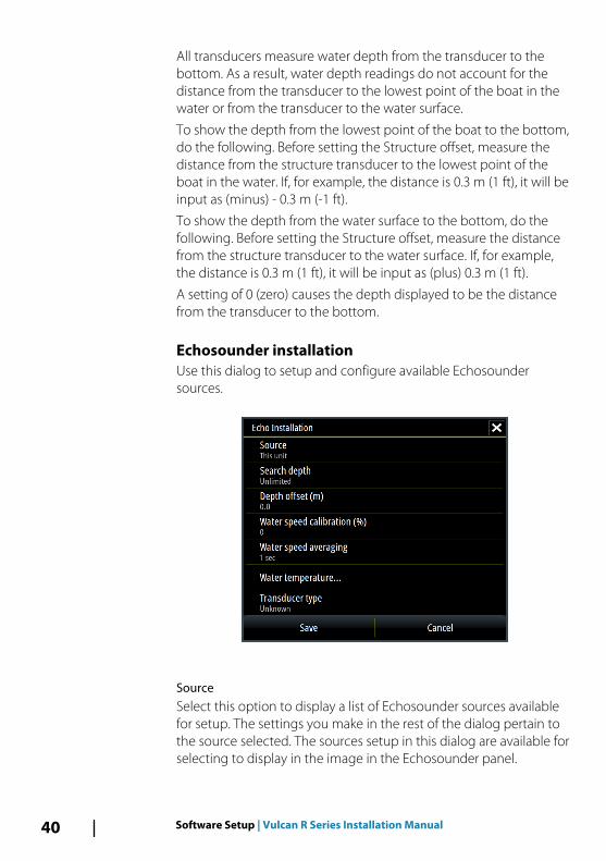
Echosounder installationUse this dialog to setup and configure available Echosoundersources.
SourceSelect this option to display a list of Echosounder sources availablefor setup. The settings you make in the rest of the dialog pertain tothe source selected. The sources setup in this dialog are available forselecting to display in the image in the Echosounder panel.
40 Software Setup | Vulcan R Series Installation Manual
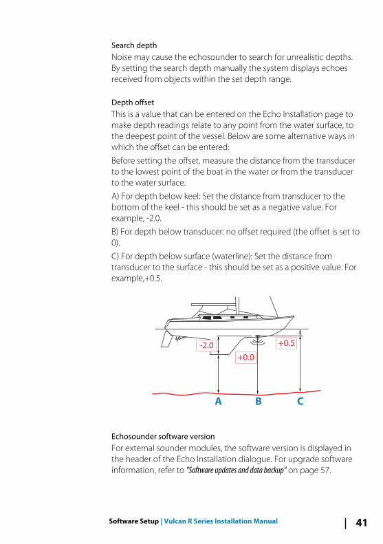
Search depthNoise may cause the echosounder to search for unrealistic depths.By setting the search depth manually the system displays echoesreceived from objects within the set depth range.
Depth offsetThis is a value that can be entered on the Echo Installation page tomake depth readings relate to any point from the water surface, tothe deepest point of the vessel. Below are some alternative ways inwhich the offset can be entered:
Before setting the offset, measure the distance from the transducerto the lowest point of the boat in the water or from the transducerto the water surface.
A) For depth below keel: Set the distance from transducer to thebottom of the keel - this should be set as a negative value. Forexample, -2.0.
B) For depth below transducer: no offset required (the offset is set to0).
C) For depth below surface (waterline): Set the distance fromtransducer to the surface - this should be set as a positive value. Forexample,+0.5.
A B C
+0.5
+0.0
-2.0
Echosounder software versionFor external sounder modules, the software version is displayed inthe header of the Echo Installation dialogue. For upgrade softwareinformation, refer to "Software updates and data backup" on page 57.
Software Setup | Vulcan R Series Installation Manual 41
Water speed calibrationWater speed calibration is used to adjust the speed value from thepaddle wheel to match the actual boat speed through the water.Actual speed can be determined from GPS speed over ground(SOG) or by timing the boat over a known distance. Water speedcalibration should be performed in calm conditions, with minimalwind and current movement.
Increase this value above 100 % if the paddle wheel is underreading, and decrease this value if it is over reading. For example, ifthe average water speed reads 8.5 knots (9.8 MPH) and SOG records10 knots (11.5 MPH) the calibration value needs to be increased to117 %. To calculate the adjustment, divide the SOG by thepaddlewheel speed, and multiply the product by 100.
Calibration range: 50-200 %. Default is 100 %.
Water speed averagingAverages water speed by measuring your speed at a selectedinterval of time. Water speed intervals range from one to thirtyseconds. For example if you select five seconds, your displayedwater speed will be based on averaging over 5 seconds of sampling.
Calibration range: 1-30 seconds. Default is 1 second.
Water temperature calibrationTemperature calibration is used to adjust the water temperaturevalue from the sonar transducer to match the data from anothertemperature sensor. It may be required to correct for localizedinfluences to the measured temperature.
Calibration range: -9.9° - +9.9°. Default is 0°.
Ú Note: Water temperature calibration only appears if thetransducer is temperature capable. Check transducer typeselection if this option should be available.
Transducer typeTransducer type is used for selecting the transducer modelconnected to the sonar module. The transducer selected willdetermine what frequencies the user can select during sonaroperation. In some transducers with built-in temperature sensors,the temperature reading may be inaccurate or not available at all ifthe wrong transducer is selected. Transducer temperature sensors
42 Software Setup | Vulcan R Series Installation Manual
are one of two impedances - 5k or 10k. Where both options aregiven for the same model transducer, refer to paperwork suppliedwith transducer to determine impedance.
ForwardScan installationAvailable when the ForwardScan feature is turned on. Forinstallation and setup information, refer to the separateForwardScan documentation.
StructureScanThis feature is automatically enabled when a TotalScan orStructureScan HD transducer is plugged in before the unit has beenpowered on.
It is possible to set a Structure depth offset for the structuretransducer. This setting is in the Echosounder Settings dialog.
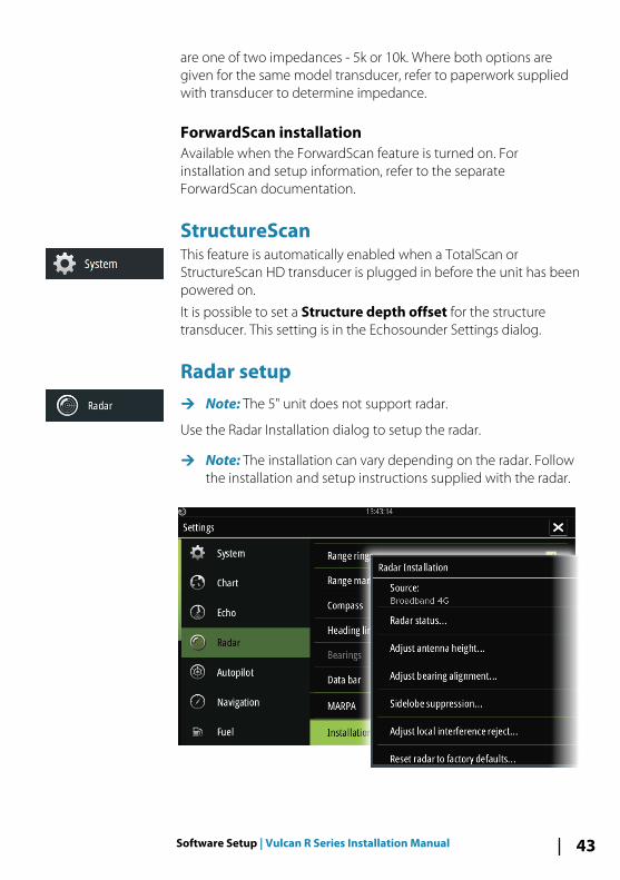
Radar setupÚ Note: The 5" unit does not support radar.
Use the Radar Installation dialog to setup the radar.
Ú Note: The installation can vary depending on the radar. Followthe installation and setup instructions supplied with the radar.
Software Setup | Vulcan R Series Installation Manual 43
Radar sourceIn a system with more than one radar, the correct device toconfigure can be selected from this menu.
Ú Note: Radars that support dual radar mode are representedtwice in the source list, with an A and B suffix.
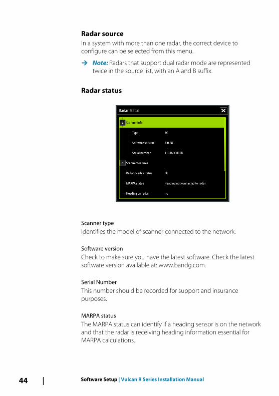
Radar status
Scanner typeIdentifies the model of scanner connected to the network.
Software versionCheck to make sure you have the latest software. Check the latestsoftware version available at: www.bandg.com.
Serial NumberThis number should be recorded for support and insurancepurposes.
MARPA statusThe MARPA status can identify if a heading sensor is on the networkand that the radar is receiving heading information essential forMARPA calculations.
44 Software Setup | Vulcan R Series Installation Manual
Reset device IDShould a radar be connected to the network that has beenconnected to a dual radar network in the past, it might not bedetected by the system because it might have an invalid Device ID.With the radar connected and powered up, select the Reset DeviceID button to resolve this problem.
Ú Note: This procedure must be performed with only one radaron the network, and only applies where a network combines anolder MFD with other MFDs.
Adjust antenna heightSet the radar scanner height relative to the water surface. The Radaruses this value to calculate the correct STC settings.
Adjust bearing alignmentThis is to align the heading marker on the screen with the centerline of the vessel. This will compensate for any slight misalignmentof the scanner during installation. Any inaccuracy will be evidentwhen using MARPA or chart overlay.
Point the boat to be perpendicular to the very end of a breakwateror peninsula. Adjust the bearing alignment setting, so that theheading marker and land mass intersect.
Sidelobe suppressionOccasionally false target returns can occur adjacent to strong targetreturns such as large ships or container ports. This occurs becausenot all of the transmitted radar energy can be focused into a singlebeam by the radar antenna, a small amount energy is transmitted inother directions. This energy is referred to as sidelobe energy andoccurs in all radar systems. The returns caused by sidelobes tend toappear as arcs.
Ú Note: This control should only be adjusted by experiencedradar users. Target loss in harbor environments may occur if thiscontrol is not adjusted correctly.
When the radar is mounted where there are metallic objects nearthe radar, sidelobe energy increases because the beam focus isdegraded. The increased sidelobe returns can be eliminated usingthe Sidelobe Suppression control.
Software Setup | Vulcan R Series Installation Manual 45
By default, this control is set to Auto and normally should not needto be adjusted. However, if there is significant metallic clutteraround the radar, sidelobe suppression may need to be increased.The control should be adjusted as follows:
1. Set Radar range to between 1/2 nm to 1 nm and SidelobeSuppression to Auto
2. Take the vessel to a location where sidelobe returns are likely tobe seen. Typically, this would be near a large ship, containerport, or metal bridge.
3. Traverse the area until the strongest sidelobe returns are seen.4. Change Auto sidelobe suppression to OFF then select and
adjust the sidelobe suppression control until the sidelobereturns are just eliminated. You may need to monitor 5-10 radarsweeps to be sure they have been eliminated.
5. Traverse the area again and readjust if sidelobes returns stilloccur.
6. Exit the dialog.
Adjust local interference rejectInterference from some onboard sources can interfere with theBroadband radar. One symptom of this could be a large target onthe screen that remains in the same relative bearing even if thevessel changes direction.
Choose from Local interference rejection LOW, MED or HIGH.Default is LOW.
Restore radar to factory defaultsThis option can be used to revert all user adjustments.
Autopilot setup For setup and commissioning of autopilot computers, refer to thedocumentation included with your autopilot system or autopilotcomputer.
Fuel setupThe fuel utility monitors a vessel's fuel consumption. Thisinformation is totaled to indicate trip and seasonal fuel usage, and isused to calculate fuel economy for display on instrument pages andthe data bar.
46 Software Setup | Vulcan R Series Installation Manual
To use the utility, a Navico Fuel Flow sensor, or a NMEA 2000 engineadaptor cable/gateway with Navico Fuel Data Storage device mustbe fitted to the vessel. Neither the Navico Fuel Flow sensor, nor theSuzuki engine interface require the use of a separate Fuel Storagedevice. Refer to the engine manufacturer or dealer for informationon whether or not your engine provides a data output, and whatadaptor is available to connect to NMEA 2000.
Once the physical connection is made, ensure source selection iscompleted. Multiple engine installations using Fuel Flow sensors, orFuel Data Storage devices, require setup of related engine locationin the Device list. For general source selection information, refer to"Data source selection" on page 35.
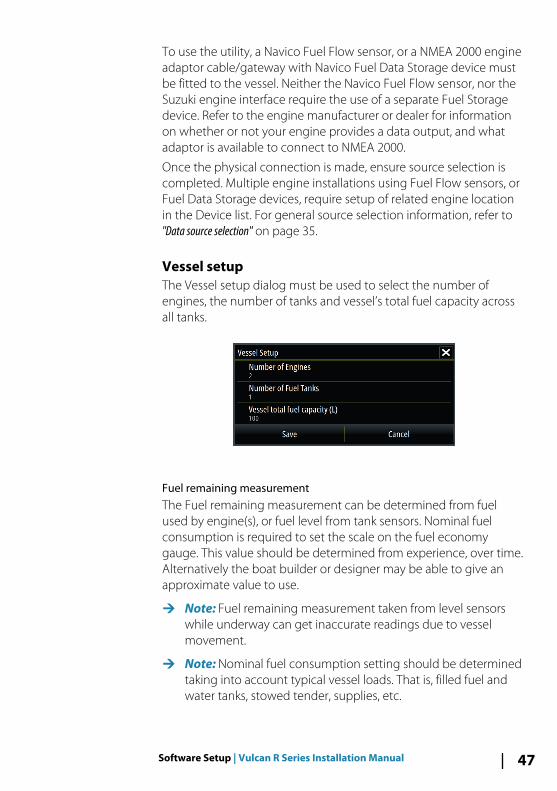
Vessel setupThe Vessel setup dialog must be used to select the number ofengines, the number of tanks and vessel’s total fuel capacity acrossall tanks.
Fuel remaining measurementThe Fuel remaining measurement can be determined from fuelused by engine(s), or fuel level from tank sensors. Nominal fuelconsumption is required to set the scale on the fuel economygauge. This value should be determined from experience, over time.Alternatively the boat builder or designer may be able to give anapproximate value to use.
Ú Note: Fuel remaining measurement taken from level sensorswhile underway can get inaccurate readings due to vesselmovement.
Ú Note: Nominal fuel consumption setting should be determinedtaking into account typical vessel loads. That is, filled fuel andwater tanks, stowed tender, supplies, etc.
Software Setup | Vulcan R Series Installation Manual 47
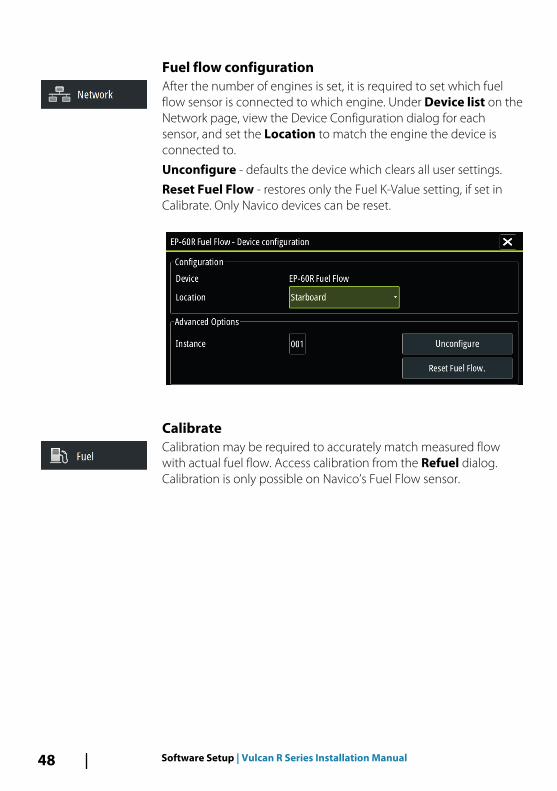
Fuel flow configurationAfter the number of engines is set, it is required to set which fuelflow sensor is connected to which engine. Under Device list on theNetwork page, view the Device Configuration dialog for eachsensor, and set the Location to match the engine the device isconnected to.
Unconfigure - defaults the device which clears all user settings.
Reset Fuel Flow - restores only the Fuel K-Value setting, if set inCalibrate. Only Navico devices can be reset.
CalibrateCalibration may be required to accurately match measured flowwith actual fuel flow. Access calibration from the Refuel dialog.Calibration is only possible on Navico’s Fuel Flow sensor.
48 Software Setup | Vulcan R Series Installation Manual
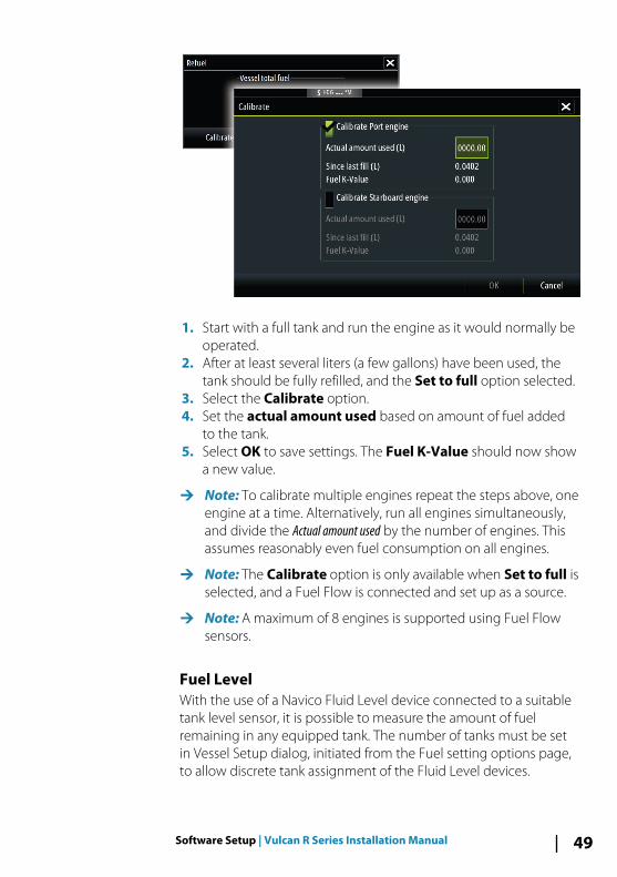
1. Start with a full tank and run the engine as it would normally beoperated.
2. After at least several liters (a few gallons) have been used, thetank should be fully refilled, and the Set to full option selected.
3. Select the Calibrate option.4. Set the actual amount used based on amount of fuel added
to the tank.5. Select OK to save settings. The Fuel K-Value should now show
a new value.
Ú Note: To calibrate multiple engines repeat the steps above, oneengine at a time. Alternatively, run all engines simultaneously,and divide the Actual amount used by the number of engines. Thisassumes reasonably even fuel consumption on all engines.
Ú Note: The Calibrate option is only available when Set to full isselected, and a Fuel Flow is connected and set up as a source.
Ú Note: A maximum of 8 engines is supported using Fuel Flowsensors.
Fuel LevelWith the use of a Navico Fluid Level device connected to a suitabletank level sensor, it is possible to measure the amount of fuelremaining in any equipped tank. The number of tanks must be setin Vessel Setup dialog, initiated from the Fuel setting options page,to allow discrete tank assignment of the Fluid Level devices.
Software Setup | Vulcan R Series Installation Manual 49
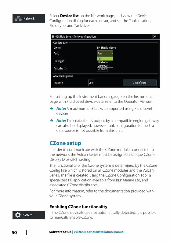
Select Device list on the Network page, and view the DeviceConfiguration dialog for each sensor, and set the Tank location,Fluid type, and Tank size.
For setting up the Instrument bar or a gauge on the Instrumentpage with Fluid Level device data, refer to the Operator Manual.
Ú Note: A maximum of 5 tanks is supported using Fluid Leveldevices.
Ú Note: Tank data that is output by a compatible engine gatewaycan also be displayed, however tank configuration for such adata source is not possible from this unit.
CZone setupIn order to communicate with the CZone modules connected tothe network, the Vulcan Series must be assigned a unique CZoneDisplay Dipswitch setting.
The functionality of the CZone system is determined by the CZoneConfig File which is stored on all CZone modules and the VulcanSeries. The file is created using the CZone Configuration Tool, aspecialized PC application available from BEP Marine Ltd, andassociated CZone distributors.
For more information, refer to the documentation provided withyour CZone system.
Enabling CZone functionalityIf the CZone device(s) are not automatically detected, it is possibleto manually enable CZone.
50 Software Setup | Vulcan R Series Installation Manual
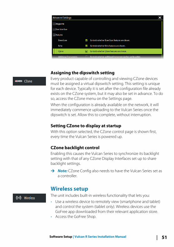
Assigning the dipswitch settingEvery product capable of controlling and viewing CZone devicesmust be assigned a virtual dipswitch setting. This setting is uniquefor each device. Typically it is set after the configuration file alreadyexists on the CZone system, but it may also be set in advance. To doso, access the CZone menu on the Settings page.
When the configuration is already available on the network, it willimmediately commence uploading to the Vulcan Series once thedipswitch is set. Allow this to complete, without interruption.
Setting CZone to display at startupWith this option selected, the CZone control page is shown first,every time the Vulcan Series is powered up.
CZone backlight controlEnabling this causes the Vulcan Series to synchronize its backlightsetting with that of any CZone Display Interfaces set up to sharebacklight settings.
Ú Note: CZone Config also needs to have the Vulcan Series set asa controller.
Wireless setupThe unit includes built-in wireless functionality that lets you:
• Use a wireless device to remotely view (smartphone and tablet)and control the system (tablet only). Wireless devices use theGoFree app downloaded from their relevant application store.
• Access the GoFree Shop.
Software Setup | Vulcan R Series Installation Manual 51
• Upload your logs to create custom maps at Insight Genesis.• Download software updates• Connect to third party applications
Connecting a tabletInstall the GoFree App on the tablet before following thisprocedure.
1. Set the internal wireless to Access Point mode. To do this,select the Wireless devices page in the Wireless settingsdialog and then select the Internal wireless. Next, select theMode option and then select Internal Access Point.
2. Select the Internal Wireless device on the Wireless devicespage to view its Network key.
3. Navigate to the wireless network connection page on the tablet,and find the unit or GoFree wireless xxxx network. If more thanone is in range, review the Wireless devices page on the unitto confirm which wireless device is connected to the unit.
4. Enter the Network Key in the tablet to connect to the network.5. Open the GoFree application - the unit should be automatically
detected. The name displayed will be either the default, or thatassigned in the Device Name setting. If the unit does notappear, follow the on screen instructions to manually find thedevice.
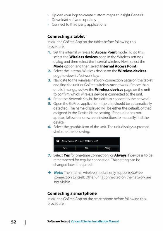
6. Select the graphic icon of the unit. The unit displays a promptsimilar to the following:
7. Select Yes for one-time connection, or Always if device is to beremembered for regular connection. This setting can bechanged later if required.
Ú Note: The internal wireless module only supports GoFreeconnection to itself. Other units connected on the network arenot visible.
Connecting a smartphoneInstall the GoFree App on the smartphone before following thisprocedure.
52 Software Setup | Vulcan R Series Installation Manual
1. Set the internal wireless to Access Point mode. To do this,select the Wireless devices page in the Wireless settingsdialog and then select the unit's Internal Wireless. Next, selectthe Mode option and then select Internal Access Point.
2. Select the Internal Wireless device on the Wireless devicespage to view its Network Key.
3. Navigate to the wireless network connection page on thesmartphone, and find the unit or GoFree wireless xxxx network. Ifmore than one is in range, review the Wireless devices pagefrom the unit's Wireless settings dialog to confirm whichwireless device is connected to the unit.
4. Enter the Network Key in the smartphone to connect to thenetwork.
5. Open the GoFree application on the smartphone, the unitshould be automatically detected. The name displayed will beeither the default, or that assigned in the Device Name setting. Ifthe unit does not appear, follow the on screen instructions tomanually find the device.
The MFD's display is shown on the smartphone. To change theMFD's display on the smartphone, use the MFD to change thedisplay on the MFD. The display change on the MFD is reflected onthe smartphone.
Remote controllersWhen a wireless device is connected, it should appear in theRemote controllers list.
Selecting Always allow means the device can automaticallyconnect without needing a password each time. This menu alsoallows disconnection of devices that no longer require access.
Wireless devicesThis dialog shows the internal wireless and any connected WIFI-1devices, as well as their IP and channel number. Selecting theinternal wireless or a WIFI-1 device provides additional detail.
Ú Note: WIFI-1 is possible with the 7", 9" and 12" unit only, usingthe Radar/Ethernet connection on the back of the unit.
To view and change internal wireless detail values (Network name(SSID), Network key, or Channel) the internal wireless must be inAccess Point (Internal Wifi) mode. To select a network (hotspot) toconnect to, the internal wireless must be in Client Mode.
Software Setup | Vulcan R Series Installation Manual 53
ModeDisplays if the internal wireless is set to Access Point (Internal Wifi)mode or Client Mode. Select it to change the wireless betweenAccess Point mode and Client Mode.
If the internal wireless is set to Access Point (Internal Wifi) mode,smartphones and tablets can access the unit to view and control(tablet only) it. Also when set to Access Point (Internal Wifi) modeyou can view and change the internal wireless details. Client Modeallows the unit internet access via a wireless hotspot.
HardwareProvides MAC address details of the wireless.
NetworksOnly visible if the internal wireless is in Client Mode when thedevice is selected. Shows a list of all networks (hotspots) availablefor connection. Select the name of the desired network to enter itsnetwork key and connect to it.
Network Name (SSID) Displays the name of the internal wireless network.
Only visible if the internal wireless is set to Access Point (InternalWifi) mode when the device is selected. You can select it andchange the internal wireless network to any name you want for easyidentification.
Network Key Required by the smartphone or tablet to connect to the internalwireless network.
Only visible if the internal wireless is set to Access Point (InternalWifi) mode when the device is selected. You can select it andchange it to increase network security. The key must be at least 8characters.
ChannelOnly visible if the internal wireless is set to Access Point (InternalWifi) mode when the device is selected. Select it to change theChannel setting to overcome potential interference to the internalwireless by another RF device transmitting in the same frequencyband.
54 Software Setup | Vulcan R Series Installation Manual
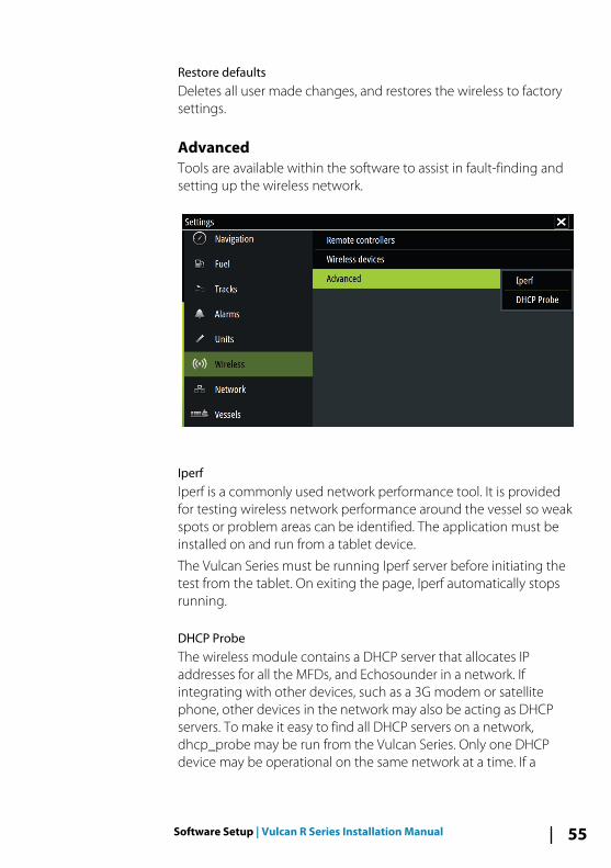
Restore defaultsDeletes all user made changes, and restores the wireless to factorysettings.
AdvancedTools are available within the software to assist in fault-finding andsetting up the wireless network.
IperfIperf is a commonly used network performance tool. It is providedfor testing wireless network performance around the vessel so weakspots or problem areas can be identified. The application must beinstalled on and run from a tablet device.
The Vulcan Series must be running Iperf server before initiating thetest from the tablet. On exiting the page, Iperf automatically stopsrunning.
DHCP ProbeThe wireless module contains a DHCP server that allocates IPaddresses for all the MFDs, and Echosounder in a network. Ifintegrating with other devices, such as a 3G modem or satellitephone, other devices in the network may also be acting as DHCPservers. To make it easy to find all DHCP servers on a network,dhcp_probe may be run from the Vulcan Series. Only one DHCPdevice may be operational on the same network at a time. If a
Software Setup | Vulcan R Series Installation Manual 55
second device is found, turn off its DHCP feature if possible. Refer tothe device’s own instructions for further assistance.
Ú Note: Iperf and DHCP Probe are tools provided for diagnosticpurposes by users familiar with network terminology andconfiguration. Navico is not the original developer of thesetools, and cannot provide support related to their use.
Internal WirelessSelect this option to enable or disable the internal wireless module.
Disabling wireless when not in use reduces the unit’s powerconsumption.
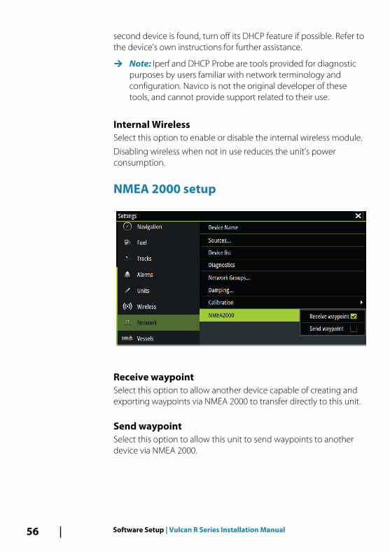
NMEA 2000 setup
Receive waypointSelect this option to allow another device capable of creating andexporting waypoints via NMEA 2000 to transfer directly to this unit.
Send waypointSelect this option to allow this unit to send waypoints to anotherdevice via NMEA 2000.
56 Software Setup | Vulcan R Series Installation Manual
Mercury®If the unit is on the same NMEA 2000 network as a MercuryVesselView® 4, 7, 403, 502, 702, 703, or Link, a host of Mercury®specific features are automatically unlocked on the unit. When thefeatures are enabled, the display may prompt the user for somebasic configuration information. Refer to the VesselView® manual orengine supplier for further information.
Software updates and data backupFrom time to time we release software updates to our existingproducts. Updates are created for a variety of reasons; to add orimprove features, to add support for new external devices, or to fixsoftware bugs.
Updates can be found on the website: www.bandg.com
When the unit is connected to the internet, a pop-up can appearadvising that a software update is available and encourages you todownload the update.
The unit may be used to apply software updates to itself, and tosupported network devices, with files read off a memory cardinserted in the card reader.
Before initiating an update to the unit itself, be sure to back up anypotentially valuable user data.
Network analyzer and service assistantThe system has a built-in service assistant that creates a report ofthe devices installed on the NMEA 2000 network such as thesoftware versions, serial numbers, and information from the settingsfile to assist in technical support enquiries.
To use the analyzer, open the About page of the System settingsdialog and select Support. Two options are displayed:
Create reportAnalyzes your network and prompts you for information requiredfor support and creates the report with information automaticallygathered from the network. You can add screenshots and log filesthat will be attached to the report. There is a 20MB limit for thereport attachments. You can save the report to a memory card andemail it to support or upload it directly if you have an internet
Software Setup | Vulcan R Series Installation Manual 57
connection. If you call technical support first, you can enter anincident number to assist with tracking.
Check system for updatesAnalyzes your network and checks if updates are available forcompatible devices.
Ú Note: Connect your unit to the internet to check for the latestavailable software versions. The software versions will be up todate as of the last time you updated your unit or connected tothe internet.
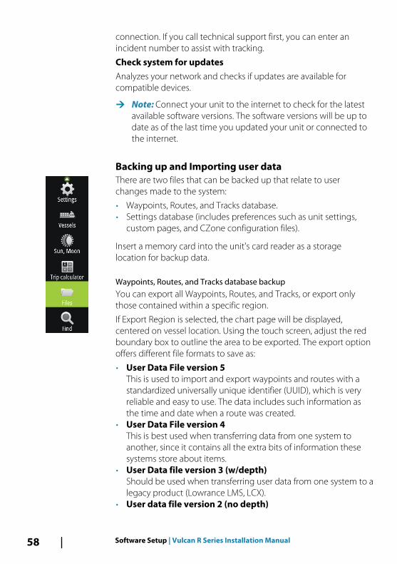
Backing up and Importing user dataThere are two files that can be backed up that relate to userchanges made to the system:
• Waypoints, Routes, and Tracks database.• Settings database (includes preferences such as unit settings,
custom pages, and CZone configuration files).
Insert a memory card into the unit's card reader as a storagelocation for backup data.
Waypoints, Routes, and Tracks database backupYou can export all Waypoints, Routes, and Tracks, or export onlythose contained within a specific region.
If Export Region is selected, the chart page will be displayed,centered on vessel location. Using the touch screen, adjust the redboundary box to outline the area to be exported. The export optionoffers different file formats to save as:
• User Data File version 5This is used to import and export waypoints and routes with astandardized universally unique identifier (UUID), which is veryreliable and easy to use. The data includes such information asthe time and date when a route was created.
• User Data File version 4This is best used when transferring data from one system toanother, since it contains all the extra bits of information thesesystems store about items.
• User Data file version 3 (w/depth)Should be used when transferring user data from one system to alegacy product (Lowrance LMS, LCX).
• User data file version 2 (no depth)
58 Software Setup | Vulcan R Series Installation Manual
Can be used when transferring user data from one system to alegacy product (Lowrance LMS, LCX).
• GPX (GPS Exchange, no depth)This is the format most used on the web that shares among mostGPS systems in the world. Use this format if you are taking data toa competitor's unit.
• Northstar.dat (no Tracks)Used to transfer data to a legacy Northstar device.
After you select the file type, select Export and destination memorycard. The receiving GPS/PC typically needs to be set to allow importof Waypoints.
Settings database exportSelect Setting database to export the Settings database, or exportCZone configuration (CZone installation dependent). Choose thedesired option and select the memory card destination.
Importing a databaseLater, if the unit has been restored to factory defaults or user data isaccidentally deleted, return to the files page, select the backed upfile, and then Import. View file details for creation date.
Software upgradesThe update file must be loaded to the root directory of the memorycard.
The update may be initiated at boot up: insert the memory card intothe card reader before turning the unit on, boot the unit, and followthe on-screen instructions.
Alternatively, in the Files menu, locate the update file on thememory card inserted in the card reader and select Upgrade,followed by This Display. Accept the prompt to reboot the unit,and wait a few moments as the unit restarts. Do not remove thememory card or repower the unit until the process is completed(this typically takes no more than a couple of minutes).
Software upgrade of remote deviceIt is possible to run an update remotely from one unit and apply itto another, provided they are on the NMEA network. This is onlypossible for units without a card slot.
Software Setup | Vulcan R Series Installation Manual 59
Remote updating is similar to updating a local unit; select the file onthe memory card and select the Upgrade option, followed byRemote Upgrade. Follow the onscreen options.
NMEA 2000 device upgradesThe update file must be loaded to the root directory of a memorycard inserted in the card reader.
1. Select the Files toolbar option and select the update file underMemory card.
2. Select the Upgrade option presented when the file ishighlighted. A list should appear displaying any compatibledevices the update file applies to. In most cases this will be asingle device.
Ú Note: If no device is shown, check that the device to beupdated has power, and run any outstanding updates for theunit first.
3. Select the device and initiate the upgrade. Do not interrupt theupgrade process.
60 Software Setup | Vulcan R Series Installation Manual
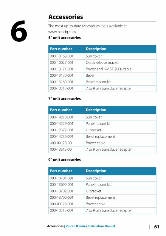
AccessoriesThe most up-to-date accessories list is available at:
www.bandg.com.
5" unit accessories
Part number Description
000-13168-001 Sun cover
000-10027-001 Quick release bracket
000-13171-001 Power and NMEA 2000 cable
000-13170-001 Bezel
000-13169-001 Panel mount kit
000-13313-001 7 to 9 pin transducer adapter
7" unit accessories
Part number Description
000-14228-001 Sun cover
000-14229-001 Panel mount kit
000-12372-001 U-bracket
000-14230-001 Bezel replacement
000-00128-00 Power cable
000-13313-00 7 to 9 pin transducer adapter
9" unit accessories
Part number Description
000-13701-001 Sun cover
000-13699-001 Panel mount kit
000-13702-001 U-bracket
000-13700-001 Bezel replacement
000-00128-001 Power cable
000-13313-001 7 to 9 pin transducer adapter
6
Accessories | Vulcan R Series Installation Manual 61
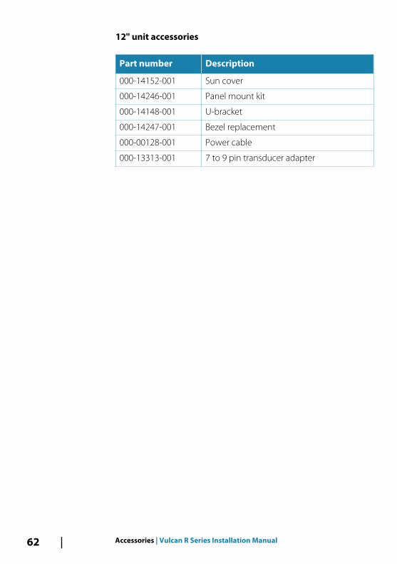
12" unit accessories
Part number Description
000-14152-001 Sun cover
000-14246-001 Panel mount kit
000-14148-001 U-bracket
000-14247-001 Bezel replacement
000-00128-001 Power cable
000-13313-001 7 to 9 pin transducer adapter
62 Accessories | Vulcan R Series Installation Manual
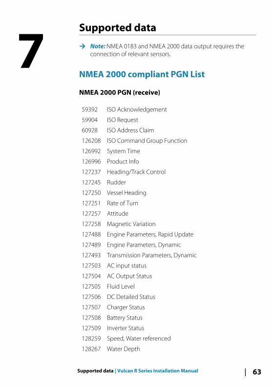
Supported data
Ú Note: NMEA 0183 and NMEA 2000 data output requires theconnection of relevant sensors.
NMEA 2000 compliant PGN List
NMEA 2000 PGN (receive)
59392 ISO Acknowledgement
59904 ISO Request
60928 ISO Address Claim
126208 ISO Command Group Function
126992 System Time
126996 Product Info
127237 Heading/Track Control
127245 Rudder
127250 Vessel Heading
127251 Rate of Turn
127257 Attitude
127258 Magnetic Variation
127488 Engine Parameters, Rapid Update
127489 Engine Parameters, Dynamic
127493 Transmission Parameters, Dynamic
127503 AC input status
127504 AC Output Status
127505 Fluid Level
127506 DC Detailed Status
127507 Charger Status
127508 Battery Status
127509 Inverter Status
128259 Speed, Water referenced
128267 Water Depth
7
Supported data | Vulcan R Series Installation Manual 63
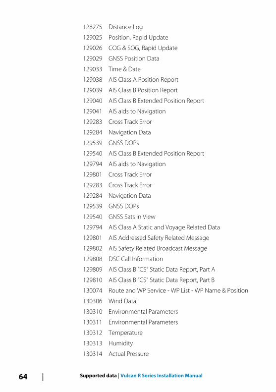
128275 Distance Log
129025 Position, Rapid Update
129026 COG & SOG, Rapid Update
129029 GNSS Position Data
129033 Time & Date
129038 AIS Class A Position Report
129039 AIS Class B Position Report
129040 AIS Class B Extended Position Report
129041 AIS aids to Navigation
129283 Cross Track Error
129284 Navigation Data
129539 GNSS DOPs
129540 AIS Class B Extended Position Report
129794 AIS aids to Navigation
129801 Cross Track Error
129283 Cross Track Error
129284 Navigation Data
129539 GNSS DOPs
129540 GNSS Sats in View
129794 AIS Class A Static and Voyage Related Data
129801 AIS Addressed Safety Related Message
129802 AIS Safety Related Broadcast Message
129808 DSC Call Information
129809 AIS Class B “CS” Static Data Report, Part A
129810 AIS Class B “CS” Static Data Report, Part B
130074 Route and WP Service - WP List - WP Name & Position
130306 Wind Data
130310 Environmental Parameters
130311 Environmental Parameters
130312 Temperature
130313 Humidity
130314 Actual Pressure
64 Supported data | Vulcan R Series Installation Manual
130576 Small Craft Status
130577 Direction Data
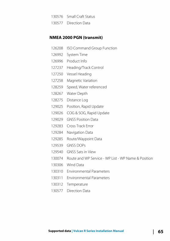
NMEA 2000 PGN (transmit)
126208 ISO Command Group Function
126992 System Time
126996 Product Info
127237 Heading/Track Control
127250 Vessel Heading
127258 Magnetic Variation
128259 Speed, Water referenced
128267 Water Depth
128275 Distance Log
129025 Position, Rapid Update
129026 COG & SOG, Rapid Update
129029 GNSS Position Data
129283 Cross Track Error
129284 Navigation Data
129285 Route/Waypoint Data
129539 GNSS DOPs
129540 GNSS Sats in View
130074 Route and WP Service - WP List - WP Name & Position
130306 Wind Data
130310 Environmental Parameters
130311 Environmental Parameters
130312 Temperature
130577 Direction Data
Supported data | Vulcan R Series Installation Manual 65
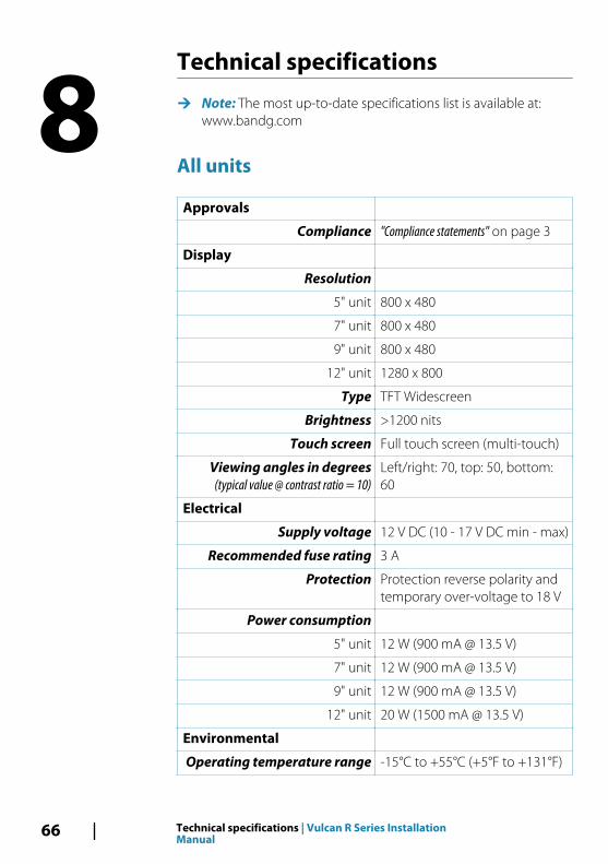
Technical specifications
Ú Note: The most up-to-date specifications list is available at:www.bandg.com
All units
Approvals
Compliance "Compliance statements" on page 3
Display
Resolution
5" unit 800 x 480
7" unit 800 x 480
9" unit 800 x 480
12" unit 1280 x 800
Type TFT Widescreen
Brightness >1200 nits
Touch screen Full touch screen (multi-touch)
Viewing angles in degrees(typical value @ contrast ratio = 10)
Left/right: 70, top: 50, bottom:60
Electrical
Supply voltage 12 V DC (10 - 17 V DC min - max)
Recommended fuse rating 3 A
Protection Protection reverse polarity andtemporary over-voltage to 18 V
Power consumption
5" unit 12 W (900 mA @ 13.5 V)
7" unit 12 W (900 mA @ 13.5 V)
9" unit 12 W (900 mA @ 13.5 V)
12" unit 20 W (1500 mA @ 13.5 V)
Environmental
Operating temperature range -15°C to +55°C (+5°F to +131°F)
8
66 Technical specifications | Vulcan R Series InstallationManual
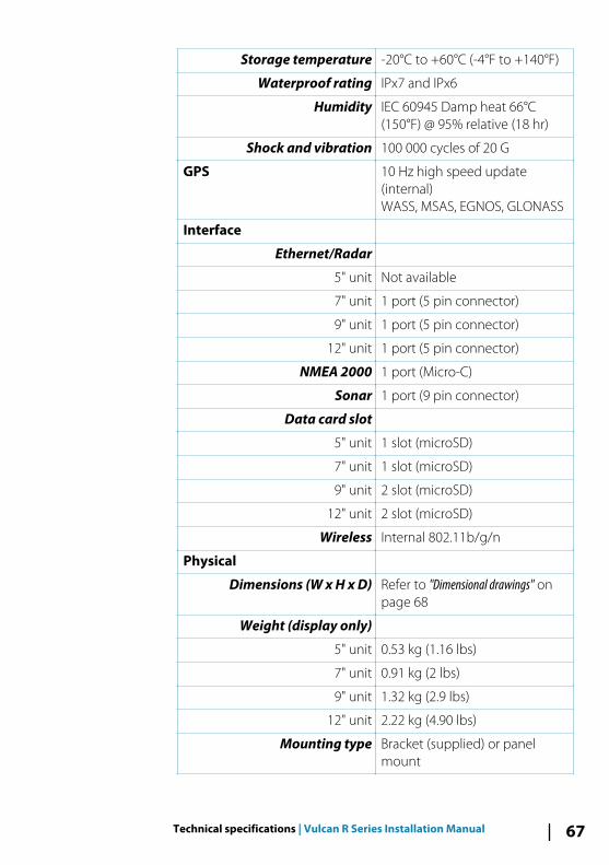
Storage temperature -20°C to +60°C (-4°F to +140°F)
Waterproof rating IPx7 and IPx6
Humidity IEC 60945 Damp heat 66°C(150°F) @ 95% relative (18 hr)
Shock and vibration 100 000 cycles of 20 G
GPS 10 Hz high speed update(internal)WASS, MSAS, EGNOS, GLONASS
Interface
Ethernet/Radar
5" unit Not available
7" unit 1 port (5 pin connector)
9" unit 1 port (5 pin connector)
12" unit 1 port (5 pin connector)
NMEA 2000 1 port (Micro-C)
Sonar 1 port (9 pin connector)
Data card slot
5" unit 1 slot (microSD)
7" unit 1 slot (microSD)
9" unit 2 slot (microSD)
12" unit 2 slot (microSD)
Wireless Internal 802.11b/g/n
Physical
Dimensions (W x H x D) Refer to "Dimensional drawings" onpage 68
Weight (display only)
5" unit 0.53 kg (1.16 lbs)
7" unit 0.91 kg (2 lbs)
9" unit 1.32 kg (2.9 lbs)
12" unit 2.22 kg (4.90 lbs)
Mounting type Bracket (supplied) or panelmount
Technical specifications | Vulcan R Series Installation Manual 67
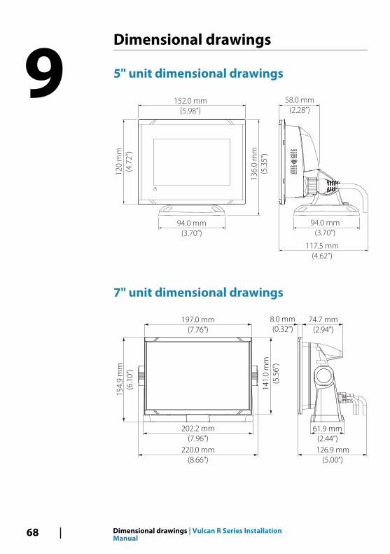
Dimensional drawings
5" unit dimensional drawings
152.0 mm
(5.98”)
94.0 mm
(3.70”)
12
0 m
m
(4.7
2”)
94.0 mm
(3.70”)
117.5 mm
(4.62”)
58.0 mm
(2.28”)
13
6.0
mm
(5.3
5”)
7" unit dimensional drawings
197.0 mm
(7.76”)
220.0 mm
(8.66”)
126.9 mm
(5.00”)
74.7 mm
(2.94”)
8.0 mm
(0.32”)
14
1.0
mm
(5.5
6”)
15
4.9
mm
(6.1
0”)
202.2 mm
(7.96”)
61.9 mm
(2.44”)
9
68 Dimensional drawings | Vulcan R Series InstallationManual
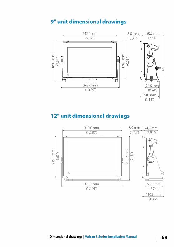
9" unit dimensional drawings
242.0 mm
(9.52”)
263.0 mm
(10.35”)
24.0 mm
(0.94”)
18
4.0
mm
(7.2
4”)
17
0.0
mm
(6.6
9”)
8.0 mm
(0.31”)
90.0 mm
(3.54”)
79.0 mm
(3.11”)
12" unit dimensional drawings
310.0 mm
(12.20“)
74.7 mm
(2.94“)
323.5 mm
(12.74“)
21
9.1
mm
(8.6
3“)
23
3.2
mm
(9.1
8“)
8.0 mm
(0.32“)
95.0 mm
(7.74“)
110.6 mm
(4.36“)
Dimensional drawings | Vulcan R Series Installation Manual 69

70 Dimensional drawings | Vulcan R Series InstallationManual


*988
-110
99-0
03*


![VULCAN HIGH SPEED DEEP FAT FRYER (ELECTRIC) › vulcan-website...Vulcan catering equipment (ptY)ltD [ 2 ] VULCAN HIGH SPEED DEEP FAT FRYER (ELECTRIC) GENERAL DATA: MANUFACTURER: Vulcan](https://img.pdfslide.us/doc/110x75/60c05ae5c355355f26327394/vulcan-high-speed-deep-fat-fryer-electric-a-vulcan-website-vulcan-catering.jpg)