Embed Size (px)
Citation preview
Following installation, please forward this manual to the appropriate operations person.
Installation, Operation and Service Manual
VU155N Series Ice and Water Dispensers
Order parts online www.follettice.com
Service numbers above B50000
00119602R07
801 Church Lane • Easton, PA 18040, USAToll free (877) 612-5086 • +1 (610) 252-7301www.follettice.com
Welcome to Follett Corporation Important cautionsSpecifications Installation Installing dispenser in counter Field wiring diagrams Installing optional ice machineOperation How the dispenser works CleaningService Dispense chute cover removal Auger motor assembly removal Gate assembly removal Auger and auger tube removal Dispenser wheel removal Wiring diagramsTroubleshootingReplacement parts
Table of contents
3346677888
101010101010121314
Welcome to FollettFollett equipment enjoys a well-deserved reputation for excellent performance, long-term reliability and outstanding after-the-sale support. To ensure that this dispenser delivers that same degree of service, we ask that you take a moment to review this manual before beginning the installation of the dispenser. Should you have any questions or require technical help at any point, please call our technical service group, (877) 612-5086 or +1 (610) 252-7301.
Before you beginAfter uncrating and removing all packing material, inspect the equipment for concealed shipping damage. If damage is found, notify the shipper immediately and contact Follett Corporation so that we can help in the filing of a claim, if necessary.
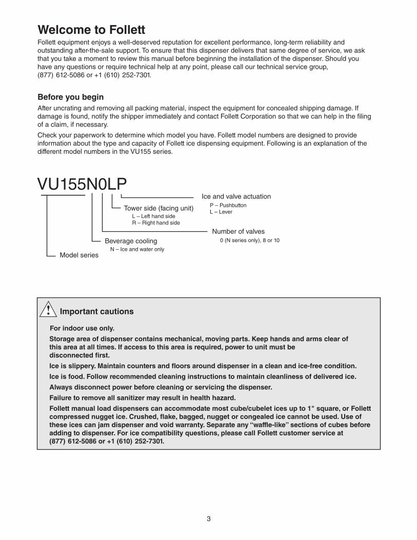
Check your paperwork to determine which model you have. Follett model numbers are designed to provide information about the type and capacity of Follett ice dispensing equipment. Following is an explanation of the different model numbers in the VU155 series.
VU155N0LP
Model series
Beverage coolingN – Ice and water only
Tower side (facing unit)L – Left hand sideR – Right hand side
Ice and valve actuationP – PushbuttonL – Lever
Number of valves0 (N series only), 8 or 10
3
Important cautions
For indoor use only.
Storage area of dispenser contains mechanical, moving parts. Keep hands and arms clear of this area at all times. If access to this area is required, power to unit must be disconnected first.
Ice is slippery. Maintain counters and floors around dispenser in a clean and ice-free condition.
Ice is food. Follow recommended cleaning instructions to maintain cleanliness of delivered ice.
Always disconnect power before cleaning or servicing the dispenser.
Failure to remove all sanitizer may result in health hazard.
Follett manual load dispensers can accommodate most cube/cubelet ices up to 1" square, or Follett compressed nugget ice. Crushed, flake, bagged, nugget or congealed ice cannot be used. Use of these ices can jam dispenser and void warranty. Separate any “waffle-like” sections of cubes before adding to dispenser. For ice compatibility questions, please call Follett customer service at (877) 612-5086 or +1 (610) 252-7301.
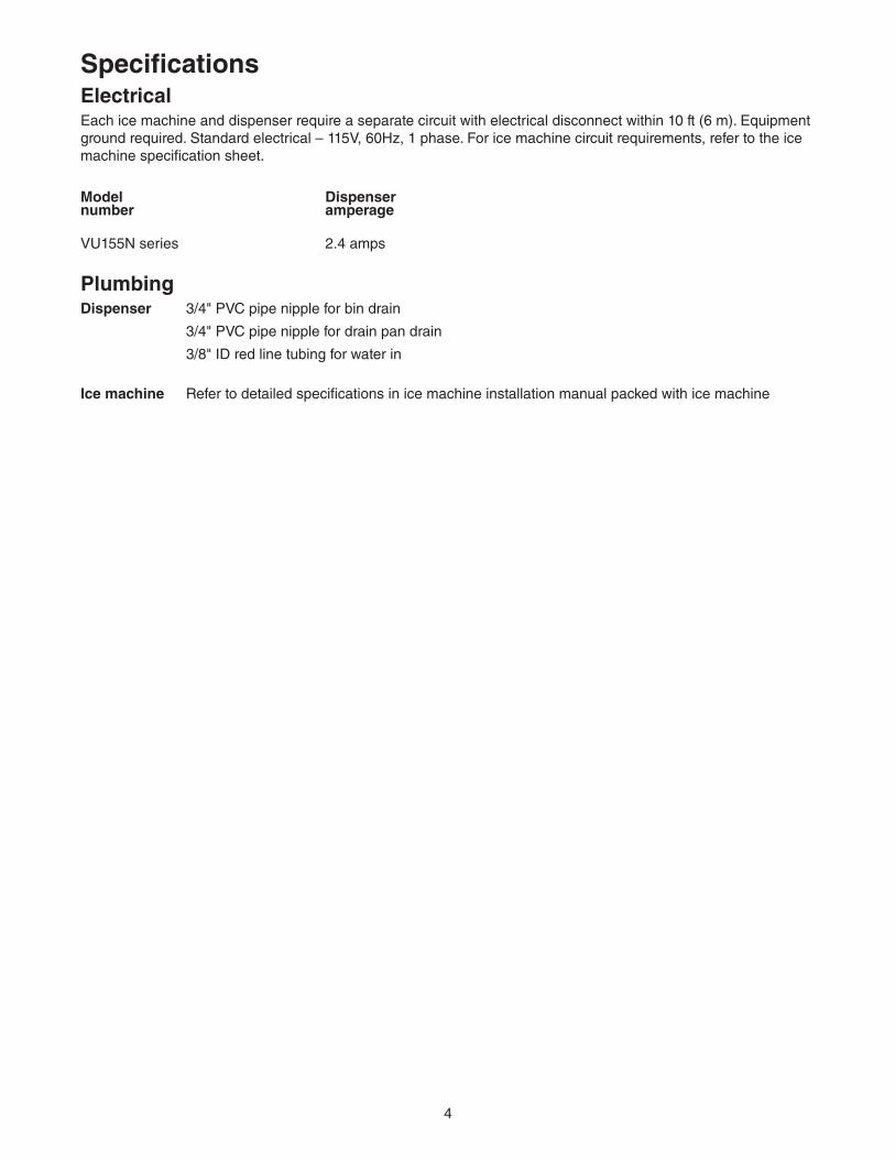
SpecificationsElectricalEach ice machine and dispenser require a separate circuit with electrical disconnect within 10 ft (6 m). Equipment ground required. Standard electrical – 115V, 60Hz, 1 phase. For ice machine circuit requirements, refer to the ice machine specification sheet.
Model Dispensernumber amperage
VU155N series 2.4 amps
Plumbing
Dispenser 3/4" PVC pipe nipple for bin drain
3/4" PVC pipe nipple for drain pan drain
3/8" ID red line tubing for water in
Ice machine Refer to detailed specifications in ice machine installation manual packed with ice machine
4
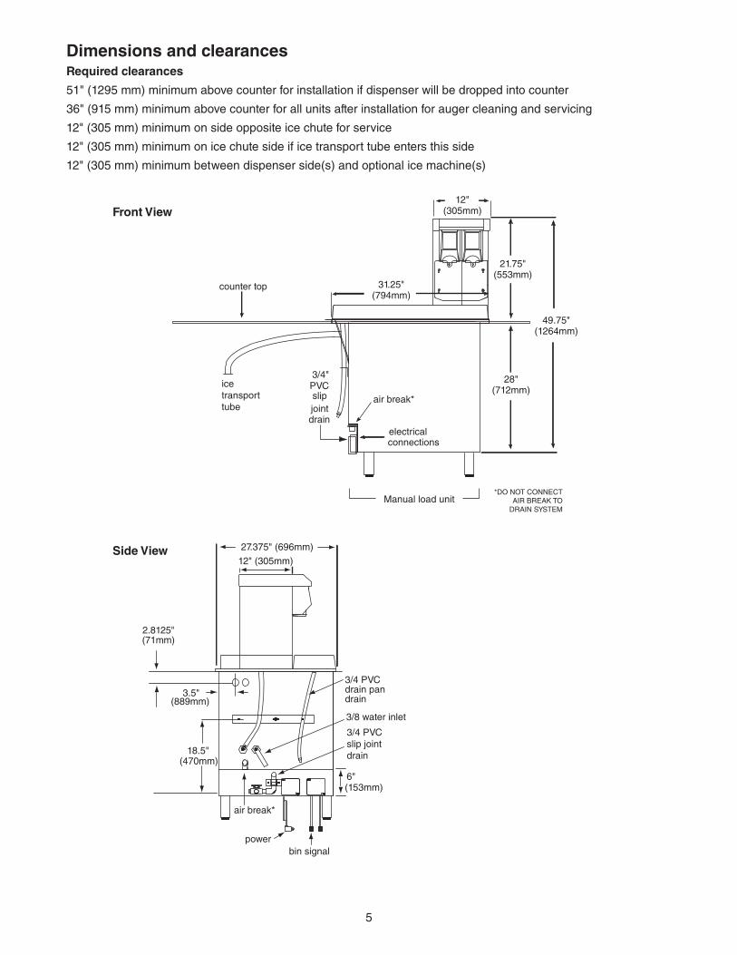
Dimensions and clearancesRequired clearances
51" (1295 mm) minimum above counter for installation if dispenser will be dropped into counter
36" (915 mm) minimum above counter for all units after installation for auger cleaning and servicing
12" (305 mm) minimum on side opposite ice chute for service
12" (305 mm) minimum on ice chute side if ice transport tube enters this side
12" (305 mm) minimum between dispenser side(s) and optional ice machine(s)
Front View
ice transport tube
Manual load unit*DO NOT CONNECT
AIR BREAK TODRAIN SYSTEM
PVC
jointdrain
slip
3/4"
air break*
electricalconnections
counter top
12"(305mm)
31.25"(794mm)
21.75"(553mm)
49.75"(1264mm)
28"(712mm)
Side View 27.375" (696mm)
12" (305mm)
18.5"(470mm)
3.5"(889mm)
bin signal power
6"(153mm)
3/4 PVCslip jointdrain
air break*
3/8 water inlet
3/4 PVCdrain pandrain
2.8125"(71mm)
5
InstallationInstalling dispenser in counterNote: All dispensers must be supported from below with supplied 6" – 9" (153 – 229 mm) adjustable leg accessory, or equivalent. Do not hang dispenser on flange.
All dispensers must be installed level in both directions to ensure proper operation.
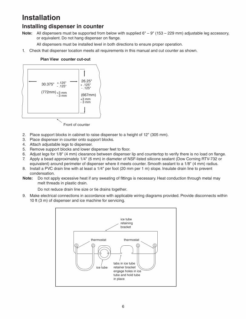
1. Check that dispenser location meets all requirements in this manual and cut counter as shown.
Plan View counter cut-out
2. Place support blocks in cabinet to raise dispenser to a height of 12" (305 mm). 3. Place dispenser in counter onto support blocks.4. Attach adjustable legs to dispenser.5. Remove support blocks and lower dispenser feet to floor.6. Adjust legs for 1/8" (4 mm) clearance between dispenser lip and countertop to verify there is no load on flange.7. Apply a bead approximately 1/4" (6 mm) in diameter of NSF-listed silicone sealant (Dow Corning RTV-732 or equivalent) around perimeter of dispenser where it meets counter. Smooth sealant to a 1/8" (4 mm) radius.8. Install a PVC drain line with at least a 1/4" per foot (20 mm per 1 m) slope. Insulate drain line to prevent condensation. Note: Do not apply excessive heat if any sweating of fittings is necessary. Heat conduction through metal may melt threads in plastic drain.
Do not reduce drain line size or tie drains together.
9. Make electrical connections in accordance with applicable wiring diagrams provided. Provide disconnects within 10 ft (3 m) of dispenser and ice machine for servicing.
6
26.25"
Front of counter
+.125" + .125" 30.375"
(772mm)+3 mm(667mm)
- .125"
+3 mm- 3 mm
- 3 mm
- .125"
Bin thermostat capillary tube mounting
tabs in ice tuberetainer bracketengage holes in icetube and hold tubein place
ice tube
ice tube retaining bracket
thermostatthermostat
ice tubeice tube retaining bracket thermostat
Front View, VU300Front View, VU155
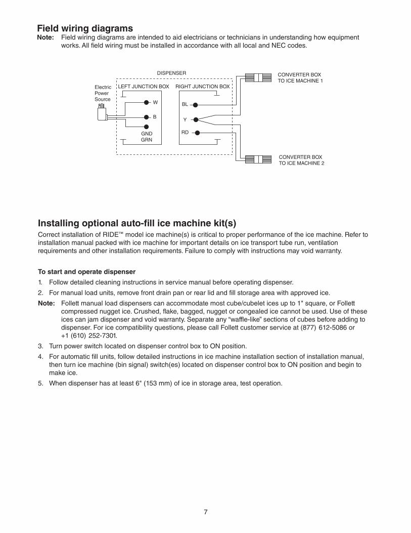
Field wiring diagramsNote: Field wiring diagrams are intended to aid electricians or technicians in understanding how equipment works. All field wiring must be installed in accordance with all local and NEC codes.
DISPENSER
LEFT JUNCTION BOX RIGHT JUNCTION BOX
BL
Y
RD
CONVERTER BOXTO ICE MACHINE 2
CONVERTER BOXTO ICE MACHINE 1
Electric Power Source
GNDGRN
B
W
Installing optional auto-fill ice machine kit(s)Correct installation of RIDE™ model ice machine(s) is critical to proper performance of the ice machine. Refer to installation manual packed with ice machine for important details on ice transport tube run, ventilation requirements and other installation requirements. Failure to comply with instructions may void warranty.
To start and operate dispenser
1. Follow detailed cleaning instructions in service manual before operating dispenser.
2. For manual load units, remove front drain pan or rear lid and fill storage area with approved ice.
Note: Follett manual load dispensers can accommodate most cube/cubelet ices up to 1" square, or Follett compressed nugget ice. Crushed, flake, bagged, nugget or congealed ice cannot be used. Use of these ices can jam dispenser and void warranty. Separate any “waffle-like” sections of cubes before adding to dispenser. For ice compatibility questions, please call Follett customer service at (877) 612-5086 or +1 (610) 252-7301.
3. Turn power switch located on dispenser control box to ON position.
4. For automatic fill units, follow detailed instructions in ice machine installation section of installation manual, then turn ice machine (bin signal) switch(es) located on dispenser control box to ON position and begin to make ice.
5. When dispenser has at least 6" (153 mm) of ice in storage area, test operation.
7
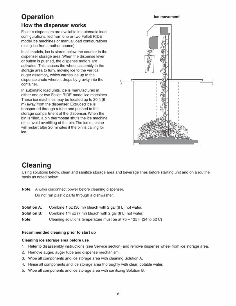
OperationHow the dispenser worksFollett’s dispensers are available in automatic load configurations, fed from one or two Follett RIDE model ice machines or manual load configurations (using ice from another source).
In all models, ice is stored below the counter in the dispenser storage area. When the dispense lever or button is pushed, the dispense motors are activated. This causes the wheel assembly in the storage area to turn, moving ice to the vertical auger assembly, which carries ice up to the dispense chute where it drops by gravity into the container.
In automatic load units, ice is manufactured in either one or two Follett RIDE model ice machines. These ice machines may be located up to 20 ft (6 m) away from the dispenser. Extruded ice is transported through a tube and pushed to the storage compartment of the dispenser. When the bin is filled, a bin thermostat shuts the ice machine off to avoid overfilling of the bin. The ice machine will restart after 20 minutes if the bin is calling for ice.
CleaningUsing solutions below, clean and sanitize storage area and beverage lines before starting unit and on a routine basis as noted below.
Note: Always disconnect power before cleaning dispenser.
Do not run plastic parts through a dishwasher.
Solution A: Combine 1 oz (30 ml) bleach with 2 gal (8 L) hot water.
Solution B: Combine 1/4 oz (7 ml) bleach with 2 gal (8 L) hot water.
Note: Cleaning solutions temperature must be at 75 – 125 F (24 to 52 C)
Recommended cleaning prior to start up
Cleaning ice storage area before use
1. Refer to disassembly instructions (see Service section) and remove dispense wheel from ice storage area.
2. Remove auger, auger tube and dispense mechanism.
3. Wipe all components and ice storage area with cleaning Solution A.
4. Rinse all components and ice storage area thoroughly with clear, potable water.
5. Wipe all components and ice storage area with sanitizing Solution B.
Ice movement
8
Recommended daily dispenser cleaning
1. Remove all debris from drain pan.
2. Pour 1 gallon (4 L) hot water into drain pan to keep drain lines clear.
Recommended weekly dispenser cleaning
1. Remove drain pan and grille and wash with Solution A. Rinse thoroughly.
2. Pour a solution of one cup (8 oz/237 ml) household bleach mixed with one gallon (3.8 L) hot water into drain pan to help prevent algae growth in drain lines.
Recommended quarterly dispenser cleaning
1. Remove top from dispenser and turn power switch to OFF position.
2. Remove ice from storage area.
3. Remove dispense chute cover, chute, auger motor assembly, auger and auger tube (see Service section).
4. Remove drain pan, grille and dispense wheel (see Service section).
5. Clean all components and bin storage area with Solution A, rinse thoroughly with clear water and sanitize with Solution B.
Putting unit back in service after quarterly cleaning
1. Reassemble components.
2. For manual load units, fill unit with an approved ice (see important cautions on page 4).
3. For automatic load units with MC400A/W (R404A refrigerant) ice machines, turn bin signal switch(es) and dispenser power switch to ON position and allow storage area to fill.
4. Dispense and discard all ice, verifying dispenser is functioning properly.
Recommended quarterly cleaning of optional ice machine.
Units equipped with optional ice machines require cleaning of ice machine system at least every six months, and more often if local water conditions dictate. Failure to clean ice machine system will result in decreased performance and potential damage to ice machine. Refer to Ice machine Installation, Operation and Service Manual.
9
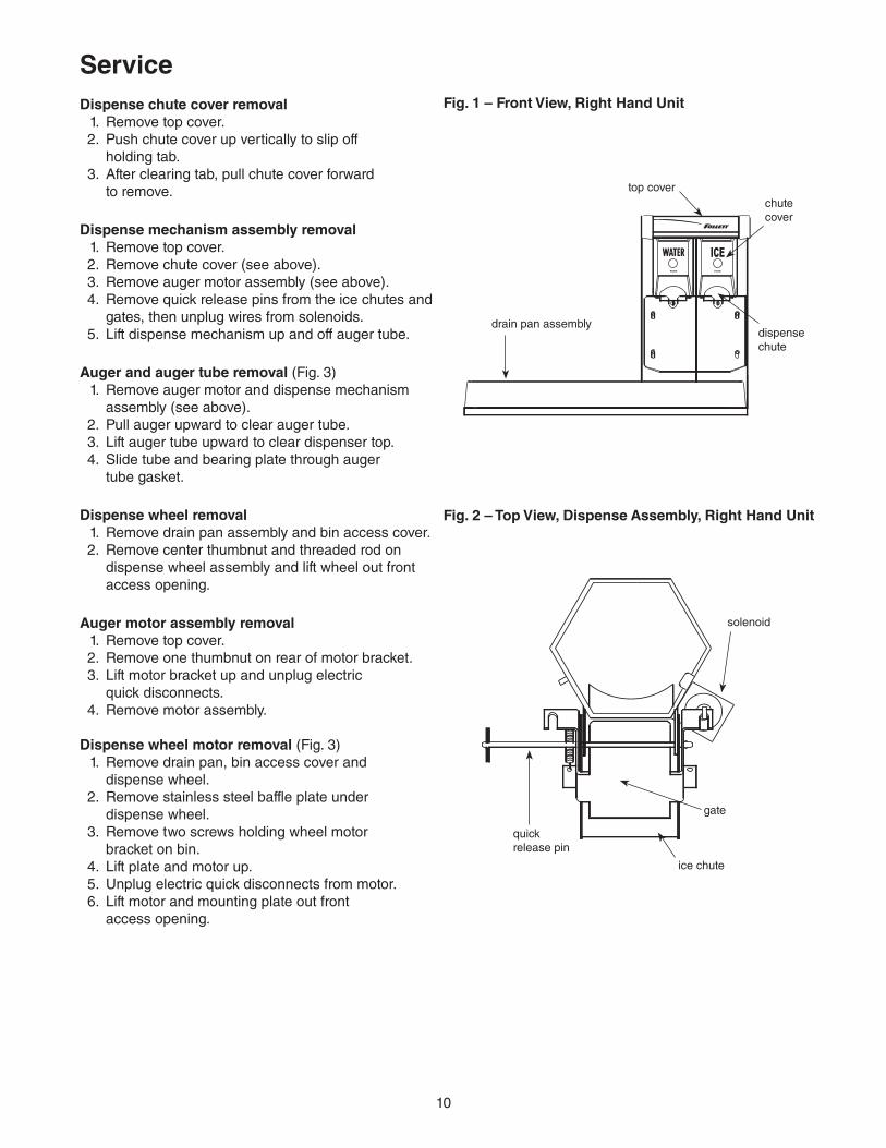
Dispense chute cover removal 1. Remove top cover. 2. Push chute cover up vertically to slip off holding tab. 3. After clearing tab, pull chute cover forward to remove.
Dispense mechanism assembly removal 1. Remove top cover. 2. Remove chute cover (see above). 3. Remove auger motor assembly (see above). 4. Remove quick release pins from the ice chutes and
gates, then unplug wires from solenoids. 5. Lift dispense mechanism up and off auger tube.
Auger and auger tube removal (Fig. 3) 1. Remove auger motor and dispense mechanism
assembly (see above). 2. Pull auger upward to clear auger tube. 3. Lift auger tube upward to clear dispenser top. 4. Slide tube and bearing plate through auger tube gasket.
Dispense wheel removal 1. Remove drain pan assembly and bin access cover. 2. Remove center thumbnut and threaded rod on
dispense wheel assembly and lift wheel out front access opening.
Auger motor assembly removal 1. Remove top cover. 2. Remove one thumbnut on rear of motor bracket. 3. Lift motor bracket up and unplug electric quick disconnects. 4. Remove motor assembly.
Dispense wheel motor removal (Fig. 3) 1. Remove drain pan, bin access cover and
dispense wheel. 2. Remove stainless steel baffle plate under
dispense wheel. 3. Remove two screws holding wheel motor
bracket on bin. 4. Lift plate and motor up. 5. Unplug electric quick disconnects from motor. 6. Lift motor and mounting plate out front
access opening.
solenoid
quick release pin
gate
Service
Fig. 2 – Top View, Dispense Assembly, Right Hand Unit
Fig. 1 – Front View, Right Hand Unit
dispense chute
drain pan assembly
chute cover
top cover
ice chute
10
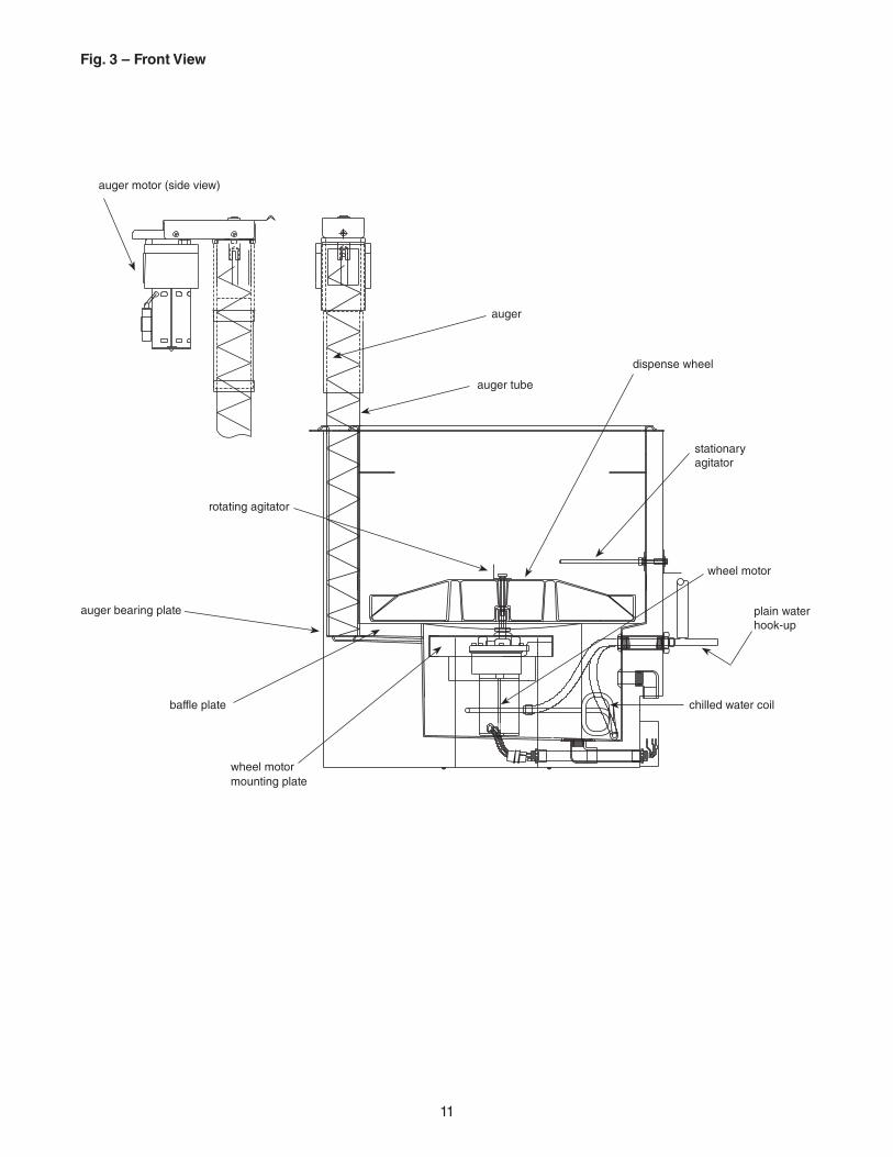
wheel motor
baffle plate
wheel motor mounting plate
dispense wheel
auger tube
auger
auger bearing plate
stationary agitator
rotating agitator
plain water hook-up
chilled water coil
Fig. 3 – Front View
11
auger motor (side view)
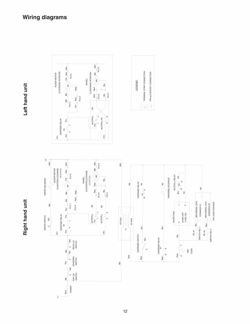
Wiring diagrams
PL3
-16
9
2Red6
RedRedR
ed
Blk
Brn
Yel
Red
24V
JU
NC
TIO
N B
OX
ICE
MA
KE
R #
2
BIN
SIG
NA
L (2
4V)
5 S
EC
ON
18 M
IN O
FF
Aut
oFill
Tim
er
Blu
Blu
32
ICE
MA
KE
R #
1
BIN
SIG
NA
L (2
4V)
31
Yel
Yel
AB
9
Brn
CN
O
Brn
B
115
Vol
ts
24 V
olts
Yel
Yel
A
Wht
Yel
Blk
Blk
L1
BLK
CN
O
Gry
CN
O
PL3
-2
PL2
-1
Red BluCO
UN
TE
RC
LOC
KW
ISE
CO
UN
TE
RC
LOC
KW
ISE
Pur
Orn
17
PL2
-3
Orn
CN
O
Orn
4
C
Pur
7
Pur
NO
Blk
PL3
-3Wht
Blu
Red
Blk
Red
Red
Wht
Wht
Blk
Blk
Ylw P
L2-2
L2
96
PIN
and
SO
CK
ET
CO
NN
EC
TIO
N
TE
RM
INA
L S
TR
IP C
ON
NE
CT
ION
LEG
EN
D:
PL3
-1
Red
Blk
CLO
CK
WIS
E R
OTA
TIO
N
CLO
CK
WIS
E R
OTA
TIO
N
Orn
Pur
17
PL3
-2 Blu
Red
Pur
PL2
-3
Red
Pur
Orn O
rn
47
Blk
PL2
-1
Blk
Blu
PL3
-3Wht
Red
Ylw P
L2-2
RO
TAT
ION
RO
TAT
ION
DIS
PE
NS
E S
WIT
CH
DIS
PE
NS
E R
ELA
Y
BIN
T-S
TAT
IM_#
2
SW
ITC
H N
O. 2
SW
ITC
H N
O. 1
IM_#
1
AU
TOF
ILL
RE
LAY
R2
DIS
PE
NS
E R
ELA
Y
DIS
PE
NS
E S
OLE
NO
ID
R1
R1
T1
SW
ITC
HS
WIT
CH
PO
WE
R
TOP
LID
DR
AIN
PAN
WAT
ER
SO
LEN
OID
AU
TOF
ILL
AU
TOF
ILL
SW
ITC
H
R2R2
DIS
PE
NS
E R
ELA
Y
WAT
ER
SW
ITC
H
RE
AR
LID
R1
M2
WH
EE
L
AU
GE
R M
OTO
R
M1
R2
R2
AU
TOF
ILL
AU
TOF
ILL
DIS
PE
NS
E R
ELA
Y
R1
M2
WH
EE
L
M1
AU
GE
R M
OTO
R
Wht
Wht
Wht
Rig
ht
han
d u
nit
Lef
t h
and
un
it
12
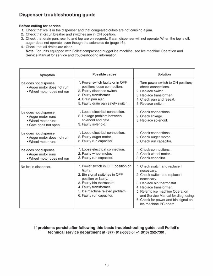
Symptom
Ice does not dispense. • Auger motor does not run • Wheel motor does not run
Ice does not dispense. • Auger motor runs • Wheel motor runs • Gate does not open
Ice does not dispense. • Auger motor does not run • Wheel motor runs
Ice does not dispense. • Auger motor runs • Wheel motor does not run
No ice in dispenser.
Possible cause
1. Power switch faulty or in OFF position; loose connection.
2. Faulty dispense switch. 3. Faulty transformer. 4. Drain pan ajar. 5. Faulty drain pan safety switch.
1. Loose electrical connection. 2. Linkage problem between
solenoid and gate. 3. Faulty solenoid.
1. Loose electrical connection. 2. Faulty auger motor. 3. Faulty run capacitor.
1. Loose electrical connection. 2. Faulty wheel motor. 3. Faulty run capacitor.
1. Power switch in OFF position or faulty.
2. Bin signal switches in OFF position or faulty.
3. Faulty bin thermostat. 4. Faulty transformer. 5. Ice machine related problem. 6. Faulty run capacitor.
Solution 1. Turn power switch to ON position;
check connections. 2. Replace switch. 3. Replace transformer. 4. Check pan and reseat. 5. Replace switch.
1. Check connections. 2. Check linkage. 3. Replace solenoid.
1. Check connections. 2. Check auger motor. 3. Check run capacitor.
1. Check connections. 2. Check wheel motor. 3. Check capacitor.
1. Check switch and replace if necessary.
2. Check switch and replace if necessary.
3. Replace bin thermostat. 4. Replace transformer. 5. Refer to ice machine Operation
and Service Manual for diagnosing. 6. Check for power and bin signal on
ice machine PC board.
13
Dispenser troubleshooting guide
Before calling for service 1. Check that ice is in the dispenser and that congealed cubes are not causing a jam. 2. Check that circuit breaker and switches are in ON position. 3. Check that drain pan, rear lid and top are on securely. If ajar, dispenser will not operate. When the top is off,
auger does not operate, even though the solenoids do (page 16). 4. Check that all drains are clear. Note: For units equipped with Follett compressed nugget ice machine, see Ice machine Operation and
Service Manual for service and troubleshooting information.
If problems persist after following this basic troubleshooting guide, call Follett’s technical service department at (877) 612-5086 or +1 (610) 252-7301.
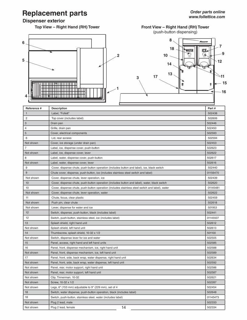
Reference # Description Part #
1 Label, “Follett” 502438
2 Top cover (includes label) 502606
3 Drain pan 502446
4 Grille, drain pan 502450
5 Cover, electrical components 502593
6 Lid, rear access 502594
Not shown Cover, ice storage (under drain pan) 502453
7 Label, ice, dispense cover, push-button 502623
Not shown Label, ice, dispense cover, lever 502622
8 Label, water, dispense cover, push-button 502617
Not shown Label, water, dispense cover, lever 502616
9 Cover, dispense chute, push-button operation (includes button and label), ice, black switch 502440
9 Chute cover, dispense, push-button, ice (includes stainless steel switch and label) 01156470
Not shown Cover, dispense chute, lever operation, ice 502439
10 Cover, dispense chute, push-button operation (includes button and label), water, black switch 502620
10 Cover, dispense chute, push-button operation (includes stainless steel switch and label), water 01145481
Not shown Cover, dispense chute, lever operation, water 502622
11 Chute, focus, clear plastic 502459
Not shown Push pin, clear chute 502618
Not shown Lever, dispense for water and ice 501953
12 Switch, dispense, push-button, black (includes label) 502441
12 Switch, push-button, stainless steel, ice (includes label) 01145507
13 Splash shield, right hand unit 502612
Not shown Splash shield, left hand unit 502613
14 Thumbscrew, splash shield, 10-32 x 1/2 501100
Not shown Switch, dispense lever for ice and water 502505
15 Panel, access, right hand and left hand units 502585
16 Panel, front, dispense mechanism, ice, right hand unit 502588
Not shown Panel, front, dispense mechanism, ice, left hand unit 502589
17 Panel, front, side, back wrap, water dispense, right hand unit 502634
Not shown Panel, front, side, back wrap, water dispense, left hand unit 502592
Not shown Panel, rear, motor support, right hand unit 502586
Not shown Panel, rear, motor support, left hand unit 502587
Not shown Clip, Tinnerman, 10-32 502621
Not shown Screw, 10-32 x 1/2 502287
Not shown Legs, 6" (153 mm) adjustable to 9" (229 mm), set of 4 502454
18 Switch, water dispense, push-button operation, black (includes label) 502648
18 Switch, push-button, stainless steel, water (includes label) 01145473
Not shown Plug 2 lead, male 502333
Not shown Plug 2 lead, female 502334
Top View – Right Hand (RH) Tower Front View – Right Hand (RH) Tower (push-button dispensing)
5
4
2
1
133
14
10
7
11
186
8
15
12
9
16
17
14
Replacement partsDispenser exterior
Order parts onlinewww.follettice.com
Side View (RH unit shown)
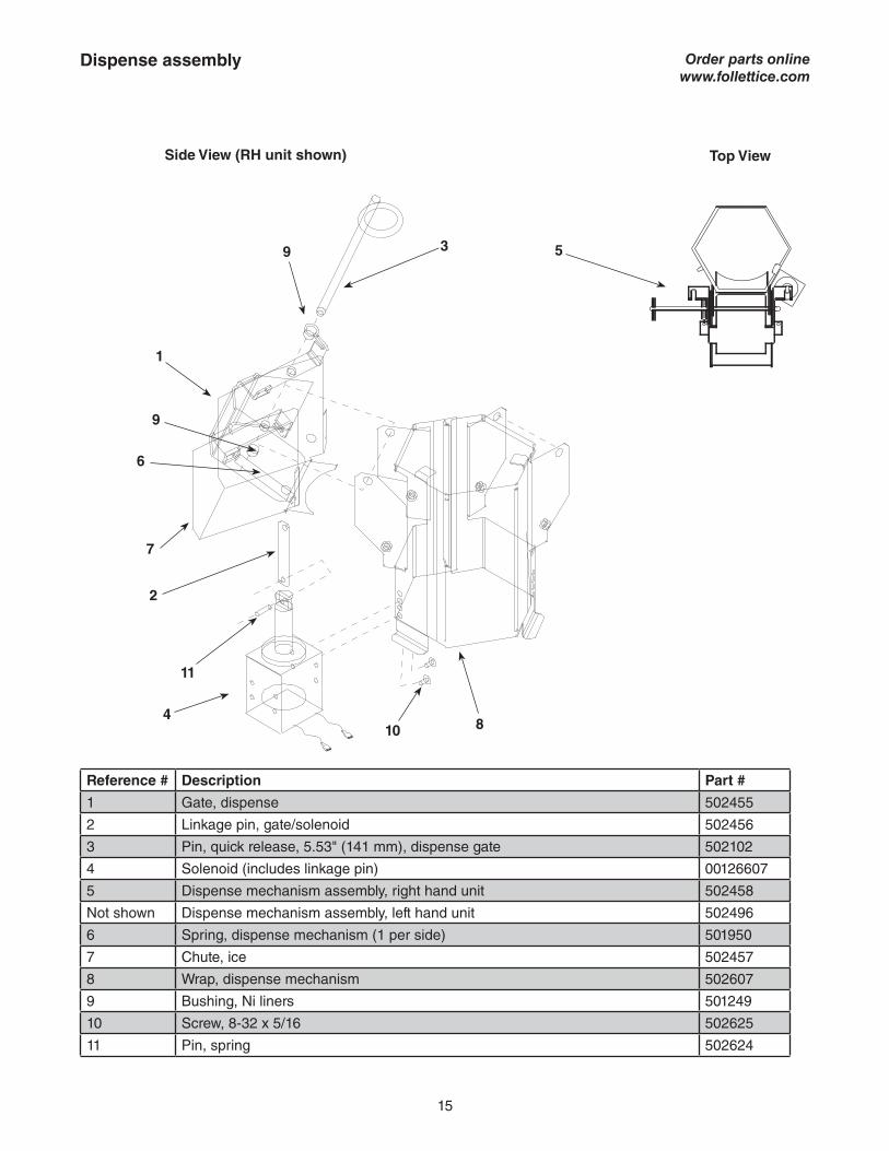
Reference # Description Part #
1 Gate, dispense 502455
2 Linkage pin, gate/solenoid 502456
3 Pin, quick release, 5.53" (141 mm), dispense gate 502102
4 Solenoid (includes linkage pin) 00126607
5 Dispense mechanism assembly, right hand unit 502458
Not shown Dispense mechanism assembly, left hand unit 502496
6 Spring, dispense mechanism (1 per side) 501950
7 Chute, ice 502457
8 Wrap, dispense mechanism 502607
9 Bushing, Ni liners 501249
10 Screw, 8-32 x 5/16 502625
11 Pin, spring 502624
1
2
3
4
6
7
8
9
10
11
9
15
5
Top View
Order parts onlinewww.follettice.com
Dispense assembly
Reference # Description Part #
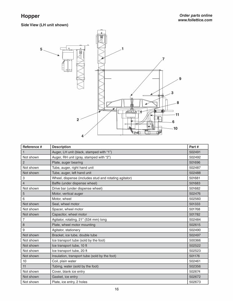
1 Auger, LH unit (black, stamped with “1”) 502491
Not shown Auger, RH unit (gray, stamped with “2”) 502492
2 Plate, auger bearing 501696
Not shown Tube, auger, right hand unit 502487
Not shown Tube, auger, left hand unit 502488
3 Wheel, dispense (includes stud and rotating agitator) 501681
4 Baffle (under dispense wheel) 501683
Not shown Drive bar (under dispense wheel) 501682
5 Motor, vertical auger 502476
6 Motor, wheel 502560
Not shown Seal, wheel motor 501333
Not shown Spacer, wheel motor 501768
Not shown Capacitor, wheel motor 501782
7 Agitator, rotating, 21" (534 mm) long 502484
8 Plate, wheel motor mounting 502615
9 Agitator, stationery 502490
Not shown Bracket, ice tube, double tube 502497
Not shown Ice transport tube (sold by the foot) 500366
Not shown Ice transport tube, 10 ft 502522
Not shown Ice transport tube, 20 ft 502523
Not shown Insulation, transport tube (sold by the foot) 501176
10 Coil, plain water 502461
11 Tubing, water (sold by the foot) 502356
Not shown Cover, blank ice entry 502674
Not shown Gasket, ice entry 502672
Not shown Plate, ice entry, 2 holes 502673
Hopper
9
6
7
4
8
3
15
2
10
11
16
Order parts onlinewww.follettice.com
Side View (LH unit shown)
Reference # Description Part #
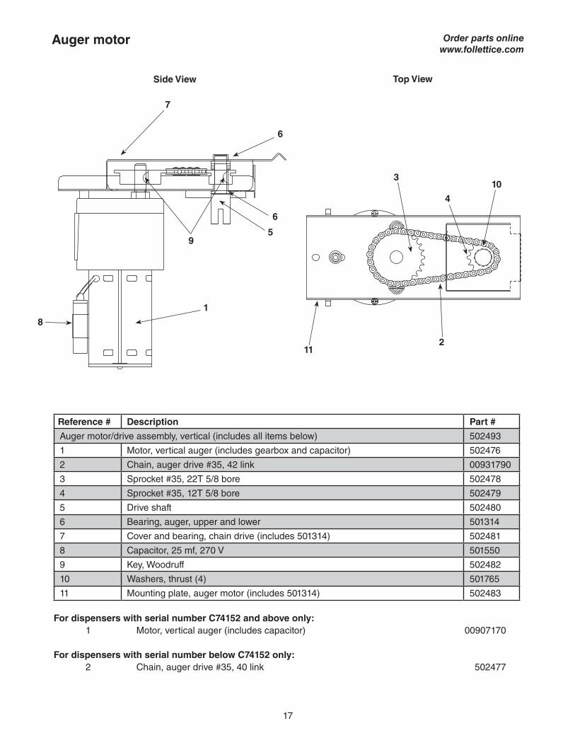
Auger motor/drive assembly, vertical (includes all items below) 502493
1 Motor, vertical auger (includes gearbox and capacitor) 502476
2 Chain, auger drive #35, 42 link 00931790
3 Sprocket #35, 22T 5/8 bore 502478
4 Sprocket #35, 12T 5/8 bore 502479
5 Drive shaft 502480
6 Bearing, auger, upper and lower 501314
7 Cover and bearing, chain drive (includes 501314) 502481
8 Capacitor, 25 mf, 270 V 501550
9 Key, Woodruff 502482
10 Washers, thrust (4) 501765
11 Mounting plate, auger motor (includes 501314) 502483
For dispensers with serial number C74152 and above only: 1 Motor, vertical auger (includes capacitor) 00907170
For dispensers with serial number below C74152 only: 2 Chain, auger drive #35, 40 link 502477
Auger motor
7
6
1
8
4
3
211
10
5
Side View Top View
9
6
17
Order parts onlinewww.follettice.com
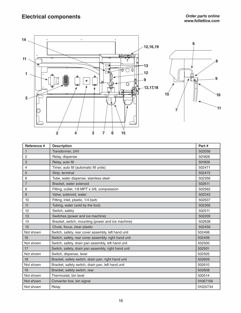
Reference # Description Part #
1 Transformer, 24V 502058
2 Relay, dispense 501826
3 Relay, auto fill 501826
4 Timer, auto fill (automatic fill units) 502471
5 Strip, terminal 502472
6 Tube, water dispense, stainless steel 502356
7 Bracket, water solenoid 502611
8 Fitting, outlet, 1/8 MPT x 3/8, compression 502562
9 Valve, solenoid, water 502243
10 Fitting, inlet, plastic, 1/4 barb 502637
11 Tubing, water (sold by the foot) 502356
12 Switch, safety 502511
13 Switches (power and ice machine) 502209
14 Bracket, switch, mounting (power and ice machine) 502638
15 Chute, focus, clear plastic 502459
Not shown Switch, safety, rear cover assembly, left hand unit 502498
16 Switch, safety, rear cover assembly, right hand unit 502499
Not shown Switch, safety, drain pan assembly, left hand unit 502500
17 Switch, safety, drain pan assembly, right hand unit 502501
Not shown Switch, dispense, lever 502505
18 Bracket, safety switch, drain pan, right hand unit 502609
Not shown Bracket, safety switch, drain pan, left hand unit 502610
19 Bracket, safety switch, rear 502608
Not shown Thermostat, bin level 500514
Not shown Converter box, bin signal 01067156
Not shown Relay 01020734
Electrical components
11
1
5
2 4 3 7 6 15
12,17,18
9
12
13
12,16,19
14
15
6
8
9
10
117
18
Order parts onlinewww.follettice.com

19
This page intentionally left blank.
00119602R07© Follett LLC 12/16
801 Church Lane • Easton, PA 18040, USAToll free (877) 612-5086 • +1 (610) 252-7301www.follettice.com
RIDE is a trademark of Follett LLC.Follett and Chewblet are registered trademarks of Follett LLC, registered in the US.


![Ken Follett - Saginaw Valley State University...Ken Follett From: Daniel Starer [dstarer@researchforwriters.com] Sent: 07 November 2000 16:34 To: Ken Follett Subject: 2of3 Dear Ken,](https://img.pdfslide.us/doc/110x75/611243a026737230c3353da1/ken-follett-saginaw-valley-state-ken-follett-from-daniel-starer-dstarerresearchforwriterscom.jpg)