Embed Size (px)
Citation preview
VS1 VIDEO SWITCHER INTERFACE
OPERATING INSTRUCTIONS and trouble-shooting guide
LECTROSONICS INC Rio Rancho NM
INTRODUCTION
The VS1 Video Switcher Interface is a microprocessor-based controller used between an automatic microphone mixer and a video switcher The VS1 provides sophisticated capabilities to synchronize video recording (with up to 8 video cameras) to the audio being recorded using the logic output capability of an automatic mixer Typical applications for the VS1 are in audiovideo teleconferencing courtroom video recording and security applications
The VS1 is fully programmable from front panel controls and may be quickly and simply set up for optimum performance in a variety of applications Input and output connections are standard screw type terminal strips for ease of installation The Auto-Sync capability of the VS1 allows camera switching during the vertical retrace interval for video systems which are synchronized to an external timebase This eliminates any rolling or other video anomalies as different cameras are activated
TABLE OF CONTENTS
INTRODUCTION 2
THEORY OF OPERATION 3
VS1 FUNCTIONS 4
VS1 Function Summary and Default Settings 5
FRONT PANEL DESCRIPTION 6
REAR PANEL DESCRIPTION 6
INSTALLATION 7
SETUP PROCEDURE 8
TROUBLESHOOTING 10
SPECIFICATIONS 10
SERVICE AND REPAIR 11
RETURNING UNITS FOR REPAIR 11
WARRANTY Back cover
VS1MAN 0993 2
THEORY OF OPERATION
The general operation of the VS1 will be described in this section while the specifics of each programmable option will be outlined in the Operating Instructions
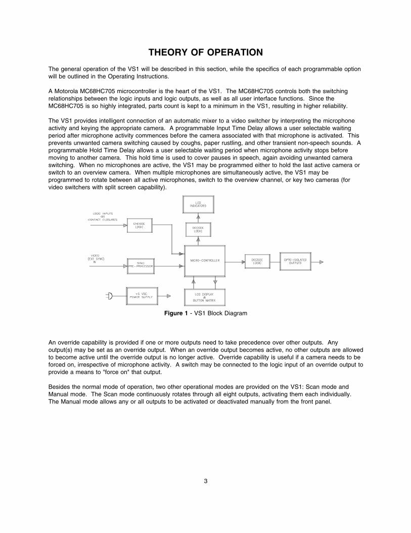
A Motorola MC68HC705 microcontroller is the heart of the VS1 The MC68HC705 controls both the switching relationships between the logic inputs and logic outputs as well as all user interface functions Since the MC68HC705 is so highly integrated parts count is kept to a minimum in the VS1 resulting in higher reliability
The VS1 provides intelligent connection of an automatic mixer to a video switcher by interpreting the microphone activity and keying the appropriate camera A programmable Input Time Delay allows a user selectable waiting period after microphone activity commences before the camera associated with that microphone is activated This prevents unwanted camera switching caused by coughs paper rustling and other transient non-speech sounds A programmable Hold Time Delay allows a user selectable waiting period when microphone activity stops before moving to another camera This hold time is used to cover pauses in speech again avoiding unwanted camera switching When no microphones are active the VS1 may be programmed either to hold the last active camera or switch to an overview camera When multiple microphones are simultaneously active the VS1 may be programmed to rotate between all active microphones switch to the overview channel or key two cameras (for video switchers with split screen capability)
Figure 1 - VS1 Block Diagram
An override capability is provided if one or more outputs need to take precedence over other outputs Any output(s) may be set as an override output When an override output becomes active no other outputs are allowed to become active until the override output is no longer active Override capability is useful if a camera needs to be forced on irrespective of microphone activity A switch may be connected to the logic input of an override output to provide a means to force on that output
Besides the normal mode of operation two other operational modes are provided on the VS1 Scan mode and Manual mode The Scan mode continuously rotates through all eight outputs activating them each individually The Manual mode allows any or all outputs to be activated or deactivated manually from the front panel
3
VS1 FUNCTIONS
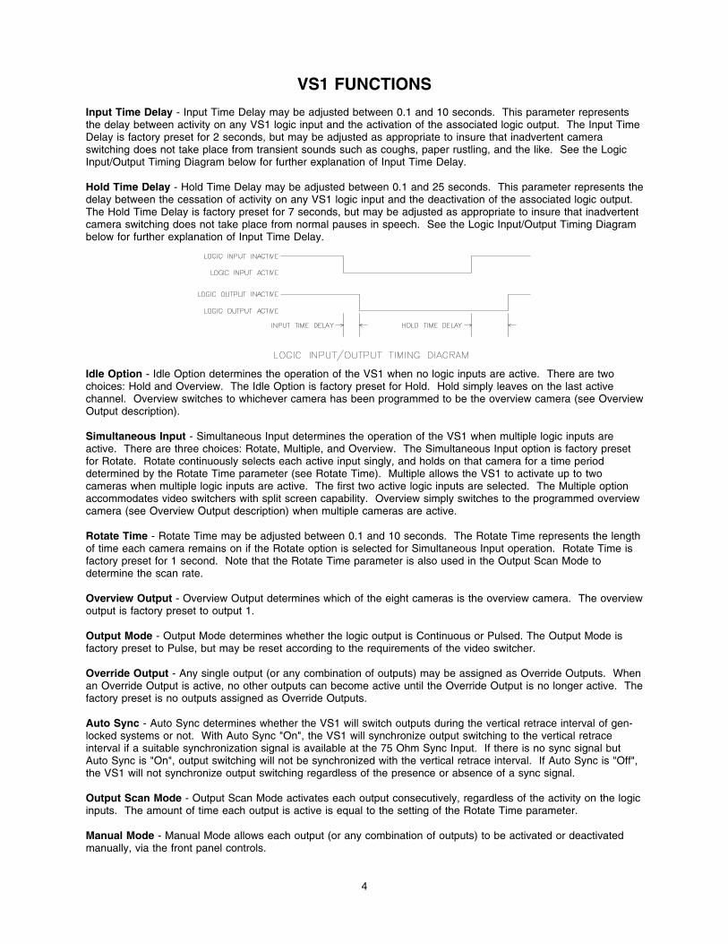
Input Time Delay - Input Time Delay may be adjusted between 01 and 10 seconds This parameter represents the delay between activity on any VS1 logic input and the activation of the associated logic output The Input Time Delay is factory preset for 2 seconds but may be adjusted as appropriate to insure that inadvertent camera switching does not take place from transient sounds such as coughs paper rustling and the like See the Logic InputOutput Timing Diagram below for further explanation of Input Time Delay
Hold Time Delay - Hold Time Delay may be adjusted between 01 and 25 seconds This parameter represents the delay between the cessation of activity on any VS1 logic input and the deactivation of the associated logic output The Hold Time Delay is factory preset for 7 seconds but may be adjusted as appropriate to insure that inadvertent camera switching does not take place from normal pauses in speech See the Logic InputOutput Timing Diagram below for further explanation of Input Time Delay
Idle Option - Idle Option determines the operation of the VS1 when no logic inputs are active There are two choices Hold and Overview The Idle Option is factory preset for Hold Hold simply leaves on the last active channel Overview switches to whichever camera has been programmed to be the overview camera (see Overview Output description)
Simultaneous Input - Simultaneous Input determines the operation of the VS1 when multiple logic inputs are active There are three choices Rotate Multiple and Overview The Simultaneous Input option is factory preset for Rotate Rotate continuously selects each active input singly and holds on that camera for a time period determined by the Rotate Time parameter (see Rotate Time) Multiple allows the VS1 to activate up to two cameras when multiple logic inputs are active The first two active logic inputs are selected The Multiple option accommodates video switchers with split screen capability Overview simply switches to the programmed overview camera (see Overview Output description) when multiple cameras are active
Rotate Time - Rotate Time may be adjusted between 01 and 10 seconds The Rotate Time represents the length of time each camera remains on if the Rotate option is selected for Simultaneous Input operation Rotate Time is factory preset for 1 second Note that the Rotate Time parameter is also used in the Output Scan Mode to determine the scan rate
Overview Output - Overview Output determines which of the eight cameras is the overview camera The overview output is factory preset to output 1
Output Mode - Output Mode determines whether the logic output is Continuous or Pulsed The Output Mode is factory preset to Pulse but may be reset according to the requirements of the video switcher
Override Output - Any single output (or any combination of outputs) may be assigned as Override Outputs When an Override Output is active no other outputs can become active until the Override Output is no longer active The factory preset is no outputs assigned as Override Outputs
Auto Sync - Auto Sync determines whether the VS1 will switch outputs during the vertical retrace interval of genshylocked systems or not With Auto Sync On the VS1 will synchronize output switching to the vertical retrace interval if a suitable synchronization signal is available at the 75 Ohm Sync Input If there is no sync signal but Auto Sync is On output switching will not be synchronized with the vertical retrace interval If Auto Sync is Off the VS1 will not synchronize output switching regardless of the presence or absence of a sync signal
Output Scan Mode - Output Scan Mode activates each output consecutively regardless of the activity on the logic inputs The amount of time each output is active is equal to the setting of the Rotate Time parameter
Manual Mode - Manual Mode allows each output (or any combination of outputs) to be activated or deactivated manually via the front panel controls
4
VS1 Function Summary and Default Settings
(Version 12 firmware)
Feature Function Range Factory Default
Input Time Delay Outputs 1 thru 8 01 to 100 20
Hold Time Delay Outputs 1 thru 8 01 to 250 70
Idle Option Hold Overview Hold
Simultaneous Input Rotate Overview Multiple Rotate
Rotate Time 01 to 100 10
Overview Output 1 thru 8 1
Output Mode Pulse Continuous Pulse
Override Output Outputs 1 thru 8 Yes No No
Auto Sync On Off On
Output Scan Mode Active Output 1 thru 8
(Informational display only)
1 thru 8 (Scan rate is equal to the
Rotate Time setting)
Manual Mode Outputs 1 thru 8 On Off Off
5
FRONT PANEL DESCRIPTION
SELECT PUSHBUTTON - Selects the area on the LCD display for which the Up and Down pushbuttons are active The blinking cursor will be placed in the selected area The first line of the display is the name of the selected function The second line of the display shows the selected channel and also the current value of the selected function
UP and DOWN PUSHBUTTONS - Allows the VS1 to be cycled through its function options as well as enabling the function values to be changed
SAVE PUSHBUTTON - Allows the current value of the selected function to be saved to permanent memory
ACTIVE OUTPUT LEDS - Indicate which logic output(s) are currently active
POWER LED - Indicates the presence of AC power to the DC1
POWER SWITCH - Turns the VS1 on or off
Figure 3 - VS1 Front Panel
REAR PANEL DESCRIPTION
LOGIC OUTPUT CONNECTORS - provide an isolated activation signal suitable for interface with a video switcher
LOGIC INPUT CONNECTORS - provide a means by which logic outputs from another source (like an automatic mixer) may be connected to the VS1
75 OHM SYNC INPUT - provides an input to accept the system synchronization signal (if one is present) to allow the VS1 to initiate camera switching only during the vertical retrace interval
Figure 4 - VS1 Rear Panel
6
INSTALLATION
The VS1 has eight logic inputs eight logic outputs and a video synchronization input The logic inputs provide the interface to an automatic microphone mixer (or other device that generates logic output signals) The logic inputs will accept a switch or relay contact closure or a saturated transistor (eg an optically isolated LED-Phototransistor combination) The video synchronization input accepts a gen-lock signal from a master timebase and strips the vertical retrace pulse This allows the VS1 to key the video switcher for a camera change without introducing any rolling or other video anomalies associated with non-synchronized video switching
Installation of the VS1 is quite straightforward The following instructions assume the use of a Lectrosonics AC1AP4 Automatic Mixer or VS1 Automatic Pre-Processor but the VS1 is compatible with virtually all automatic mixers that provide logic outputs If a non-Lectrosonics automatic mixer is to be used with the VS1 please consult the factory for interconnection details
Logic outputs from an automatic mixer are connected to the logic input terminals of the VS1 Note that multiple logic outputs may be connected to a single logic input if necessary This allows more than one microphone to activate a particular camera The + terminal of the logic output from the automatic mixer is connected to the + terminal of the logic input on the VS1 In the same way the - terminals are connected together
The logic output terminals from the VS1 are connected to the appropriate inputs on the video switcher The logic outputs of the VS1 are optically isolated NPN transistors The + terminal is the collector of the NPN transistor while the - terminal is the emitter Since channel activity forces the NPN transistor into conduction connections may be made to the logic output terminals that provide either active high (pull up) or active low (pull down) signals during periods of channel activity Refer to the logic output connection diagram below for details of the logic output connection
Figure 5 - VS1 Logic InputOutput Timing Diagram
If the override capability of the VS1 is to be utilized a switch should be connected to the logic input terminal of the desired override output The switch will provide a manual override
If the cameras in the system are driven by a common timebase the system synchronization signal from the timebase may also be input into the 75 Ohm Sync Input This allows the VS1 to initiate camera switching only during the vertical retrace interval
7
SETUP PROCEDURE
After the VS1 is installed as outlined in the Installation section (page 6) adjustments may be made to optimize the performance The VS1 is shipped from the factory with all parameters preset These presets provide a reasonable starting point from which to further optimize the VS1 Note that if the operational parameters are adjusted and saved but for some reason it becomes necessary to return the VS1 permanent memory to the factory presets this can be accomplished by simultaneously pressing the UP and DOWN buttons and turning the power On The LCD display will show the message
Memory Initialized
Remember that THIS WILL ERASE ALL USER ADJUSTMENTS THAT HAVE BEEN PREVIOUSLY SAVED
1 The LCD display under control of the SELECT UP and DOWN pushbuttons displays the function options output channels and current setting of the selected parameter The SAVE pushbutton stores the current setting for the selected function and channel into permanent memory
2 The following step-by-step procedures shall be performed for each function and output channel as applicable
a) Press and release the SELECT pushbutton until the blinking cursor is on the top line (FUNCTION) of the LCD display
b) Press the UP and DOWN pushbuttons as required until the desired function is displayed
c) Press and release the SELECT pushbutton until the blinking cursor is on the second line (OUTPUT CHANNEL and CURRENT VALUE) of the LCD display
d) Press the UP and DOWN pushbuttons as required until the desired output channel is displayed
e) Press the SELECT pushbutton until the blinking cursor moves to the VALUE section of the LCD display
f) Press the UP and DOWN pushbuttons as required until the desired value for the selected channel is displayed
g) Press the SAVE pushbutton The LCD will display the message
New Value Saved
The new values for the selected function and channel are now stored in permanent memory
3 Set the INPUT TIME DELAY for each output to a value between 01 and 10 seconds The delay should be long enough to ignore coughs paper rustling and other transient sounds
4 Set the HOLD TIME DELAY to a value between 01 and 25 seconds for each output The delay should be long enough to keep the output active through normal pauses in speech
8
5 Set the IDLE option to either HOLD or OVERVIEW The Hold setting will keep the last active output on while the Overview setting will switch to the overview output when no logic inputs are active
6 Set the SIMULTANEOUS INPUT option to ROTATE MULTIPLE or OVERVIEW The Rotate setting will rotate through all active outputs at a rate determined by the Rotate Time parameter The Multiple setting will activate the first two active logic inputs This option accommodates video switchers that have split screen capability The Overview setting switches to the overview output
7 Set the ROTATE TIME parameter to a value between 01 and 10 seconds This parameter determines the amount of time each active output is on when multiple logic inputs are active and the Simultaneous Input option is set to Rotate Note that the Rotate Time parameter also determines the amount of time each active output is on in the Scan Mode
8 Set the OVERVIEW OUTPUT Any one of the eight outputs may be assigned as the Overview Output
9 Set the OUTPUT MODE to either PULSE or CONTINUOUS The Output Mode determines what type of signal the logic output terminals will present to the video switcher The Pulse mode outputs a 1 millisecond pulse every 100 milliseconds that an output is active The Continuous mode simply maintains the state of the logic output as long as the logic input is active
10 Set the OVERRIDE OUTPUTS Any output(s) may be assigned as Override Outputs When an Override Output is active no other outputs are allowed to become active until the Override Output is no longer active
11 Either the OUTPUT SCAN MODE or the MANUAL MODE may be selected at any time Output Scan Mode simply activates each output consecutively regardless of the activity on the logic inputs The amount of time each output is active is equal to the setting of the Rotate parameter Manual Mode allows each output (or any combination of outputs) to be activated or deactivated manually via the front panel controls The SAVE button is inactive in both the Output Scan Mode and the Manual Mode
12 Set AUTO SYNC to either ON or OFF This setting relies on the existance of a sync signal at the 75 Ohm Sync Input jack When set to On Auto Sync will cause the VS1 to synchronize the output switching signals to the vertical retrace interval of the external sync signal This will provide smooth transitions from one camera to another without an annoying roll during the switch
9
TROUBLESHOOTING
SYMPTOM POSSIBLE CAUSE
1) Video image rolls when cameras are switched
1) Auto Sync set to Off 2) No sync signal at the 75 Ohm Sync Input
2) Cameras switch on noise or other transient sounds
1) Input Time Delay set too short
3) Cameras switch during pauses in speech 1) Hold Time Delay set too short
SPECIFICATIONS
Logic Input
Number of Inputs 8 Open Circuit Voltage +5V Resistance 10K Logic Status Low = channel on (ie active low)
Logic Output
Optically isolated NPN transistor
Phototransistor Off Characteristics Forward leakage current 100nA max at 10VDC Maximum rated forward voltage 30VDC Reverse breakdown voltage 5VDC
Phototransistor On Characteristics Output current 10mA minimum
Pulse Mode Pulse Width 50 milliseconds Repetition Rate 100 milliseconds
Power Consumption 15 Watts at 120VAC
10
SERVICE AND REPAIR
If your system malfunctions you should attempt to correct or isolate the trouble before concluding that the equipment needs repair Make sure you have followed the setup procedure and operating instructions Check out the inter-connecting cords and then go through the TROUBLE SHOOTING section in the manual
We strongly recommend that you do not try to repair the equipment yourself and do not have the local repair shop attempt anything other than the simplest repair If the repair is more complicated than a broken wire or loose connection send the unit to the factory for repair and service Donrsquot attempt to adjust any controls inside the units Once set at the factory the various controls and trimmers do not drift with age or vibration and never require readjustment There are no adjustments inside that will make a malfunctioning unit start working
LECTROSONICS service department is equipped and staffed to quickly repair your equipment In-warranty repairs are made at no charge in accordance with the terms of the warranty Out of warranty repairs are charged at a modest flat rate plus parts and shipping Since it takes almost as much time and effort to determine what is wrong as it does to make the repair there is a charge for an exact quotation We will be happy to quote approximate charges by phone for out of warranty repairs
RETURNING UNITS FOR REPAIR
You will save yourself time and trouble if you will follow the steps below
A DO NOT return equipment to the factory for repair without first contacting us by letter or by phone We need to know the nature of the problem the model number and the serial number of the equipment We also need a phone number where you can be reached 8 am to 4 pm (Mountain Standard Time)
B After receiving your request we will issue you a return authorization number (RA) This number will help speed your repair through our receiving and repair departments The return authorization number must be clearly shown on the outside of the shipping container
C Pack the equipment carefully and ship to us shipping costs prepaid If necessary we can provide you with the proper packing materials UPS is usually the best way to ship the units Heavy units should be double-boxed for safe transport
D We also strongly recommend that you insure the equipment since we cannot be responsible for loss of or damage to equipment that you ship Of course we insure the equipment when we ship it back to you
Mailing address Shipping address Telephones Lectrosonics Inc Lectrosonics Inc (505) 892-4501 PO Box 15900 581 Laser Rd (800) 821-1121 Rio Rancho NM 87174 Rio Rancho NM 87124 FAX (505) 892-6243 USA USA
World Wide Web httpwwwlectrosonicscom email saleslectrosonicscom
11
LIMITED ONE YEAR WARRANTY
The equipment is warranted for one year from date of purchase against defects in materials or workmanship provided it was purchased from an authorized dealer This warranty does not cover equipment which has been abused or damaged by careless handling or shipping This warranty does not apply to used or demonstrator equipment
Should any defect develop we will at our option repair or replace any defective parts without charge for either parts or labor If we cannot correct the defect in your equipment we will replace it at no charge with a similar new item We will pay for the cost of returning your merchandise to you
This warranty applies only to items returned to us shipping costs prepaid within one year from the date of purchase
This warranty gives you specific legal rights You may have additional legal rights which vary from state to state
LECTROSONICS INC 581 LASER ROAD RIO RANCHO NM 87124 USA July 6 1999
INTRODUCTION
The VS1 Video Switcher Interface is a microprocessor-based controller used between an automatic microphone mixer and a video switcher The VS1 provides sophisticated capabilities to synchronize video recording (with up to 8 video cameras) to the audio being recorded using the logic output capability of an automatic mixer Typical applications for the VS1 are in audiovideo teleconferencing courtroom video recording and security applications
The VS1 is fully programmable from front panel controls and may be quickly and simply set up for optimum performance in a variety of applications Input and output connections are standard screw type terminal strips for ease of installation The Auto-Sync capability of the VS1 allows camera switching during the vertical retrace interval for video systems which are synchronized to an external timebase This eliminates any rolling or other video anomalies as different cameras are activated
TABLE OF CONTENTS
INTRODUCTION 2
THEORY OF OPERATION 3
VS1 FUNCTIONS 4
VS1 Function Summary and Default Settings 5
FRONT PANEL DESCRIPTION 6
REAR PANEL DESCRIPTION 6
INSTALLATION 7
SETUP PROCEDURE 8
TROUBLESHOOTING 10
SPECIFICATIONS 10
SERVICE AND REPAIR 11
RETURNING UNITS FOR REPAIR 11
WARRANTY Back cover
VS1MAN 0993 2
THEORY OF OPERATION
The general operation of the VS1 will be described in this section while the specifics of each programmable option will be outlined in the Operating Instructions
A Motorola MC68HC705 microcontroller is the heart of the VS1 The MC68HC705 controls both the switching relationships between the logic inputs and logic outputs as well as all user interface functions Since the MC68HC705 is so highly integrated parts count is kept to a minimum in the VS1 resulting in higher reliability
The VS1 provides intelligent connection of an automatic mixer to a video switcher by interpreting the microphone activity and keying the appropriate camera A programmable Input Time Delay allows a user selectable waiting period after microphone activity commences before the camera associated with that microphone is activated This prevents unwanted camera switching caused by coughs paper rustling and other transient non-speech sounds A programmable Hold Time Delay allows a user selectable waiting period when microphone activity stops before moving to another camera This hold time is used to cover pauses in speech again avoiding unwanted camera switching When no microphones are active the VS1 may be programmed either to hold the last active camera or switch to an overview camera When multiple microphones are simultaneously active the VS1 may be programmed to rotate between all active microphones switch to the overview channel or key two cameras (for video switchers with split screen capability)
Figure 1 - VS1 Block Diagram
An override capability is provided if one or more outputs need to take precedence over other outputs Any output(s) may be set as an override output When an override output becomes active no other outputs are allowed to become active until the override output is no longer active Override capability is useful if a camera needs to be forced on irrespective of microphone activity A switch may be connected to the logic input of an override output to provide a means to force on that output
Besides the normal mode of operation two other operational modes are provided on the VS1 Scan mode and Manual mode The Scan mode continuously rotates through all eight outputs activating them each individually The Manual mode allows any or all outputs to be activated or deactivated manually from the front panel
3
VS1 FUNCTIONS
Input Time Delay - Input Time Delay may be adjusted between 01 and 10 seconds This parameter represents the delay between activity on any VS1 logic input and the activation of the associated logic output The Input Time Delay is factory preset for 2 seconds but may be adjusted as appropriate to insure that inadvertent camera switching does not take place from transient sounds such as coughs paper rustling and the like See the Logic InputOutput Timing Diagram below for further explanation of Input Time Delay
Hold Time Delay - Hold Time Delay may be adjusted between 01 and 25 seconds This parameter represents the delay between the cessation of activity on any VS1 logic input and the deactivation of the associated logic output The Hold Time Delay is factory preset for 7 seconds but may be adjusted as appropriate to insure that inadvertent camera switching does not take place from normal pauses in speech See the Logic InputOutput Timing Diagram below for further explanation of Input Time Delay
Idle Option - Idle Option determines the operation of the VS1 when no logic inputs are active There are two choices Hold and Overview The Idle Option is factory preset for Hold Hold simply leaves on the last active channel Overview switches to whichever camera has been programmed to be the overview camera (see Overview Output description)
Simultaneous Input - Simultaneous Input determines the operation of the VS1 when multiple logic inputs are active There are three choices Rotate Multiple and Overview The Simultaneous Input option is factory preset for Rotate Rotate continuously selects each active input singly and holds on that camera for a time period determined by the Rotate Time parameter (see Rotate Time) Multiple allows the VS1 to activate up to two cameras when multiple logic inputs are active The first two active logic inputs are selected The Multiple option accommodates video switchers with split screen capability Overview simply switches to the programmed overview camera (see Overview Output description) when multiple cameras are active
Rotate Time - Rotate Time may be adjusted between 01 and 10 seconds The Rotate Time represents the length of time each camera remains on if the Rotate option is selected for Simultaneous Input operation Rotate Time is factory preset for 1 second Note that the Rotate Time parameter is also used in the Output Scan Mode to determine the scan rate
Overview Output - Overview Output determines which of the eight cameras is the overview camera The overview output is factory preset to output 1
Output Mode - Output Mode determines whether the logic output is Continuous or Pulsed The Output Mode is factory preset to Pulse but may be reset according to the requirements of the video switcher
Override Output - Any single output (or any combination of outputs) may be assigned as Override Outputs When an Override Output is active no other outputs can become active until the Override Output is no longer active The factory preset is no outputs assigned as Override Outputs
Auto Sync - Auto Sync determines whether the VS1 will switch outputs during the vertical retrace interval of genshylocked systems or not With Auto Sync On the VS1 will synchronize output switching to the vertical retrace interval if a suitable synchronization signal is available at the 75 Ohm Sync Input If there is no sync signal but Auto Sync is On output switching will not be synchronized with the vertical retrace interval If Auto Sync is Off the VS1 will not synchronize output switching regardless of the presence or absence of a sync signal
Output Scan Mode - Output Scan Mode activates each output consecutively regardless of the activity on the logic inputs The amount of time each output is active is equal to the setting of the Rotate Time parameter
Manual Mode - Manual Mode allows each output (or any combination of outputs) to be activated or deactivated manually via the front panel controls
4
VS1 Function Summary and Default Settings
(Version 12 firmware)
Feature Function Range Factory Default
Input Time Delay Outputs 1 thru 8 01 to 100 20
Hold Time Delay Outputs 1 thru 8 01 to 250 70
Idle Option Hold Overview Hold
Simultaneous Input Rotate Overview Multiple Rotate
Rotate Time 01 to 100 10
Overview Output 1 thru 8 1
Output Mode Pulse Continuous Pulse
Override Output Outputs 1 thru 8 Yes No No
Auto Sync On Off On
Output Scan Mode Active Output 1 thru 8
(Informational display only)
1 thru 8 (Scan rate is equal to the
Rotate Time setting)
Manual Mode Outputs 1 thru 8 On Off Off
5
FRONT PANEL DESCRIPTION
SELECT PUSHBUTTON - Selects the area on the LCD display for which the Up and Down pushbuttons are active The blinking cursor will be placed in the selected area The first line of the display is the name of the selected function The second line of the display shows the selected channel and also the current value of the selected function
UP and DOWN PUSHBUTTONS - Allows the VS1 to be cycled through its function options as well as enabling the function values to be changed
SAVE PUSHBUTTON - Allows the current value of the selected function to be saved to permanent memory
ACTIVE OUTPUT LEDS - Indicate which logic output(s) are currently active
POWER LED - Indicates the presence of AC power to the DC1
POWER SWITCH - Turns the VS1 on or off
Figure 3 - VS1 Front Panel
REAR PANEL DESCRIPTION
LOGIC OUTPUT CONNECTORS - provide an isolated activation signal suitable for interface with a video switcher
LOGIC INPUT CONNECTORS - provide a means by which logic outputs from another source (like an automatic mixer) may be connected to the VS1
75 OHM SYNC INPUT - provides an input to accept the system synchronization signal (if one is present) to allow the VS1 to initiate camera switching only during the vertical retrace interval
Figure 4 - VS1 Rear Panel
6
INSTALLATION
The VS1 has eight logic inputs eight logic outputs and a video synchronization input The logic inputs provide the interface to an automatic microphone mixer (or other device that generates logic output signals) The logic inputs will accept a switch or relay contact closure or a saturated transistor (eg an optically isolated LED-Phototransistor combination) The video synchronization input accepts a gen-lock signal from a master timebase and strips the vertical retrace pulse This allows the VS1 to key the video switcher for a camera change without introducing any rolling or other video anomalies associated with non-synchronized video switching
Installation of the VS1 is quite straightforward The following instructions assume the use of a Lectrosonics AC1AP4 Automatic Mixer or VS1 Automatic Pre-Processor but the VS1 is compatible with virtually all automatic mixers that provide logic outputs If a non-Lectrosonics automatic mixer is to be used with the VS1 please consult the factory for interconnection details
Logic outputs from an automatic mixer are connected to the logic input terminals of the VS1 Note that multiple logic outputs may be connected to a single logic input if necessary This allows more than one microphone to activate a particular camera The + terminal of the logic output from the automatic mixer is connected to the + terminal of the logic input on the VS1 In the same way the - terminals are connected together
The logic output terminals from the VS1 are connected to the appropriate inputs on the video switcher The logic outputs of the VS1 are optically isolated NPN transistors The + terminal is the collector of the NPN transistor while the - terminal is the emitter Since channel activity forces the NPN transistor into conduction connections may be made to the logic output terminals that provide either active high (pull up) or active low (pull down) signals during periods of channel activity Refer to the logic output connection diagram below for details of the logic output connection
Figure 5 - VS1 Logic InputOutput Timing Diagram
If the override capability of the VS1 is to be utilized a switch should be connected to the logic input terminal of the desired override output The switch will provide a manual override
If the cameras in the system are driven by a common timebase the system synchronization signal from the timebase may also be input into the 75 Ohm Sync Input This allows the VS1 to initiate camera switching only during the vertical retrace interval
7
SETUP PROCEDURE
After the VS1 is installed as outlined in the Installation section (page 6) adjustments may be made to optimize the performance The VS1 is shipped from the factory with all parameters preset These presets provide a reasonable starting point from which to further optimize the VS1 Note that if the operational parameters are adjusted and saved but for some reason it becomes necessary to return the VS1 permanent memory to the factory presets this can be accomplished by simultaneously pressing the UP and DOWN buttons and turning the power On The LCD display will show the message
Memory Initialized
Remember that THIS WILL ERASE ALL USER ADJUSTMENTS THAT HAVE BEEN PREVIOUSLY SAVED
1 The LCD display under control of the SELECT UP and DOWN pushbuttons displays the function options output channels and current setting of the selected parameter The SAVE pushbutton stores the current setting for the selected function and channel into permanent memory
2 The following step-by-step procedures shall be performed for each function and output channel as applicable
a) Press and release the SELECT pushbutton until the blinking cursor is on the top line (FUNCTION) of the LCD display
b) Press the UP and DOWN pushbuttons as required until the desired function is displayed
c) Press and release the SELECT pushbutton until the blinking cursor is on the second line (OUTPUT CHANNEL and CURRENT VALUE) of the LCD display
d) Press the UP and DOWN pushbuttons as required until the desired output channel is displayed
e) Press the SELECT pushbutton until the blinking cursor moves to the VALUE section of the LCD display
f) Press the UP and DOWN pushbuttons as required until the desired value for the selected channel is displayed
g) Press the SAVE pushbutton The LCD will display the message
New Value Saved
The new values for the selected function and channel are now stored in permanent memory
3 Set the INPUT TIME DELAY for each output to a value between 01 and 10 seconds The delay should be long enough to ignore coughs paper rustling and other transient sounds
4 Set the HOLD TIME DELAY to a value between 01 and 25 seconds for each output The delay should be long enough to keep the output active through normal pauses in speech
8
5 Set the IDLE option to either HOLD or OVERVIEW The Hold setting will keep the last active output on while the Overview setting will switch to the overview output when no logic inputs are active
6 Set the SIMULTANEOUS INPUT option to ROTATE MULTIPLE or OVERVIEW The Rotate setting will rotate through all active outputs at a rate determined by the Rotate Time parameter The Multiple setting will activate the first two active logic inputs This option accommodates video switchers that have split screen capability The Overview setting switches to the overview output
7 Set the ROTATE TIME parameter to a value between 01 and 10 seconds This parameter determines the amount of time each active output is on when multiple logic inputs are active and the Simultaneous Input option is set to Rotate Note that the Rotate Time parameter also determines the amount of time each active output is on in the Scan Mode
8 Set the OVERVIEW OUTPUT Any one of the eight outputs may be assigned as the Overview Output
9 Set the OUTPUT MODE to either PULSE or CONTINUOUS The Output Mode determines what type of signal the logic output terminals will present to the video switcher The Pulse mode outputs a 1 millisecond pulse every 100 milliseconds that an output is active The Continuous mode simply maintains the state of the logic output as long as the logic input is active
10 Set the OVERRIDE OUTPUTS Any output(s) may be assigned as Override Outputs When an Override Output is active no other outputs are allowed to become active until the Override Output is no longer active
11 Either the OUTPUT SCAN MODE or the MANUAL MODE may be selected at any time Output Scan Mode simply activates each output consecutively regardless of the activity on the logic inputs The amount of time each output is active is equal to the setting of the Rotate parameter Manual Mode allows each output (or any combination of outputs) to be activated or deactivated manually via the front panel controls The SAVE button is inactive in both the Output Scan Mode and the Manual Mode
12 Set AUTO SYNC to either ON or OFF This setting relies on the existance of a sync signal at the 75 Ohm Sync Input jack When set to On Auto Sync will cause the VS1 to synchronize the output switching signals to the vertical retrace interval of the external sync signal This will provide smooth transitions from one camera to another without an annoying roll during the switch
9
TROUBLESHOOTING
SYMPTOM POSSIBLE CAUSE
1) Video image rolls when cameras are switched
1) Auto Sync set to Off 2) No sync signal at the 75 Ohm Sync Input
2) Cameras switch on noise or other transient sounds
1) Input Time Delay set too short
3) Cameras switch during pauses in speech 1) Hold Time Delay set too short
SPECIFICATIONS
Logic Input
Number of Inputs 8 Open Circuit Voltage +5V Resistance 10K Logic Status Low = channel on (ie active low)
Logic Output
Optically isolated NPN transistor
Phototransistor Off Characteristics Forward leakage current 100nA max at 10VDC Maximum rated forward voltage 30VDC Reverse breakdown voltage 5VDC
Phototransistor On Characteristics Output current 10mA minimum
Pulse Mode Pulse Width 50 milliseconds Repetition Rate 100 milliseconds
Power Consumption 15 Watts at 120VAC
10
SERVICE AND REPAIR
If your system malfunctions you should attempt to correct or isolate the trouble before concluding that the equipment needs repair Make sure you have followed the setup procedure and operating instructions Check out the inter-connecting cords and then go through the TROUBLE SHOOTING section in the manual
We strongly recommend that you do not try to repair the equipment yourself and do not have the local repair shop attempt anything other than the simplest repair If the repair is more complicated than a broken wire or loose connection send the unit to the factory for repair and service Donrsquot attempt to adjust any controls inside the units Once set at the factory the various controls and trimmers do not drift with age or vibration and never require readjustment There are no adjustments inside that will make a malfunctioning unit start working
LECTROSONICS service department is equipped and staffed to quickly repair your equipment In-warranty repairs are made at no charge in accordance with the terms of the warranty Out of warranty repairs are charged at a modest flat rate plus parts and shipping Since it takes almost as much time and effort to determine what is wrong as it does to make the repair there is a charge for an exact quotation We will be happy to quote approximate charges by phone for out of warranty repairs
RETURNING UNITS FOR REPAIR
You will save yourself time and trouble if you will follow the steps below
A DO NOT return equipment to the factory for repair without first contacting us by letter or by phone We need to know the nature of the problem the model number and the serial number of the equipment We also need a phone number where you can be reached 8 am to 4 pm (Mountain Standard Time)
B After receiving your request we will issue you a return authorization number (RA) This number will help speed your repair through our receiving and repair departments The return authorization number must be clearly shown on the outside of the shipping container
C Pack the equipment carefully and ship to us shipping costs prepaid If necessary we can provide you with the proper packing materials UPS is usually the best way to ship the units Heavy units should be double-boxed for safe transport
D We also strongly recommend that you insure the equipment since we cannot be responsible for loss of or damage to equipment that you ship Of course we insure the equipment when we ship it back to you
Mailing address Shipping address Telephones Lectrosonics Inc Lectrosonics Inc (505) 892-4501 PO Box 15900 581 Laser Rd (800) 821-1121 Rio Rancho NM 87174 Rio Rancho NM 87124 FAX (505) 892-6243 USA USA
World Wide Web httpwwwlectrosonicscom email saleslectrosonicscom
11
LIMITED ONE YEAR WARRANTY
The equipment is warranted for one year from date of purchase against defects in materials or workmanship provided it was purchased from an authorized dealer This warranty does not cover equipment which has been abused or damaged by careless handling or shipping This warranty does not apply to used or demonstrator equipment
Should any defect develop we will at our option repair or replace any defective parts without charge for either parts or labor If we cannot correct the defect in your equipment we will replace it at no charge with a similar new item We will pay for the cost of returning your merchandise to you
This warranty applies only to items returned to us shipping costs prepaid within one year from the date of purchase
This warranty gives you specific legal rights You may have additional legal rights which vary from state to state
LECTROSONICS INC 581 LASER ROAD RIO RANCHO NM 87124 USA July 6 1999
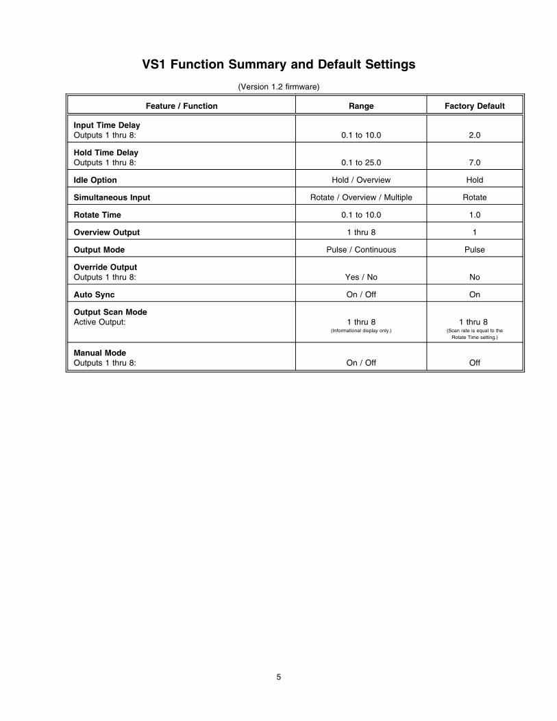
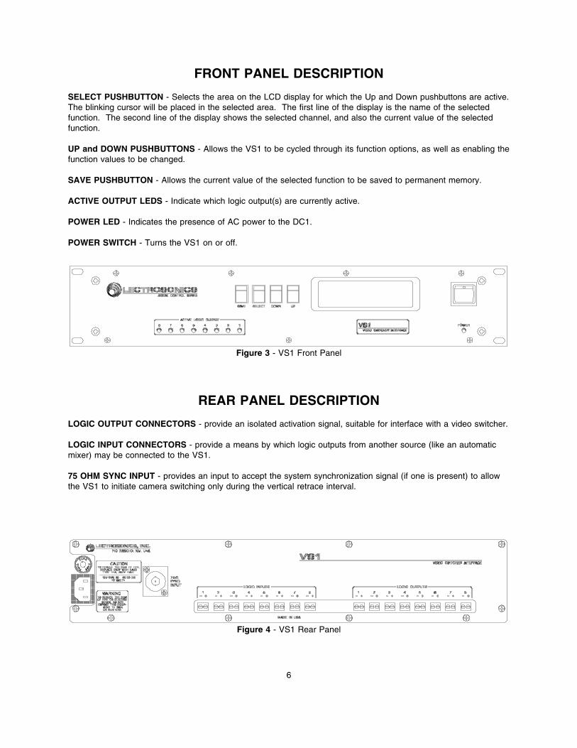
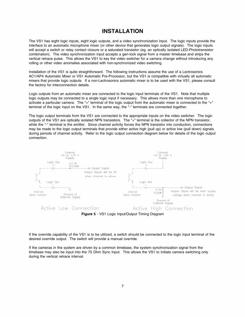
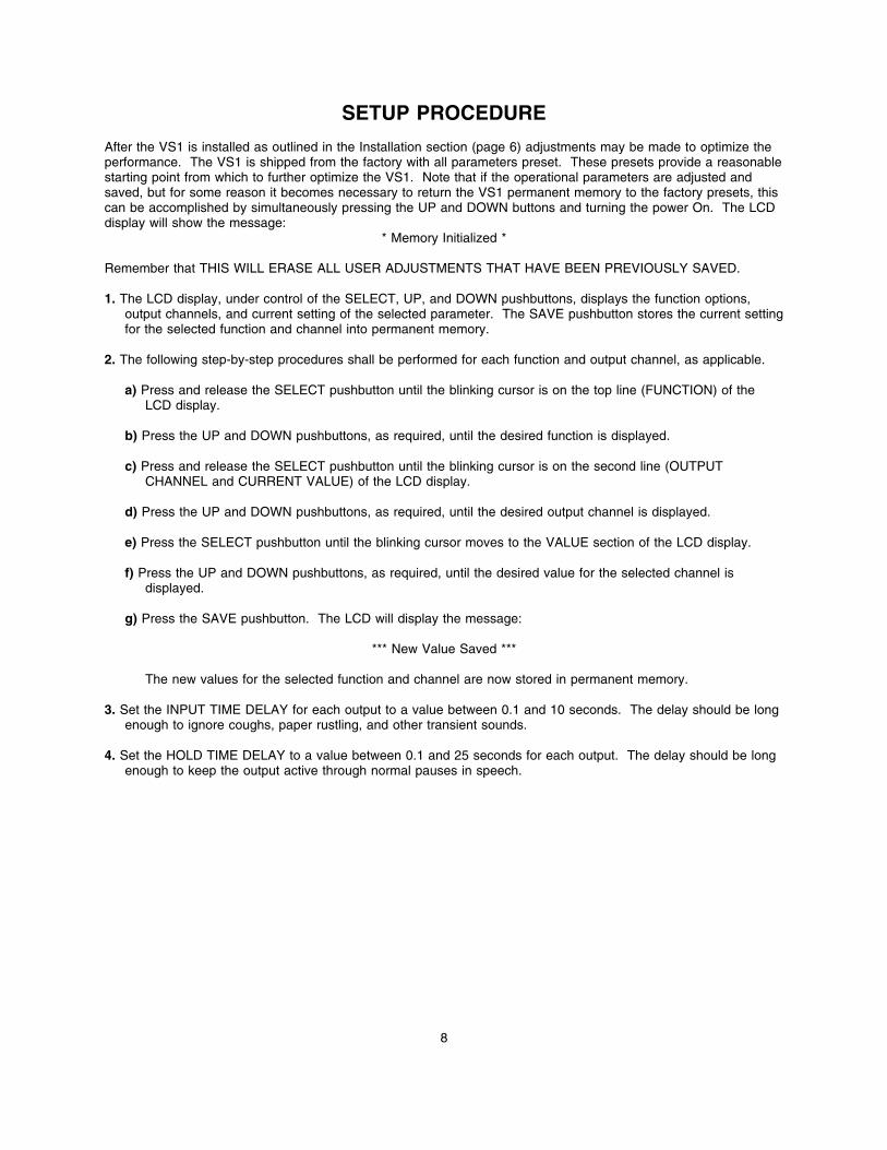
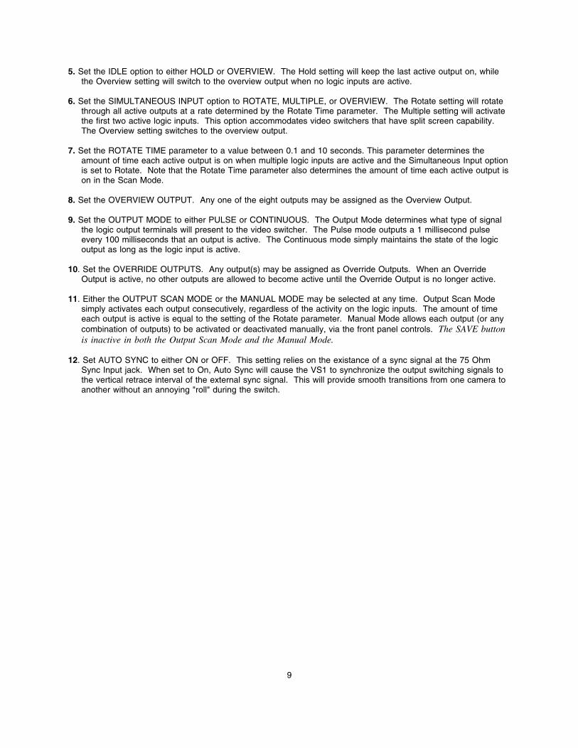
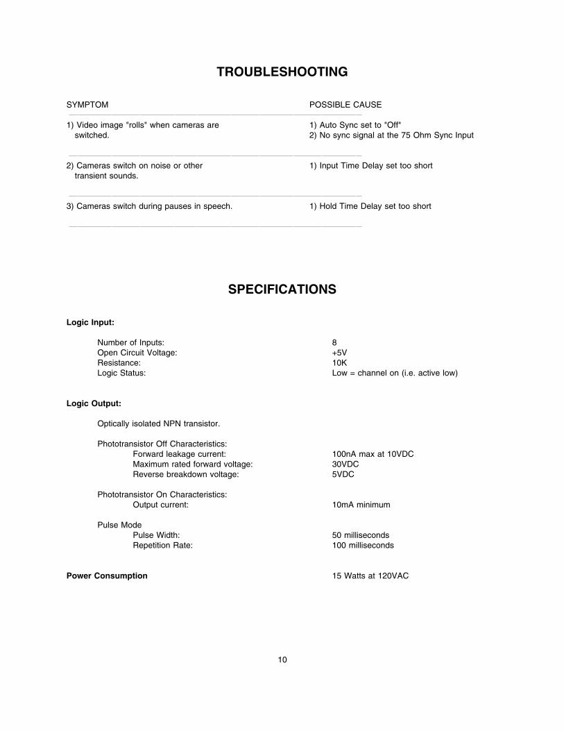
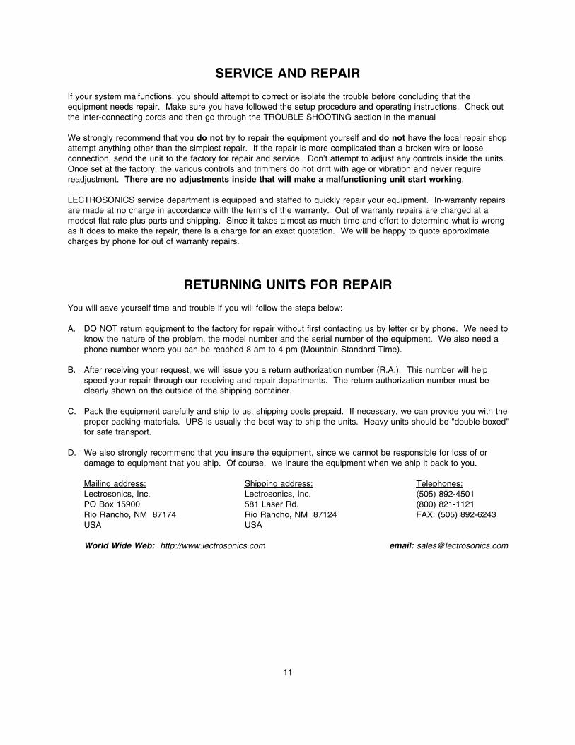