Embed Size (px)
Citation preview
VPMS V2.0 Operation manual
- 1 -
VPMS v2.0 (VoIP PnP Management System)
Operation Manual
AddPac Technology Co., Ltd. 3F, Jeong-Am Bldg., 769-12 Yeoksam-dong
Kangnam-gu Seoul Korea TEL: (02) 568-3848 FAX: (02) 568-3847
E-mail : [email protected] http://www.addpac.com
VPMS V2.0 Operation manual
- 2 -
Contents
1. VPMS (VOIP PLUG & PLAY MANAGEMENT SYSTEM) .................................................................... - 4 -
1.1. INTRODUCTION .........................................................................................................................................- 4 -
1.2. FEATURES..................................................................................................................................................- 4 -
1.3. FUNCTIONS ...............................................................................................................................................- 5 -
1.4. CONFIGURATION DIAGRAM.......................................................................................................................- 6 -
1.5. VPMS PROGRAM SPECIFICATION..............................................................................................................- 7 -
2. VPMS FUNCTION PROCESS.................................................................................................................... - 8 -
2.1. INITIAL SETTING AND SUBSCRIPTION .........................................................................................................- 8 -
2.2. GATEWAY INITIAL SETTING .......................................................................................................................- 9 -
2.3. AUTO-UPGRADE SERVER ........................................................................................................................ - 11 -
3. VPMS INITIAL SCREEN.......................................................................................................................... - 12 -
3.1. GROUP SUMMARY ...................................................................................................................................- 13 -
3.2. STATUS CHART ........................................................................................................................................- 15 -
4. VPMS FUNCTION ..................................................................................................................................... - 17 -
4.1. GROUP MANAGEMENT ............................................................................................................................- 17 -
4.1.1. New Group .................................................................................................................................... - 18 -
4.1.2. Group Modify ................................................................................................................................ - 19 -
4.1.3. Group Delete ................................................................................................................................. - 20 -
4.2. GATEWAY MANAGEMENT ........................................................................................................................- 21 -
4.2.1. New Gateway................................................................................................................................. - 21 -
4.2.2. Modify Gateway ............................................................................................................................ - 24 -
4.2.3. Gateway Delete ............................................................................................................................. - 26 -
4.2.4. login Check.................................................................................................................................... - 27 -
4.2.5. Telnet ............................................................................................................................................. - 29 -
4.3. OPERATOR MANAGEMENT ......................................................................................................................- 32 -
4.3.1. New Operator................................................................................................................................ - 32 -
4.3.2. Operator Modification .................................................................................................................. - 34 -
4.3.3. Operator Delete............................................................................................................................. - 35 -
4.4. MODEL MANAGEMENT ...........................................................................................................................- 36 -
4.4.1. Register Gateway Model ............................................................................................................... - 37 -
4.4.2. Model Modification ....................................................................................................................... - 38 -
4.4.3. Delete Gateway Model .................................................................................................................. - 39 -
4.5. SEARCH...................................................................................................................................................- 40 -
4.5.1. Enter Search Keyword................................................................................................................... - 41 -
4.5.2. Examples of Search Terms............................................................................................................. - 42 -
VPMS V2.0 Operation manual
- 3 -
4.6. OPERATOR DEFINED QUERY....................................................................................................................- 43 -
4.6.1. Define Search Terms...................................................................................................................... - 44 -
4.6.2. Query Deletion .............................................................................................................................. - 46 -
4.7. UPGRADE INFORMATION .........................................................................................................................- 47 -
4.8. EVENT LOG INFORMATION ......................................................................................................................- 48 -
4.9. FTP UPLOAD...........................................................................................................................................- 49 -
4.10. AUTO SCRIPT...........................................................................................................................................- 52 -
4.11. AUXILIARY SCRIPT ..................................................................................................................................- 54 -
4.12. CONFIGURATION .....................................................................................................................................- 56 -
4.13. PRINT ......................................................................................................................................................- 57 -
4.14. GATEWAY STATISTICS..............................................................................................................................- 59 -
5. AN EXAMPLE OF VPMS OPERATION SCENARIO.................................................................... - 62 -
5.1. AN EXAMPLE CONFIGURATION ...............................................................................................................- 62 -
5.2. GROUP A GATEWAY INITIAL SETTING......................................................................................................- 64 -
5.3. GATEWAY GROUP REGISTRATION ............................................................................................................- 66 -
5.4. INPUT GATEWAY INITIAL DATA................................................................................................................- 68 -
5.5. END-CUSTOMER GATEWAY SETTING .......................................................................................................- 70 -
5.6. GATEWAY INFO GENERATION AND INSTALLATION....................................................................................- 70 -
5.7. GROUP A GATEWAY UPGRADE.................................................................................................................- 73 -
5.7.1. Auto script upgrade ....................................................................................................................... - 73 -
5.7.2. APOS Image upgrade.................................................................................................................... - 76 -
VPMS V2.0 Operation manual
- 4 -
1. VPMS (VoIP Plug & Play Management System)
1.1. Introduction
To install VoIP Gateway, the installation experts are asked to visit the place of installation and it is not
economical and also time consuming. To overcome such shortcomings, Gateway default configuration,
automatic Firmware upgrade and debugging are made possible with VPMS (VoIP Plug & Play
Management System).
1.2. Features
▪ Without installation experts or additional installers, VPMS makes possible initial setting of remote VoIP
Gateway according to customers’ service requests.
▪ VPMS (VoIP Plug & Play Management System) offers automatic initial configuration and real-time
monitoring of gateway. Also, easy and convenient Firmware binary file and configuration change are
possible via GUI (Graphic User Interface).
▪ VPMS operators can check real time condition of remote VoIP gateway as a graph and a table. So,
easy monitoring and quick actions are possible.
▪ VPMS offers Firmware binary file and configuration change of a group or an individual VoIP gateway
reducing operator’s workload. Also, by keeping configuration change history, VPMS clearly shows the
list of configuration changes.
▪ Without additional programs, built-in Telnet and FTP programs are offered. Also, automatic login is
supported without knowing Telnet or Ftp ID and Password of each VoIP Gateway.
VPMS V2.0 Operation manual
- 5 -
1.3. Functions
▪ Automatic initial setting
Without installation experts or additional installers, VPMS makes possible initial setting of remote VoIP
Gateway depend on customers’ service requests.
▪ Gateway monitoring
VPMS operators can easily monitor the registered Gateway via GUI.
▪ Automatic upgrade
VPMS operator conducts File upload and auto-script via GUI with VPMS program by using existing
Auto-upgrade (auto upgrade server) function, which makes possible Firmware binary file and
configuration change. Also, configuration changes can be searched.
▪ CLI
With built-in Telnet, VPMS automatically accesses to a specific Gateway and conducts configuration
change.
▪ Gateway management
VPMS offers Gateway management (registration, modification, inquiry, deletion, search).
▪ Operator management
VPMS offers VPMS operator account management (registration, modification, inquiry, deletion, search).
Also, by offering various operator levels, certain VPMS functions can be regulated.
▪ VoIP group management
VoIP management can be done by groups. So registration, modification, inquiry and deletion of
gateway groups are possible.
▪ Event log view
VPMS displays Event log of gateways such as initial setting (Only allowed for Admin Users).
▪ Gateway condition statistics
VPMS supports Status Chart function displaying the real-time condition of gateway. Also, the
statistical information can be saved and searched by the time.
VPMS V2.0 Operation manual
- 6 -
1.4. Configuration Diagram
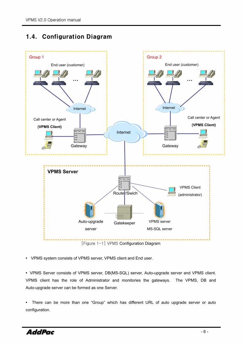
[Figure 1-1] VPMS Configuration Diagram
▪ VPMS system consists of VPMS server, VPMS client and End user.
▪ VPMS Server consists of VPMS server, DB(MS-SQL) server, Auto-upgrade server and VPMS client.
VPMS client has the role of Administrator and monitories the gateways. The VPMS, DB and
Auto-upgrade server can be formed as one Server.
▪ There can be more than one “Group” which has different URL of auto upgrade server or auto
configuration.
VPMS Server
Group 2
Gateway Gateway
Gatekeeper
Group 1
Router/Swich
Auto-upgrade
server
VPMS server
MS-SQL server
Call center or Agent
(VPMS Client)
VPMS Client
(administrator)
Internet
Internet
… …
End user (customer) End user (customer)
Call center or Agent
(VPMS Client)
Internet
VPMS V2.0 Operation manual
- 7 -
1.5. VPMS Program Specification
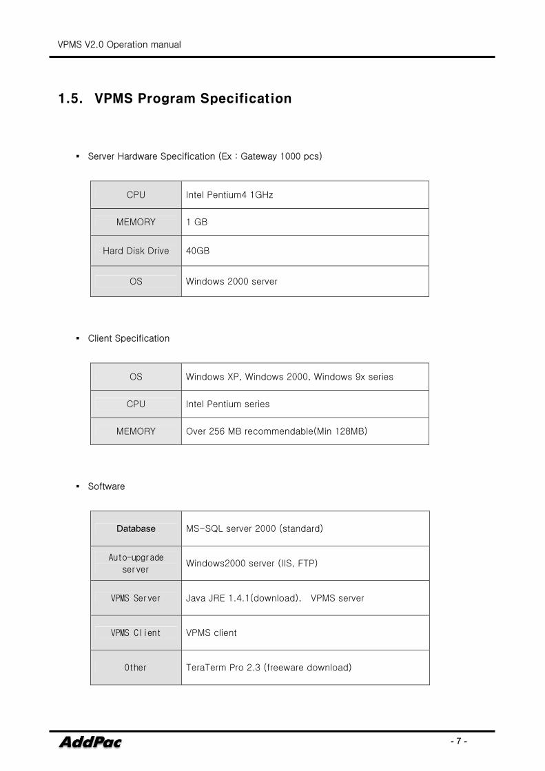
▪ Server Hardware Specification (Ex : Gateway 1000 pcs)
CPU Intel Pentium4 1GHz
MEMORY 1 GB
Hard Disk Drive 40GB
OS Windows 2000 server
▪ Client Specification
OS Windows XP, Windows 2000, Windows 9x series
CPU Intel Pentium series
MEMORY Over 256 MB recommendable(Min 128MB)
▪ Software
Database MS-SQL server 2000 (standard)
Auto-upgrade
server Windows2000 server (IIS, FTP)
VPMS Server Java JRE 1.4.1(download), VPMS server
VPMS Client VPMS client
Other TeraTerm Pro 2.3 (freeware download)
VPMS V2.0 Operation manual
- 8 -
2. VPMS Function process
2.1. Initial setting and subscription
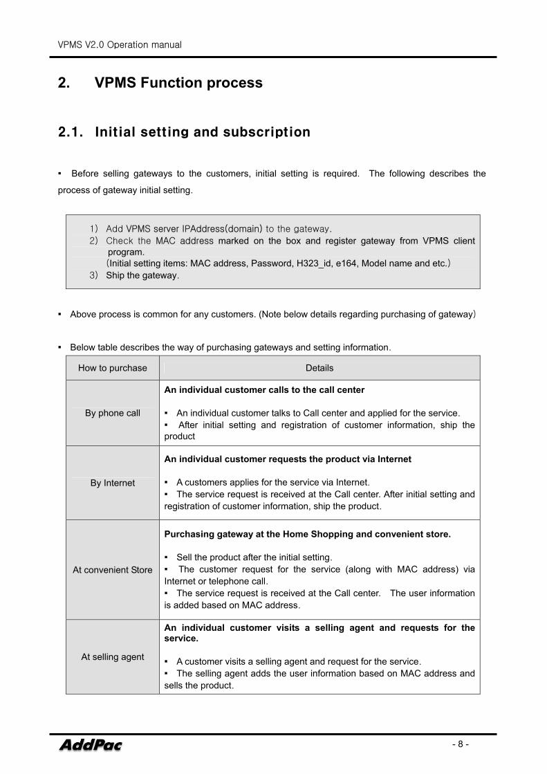
▪ Before selling gateways to the customers, initial setting is required. The following describes the
process of gateway initial setting.
1) Add VPMS server IPAddress(domain) to the gateway.
2) Check the MAC address marked on the box and register gateway from VPMS client program. (Initial setting items: MAC address, Password, H323_id, e164, Model name and etc.)
3) Ship the gateway.
▪ Above process is common for any customers. (Note below details regarding purchasing of gateway)
▪ Below table describes the way of purchasing gateways and setting information.
How to purchase Details
By phone call
An individual customer calls to the call center
▪ An individual customer talks to Call center and applied for the service.
▪ After initial setting and registration of customer information, ship the product
By Internet
An individual customer requests the product via Internet
▪ A customers applies for the service via Internet. ▪ The service request is received at the Call center. After initial setting and registration of customer information, ship the product.
At convenient Store
Purchasing gateway at the Home Shopping and convenient store.
▪ Sell the product after the initial setting.
▪ The customer request for the service (along with MAC address) via Internet or telephone call. ▪ The service request is received at the Call center. The user information is added based on MAC address.
At selling agent
An individual customer visits a selling agent and requests for the service.
▪ A customer visits a selling agent and request for the service.
▪ The selling agent adds the user information based on MAC address and sells the product.
VPMS V2.0 Operation manual
- 9 -
2.2. Gateway Initial Setting
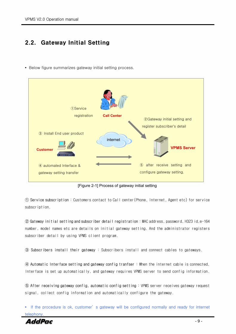
▪ Below figure summarizes gateway initial setting process.
[Figure 2-1] Process of gateway initial setting
① Service subscription : Customers contact to Call center(Phone, Internet, Agent etc) for service
subscription.
② Gateway initial setting and subscriber detail registration : MAC address, password, H323 id,e-164
number, model names etc are details on initial gateway setting. And the administrator registers
subscriber detail by using VPMS client program.
③ Subscribers install their gateway : Subscribers install and connect cables to gateways.
④ Automatic Interface setting and gateway config tranfser : When the internet cable is connected,
Interface is set up automatically, and gateway requires VPMS server to send config information.
⑤ After receiving gateway config, automatic config setting : VPMS server receives gateway request
signal, collect config information and automatically configure the gateway.
▪ If the procedure is ok, customer’ s gateway will be configured normally and ready for internet
telephony.
①Service
registration ②Gateway initial setting and
register subscriber’s detail
③ Install End user product
internet
④ automated Interface &
gateway setting transfer
⑤ after receive setting and
configure gateway setting.
Call Center
Customer VPMS Server

VPMS V2.0 Operation manual
- 10 -
VPMS V2.0 Operation manual
- 11 -
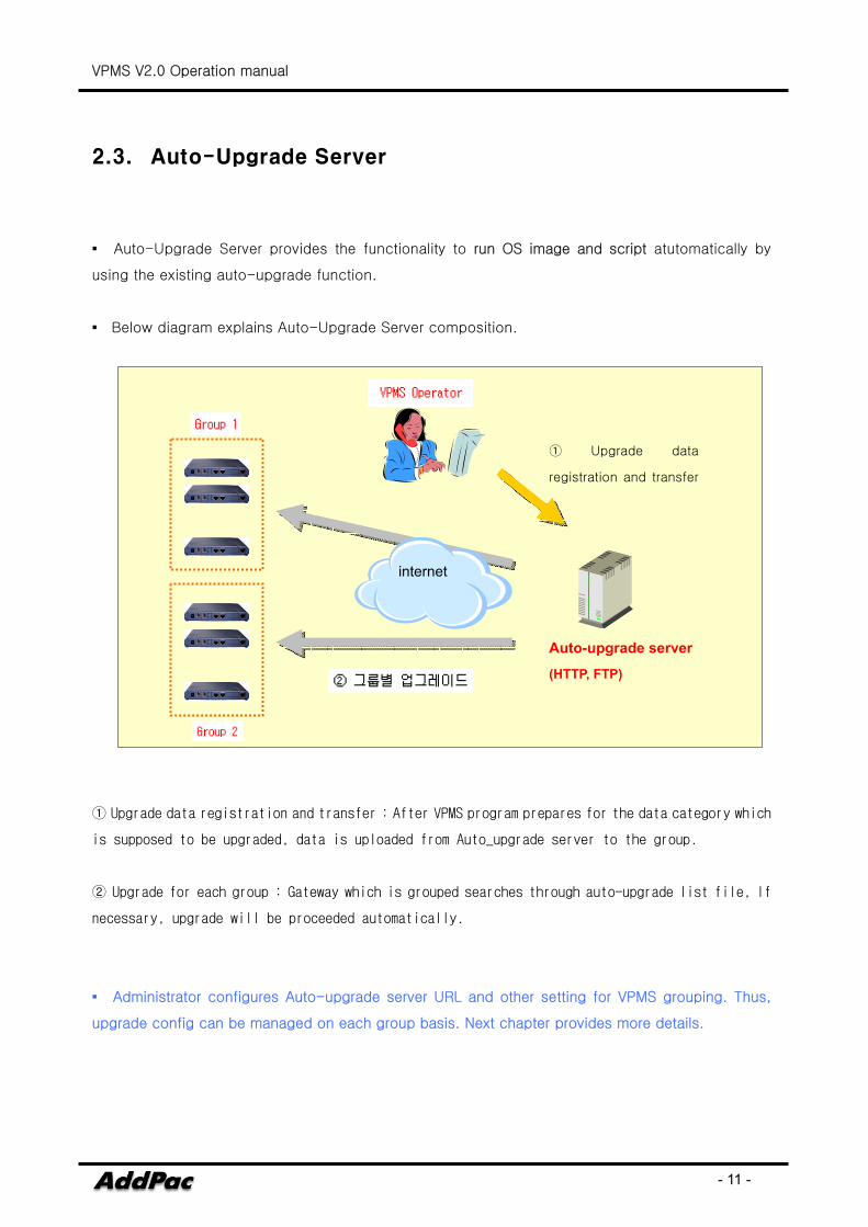
2.3. Auto-Upgrade Server
▪ Auto-Upgrade Server provides the functionality to run OS image and script atutomatically by
using the existing auto-upgrade function.
▪ Below diagram explains Auto-Upgrade Server composition.
① Upgrade data registration and transfer : After VPMS program prepares for the data category which
is supposed to be upgraded, data is uploaded from Auto_upgrade server to the group.
② Upgrade for each group : Gateway which is grouped searches through auto-upgrade list file, If
necessary, upgrade will be proceeded automatically.
▪ Administrator configures Auto-upgrade server URL and other setting for VPMS grouping. Thus,
upgrade config can be managed on each group basis. Next chapter provides more details.
internet
① Upgrade data
registration and transfer
Auto-upgrade server
(HTTP, FTP)
VPMS V2.0 Operation manual
- 12 -
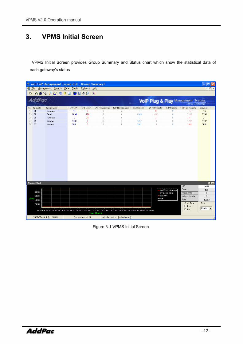
3. VPMS Initial Screen
VPMS Initial Screen provides Group Summary and Status chart which show the statistical data of
each gateway’s status.
Figure 3-1 VPMS Initial Screen
VPMS V2.0 Operation manual
- 13 -
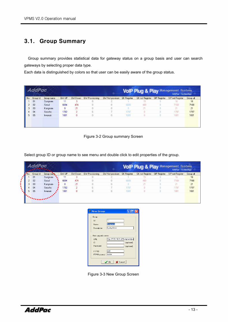
3.1. Group Summary
Group summary provides statistical data for gateway status on a group basis and user can search
gateways by selecting proper data type.
Each data is distinguished by colors so that user can be easily aware of the group status.
Figure 3-2 Group summary Screen
Select group ID or group name to see menu and double click to edit properties of the group.
Figure 3-3 New Group Screen
VPMS V2.0 Operation manual
- 14 -
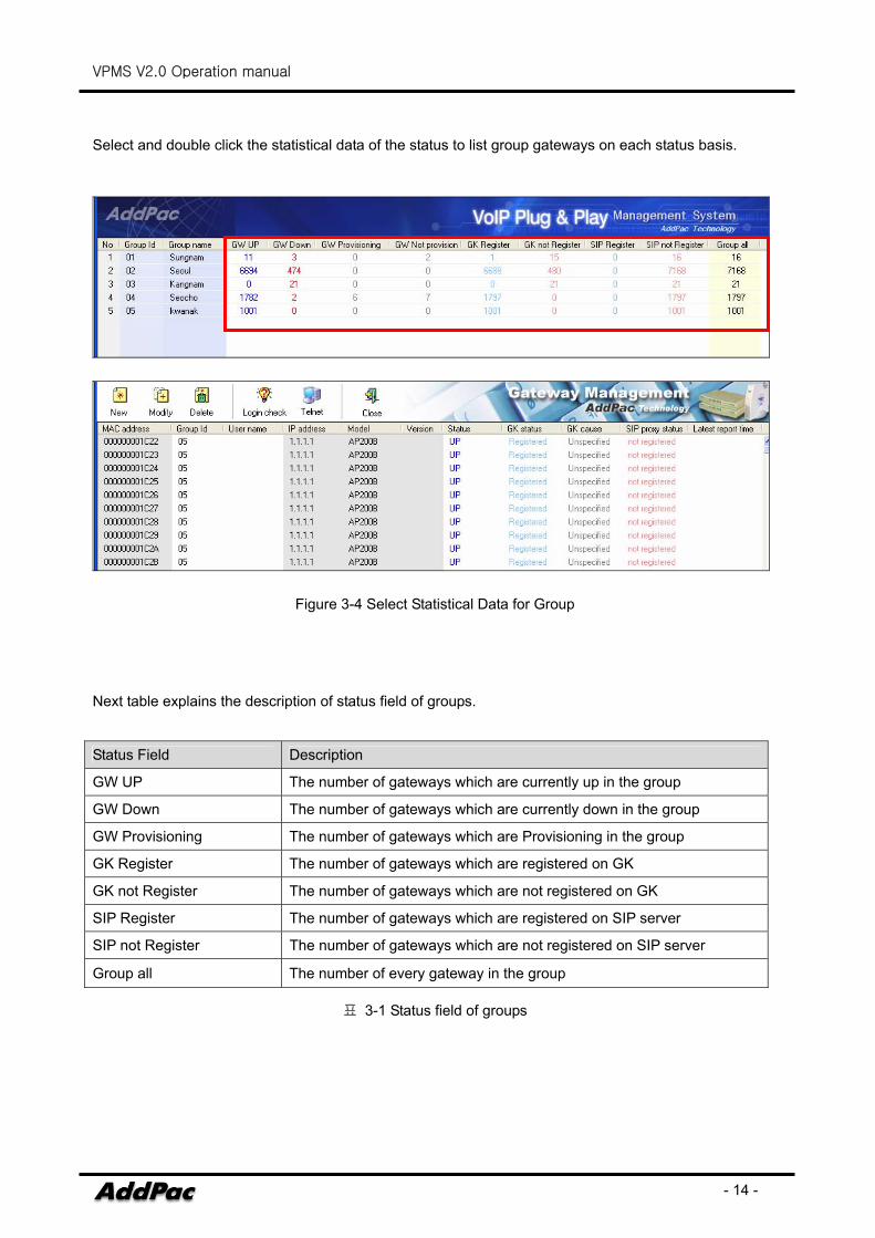
Select and double click the statistical data of the status to list group gateways on each status basis.
Figure 3-4 Select Statistical Data for Group
Next table explains the description of status field of groups.
Status Field Description
GW UP The number of gateways which are currently up in the group
GW Down The number of gateways which are currently down in the group
GW Provisioning The number of gateways which are Provisioning in the group
GK Register The number of gateways which are registered on GK
GK not Register The number of gateways which are not registered on GK
SIP Register The number of gateways which are registered on SIP server
SIP not Register The number of gateways which are not registered on SIP server
Group all The number of every gateway in the group
표 3-1 Status field of groups
VPMS V2.0 Operation manual
- 15 -
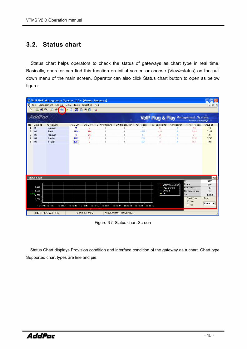
3.2. Status chart
Status chart helps operators to check the status of gateways as chart type in real time. Basically, operator can find this function on initial screen or choose (View>status) on the pull down menu of the main screen. Operator can also click Status chart button to open as below figure.
Figure 3-5 Status chart Screen
Status Chart displays Provision condition and interface condition of the gateway as a chart. Chart type
Supported chart types are line and pie.
VPMS V2.0 Operation manual
- 16 -
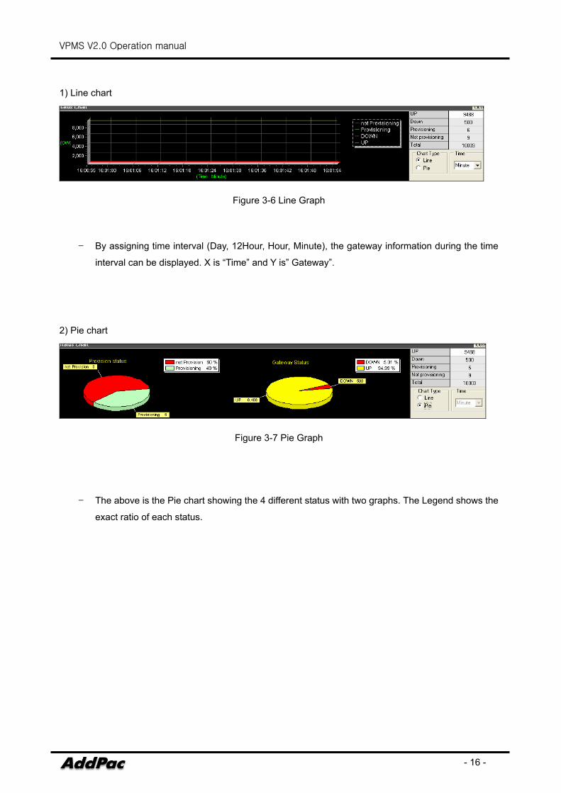
1) Line chart
Figure 3-6 Line Graph
- By assigning time interval (Day, 12Hour, Hour, Minute), the gateway information during the time
interval can be displayed. X is “Time” and Y is” Gateway”.
2) Pie chart
Figure 3-7 Pie Graph
- The above is the Pie chart showing the 4 different status with two graphs. The Legend shows the
exact ratio of each status.
VPMS V2.0 Operation manual
- 17 -
4. VPMS Function
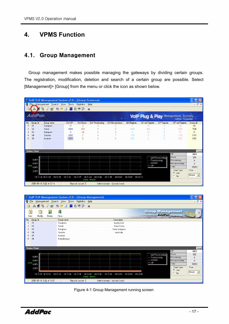
4.1. Group Management
Group management makes possible managing the gateways by dividing certain groups. The registration, modification, deletion and search of a certain group are possible. Select [Management]> [Group] from the menu or click the icon as shown below.
Figure 4-1 Group Management running screen
VPMS V2.0 Operation manual
- 18 -
♦ Group management can be only accessed by Administrator account. .
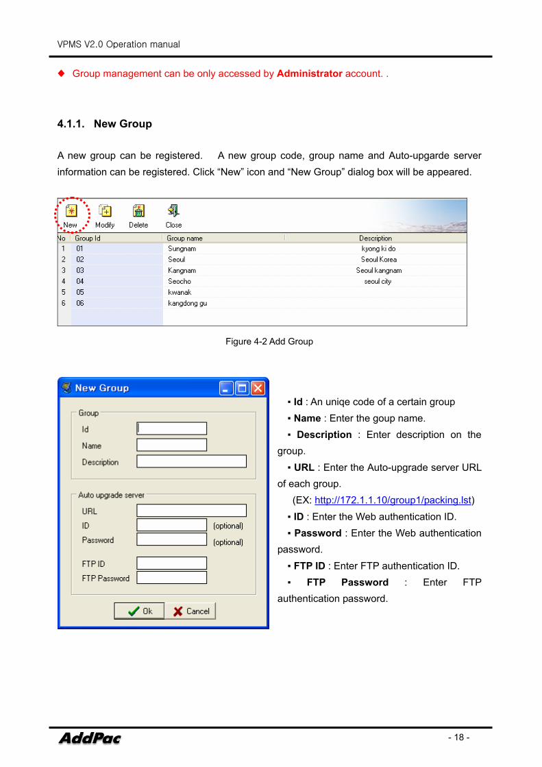
4.1.1. New Group A new group can be registered. A new group code, group name and Auto-upgarde server information can be registered. Click “New” icon and “New Group” dialog box will be appeared.
Figure 4-2 Add Group
▪ Id : An uniqe code of a certain group ▪ Name : Enter the goup name. ▪ Description : Enter description on the
group. ▪ URL : Enter the Auto-upgrade server URL
of each group. (EX: http://172.1.1.10/group1/packing.lst) ▪ ID : Enter the Web authentication ID. ▪ Password : Enter the Web authentication
password. ▪ FTP ID : Enter FTP authentication ID. ▪ FTP Password : Enter FTP
authentication password.
VPMS V2.0 Operation manual
- 19 -
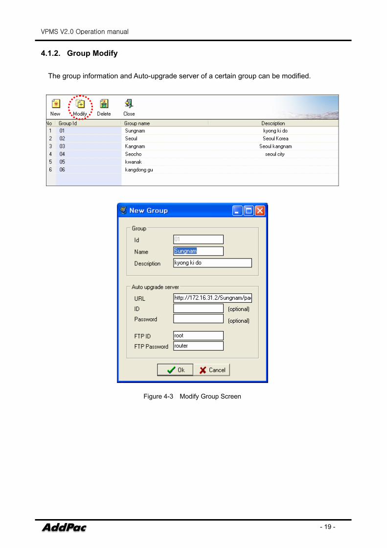
4.1.2. Group Modify
The group information and Auto-upgrade server of a certain group can be modified.
Figure 4-3 Modify Group Screen
VPMS V2.0 Operation manual
- 20 -
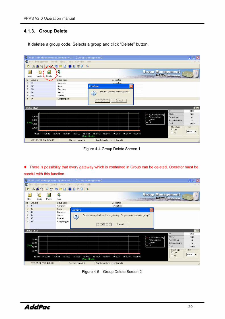
4.1.3. Group Delete
It deletes a group code. Selects a group and click “Delete” button.
Figure 4-4 Group Delete Screen 1
♦ There is possibility that every gateway which is contained in Group can be deleted. Operator must be
careful with this function.
Figure 4-5 Group Delete Screen 2
VPMS V2.0 Operation manual
- 21 -
4.2. Gateway management
Gateway management offers registration, modification, deletion and search of gateway users. ♦ User can enter each group’s gateway management screen is provided by Group summary.
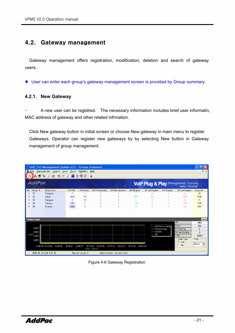
4.2.1. New Gateway
- A new user can be registred. The necessary information includes brief user informatin, MAC address of gateway and other related infrmation.
Click New gateway button in initial screen or choose New gateway in main menu to register Gateways. Operator can register new gateways by by selecting New button in Gateway management of group management.
Figure 4-6 Gateway Registration
VPMS V2.0 Operation manual
- 22 -
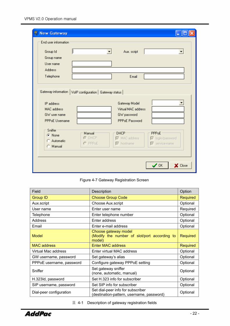
Figure 4-7 Gateway Registration Screen
Field Description Option Group ID Choose Group Code RequiredAux.script Choose Aux.script Optional User name Enter user name RequiredTelephone Enter telephone number Optional Address Enter address Optional Email Enter e-mail address Optional
Model Choose gateway model (Modify the number of slot/port according to model)
Required
MAC address Enter MAC address RequiredVirtual Mac address Enter virtual MAC address Optional GW username, password Set gateway’s alias Optional PPPoE username, password Configure gateway PPPoE setting Optional
Sniffer Set gateway sniffer (none, automatic, manual) Optional
H.323Id, password Set H.323 info for subscriber Optional SIP username, password Set SIP info for subscriber Optional
Dial-peer configuration Set dial-peer info for subscriber (destination-pattern, username, password) Optional
표 4-1 Description of gateway registration fields

VPMS V2.0 Operation manual
- 23 -
VPMS V2.0 Operation manual
- 24 -
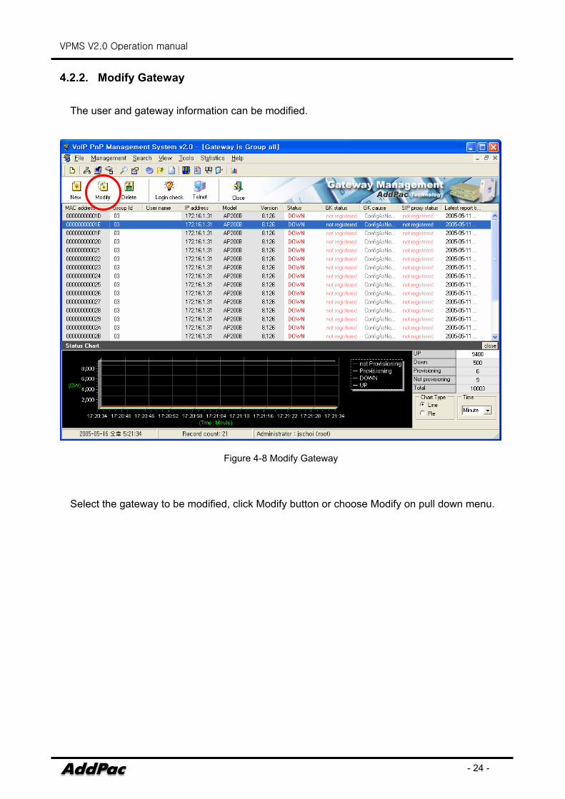
4.2.2. Modify Gateway
The user and gateway information can be modified.
Figure 4-8 Modify Gateway
Select the gateway to be modified, click Modify button or choose Modify on pull down menu.
VPMS V2.0 Operation manual
- 25 -
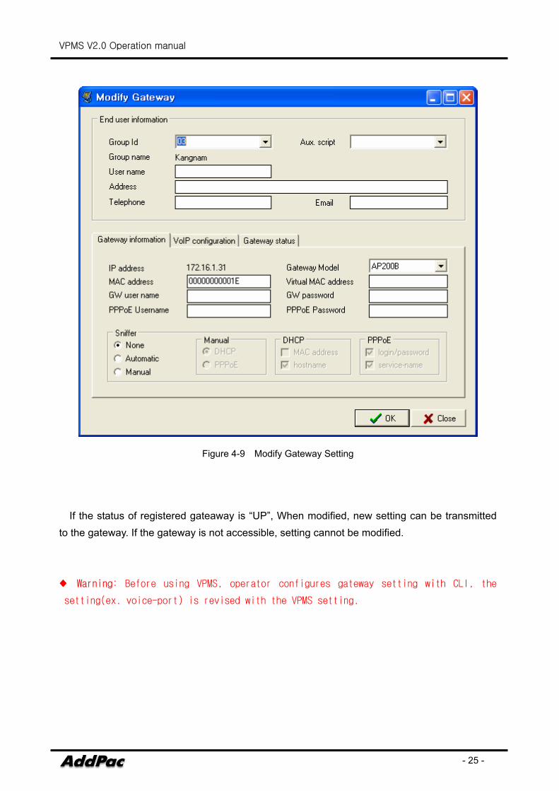
Figure 4-9 Modify Gateway Setting
If the status of registered gateaway is “UP”, When modified, new setting can be transmitted to the gateway. If the gateway is not accessible, setting cannot be modified. ♦ Warning: Before using VPMS, operator configures gateway setting with CLI, the
setting(ex. voice-port) is revised with the VPMS setting.
VPMS V2.0 Operation manual
- 26 -
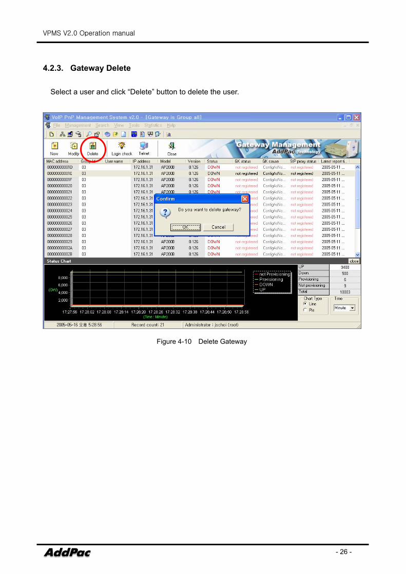
4.2.3. Gateway Delete
Select a user and click “Delete” button to delete the user.
Figure 4-10 Delete Gateway
VPMS V2.0 Operation manual
- 27 -
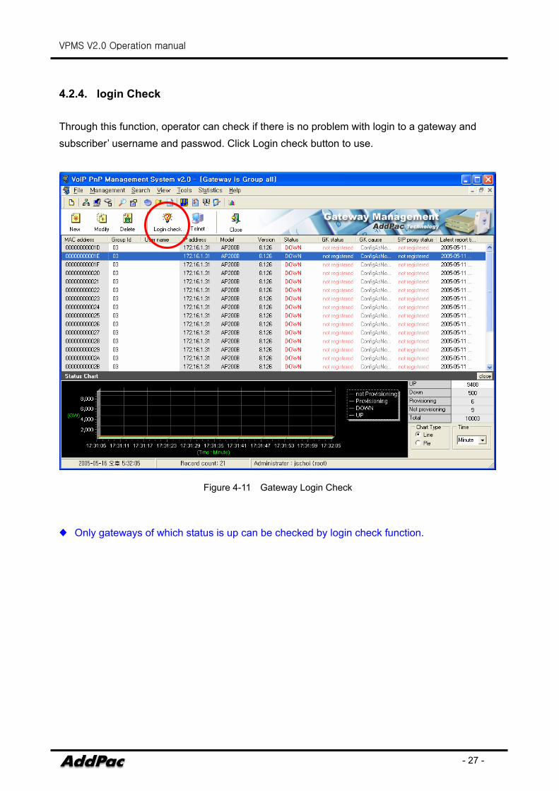
4.2.4. login Check Through this function, operator can check if there is no problem with login to a gateway and subscriber’ username and passwod. Click Login check button to use.
Figure 4-11 Gateway Login Check
♦ Only gateways of which status is up can be checked by login check function.
VPMS V2.0 Operation manual
- 28 -
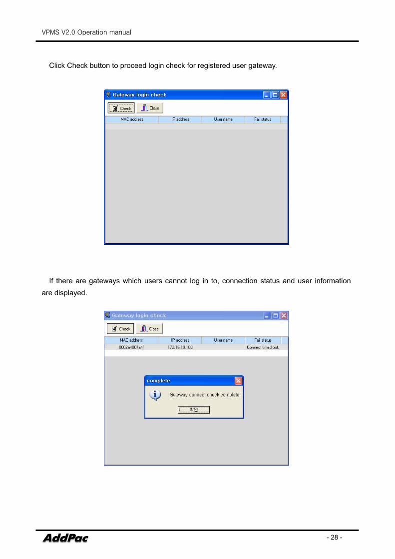
Click Check button to proceed login check for registered user gateway.
If there are gateways which users cannot log in to, connection status and user information are displayed.
VPMS V2.0 Operation manual
- 29 -
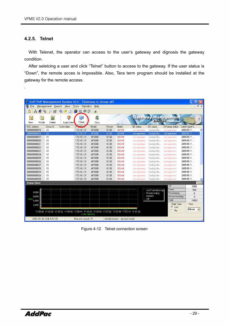
4.2.5. Telnet
With Telenet, the operator can access to the user’s gateway and dignosis the gateway condition.
After seletcing a user and click “Telnet” button to access to the gateway. If the user status is “Down”, the remote acces is impossible. Also, Tera term program should be installed at the gateway for the remote access. .
Figure 4-12 Telnet connection screen
VPMS V2.0 Operation manual
- 30 -
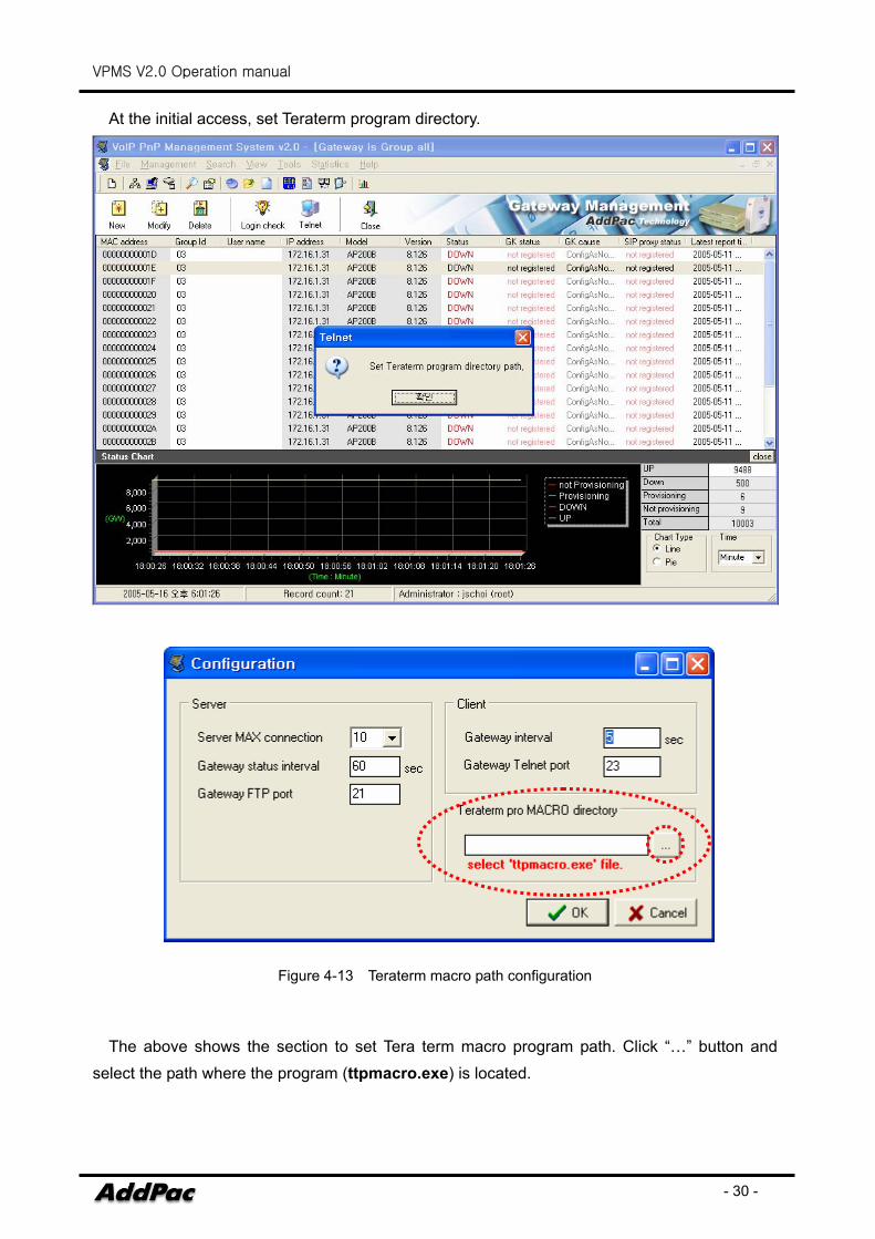
At the initial access, set Teraterm program directory.
Figure 4-13 Teraterm macro path configuration
The above shows the section to set Tera term macro program path. Click “…” button and
select the path where the program (ttpmacro.exe) is located.
VPMS V2.0 Operation manual
- 31 -
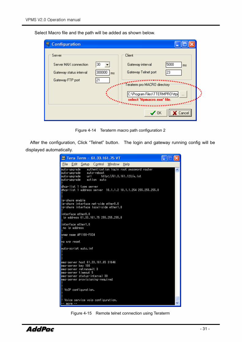
Select Macro file and the path will be added as shown below.
Figure 4-14 Teraterm macro path configuration 2
After the configuration, Click “Telnet” button. The login and gateway running config will be displayed automatically.
Figure 4-15 Remote telnet connection using Teraterm
VPMS V2.0 Operation manual
- 32 -
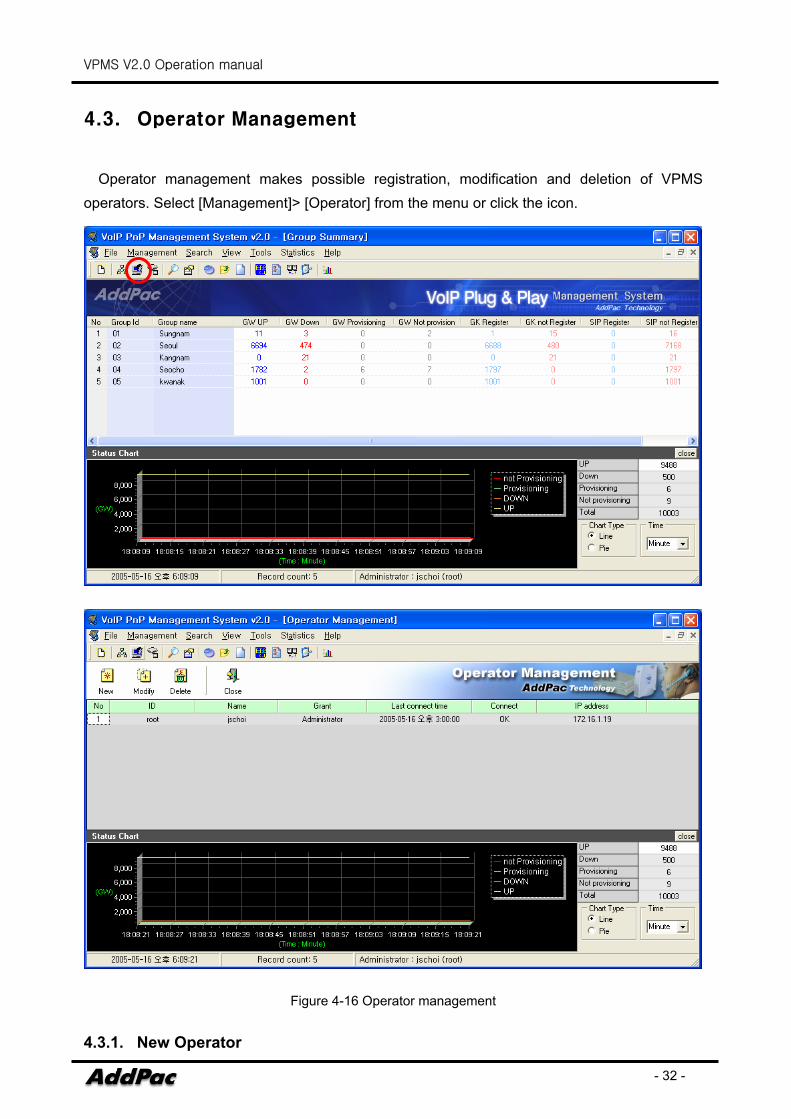
4.3. Operator Management
Operator management makes possible registration, modification and deletion of VPMS operators. Select [Management]> [Operator] from the menu or click the icon.
Figure 4-16 Operator management
4.3.1. New Operator
VPMS V2.0 Operation manual
- 33 -
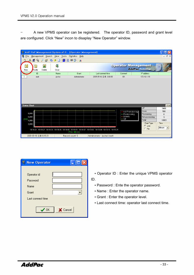
- A new VPMS operator can be registered. The operator ID, password and grant level are configured. Click “New” incon to disaplay “New Operator” window.
▪ Operator ID : Enter the unique VPMS operator
ID. ▪ Password : Ente the operator password. ▪ Name : Enter the operator name. ▪ Grant : Enter the operator level. ▪ Last connect time: operator last connect time.
VPMS V2.0 Operation manual
- 34 -
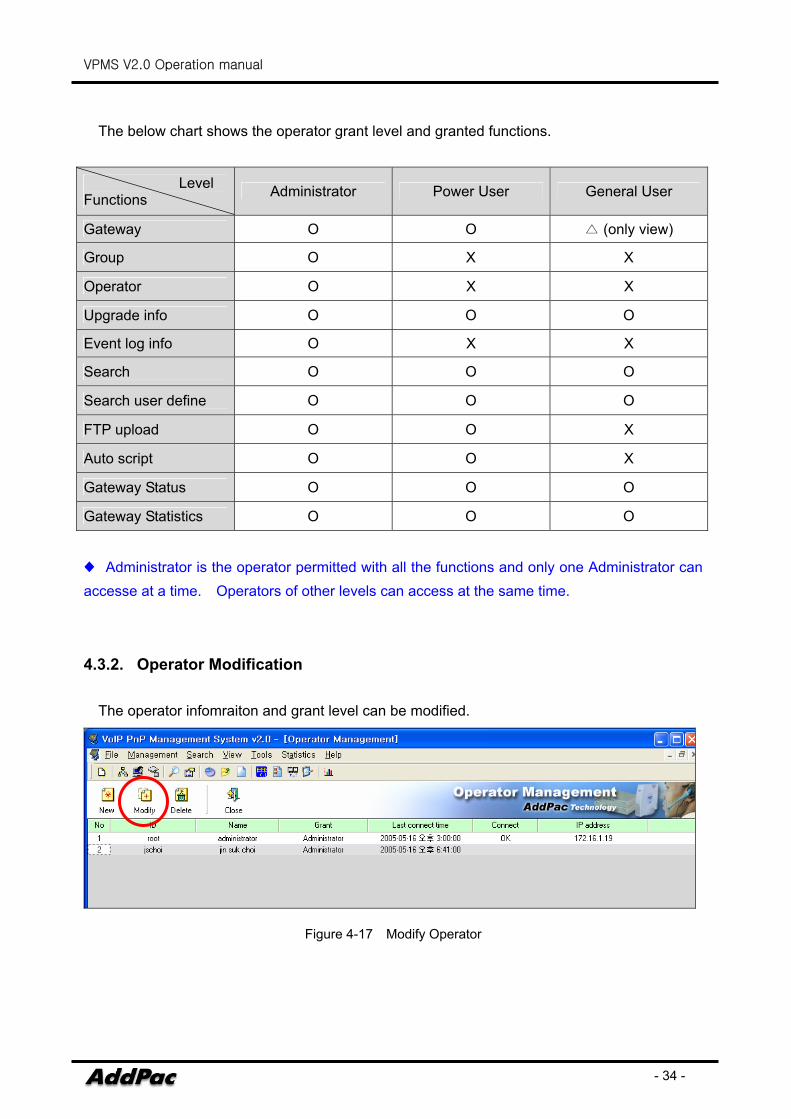
The below chart shows the operator grant level and granted functions.
Level Functions Administrator Power User General User
Gateway O O △ (only view)
Group O X X
Operator O X X
Upgrade info O O O
Event log info O X X
Search O O O
Search user define O O O
FTP upload O O X
Auto script O O X
Gateway Status O O O
Gateway Statistics O O O
♦ Administrator is the operator permitted with all the functions and only one Administrator can accesse at a time. Operators of other levels can access at the same time.
4.3.2. Operator Modification
The operator infomraiton and grant level can be modified.
Figure 4-17 Modify Operator
VPMS V2.0 Operation manual
- 35 -
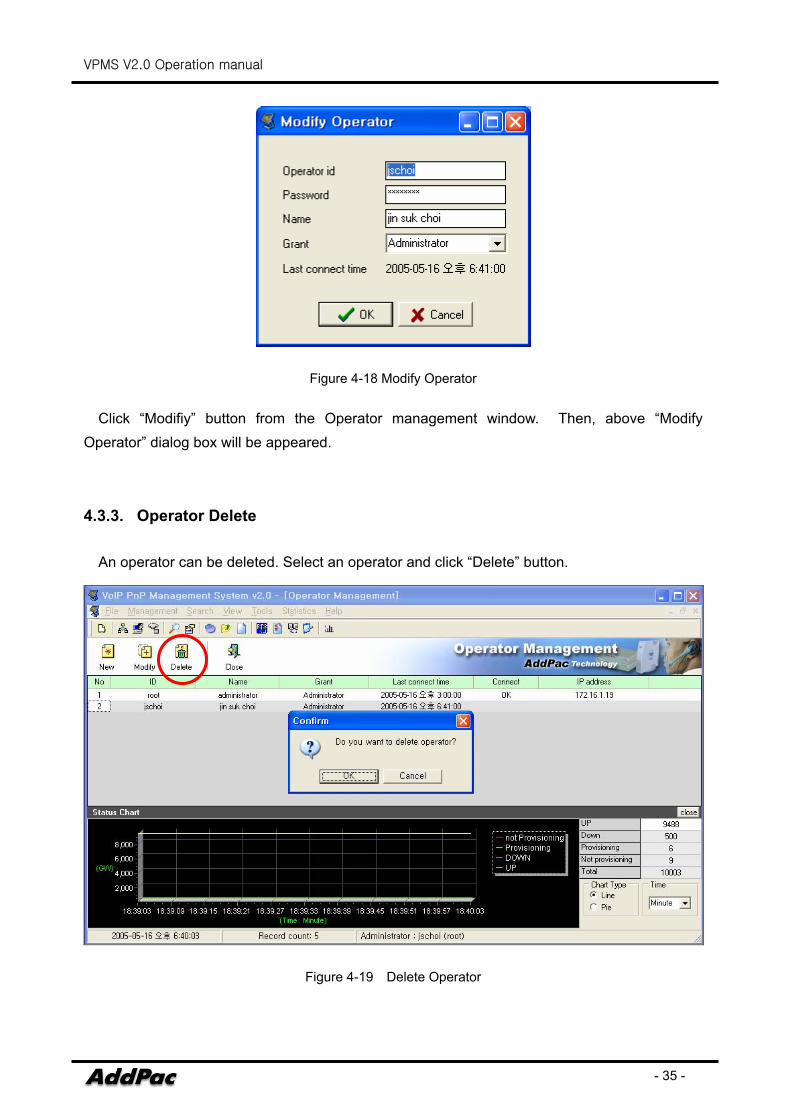
Figure 4-18 Modify Operator
Click “Modifiy” button from the Operator management window. Then, above “Modify Operator” dialog box will be appeared.
4.3.3. Operator Delete
An operator can be deleted. Select an operator and click “Delete” button.
Figure 4-19 Delete Operator
VPMS V2.0 Operation manual
- 36 -
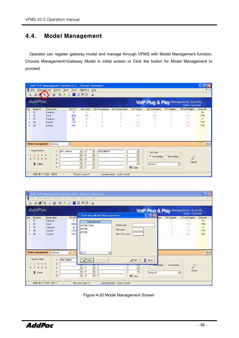
4.4. Model Management
Operator can register gateway model and manage through VPMS with Model Management function.
Choose Management>Gateway Model in initial screen or Click the button for Model Management to
proceed.
Figure 4-20 Model Management Screen
VPMS V2.0 Operation manual
- 37 -
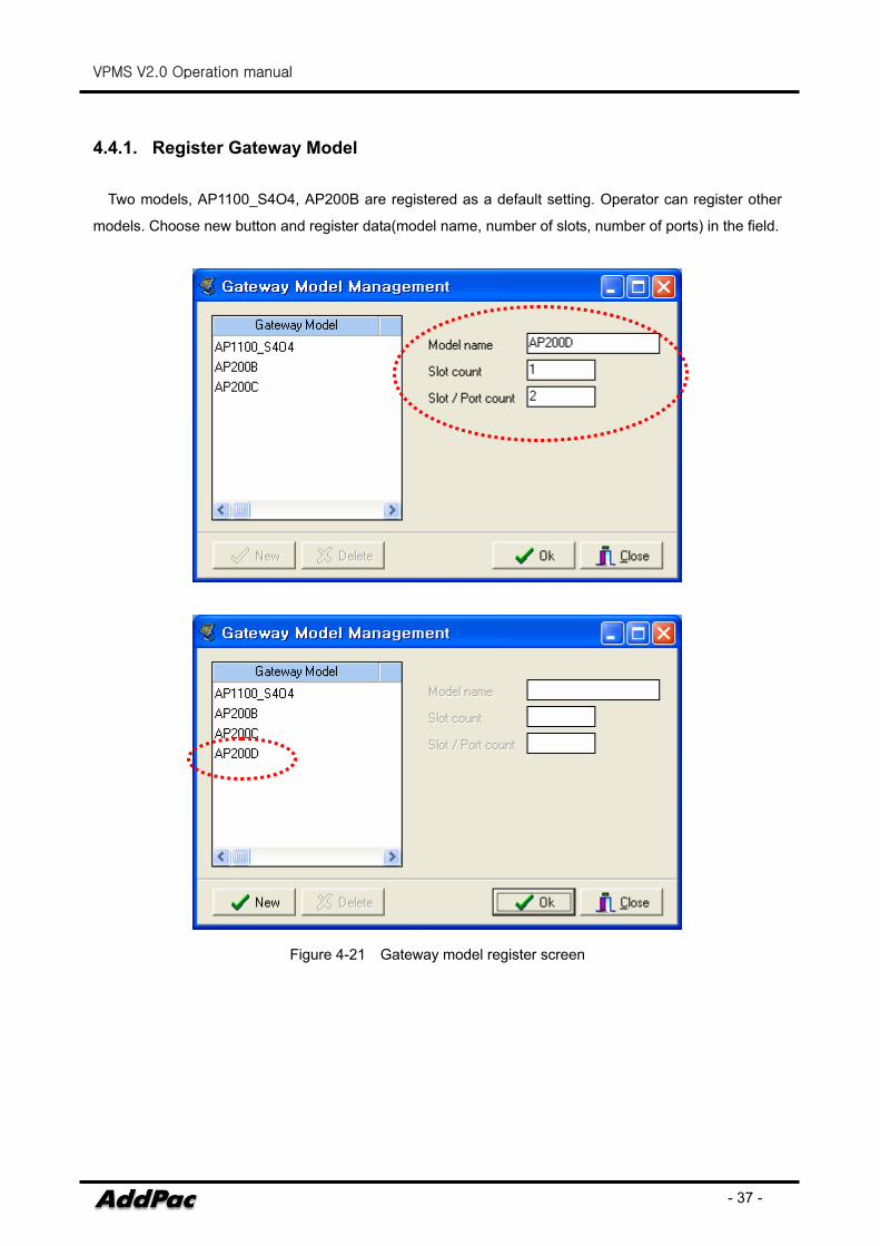
4.4.1. Register Gateway Model
Two models, AP1100_S4O4, AP200B are registered as a default setting. Operator can register other
models. Choose new button and register data(model name, number of slots, number of ports) in the field.
Figure 4-21 Gateway model register screen
VPMS V2.0 Operation manual
- 38 -
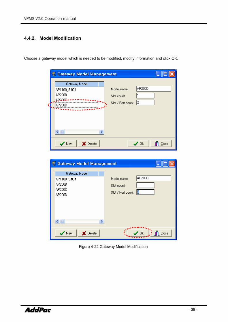
4.4.2. Model Modification
Choose a gateway model which is needed to be modified, modify information and click OK.
Figure 4-22 Gateway Model Modification
VPMS V2.0 Operation manual
- 39 -
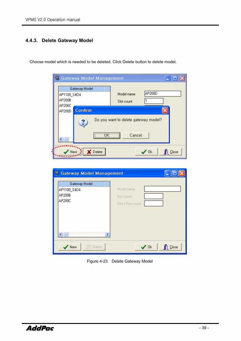
4.4.3. Delete Gateway Model
Choose model which is needed to be deleted. Click Delete button to delete model.
Figure 4-23 Delete Gateway Model
VPMS V2.0 Operation manual
- 40 -
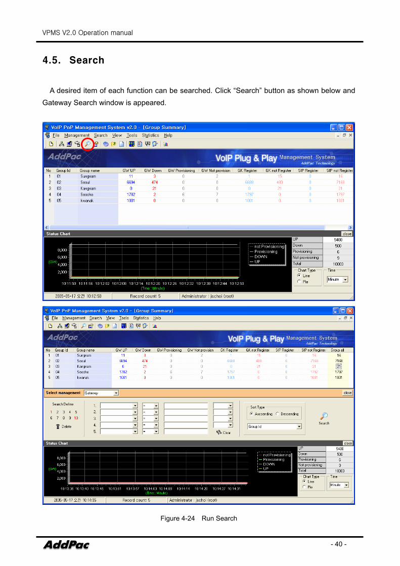
4.5. Search
A desired item of each function can be searched. Click “Search” button as shown below and Gateway Search window is appeared.
Figure 4-24 Run Search
VPMS V2.0 Operation manual
- 41 -
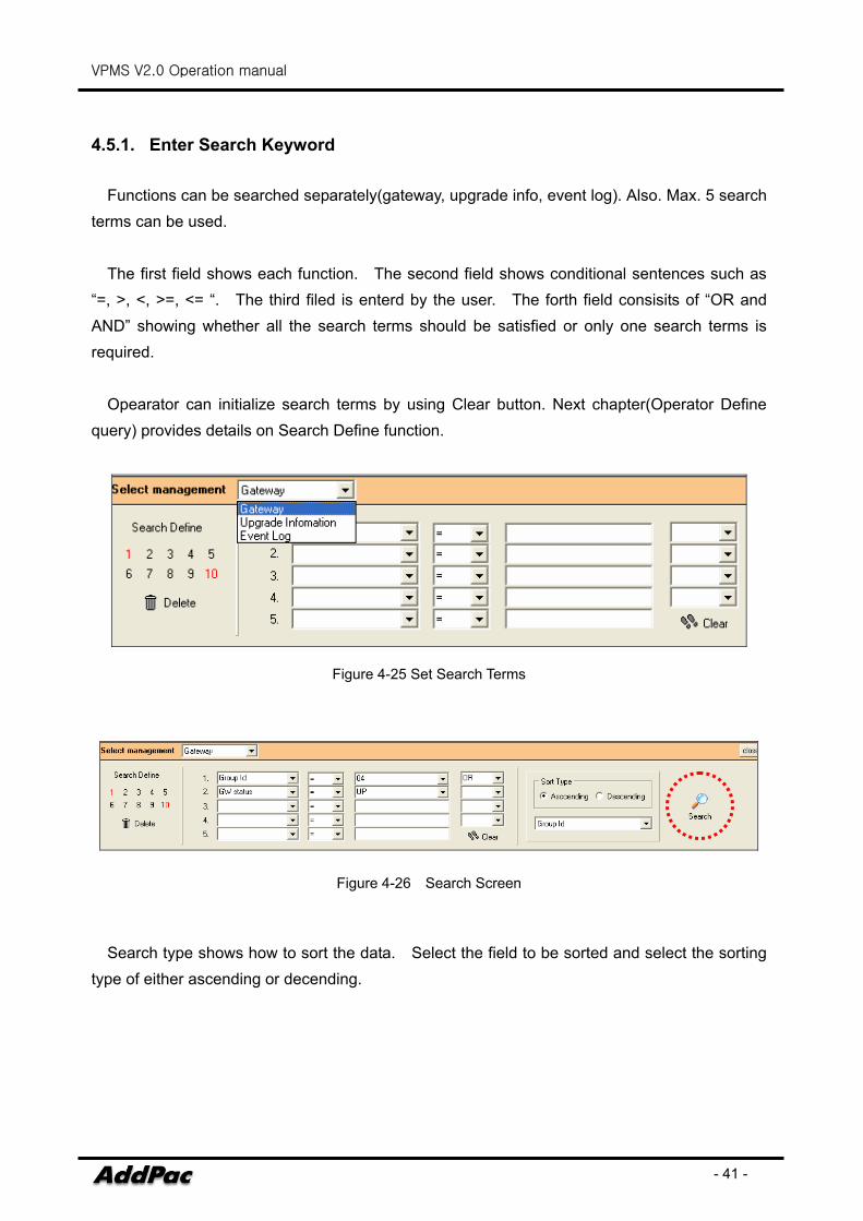
4.5.1. Enter Search Keyword
Functions can be searched separately(gateway, upgrade info, event log). Also. Max. 5 search terms can be used.
The first field shows each function. The second field shows conditional sentences such as “=, >, <, >=, <= “. The third filed is enterd by the user. The forth field consisits of “OR and AND” showing whether all the search terms should be satisfied or only one search terms is required.
Opearator can initialize search terms by using Clear button. Next chapter(Operator Define query) provides details on Search Define function.
Figure 4-25 Set Search Terms
Figure 4-26 Search Screen
Search type shows how to sort the data. Select the field to be sorted and select the sorting
type of either ascending or decending.
VPMS V2.0 Operation manual
- 42 -
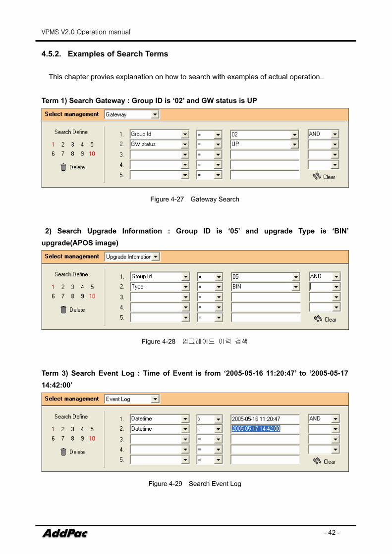
4.5.2. Examples of Search Terms
This chapter provies explanation on how to search with examples of actual operation..
Term 1) Search Gateway : Group ID is ‘02’ and GW status is UP
Figure 4-27 Gateway Search
2) Search Upgrade Information : Group ID is ‘05’ and upgrade Type is ‘BIN’ upgrade(APOS image)
Figure 4-28 업그레이드 이력 검색
Term 3) Search Event Log : Time of Event is from ‘2005-05-16 11:20:47’ to ‘2005-05-17 14:42:00’
Figure 4-29 Search Event Log
VPMS V2.0 Operation manual
- 43 -
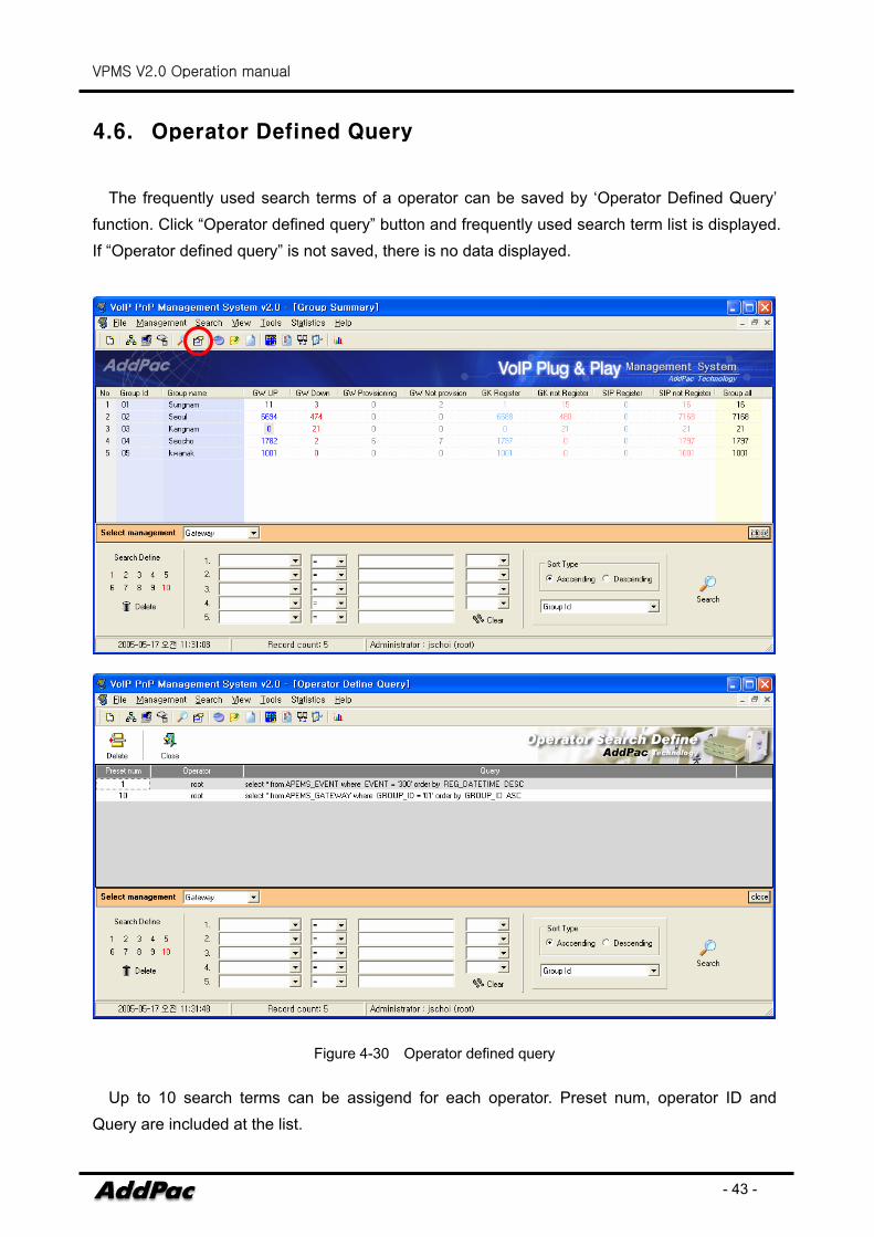
4.6. Operator Defined Query
The frequently used search terms of a operator can be saved by ‘Operator Defined Query’ function. Click “Operator defined query” button and frequently used search term list is displayed. If “Operator defined query” is not saved, there is no data displayed.
Figure 4-30 Operator defined query
Up to 10 search terms can be assigend for each operator. Preset num, operator ID and Query are included at the list.
VPMS V2.0 Operation manual
- 44 -
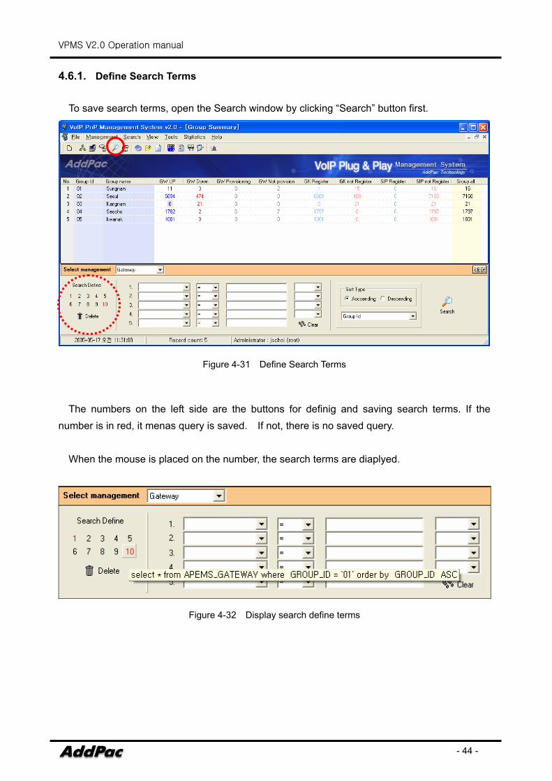
4.6.1. Define Search Terms
To save search terms, open the Search window by clicking “Search” button first.
Figure 4-31 Define Search Terms
The numbers on the left side are the buttons for definig and saving search terms. If the
number is in red, it menas query is saved. If not, there is no saved query.
When the mouse is placed on the number, the search terms are diaplyed.
Figure 4-32 Display search define terms
VPMS V2.0 Operation manual
- 45 -
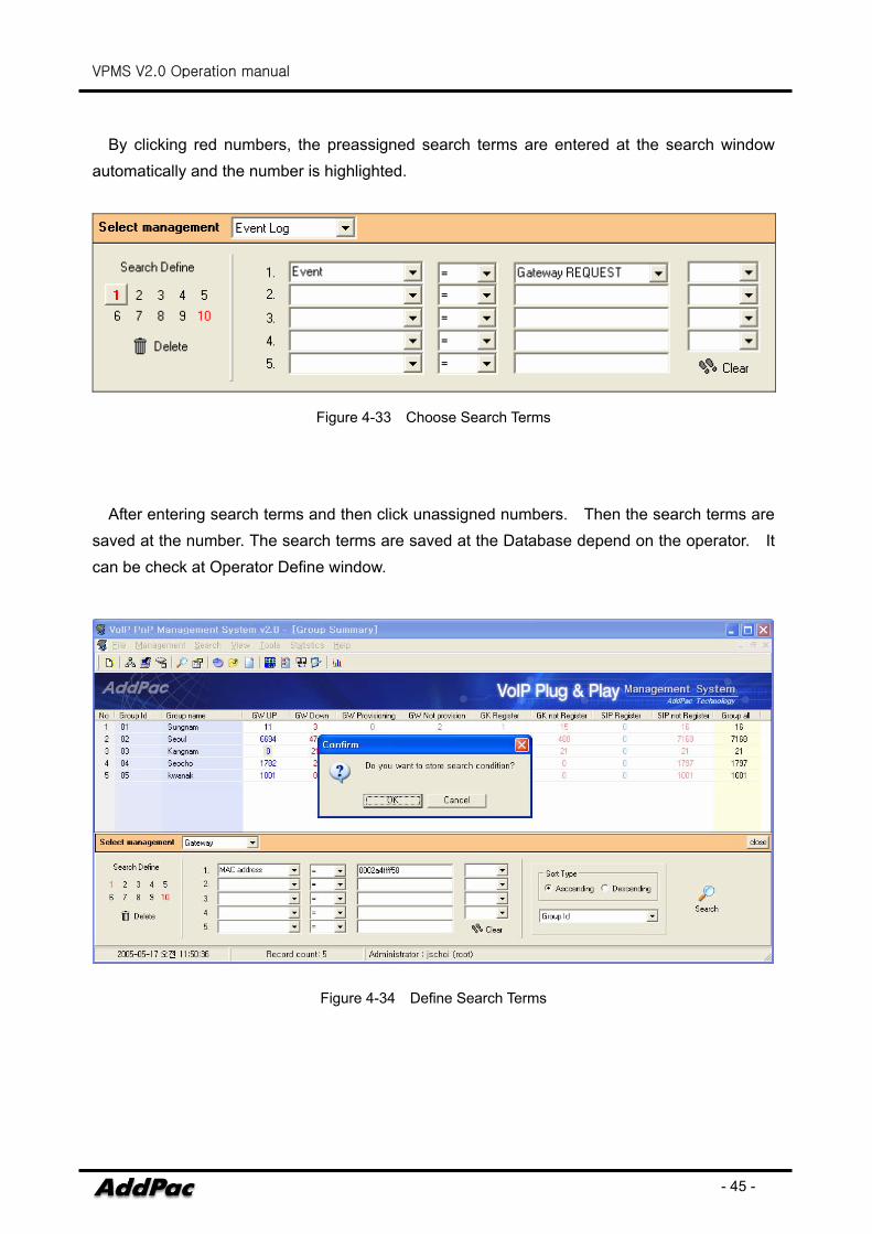
By clicking red numbers, the preassigned search terms are entered at the search window
automatically and the number is highlighted.
Figure 4-33 Choose Search Terms
After entering search terms and then click unassigned numbers. Then the search terms are saved at the number. The search terms are saved at the Database depend on the operator. It can be check at Operator Define window.
Figure 4-34 Define Search Terms
VPMS V2.0 Operation manual
- 46 -
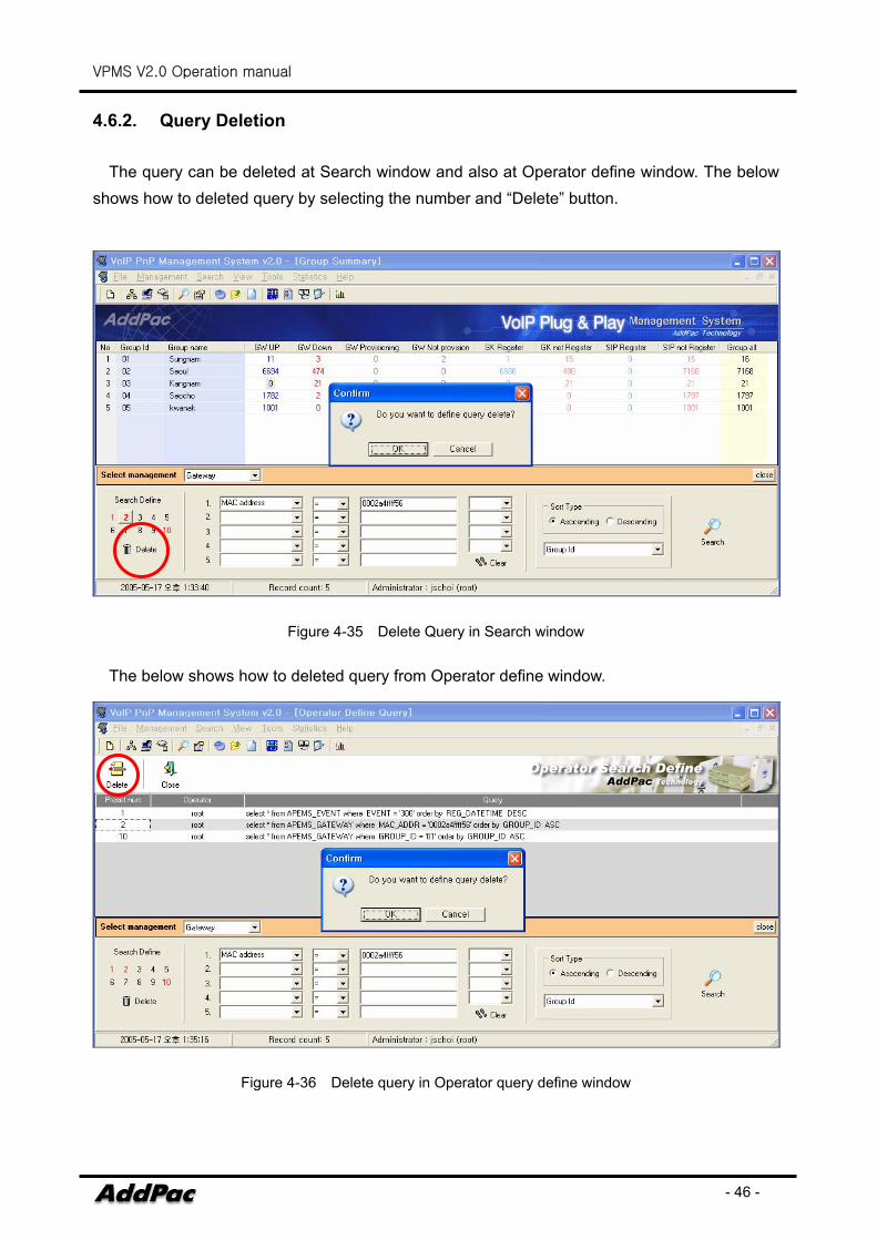
4.6.2. Query Deletion
The query can be deleted at Search window and also at Operator define window. The below shows how to deleted query by selecting the number and “Delete” button.
Figure 4-35 Delete Query in Search window
The below shows how to deleted query from Operator define window.
Figure 4-36 Delete query in Operator query define window
VPMS V2.0 Operation manual
- 47 -
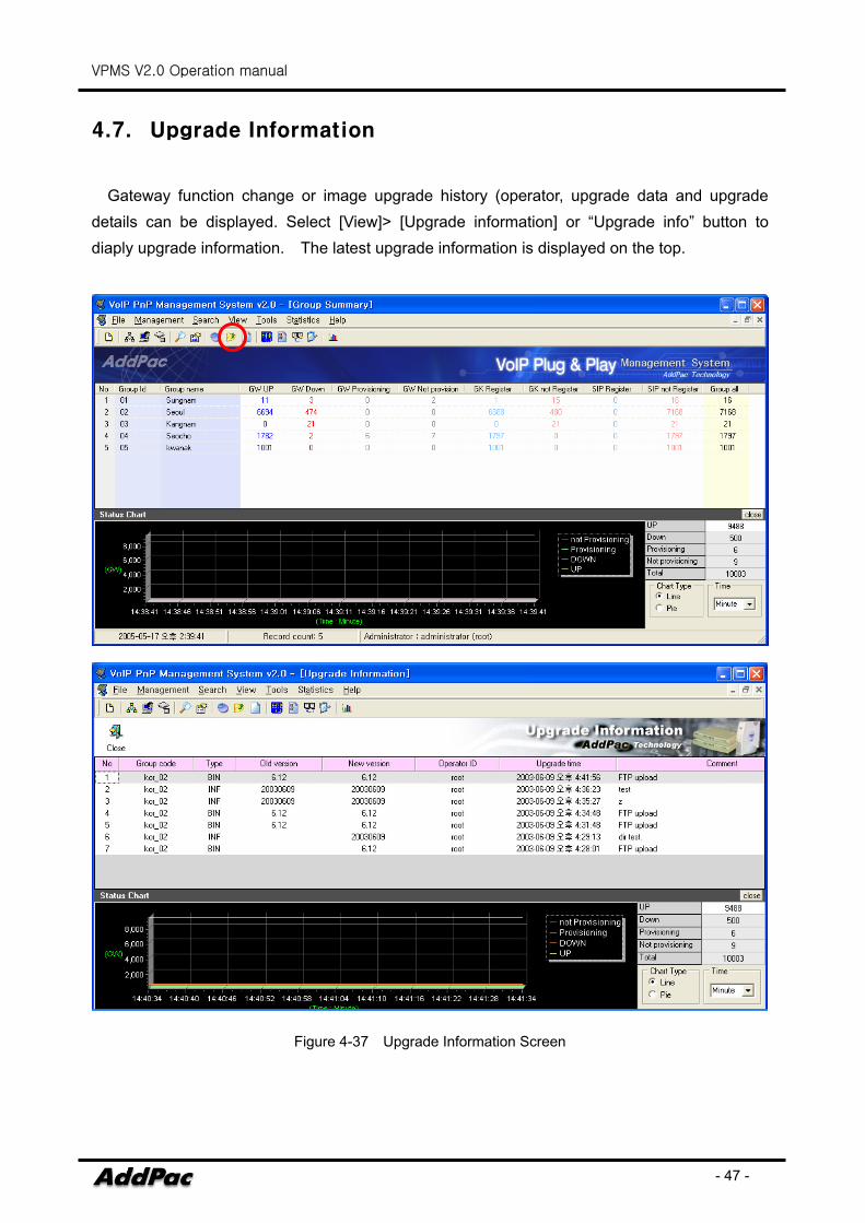
4.7. Upgrade Information
Gateway function change or image upgrade history (operator, upgrade data and upgrade details can be displayed. Select [View]> [Upgrade information] or “Upgrade info” button to diaply upgrade information. The latest upgrade information is displayed on the top.
Figure 4-37 Upgrade Information Screen
VPMS V2.0 Operation manual
- 48 -
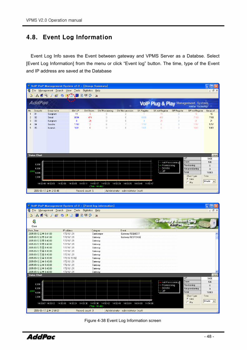
4.8. Event Log Information
Event Log Info saves the Event between gateway and VPMS Server as a Databse. Select [Event Log Information] from the menu or click “Event log” button. The time, type of the Event and IP address are saved at the Database
Figure 4-38 Event Log Information screen
VPMS V2.0 Operation manual
- 49 -
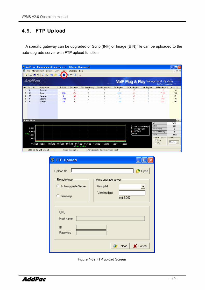
4.9. FTP Upload
A specific gateway can be upgraded or Scrip (INF) or Image (BIN) file can be uploaded to the auto-upgrade server with FTP upload function.
Figure 4-39 FTP upload Screen
VPMS V2.0 Operation manual
- 50 -
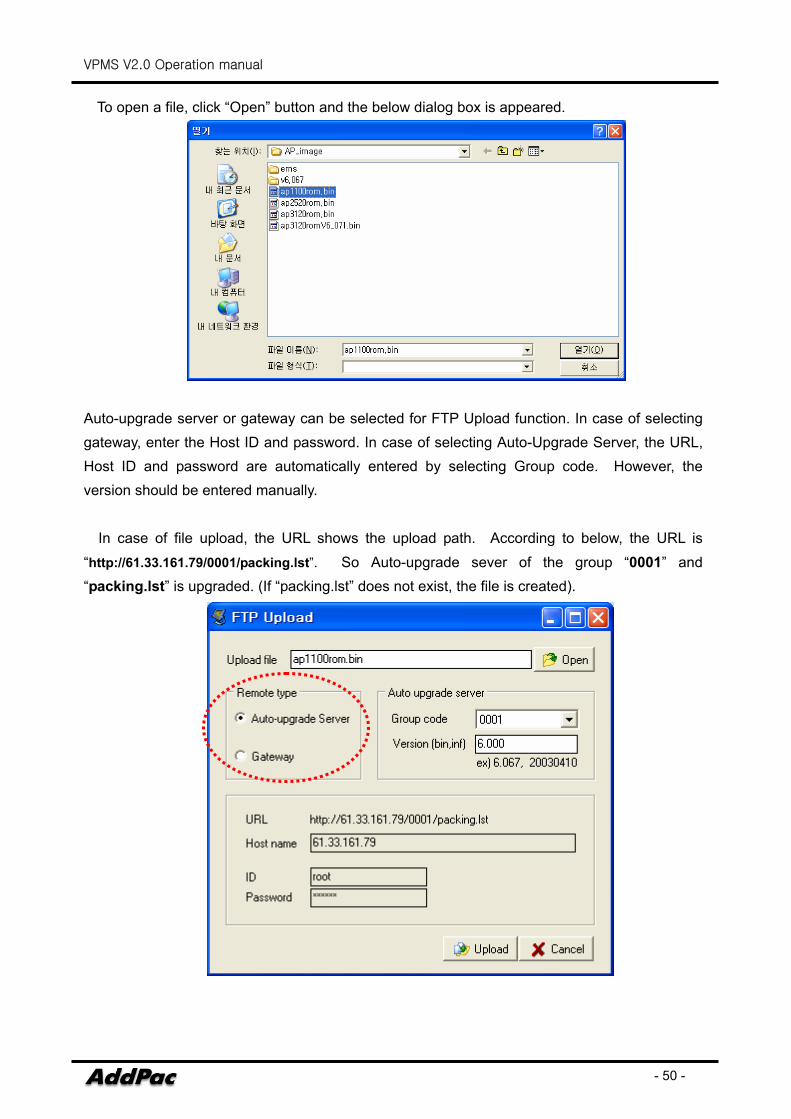
To open a file, click “Open” button and the below dialog box is appeared.
Auto-upgrade server or gateway can be selected for FTP Upload function. In case of selecting gateway, enter the Host ID and password. In case of selecting Auto-Upgrade Server, the URL, Host ID and password are automatically entered by selecting Group code. However, the version should be entered manually.
In case of file upload, the URL shows the upload path. According to below, the URL is
“http://61.33.161.79/0001/packing.lst”. So Auto-upgrade sever of the group “0001” and “packing.lst” is upgraded. (If “packing.lst” does not exist, the file is created).
VPMS V2.0 Operation manual
- 51 -
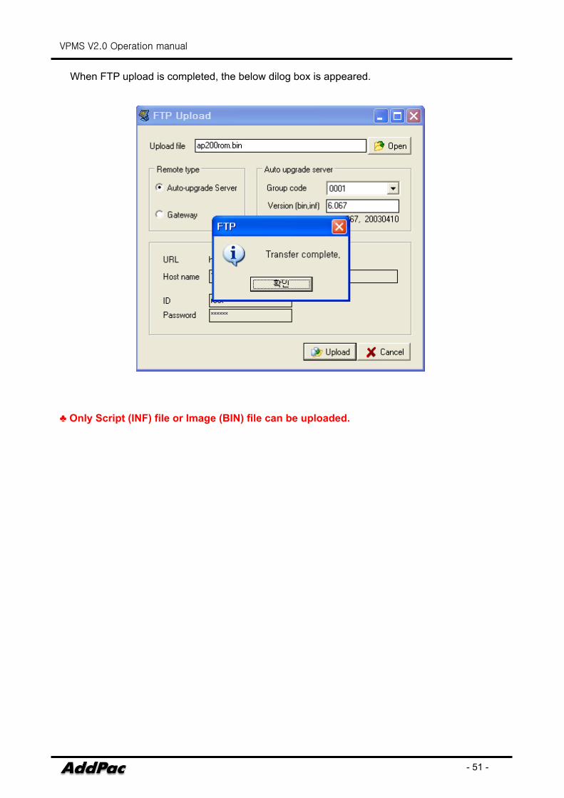
When FTP upload is completed, the below dilog box is appeared.
♣ Only Script (INF) file or Image (BIN) file can be uploaded.
VPMS V2.0 Operation manual
- 52 -
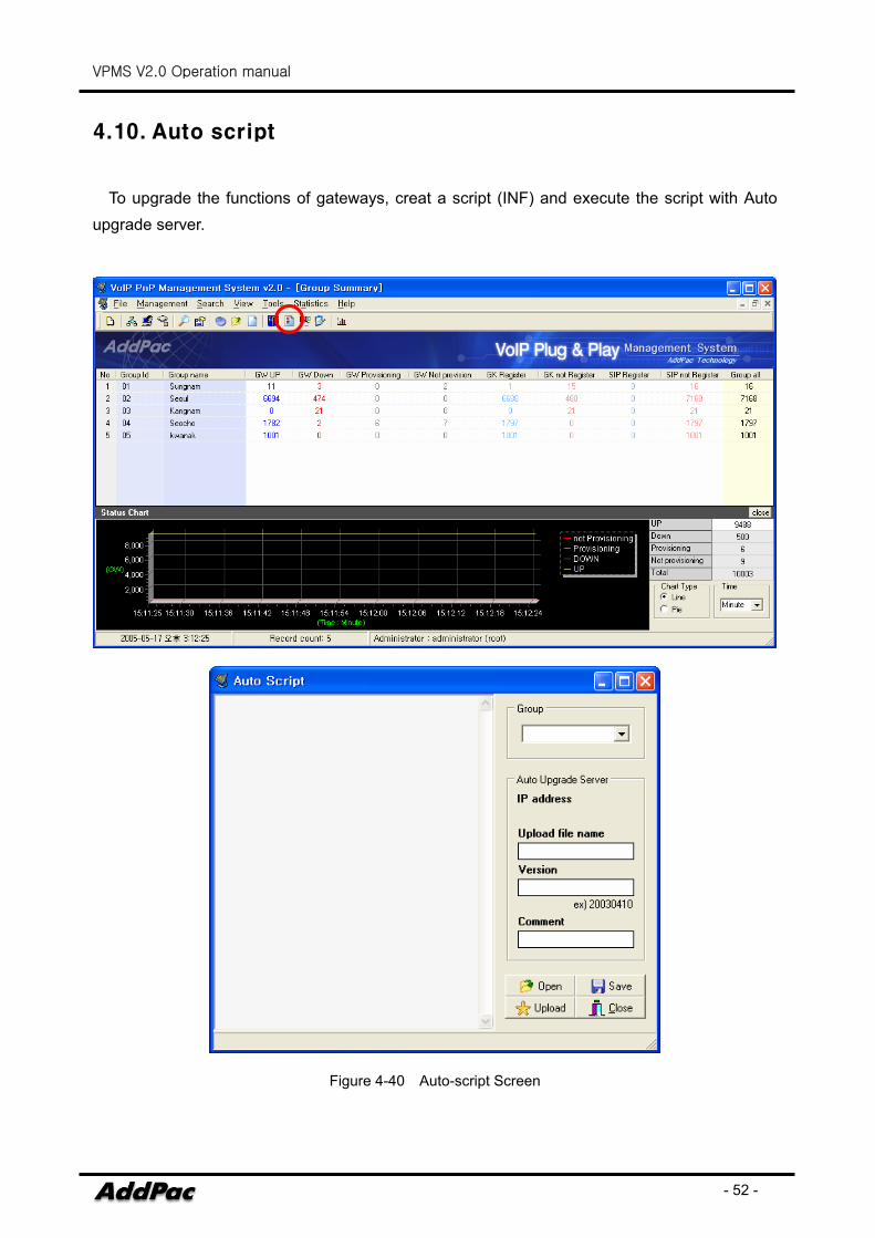
4.10. Auto script
To upgrade the functions of gateways, creat a script (INF) and execute the script with Auto upgrade server.
Figure 4-40 Auto-script Screen
VPMS V2.0 Operation manual
- 53 -
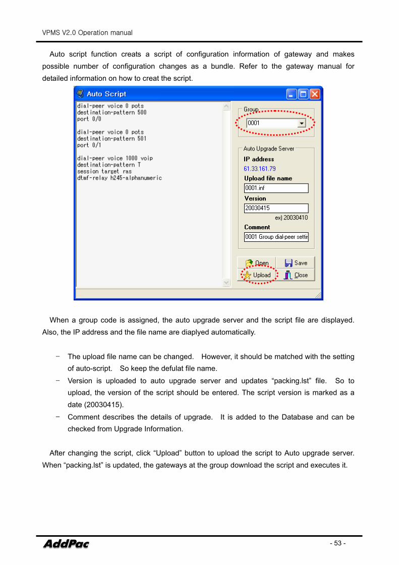
Auto script function creats a script of configuration information of gateway and makes possible number of configuration changes as a bundle. Refer to the gateway manual for detailed information on how to creat the script.
When a group code is assigned, the auto upgrade server and the script file are displayed. Also, the IP address and the file name are diaplyed automatically.
- The upload file name can be changed. However, it should be matched with the setting of auto-script. So keep the defulat file name.
- Version is uploaded to auto upgrade server and updates “packing.lst” file. So to upload, the version of the script should be entered. The script version is marked as a date (20030415).
- Comment describes the details of upgrade. It is added to the Database and can be checked from Upgrade Information.
After changing the script, click “Upload” button to upload the script to Auto upgrade server.
When “packing.lst” is updated, the gateways at the group download the script and executes it.
VPMS V2.0 Operation manual
- 54 -
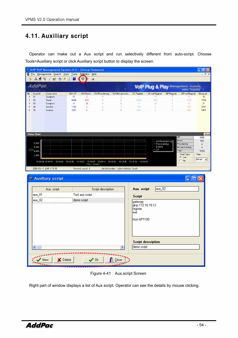
4.11. Auxiliary script
Operator can make out a Aux script and run selectively different from auto-script. Choose
Tools>Auxiliary script or click Auxiliary script button to display the screen.
Figure 4-41 Aux.script Screen
Right part of window displays a list of Aux script. Operator can see the details by mouse clicking.
VPMS V2.0 Operation manual
- 55 -
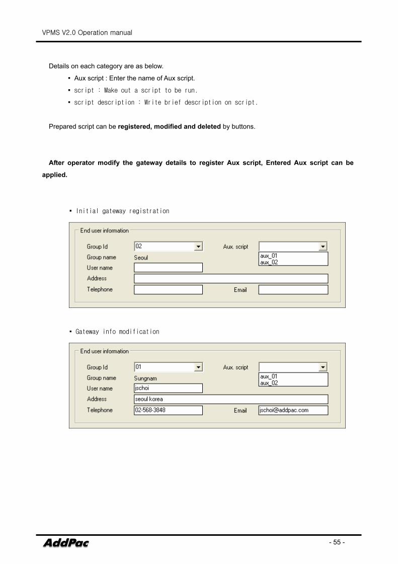
Details on each category are as below.
▪ Aux script : Enter the name of Aux script.
▪ script : Make out a script to be run.
▪ script description : Write brief description on script.
Prepared script can be registered, modified and deleted by buttons.
After operator modify the gateway details to register Aux script, Entered Aux script can be
applied.
▪ Initial gateway registration
▪ Gateway info modification
VPMS V2.0 Operation manual
- 56 -
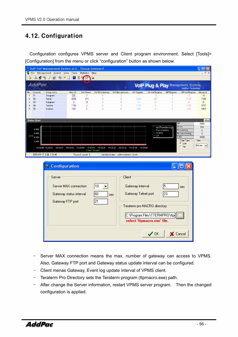
4.12. Configuration
Configuration configures VPMS server and Client program environment. Select [Tools]> [Configuration] from the menu or click “configuration” button as shown below.
- Server MAX connection means the max. number of gateway can access to VPMS.
Also, Gateway FTP port and Gateway status update interval can be configured.
- Client menas Gateway, Event log update interval of VPMS client. - Teraterm Pro Directory sets the Teraterm program (ttpmacro.exe) path. - After change the Server information, restart VPMS server program. Then the changed
configuration is applied.
VPMS V2.0 Operation manual
- 57 -
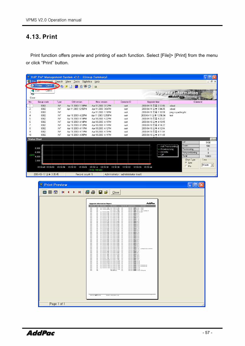
4.13. Print
Print function offers previw and printing of each function. Select [File]> [Print] from the menu or click “Print” button.
VPMS V2.0 Operation manual
- 58 -
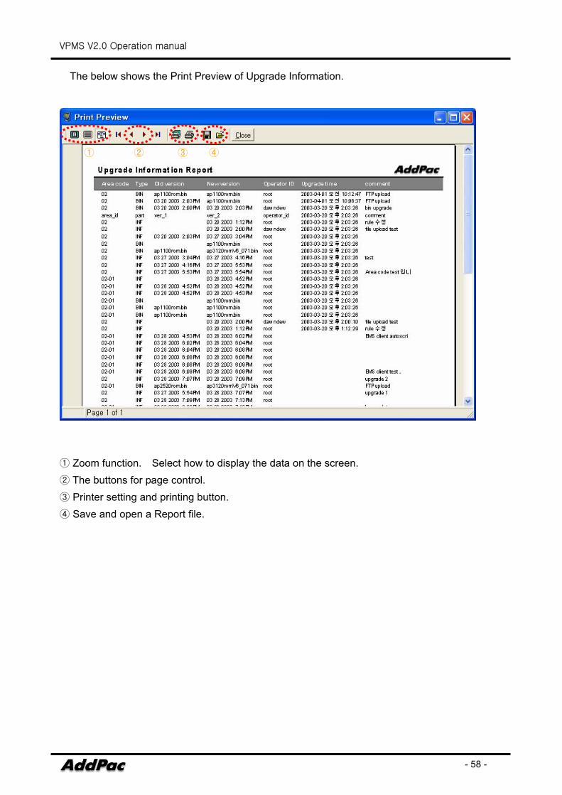
The below shows the Print Preview of Upgrade Information.
① Zoom function. Select how to display the data on the screen. ② The buttons for page control. ③ Printer setting and printing button. ④ Save and open a Report file.
① ② ③ ④
VPMS V2.0 Operation manual
- 59 -
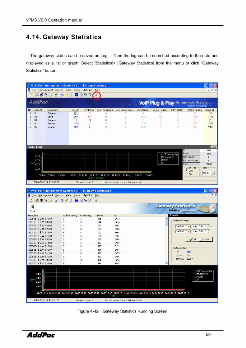
4.14. Gateway Statistics
The gateway status can be saved as Log. Then the log can be searched according to the date and
displayed as a list or graph. Select [Statistics]> [Gateway Statistics] from the menu or click “Gateway
Statistics” button.
Figure 4-42 Gateway Statistics Running Screen
VPMS V2.0 Operation manual
- 60 -
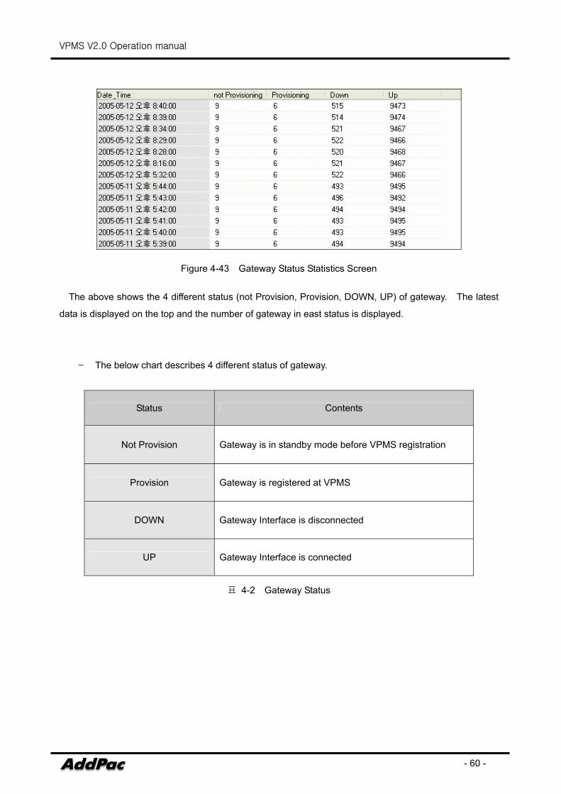
Figure 4-43 Gateway Status Statistics Screen
The above shows the 4 different status (not Provision, Provision, DOWN, UP) of gateway. The latest
data is displayed on the top and the number of gateway in east status is displayed.
- The below chart describes 4 different status of gateway.
Status Contents
Not Provision Gateway is in standby mode before VPMS registration
Provision Gateway is registered at VPMS
DOWN Gateway Interface is disconnected
UP Gateway Interface is connected
표 4-2 Gateway Status
VPMS V2.0 Operation manual
- 61 -
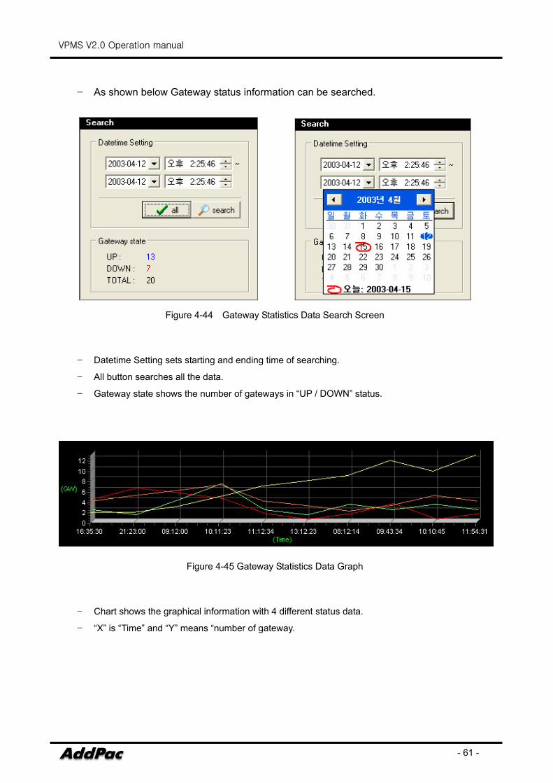
- As shown below Gateway status information can be searched.
Figure 4-44 Gateway Statistics Data Search Screen
- Datetime Setting sets starting and ending time of searching.
- All button searches all the data.
- Gateway state shows the number of gateways in “UP / DOWN” status.
Figure 4-45 Gateway Statistics Data Graph
- Chart shows the graphical information with 4 different status data.
- “X” is “Time” and “Y” means “number of gateway.
VPMS V2.0 Operation manual
- 62 -
5. An Example of VPMS Operation Scenario
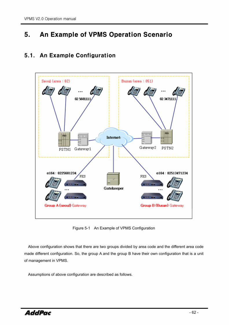
5.1. An Example Configuration
Figure 5-1 An Example of VPMS Configuration
Above configuration shows that there are two groups divided by area code and the different area code
made different configuration. So, the group A and the group B have their own configuration that is a unit
of management in VPMS.
Assumptions of above configuration are described as follows.
VPMS V2.0 Operation manual
- 63 -
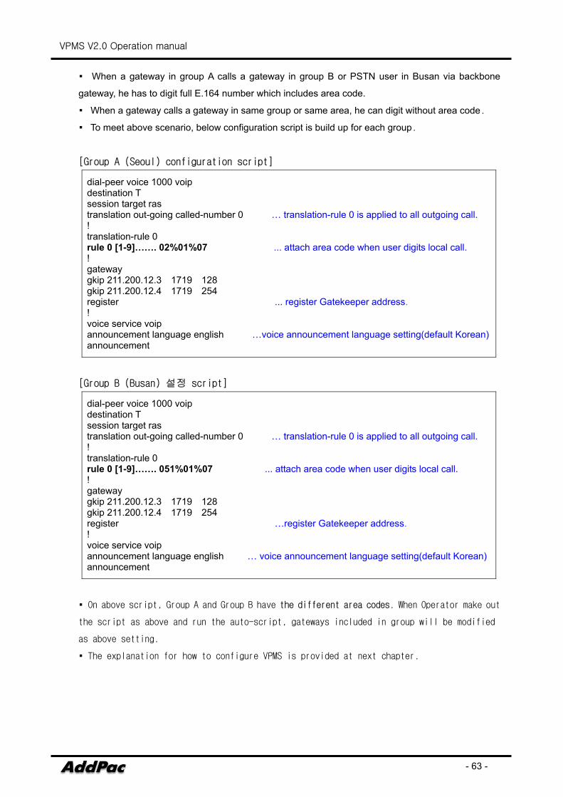
▪ When a gateway in group A calls a gateway in group B or PSTN user in Busan via backbone
gateway, he has to digit full E.164 number which includes area code.
▪ When a gateway calls a gateway in same group or same area, he can digit without area code.
▪ To meet above scenario, below configuration script is build up for each group.
[Group A (Seoul) configuration script]
dial-peer voice 1000 voip destination T session target ras translation out-going called-number 0 … translation-rule 0 is applied to all outgoing call. ! translation-rule 0 rule 0 [1-9]……. 02%01%07 ... attach area code when user digits local call. ! gateway gkip 211.200.12.3 1719 128 gkip 211.200.12.4 1719 254 register ... register Gatekeeper address. ! voice service voip announcement language english …voice announcement language setting(default Korean)announcement
[Group B (Busan) 설정 script]
dial-peer voice 1000 voip destination T session target ras translation out-going called-number 0 … translation-rule 0 is applied to all outgoing call. ! translation-rule 0 rule 0 [1-9]……. 051%01%07 ... attach area code when user digits local call. ! gateway gkip 211.200.12.3 1719 128 gkip 211.200.12.4 1719 254 register …register Gatekeeper address. ! voice service voip announcement language english … voice announcement language setting(default Korean) announcement
▪ On above script, Group A and Group B have the different area codes. When Operator make out
the script as above and run the auto-script, gateways included in group will be modified
as above setting.
▪ The explanation for how to configure VPMS is provided at next chapter.
VPMS V2.0 Operation manual
- 64 -
5.2. Group A Gateway Initial Setting
Gateway initial setting must be done before being sent to customers. Group A and B in Chapter
4.1 has no difference except the area code. The explanation Group A(Seoul) shall be proceeded.
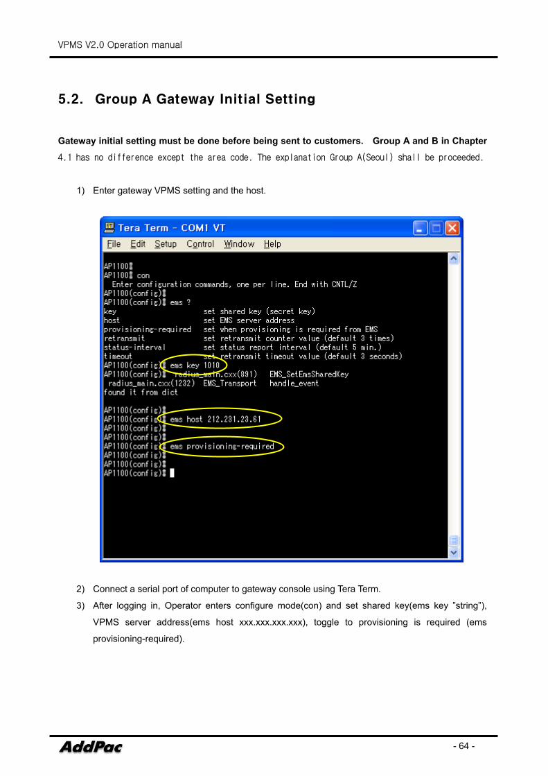
1) Enter gateway VPMS setting and the host.
2) Connect a serial port of computer to gateway console using Tera Term.
3) After logging in, Operator enters configure mode(con) and set shared key(ems key ”string”),
VPMS server address(ems host xxx.xxx.xxx.xxx), toggle to provisioning is required (ems
provisioning-required).
VPMS V2.0 Operation manual
- 65 -
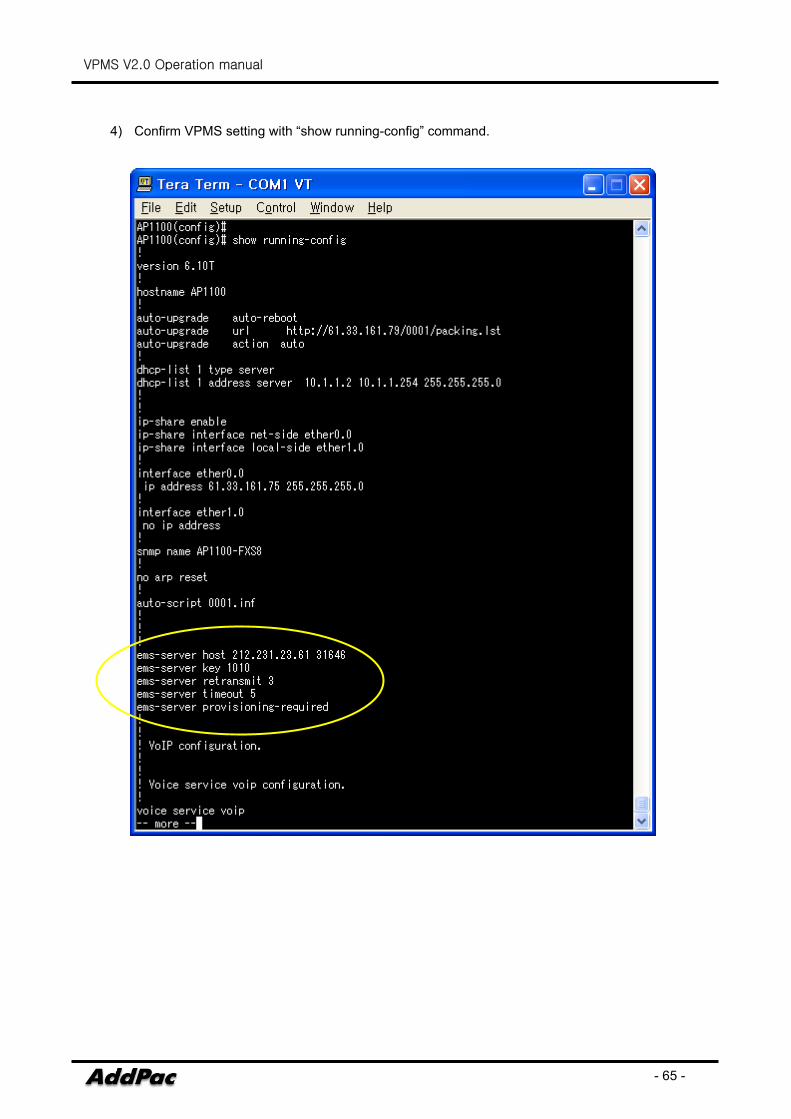
4) Confirm VPMS setting with “show running-config” command.
VPMS V2.0 Operation manual
- 66 -
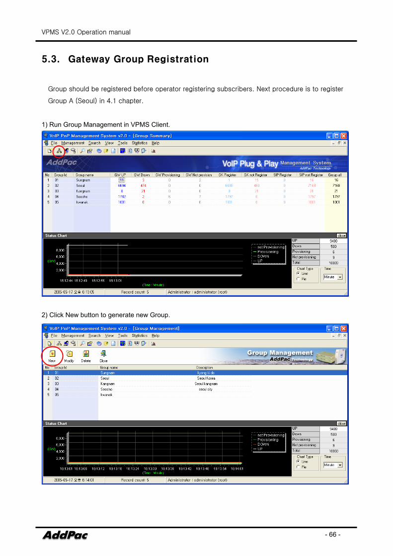
5.3. Gateway Group Registration
Group should be registered before operator registering subscribers. Next procedure is to register
Group A (Seoul) in 4.1 chapter.
1) Run Group Management in VPMS Client.
2) Click New button to generate new Group.
VPMS V2.0 Operation manual
- 67 -
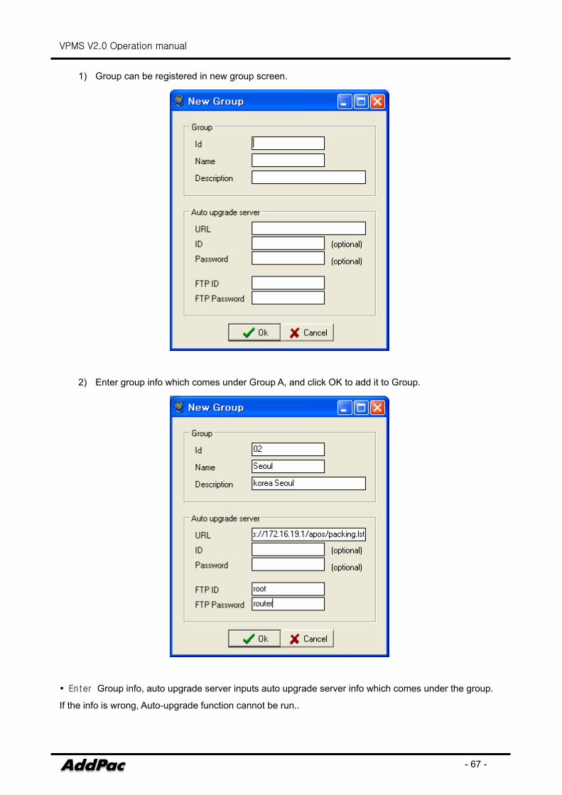
1) Group can be registered in new group screen.
2) Enter group info which comes under Group A, and click OK to add it to Group.
▪ Enter Group info, auto upgrade server inputs auto upgrade server info which comes under the group.
If the info is wrong, Auto-upgrade function cannot be run..
VPMS V2.0 Operation manual
- 68 -
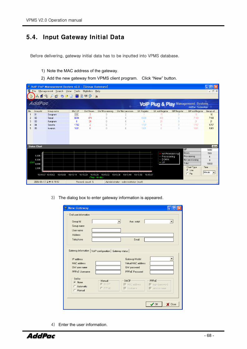
5.4. Input Gateway Initial Data
Before delivering, gateway initial data has to be inputted into VPMS database.
1) Note the MAC address of the gateway.
2) Add the new gateway from VPMS client program. Click “New” button.
3) The dialog box to enter gateway information is appeared.
4) Enter the user information.
VPMS V2.0 Operation manual
- 69 -
VPMS V2.0 Operation manual
- 70 -
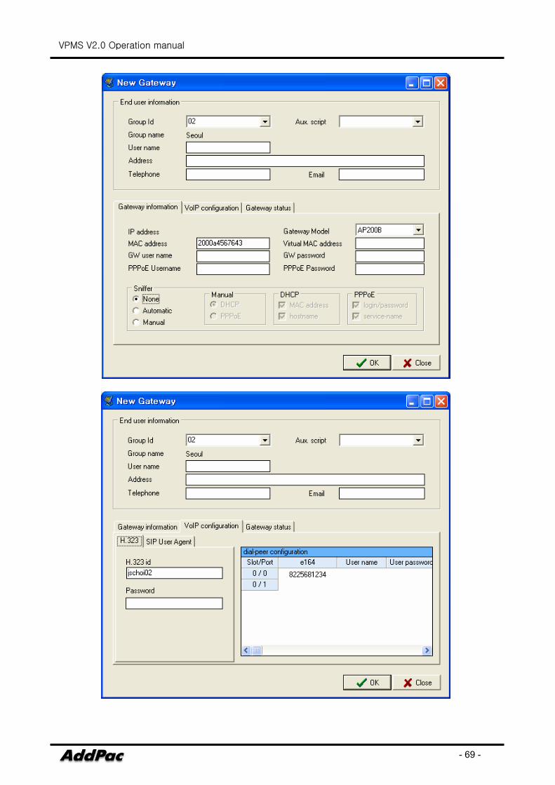
- Enter Group code, MAC address, password, H323id, e164 and Model.
- Set code “ 02” and e164 “ 8225681234” which comes under Group-A.
- The other user information can be added when the user is requested for the servicing by
matching the MAC address.
- After registering user information, you can ship the product to the user.
5.5. End-customer Gateway Setting
1) After receiving the gateway, the customer installs the gateway.
2) If the customer does not apply for the service, they should applied for the service (via telephone
or Internet) first. The user information and MAC address of the gateway are required to apply
for the service.
3) Connect existing Internet line to the WAN (LAN0) port of the gateway. Then connect the LAN
(LAN1) port to PC LAN port with the supplied LAN cable.
4) Refer to the Voice Finder user manual for more detailed information.
5) When the power is supplied to the gateway connected to the Internet, the gateway connects to
VPMS with the gateway information (MAC address and IP address). If there is no reply from
the VPMS, the gateway regularly tries to access VPMS.
5.6. Gateway Info generation and Installation
1) VPMS server waits for the gateway requesting for the basic information of the gateway. When
the request is received, VPMS looks up for the gateway information from VPMS Database based
on MAC address.
2) VPMS server monitors the IP address and condition of the gateway. Also, it saves the data at
the Database.
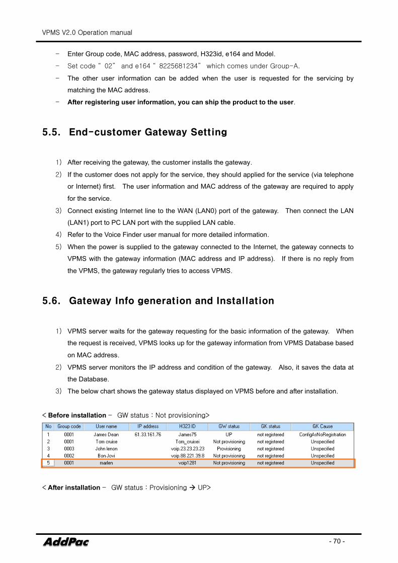
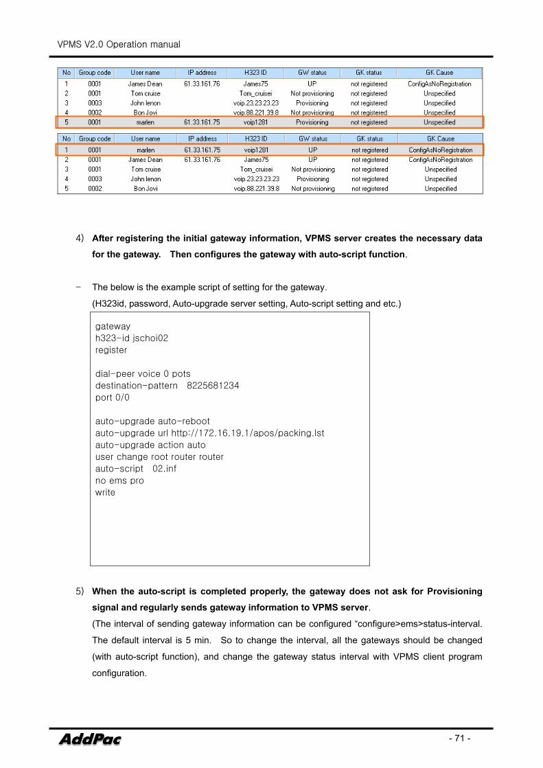
3) The below chart shows the gateway status displayed on VPMS before and after installation.
< Before installation – GW status : Not provisioning>
< After installation – GW status : Provisioning UP>
VPMS V2.0 Operation manual
- 71 -
4) After registering the initial gateway information, VPMS server creates the necessary data
for the gateway. Then configures the gateway with auto-script function.
- The below is the example script of setting for the gateway.
(H323id, password, Auto-upgrade server setting, Auto-script setting and etc.)
gateway
h323-id jschoi02
register
dial-peer voice 0 pots
destination-pattern 8225681234
port 0/0
auto-upgrade auto-reboot
auto-upgrade url http://172.16.19.1/apos/packing.lst
auto-upgrade action auto
user change root router router
auto-script 02.inf
no ems pro
write
5) When the auto-script is completed properly, the gateway does not ask for Provisioning
signal and regularly sends gateway information to VPMS server.
(The interval of sending gateway information can be configured “configure>ems>status-interval.
The default interval is 5 min. So to change the interval, all the gateways should be changed
(with auto-script function), and change the gateway status interval with VPMS client program
configuration.
VPMS V2.0 Operation manual
- 72 -
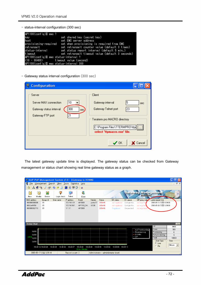
- status-interval configuration (300 sec)
- Gateway status interval configuration (300 sec)
The latest gateway update time is displayed. The gateway status can be checked from Gateway
management or status chart showing real time gateway status as a graph.
VPMS V2.0 Operation manual
- 73 -
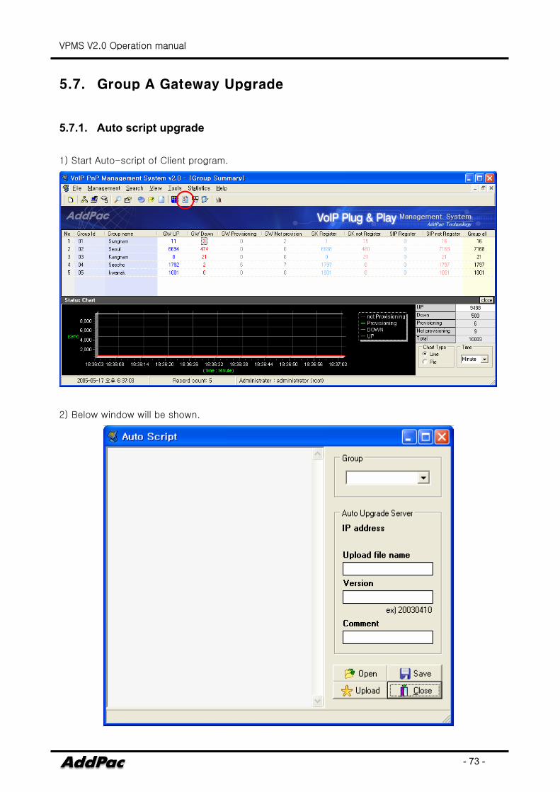
5.7. Group A Gateway Upgrade
5.7.1. Auto script upgrade
1) Start Auto-script of Client program.
2) Below window will be shown.
VPMS V2.0 Operation manual
- 74 -
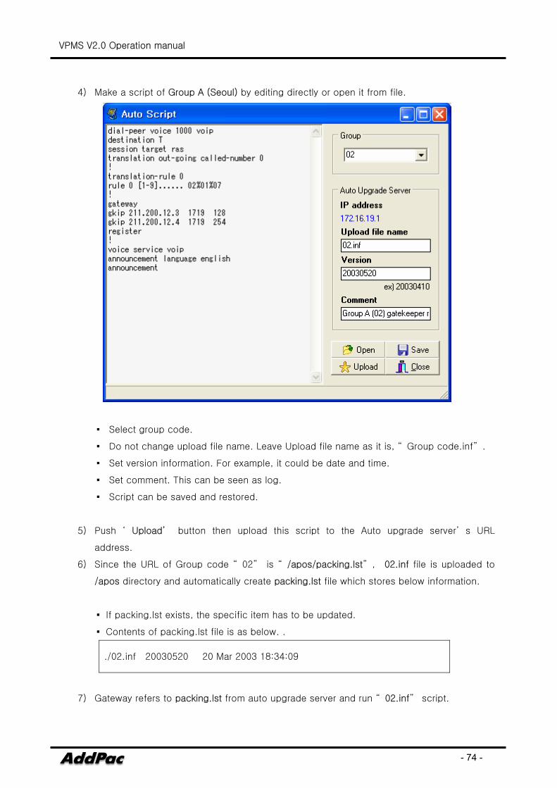
4) Make a script of Group A (Seoul) by editing directly or open it from file.
▪ Select group code.
▪ Do not change upload file name. Leave Upload file name as it is, “ Group code.inf” .
▪ Set version information. For example, it could be date and time.
▪ Set comment. This can be seen as log.
▪ Script can be saved and restored.
5) Push ‘ Upload’ button then upload this script to the Auto upgrade server’ s URL
address.
6) Since the URL of Group code “ 02” is “ /apos/packing.lst” , 02.inf file is uploaded to
/apos directory and automatically create packing.lst file which stores below information.
▪ If packing.lst exists, the specific item has to be updated.
▪ Contents of packing.lst file is as below. .
./02.inf 20030520 20 Mar 2003 18:34:09
7) Gateway refers to packing.lst from auto upgrade server and run “ 02.inf” script.

VPMS V2.0 Operation manual
- 75 -
8) After the gateways of Group A (Seoul : 02) set as initial configuration, the gateway will
download this script.
▪ The gateway which comes under Group A (Seoul : 02) is registered to Gatekeeper automatically,
and a subscriber which has the gateway dial “ 5681111” , PSTN number in same Seoul area, area
code(02) is automatically inputted to call. in Seoul area PSTN network phone number
“ 5681111” .
VPMS V2.0 Operation manual
- 76 -
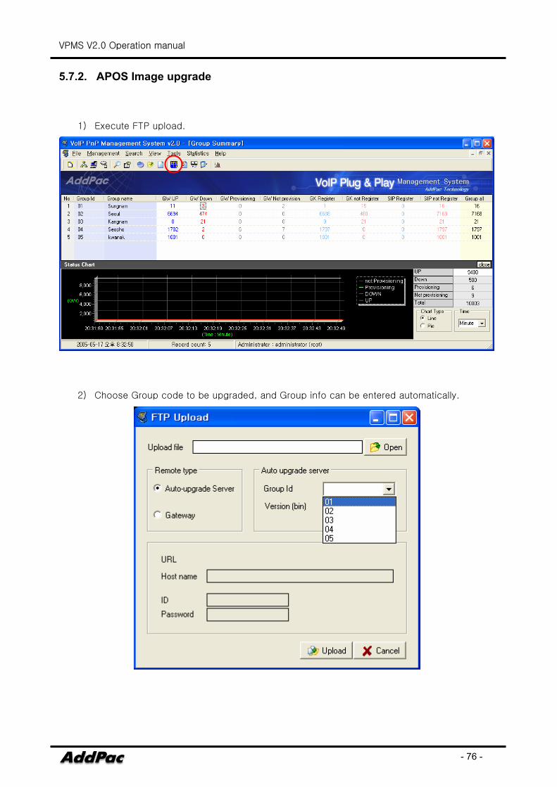
5.7.2. APOS Image upgrade
1) Execute FTP upload.
2) Choose Group code to be upgraded, and Group info can be entered automatically.
VPMS V2.0 Operation manual
- 77 -
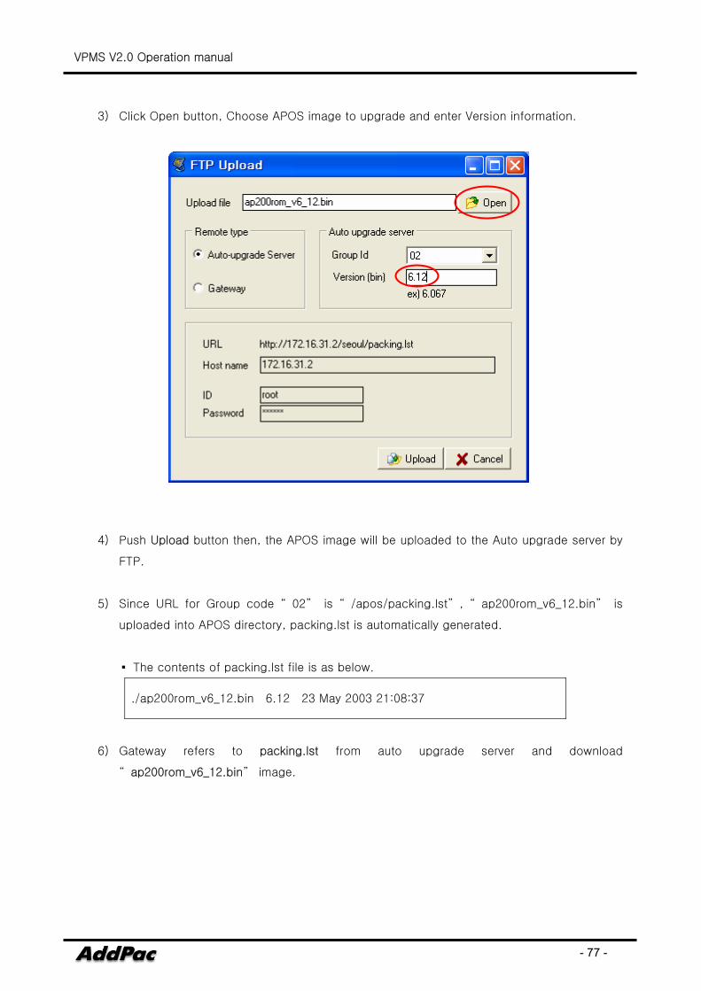
3) Click Open button, Choose APOS image to upgrade and enter Version information.
4) Push Upload button then, the APOS image will be uploaded to the Auto upgrade server by
FTP.
5) Since URL for Group code “ 02” is “ /apos/packing.lst” , “ ap200rom_v6_12.bin” is
uploaded into APOS directory, packing.lst is automatically generated.
▪ The contents of packing.lst file is as below.
./ap200rom_v6_12.bin 6.12 23 May 2003 21:08:37
6) Gateway refers to packing.lst from auto upgrade server and download
“ ap200rom_v6_12.bin” image.


![4 ZXMSG 5200 (V2[1].0.2) Operation Manual](https://img.pdfslide.us/doc/110x75/577c98551a28ab163a8b564a/4-zxmsg-5200-v2102-operation-manual.jpg)
