Embed Size (px)
Citation preview
1 2 3
1 2 3
Operation & Maintenance Manual
K Arowana Series-V2
6.Installation method
6.4.3.Pendant mount
6.4.2.Wall mount
Ceiling mount
Hole location
Pendant mount Wall mount Pipe clamp
6.4.4.Pipe clamp
1 2 3
expansion anchor bolts: M10
Expansion anchor bolts location for ceiling mount
1 2 3
Pipe clamp bracket location
6.5.Select suitable three core cable(OD8-14mm)with strip length(L:110mm, N:85mm, GND:40mm) .
SHENZHEN KHJ SEMICONDUCTOR LIGHTING CO., LTD.
Install the brackets Wall mountExpansion anchor bolts location for wall mount
Install the brackets Ceiling mount
Pendant mountInstall the loopsExpansion anchor bolts location for Pendant mount
Pipe clampPipe clamp bracket fix on the pole
unit:mm
unit:mm
unit:mm unit:mm
unit:mm
unit:mm unit:mm
unit:mm
unit:mmunit:mm
φ40-60
Explosion Proof Lighting
Industrial Lighting
Ex d ⅡB T6 GbEx tb ⅢC T80℃ Db Ip66
Add: 4-5 Floor,Building 1,Chuangxin industrial park,Xintian community,Guanlan,Longhua new district,Shenzhen,ChinaTel: +86-755-82949977Fax: +86-755-82949800Web: www.khjled.com
1.Brief Introduction1.1.LED source, aluminium alloy explosion proof enclosure. Small size, high safety and stability.
2.Application2.1.Ex type: a.Petroleum Industry, Petrochemical Industry, Metallurgical Industry, Power Generation Industry, Power Transmission Industry, Machine Manufacturing. etc. b.Drilling platform, single point moorings, oil tanks, work over platform, production platform, field tank, manifold center,pumping station, gasoline station, transformer station,coating plant warehouse .etc.2.3. Ambient temperature from -40℃ to 55℃.
3.Executive standard3.1.EN 60079-0
3.2.EN 60079-1
3.3.EN 60079-31
3.4IEC 60079-0
3.5. IEC 60079-1
3.6.IEC 60079-31
3.7.EN 55015
3.8.EN 60598-13.9.EN 62321
4.Product certification4.1. ATEX, IECEX,ABS,CE and RoHS.
5.Caution5.1. This product should be installed and maintained by qualified electrician only.5.2. Do not operate in ambient temperatures above those indicated on the nameplate.5.3. Repair of the flameproof joint must be made in compliance with the structural specifications provided by the manufacturer.5.4. The assembly should be equipped with certified cable glands with a compatible mode of protection for the intended use. The unused holes should be closed by certified plugs.5.5. Make sure the electrical power is OFF before making installation and maintenance.5.6.Do not open when energized.5.7. After de-energizing, delay 10 minutes before opening.5.8. Typically full discharging and charging once every half a year.
Explosive atmospheres-Part 0:Equipment-General requiementsExplosive atmospheres-Part 1:Equipment protection by flameproof enclosures "d"Explosive atmospheres-Part 31:Equipment dust ignition protection by enclosure"t"Explosive atmospheres-Part 0:Equipment-General requiementsExplosive atmospheres-Part 1:Equipment protection by flameproof enclosures "d"Explosive atmospheres-Part 31:Equipment dust ignition protection by enclosure"t"Limits and methods of measurement of radio disturbancecharacteristics of electrical lighting and similar equipmentLuminaires-Part 1: General requirements and testsElectrotechnical products - Determination of levels of sixregulated substances (lead, mercury, cadmium, hexavalentchromium, polybrominated biphenyls, polybrominated diphenyl ethers)
6.1.Install M10 expansion anchor bolts correctly as per different installtion methods.6.2.Fix the brackets to the right places on the light fitting.6.3.Fix the light fitting with flat washer, lock washer and bolt nut to the expansion anchor bolts.6.4.Installation drawings: 6.4.1. Ceiling mount
Three core cable OD: φ 8-14 mm
earth wirelive wire
neutral wire
/
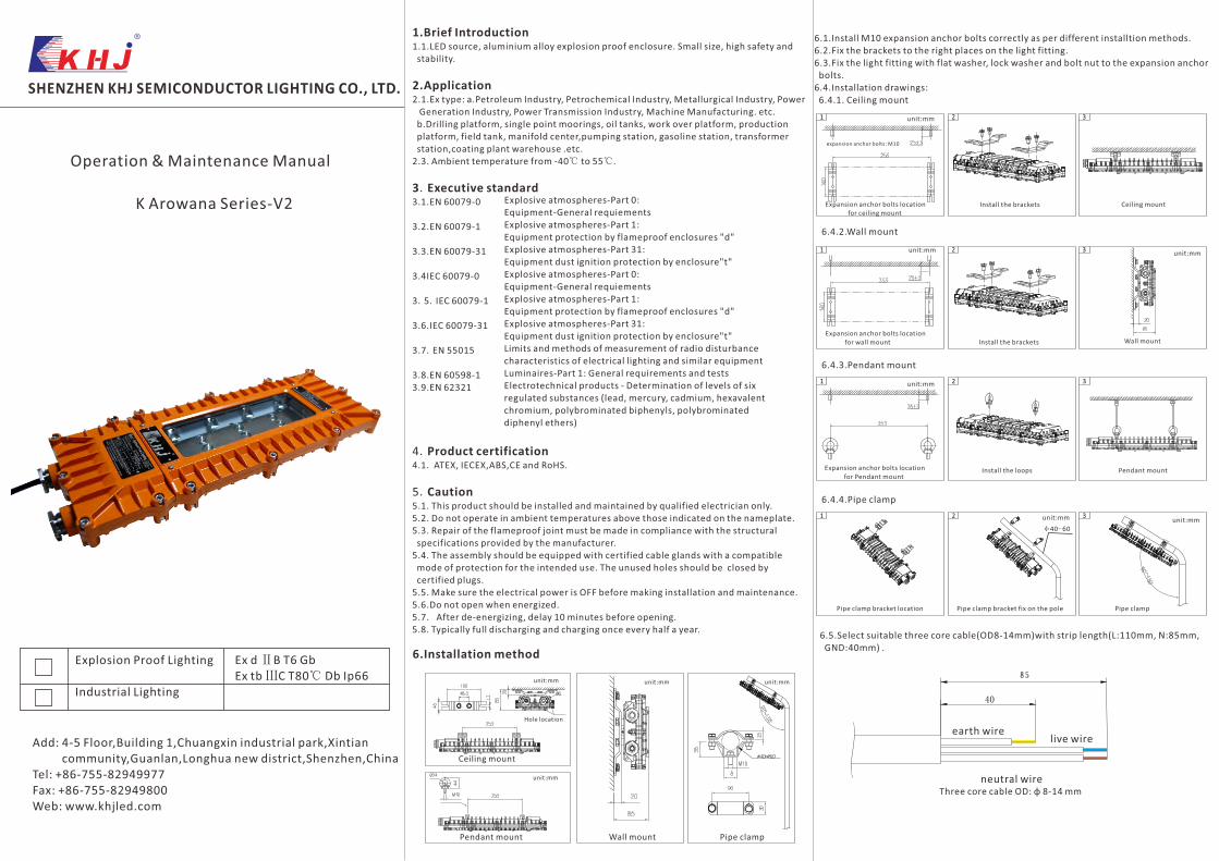
5mm hex wrench
Remove 5pcs M6 screws on the terminal compartment cover
flat washer
gland nut rubber seal
Please note the order of gland nut, flat washer and rubber seal
GND Internal
GND External
safety chain
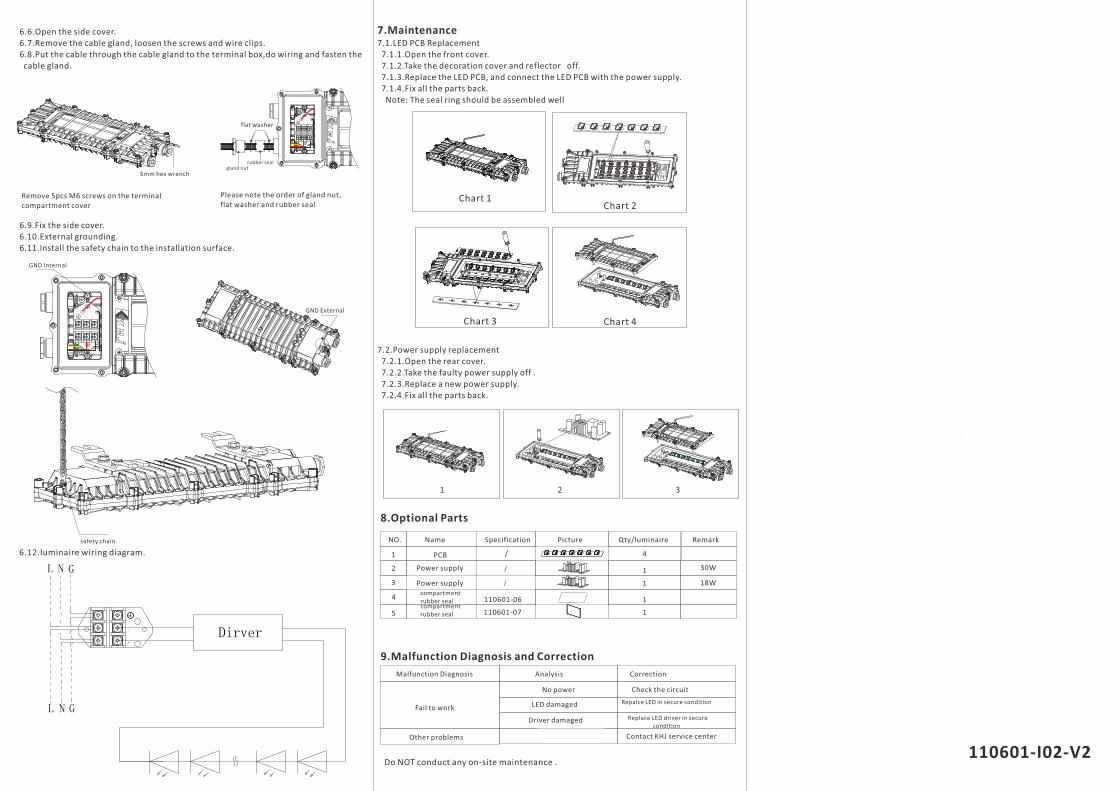
Chart 1Chart 2
Chart 3 Chart 4
1 2 3
8.Optional Parts
NO. Name Specification Picture Qty/luminaire Remark
1
2
3
5
4
PCB
Power supply
Power supplycompartment rubber sealcompartment rubber seal
9.Malfunction Diagnosis and Correction
Malfunction Diagnosis Analysis Correction
Fail to work
Other problems
No power Check the circuit
LED damaged Repalce LED in secure condition
Driver damaged Replace LED driver in secure condition
Contact KHJ service center
Do NOT conduct any on-site maintenance .
30W
18W
/
/
110601-06
110601-07
4
1
1
1
1
L
N
L N
L N
110601-I02-V2
6.6.Open the side cover.6.7.Remove the cable gland, loosen the screws and wire clips.6.8.Put the cable through the cable gland to the terminal box,do wiring and fasten the cable gland.
6.9.Fix the side cover.6.10.External grounding.6.11.Install the safety chain to the installation surface.
6.12.luminaire wiring diagram.
7.Maintenance7.1.LED PCB Replacement 7.1.1.Open the front cover. 7.1.2.Take the decoration cover and reflector off. 7.1.3.Replace the LED PCB, and connect the LED PCB with the power supply. 7.1.4.Fix all the parts back. Note: The seal ring should be assembled well
7.2.Power supply replacement 7.2.1.Open the rear cover. 7.2.2.Take the faulty power supply off . 7.2.3.Replace a new power supply. 7.2.4.Fix all the parts back.
![Asian Bonytongue (Scleropages formosus) ERSS...From Arowana Fish For Sale (2019): “Asian Red Arowana $250.00 – $410.00 […] Scleropages formosus they have common name Asian arowana](https://img.pdfslide.us/doc/110x75/5ff26d1db5943925ea359d97/asian-bonytongue-scleropages-formosus-erss-from-arowana-fish-for-sale-2019.jpg)