Embed Size (px)
Citation preview
VACUUM ANDPRESSURE SYSTEMS
HANDBOOK(revised electronic edition)

2
VACUUM AND PRESSURE SYSTEMSHANDBOOK
copyright © Gast Manufacturing, Inc All Rights Reserved
Gast Manufacturing, IncA Unit of IDEX CorporationPO BOX 972300 M-139Benton Harbor, MI 49023-0097Ph: 616/926-6171Fax: 616/927-0860http://www.gastmfg.com/[email protected]

3
INTRODUCTIONINTRODUCTIONINTRODUCTIONINTRODUCTIONINTRODUCTION
This handbook examines two interrelated segments of pneumatic power: pres-sure and vacuum. That is, the development and utilization of air pressure andvacuum to meet specific work needs.
In terms of system equipment, this translates largely (but not exclusively) intothe proper selection and sizing of commercial air compressors and vacuumpumps. The focus here is on smaller units-those appropriate to powering anindividual machine or, at most, a small shop.
The basic principles are equally applicable to the much larger units supplyingcompressed air or vacuum as a utility to an entire plant, but this book makes noattempt to deal with the practical aspects of selecting and utilizing these large-sometimes very large-machines. The emphasis throughout is on practical ap-proaches to designing small pneumatic power systems for today's complex andsophisticated needs.
While this handbook treats vacuum and pressure systems in separate sections,keep in mind that some applications require both vacuum and pressure. Forexample, in thermoforming plastic cups, first air pressure, then vacuum is re-quired. Instead of installing separate systems, a combination compressor/vacuum pump can provide pneumatic power for both functions.
When a unit is used to provide pressure and vacuum simultaneously rather thansequentially, however, the loads must be carefully balanced. Separate units areusually preferred for this type of application.
Handbook Sections
Whatever the application, the correct pneumatic power system can help meettoday's increasing demands for greater machine productivity, reliability andoperator safety and convenience. The information in this handbook will help youattain these objectives.
The basic concepts of pressure and vacuum are covered in Section 1. Separatesections are devoted to the selection and operation of air compressors (Section11) and vacuum pumps (Section IV).
Sections III and V cover accessories, work devices, and overall considerations forpressure and vacuum systems, respectively. Section VI covers combination com-pressor/vacuum pump systems. Section VII includes some representative prob-lem/solution applications.
The appendix summarizes gas laws and related data. It also includes tables givingdata on pressure loss due to friction, pipe bends and components, and on air flowthrough various-size orifices. A glossary appears at the end of the volume.
4
Contents
Introduction ......................................................................................................... 3
Section IBasic Concepts - Vacuum and Pressure .......................................................... 6Pneumatics and Pneumatic Power ....................................................................... 6Basic Advantages.................................................................................................. 8Pressure Levels and Terminology ......................................................................... 9Units of Pressure/Vacuum Measurement ............................................................ 14Measurement of Pressure and Vacuum .............................................................. 14Pressure/Volume/ Temperature Relationships .................................................... 18
Section IIAIR COMPRESSORS......................................................................................... 21Pressure Generation: Compression .................................................................... 21Compression Work Requirements ...................................................................... 21Air Compressors: Basic Operation ...................................................................... 22Positive Displacement Compressors .................................................................. 22Nonpositive Displacement Compressors ............................................................ 33Compressor Controls and Cycling ...................................................................... 37Selection of Compressor Type ............................................................................ 39Compressor Size Selection ................................................................................. 45Other Selection Considerations .......................................................................... 47
Section IIIPRESSURE ACCESSORIES AND SYSTEMS................................................... 53Summary of Pressure Sequence ........................................................................ 53Transmission of Pressure.................................................................................... 59Storage of Compressed Air ................................................................................. 59Control of Compressed Air .................................................................................. 60Effects of Pressure: Force ................................................................................... 62Pneumatic Power Supply Systems ..................................................................... 63
5
Section IVVACUUM PUMPS ............................................................................................... 69Vacuum Pumps: Basic Operation........................................................................ 69Vacuum Stages ................................................................................................... 70Oil-Less vs. Oil-Lubricated Vacuum Pumps ........................................................ 70Positive Displacement Vacuum Pumps ............................................................... 70Nonpositive Displacement Vacuum Pumps ........................................................ 72Evaluating Vacuum Pump Performance ............................................................. 72Effects of Temperature Rise ................................................................................ 77Vacuum Pump Selection ..................................................................................... 77Drive Power Selection ......................................................................................... 81
SECTION VVACUUM ACCESSORIES AND SYSTEMS ....................................................... 86Conditioning Air Flow in Vacuum Systems .......................................................... 86Storage of Vacuum.............................................................................................. 88Control of Vacuum............................................................................................... 88Effects of Vacuum: Force .................................................................................... 89Vacuum Power Supply Systems ......................................................................... 91Combined Compressor/ ...................................................................................... 98Vacuum Pump Systems ...................................................................................... 98Compressor/Vacuum Power Supply System ...................................................... 98Compressor/Vacuum Pump Selection ................................................................ 99
PROBLEMS & SOLUTIONS ........................................................................... 102
APPENDIX ........................................................................................................ 105
GLOSSARY ...................................................................................................... 114

6
BASIC CONCEPTS ----- ----- ----- ----- -----VACUUM AND PRESSURE
Pneumatics and Pneumatic Power
"Pneumatics" is the general term used to describe the mechanics of gases.And "pneumatic power" can be defined as: production or control of mechanicaloutputs for useful work by means of a pressurized gas in a closed circuit. In sim-plerlanguage, Fluid power provides a very reliable "muscle" function-ranging from',something as simple as pressure for blowing an air horn to vacuum for lifting ahuge metal workpiece into a precise position on a worktable. Although the definition allows for any gas, air is almost always used in practi-cal industrial systems. Only air is considered in the remainder of the book. Pneumatic power is one of the two branches of "fluid power." The other is"hydraulic power," in which the working fluid is a liquid. In pneumatic systems,unlike hydraulic systems, the pressures can be positive or negative. In pneumatic systems, the pressure differentials necessary to do work areproduced by air compressors. They push more air into the system, increasing thepressure above that of atmospheric air. In vacuum systems, the pressure differentials are produced by vacuumpumps. These pull air out of the system, decreasing the pressure below atmo-spheric. Even though we sometimes refer to vacuum as negative pressure, this can bemisleading. In an absolute sense, pressure is always positive. Pressure can be"negative" only in relation to some other, higher, pressure. But since we areconstantly surrounded by the atmosphere, it's often natural to describe belowatmospheric pressures as negative.
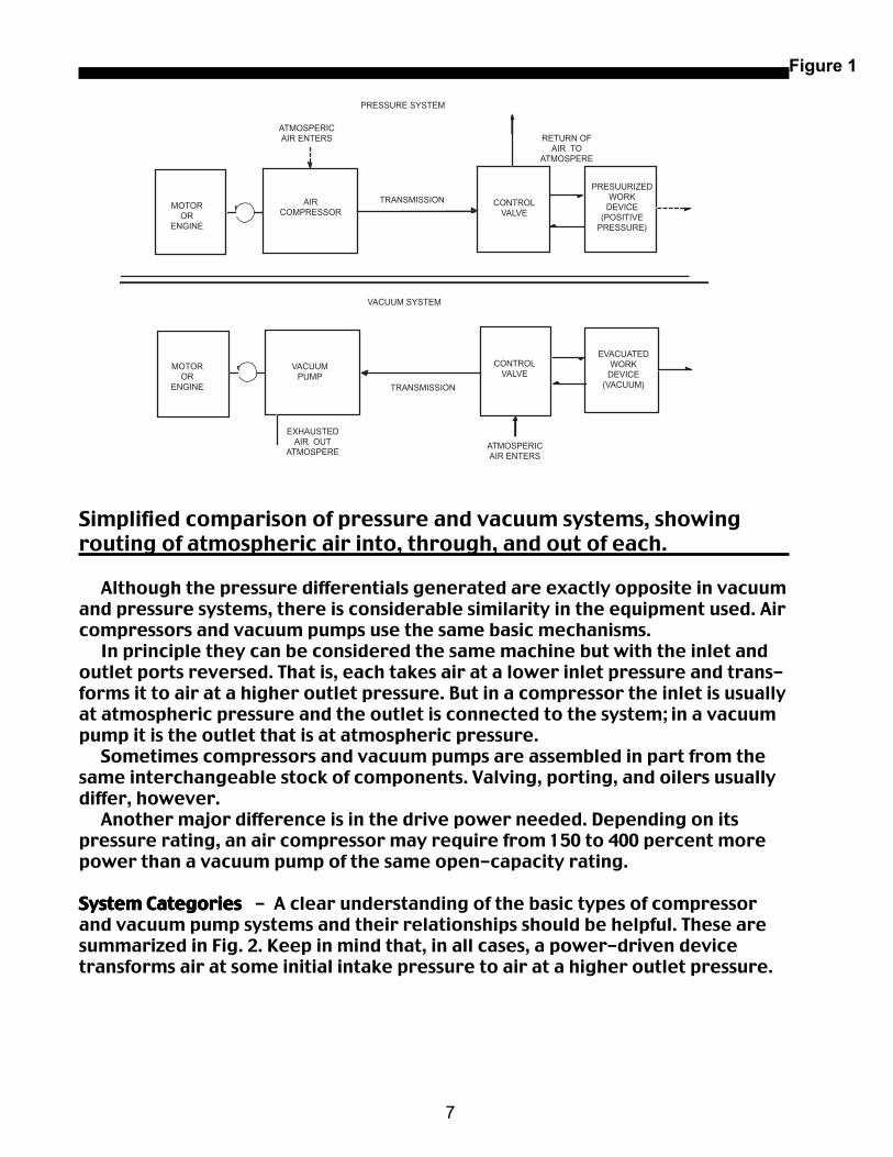
Compressed Air and Vacuum Systems Compressed Air and Vacuum Systems Compressed Air and Vacuum Systems Compressed Air and Vacuum Systems Compressed Air and Vacuum Systems- Fig. 1 compares the basic operation ofcompressed air and vacuum systems. In both systems a prime mover such as anelectric motor or gasoline engine operates an air compressor or vacuum pump,converting electrical or chemical energy into pneumatic energy. Note how atmospheric air enters and leaves each system, and the direction ofthe arrows indicating transmission of pneumatic energy. At the end of eachsystem, an appropriate control valve and work device (air cylinder, air motor,etc.) converts the pneumatic energy into useful mechanical force or power. Ineither case, the air is a working fluid that is unchanged over a complete operat-ing cycle.
Section I
7
Simplified comparison of pressure and vacuum systems, showingrouting of atmospheric air into, through, and out of each.
Although the pressure differentials generated are exactly opposite in vacuumand pressure systems, there is considerable similarity in the equipment used. Aircompressors and vacuum pumps use the same basic mechanisms. In principle they can be considered the same machine but with the inlet andoutlet ports reversed. That is, each takes air at a lower inlet pressure and trans-forms it to air at a higher outlet pressure. But in a compressor the inlet is usuallyat atmospheric pressure and the outlet is connected to the system; in a vacuumpump it is the outlet that is at atmospheric pressure. Sometimes compressors and vacuum pumps are assembled in part from thesame interchangeable stock of components. Valving, porting, and oilers usuallydiffer, however. Another major difference is in the drive power needed. Depending on itspressure rating, an air compressor may require from 150 to 400 percent morepower than a vacuum pump of the same open-capacity rating.
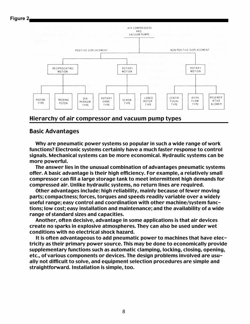
System Categories System Categories System Categories System Categories System Categories - A clear understanding of the basic types of compressorand vacuum pump systems and their relationships should be helpful. These aresummarized in Fig. 2. Keep in mind that, in all cases, a power-driven devicetransforms air at some initial intake pressure to air at a higher outlet pressure.
Figure 1
PRESSURE SYSTEM
VACUUM SYSTEM
ATMOSPERICAIR ENTERS RETURN OF
AIR TOATMOSPERE
ATMOSPERICAIR ENTERS
EXHAUSTEDAIR OUT
ATMOSPERE
TRANSMISSION
TRANSMISSIONMOTOR
ORENGINE
AIRCOMPRESSOR
CONTROLVALVE
PRESUURIZEDWORK
DEVICE(POSITIVE
PRESSURE)
MOTOROR
ENGINE
CONTROLVALVE
VACUUMPUMP
EVACUATEDWORK
DEVICE(VACUUM)
8
Hierarchy of air compressor and vacuum pump types
Basic Advantages
Why are pneumatic power systems so popular in such a wide range of workfunctions? Electronic systems certainly have a much faster response to controlsignals. Mechanical systems can be more economical. Hydraulic systems can bemore powerful. The answer lies in the unusual combination of advantages pneumatic systemsoffer. A basic advantage is their high efficiency. For example, a relatively smallcompressor can fill a large storage tank to meet intermittent high demands forcompressed air. Unlike hydraulic systems, no return lines are required. Other advantages include: high reliability, mainly because of fewer movingparts; compactness; forces, torques and speeds readily variable over a widelyuseful range; easy control and coordination with other machine/system func-tions; low cost; easy installation and maintenance; and the availability of a widerange of standard sizes and capacities. Another, often decisive, advantage in some applications is that air devicescreate no sparks in explosive atmospheres. They can also be used under wetconditions with no electrical shock hazard. It is often advantageous to add pneumatic power to machines that have elec-tricity as their primary power source. This may be done to economically providesupplementary functions such as automatic clamping, locking, closing, opening,etc., of various components or devices. The design problems involved are usu-ally not difficult to solve, and equipment selection procedures are simple andstraightforward. Installation is simple, too.
Figure 2
9
When the air compressor or vacuum pump is driven by a power takeoff fromthe machine it is being added to, the mounting location may be critical (al-though accessory air components may be placed almost anywhere). But if theunit is provided with its own drive motor, then virtually the entire system can beinstalled at any point-even away from the machine-as long as that point can bereached by a hose, pipe, or tube to transmit the pneumatic power. What are some of the drawbacks of pneumatic power systems? One is the need for a compressor and for distribution lines, compared to theconvenience of plugging an electric motor into an existing electric system. Another is the inevitable energy loss in converting electrical or chemicalenergy into pneumatic energy, which is then used to do work that the primemover could have done directly. In addition, pneumatic work devices are oftennot very energy efficient (20 percent efficiency is typical of air motors, for ex-ample). But in variable-load applications, this is offset by pneumatic devicesdrawing only the power actually needed. Most electric motors, by contrast,draw almost the same power regardless of load. And, of course, reasonably sized pneumatic devices cannot exert the forcesand torques that hydraulic devices can. In most applications, a horsepowerrating somewhere in the tens represents the crossover point at which the in-creasing size and cost of pneumatic devices begin to exceed the basic cost of ahydraulic power generation and transmission system. In summary, then, electric, hydraulic, and pneumatic systems each have theirplace. But the advantages of pneumatic power make it the system of choice inmany applications.
Pressure Levels and Terminology
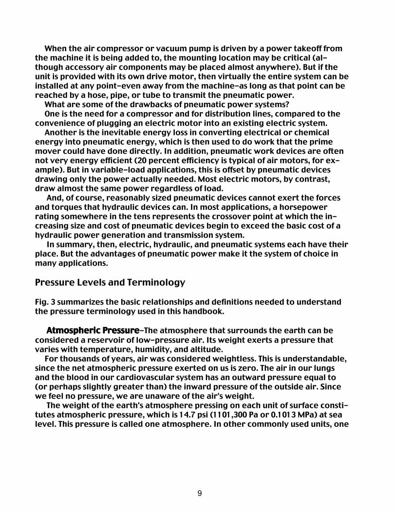
Fig. 3 summarizes the basic relationships and definitions needed to understandthe pressure terminology used in this handbook.
Atmospheric PressureAtmospheric PressureAtmospheric PressureAtmospheric PressureAtmospheric Pressure-The atmosphere that surrounds the earth can beconsidered a reservoir of low-pressure air. Its weight exerts a pressure thatvaries with temperature, humidity, and altitude. For thousands of years, air was considered weightless. This is understandable,since the net atmospheric pressure exerted on us is zero. The air in our lungsand the blood in our cardiovascular system has an outward pressure equal to(or perhaps slightly greater than) the inward pressure of the outside air. Sincewe feel no pressure, we are unaware of the air's weight. The weight of the earth's atmosphere pressing on each unit of surface consti-tutes atmospheric pressure, which is 14.7 psi (1101,300 Pa or 0.1013 MPa) at sealevel. This pressure is called one atmosphere. In other commonly used units, one
10
Figure 3Figure 3Figure 3Figure 3Figure 3
Summary of basic pressure measurement relationships.Summary of basic pressure measurement relationships.Summary of basic pressure measurement relationships.Summary of basic pressure measurement relationships.Summary of basic pressure measurement relationships.
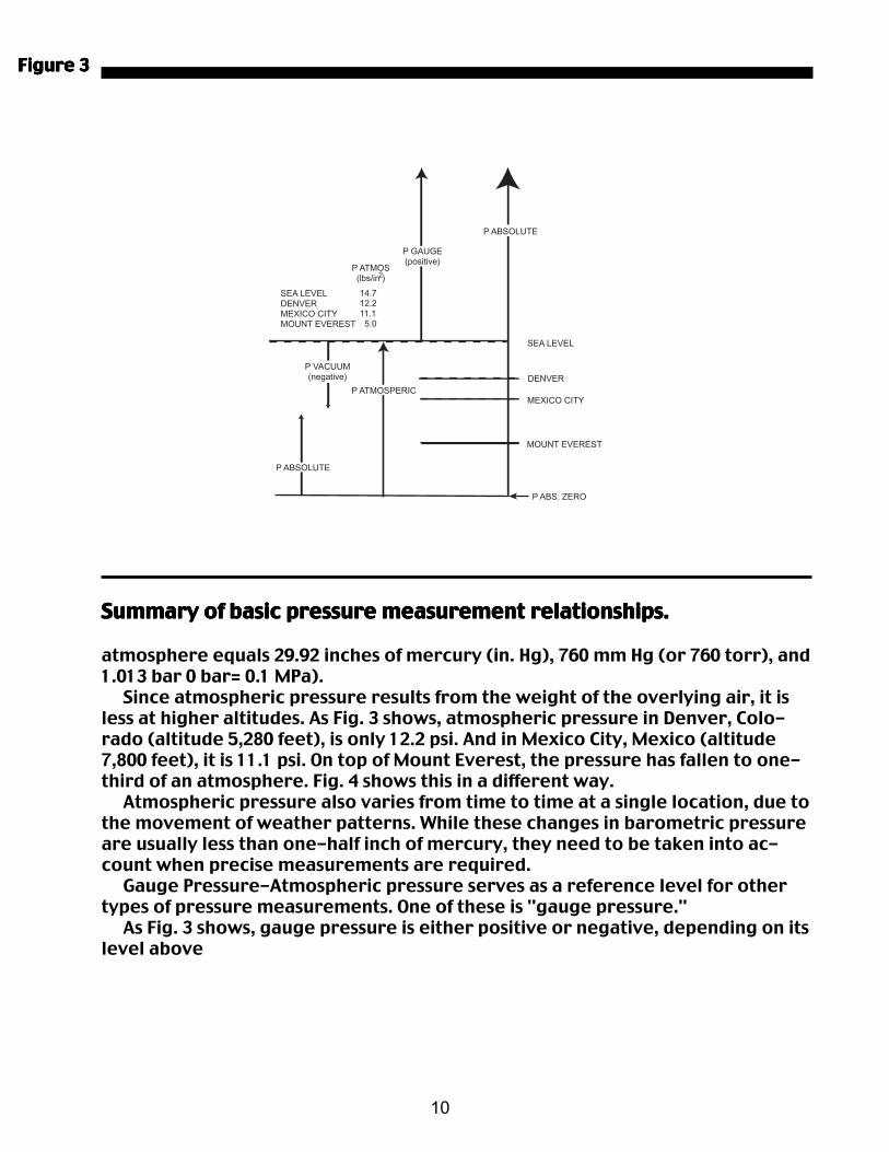
atmosphere equals 29.92 inches of mercury (in. Hg), 760 mm Hg (or 760 torr), and1.013 bar 0 bar= 0.1 MPa). Since atmospheric pressure results from the weight of the overlying air, it isless at higher altitudes. As Fig. 3 shows, atmospheric pressure in Denver, Colo-rado (altitude 5,280 feet), is only 12.2 psi. And in Mexico City, Mexico (altitude7,800 feet), it is 11.1 psi. On top of Mount Everest, the pressure has fallen to one-third of an atmosphere. Fig. 4 shows this in a different way. Atmospheric pressure also varies from time to time at a single location, due tothe movement of weather patterns. While these changes in barometric pressureare usually less than one-half inch of mercury, they need to be taken into ac-count when precise measurements are required. Gauge Pressure-Atmospheric pressure serves as a reference level for othertypes of pressure measurements. One of these is "gauge pressure." As Fig. 3 shows, gauge pressure is either positive or negative, depending on itslevel above
P ABSOLUTE
P GAUGE(positive)
SEA LEVELDENVERMEXICO CITYMOUNT EVEREST
SEA LEVEL
DENVERP ATMOSPERIC
P VACUUM(negative)
MEXICO CITY
MOUNT EVEREST
P ABS. ZERO
P ABSOLUTE
P ATMOS(lbs/in )2
14.712.211.1 5.0
11
Figure 4
Graph shows the effect of altitude on atmospheric pressure. Foreach thousand feet of elevation, atmospheric pressure In reducedby approximately 1 in. Hg.
or below the atmospheric pressure reference. For example, an ordinary tiregauge showing 30 pounds (actually, 30 psi) is showing the excess pressureabove atmospheric. In other words, what the gauge shows is the differencebetween atmospheric pressure and the pressure of the air pumped into thetire. Gauge pressures can be either positive (above atmospheric) or negative(below atmospheric). Atmospheric pressure represents zero gauge pressure.
Absolute Pressure Absolute Pressure Absolute Pressure Absolute Pressure Absolute Pressure - A different reference level is used to obtain a value for"absolute pressure." This is pressure measured above a perfect vacuum. It iscomposed of the sum of the gauge pressure (positive or negative) and theatmospheric pressure. Where there might be confusion, gauge and absolutepressures are distinguished by adding the letter "g" or "a," respectively, to theabbreviation for the units ("psig" or "psia").
12
Figure 5Figure 5Figure 5Figure 5Figure 5
To obtain the absolute pressure, simply add the value of atmospheric pressure(which averages 14.7 psi at sea level) to the gauge pressure reading. To find thecurrent value of atmospheric pressure in psia at a given location, multiply thebarometer reading in in. Hg by 0.491. This conversion factor arises from the factthat a cube of mercury with one inch sides weighs 0.491 pound and thus exerts apressure of 0.491 psi. Using the simple tire pressure example, the absolute pressure -including theatmospheric pressure-exerted by the air within the tire is 44.7 psia (30 psig plus14.7 psi). Thus, the absolute pressure is 14.7 psi more than would be read on atire-pressure gauge. Absolute pressure must be used in virtually all calculationsinvolving pressure ratios.
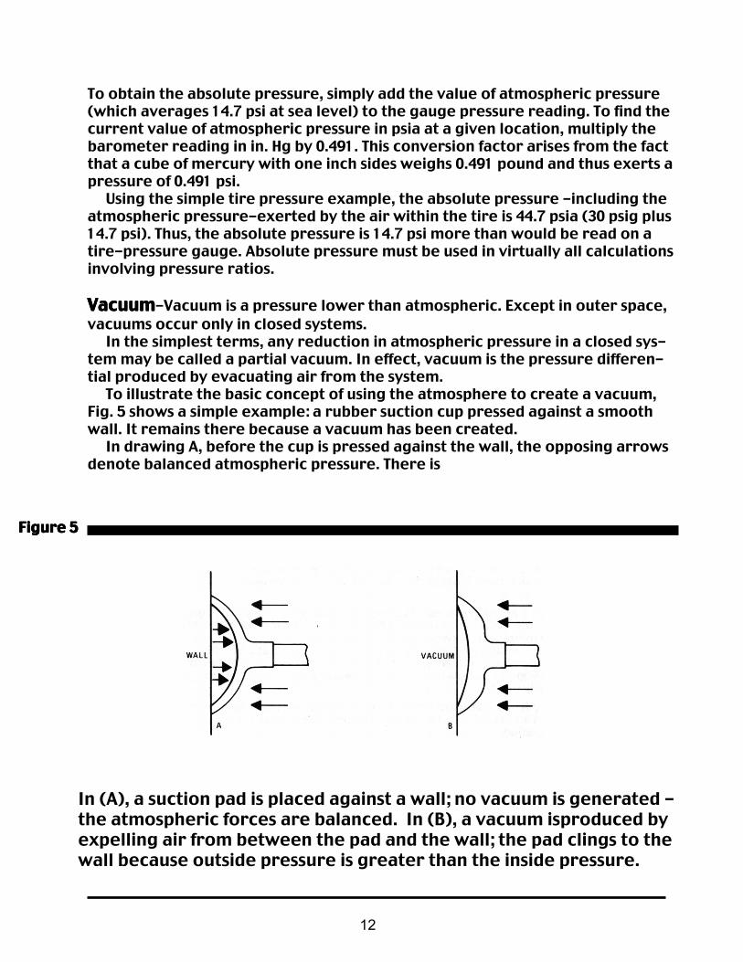
VacuumVacuumVacuumVacuumVacuum-Vacuum is a pressure lower than atmospheric. Except in outer space,vacuums occur only in closed systems. In the simplest terms, any reduction in atmospheric pressure in a closed sys-tem may be called a partial vacuum. In effect, vacuum is the pressure differen-tial produced by evacuating air from the system. To illustrate the basic concept of using the atmosphere to create a vacuum,Fig. 5 shows a simple example: a rubber suction cup pressed against a smoothwall. It remains there because a vacuum has been created. In drawing A, before the cup is pressed against the wall, the opposing arrowsdenote balanced atmospheric pressure. There is
In (A), a suction pad is placed against a wall; no vacuum is generated -the atmospheric forces are balanced. In (B), a vacuum isproduced byexpelling air from between the pad and the wall; the pad clings to thewall because outside pressure is greater than the inside pressure.
13
no vacuum yet because the air pressure inside the cup is equal to the air pres-sure outside. Both values are at atmospheric pressure. This balance changes when the cup is pressed against the wall. Drawing Bshows that a vacuum now exists in the remaining open space. After most of theair has been expelled, partial expansion of the cup leaves less air per unit vol-ume inside the cup than outside. With less thrust against the cup's inside surface,the pressures are now unbalanced. Outside atmospheric pressure forces the cupagainst the wall. And since pressure is also holding the edge of the cup firmly tothe wall, no air can leak in to relieve the partial vacuum inside. In a vacuum system more sophisticated than a suction cup, the enclosed spacewould be a valve actuator or some appropriate work device. A vacuum pumpwould be used to reduce atmospheric pressure in the closed space. The sameprinciple would apply, however. By removing air from one side of an air-tight barrier of some sort, atmo-spheric pressure can act against the other side. Just as with the suction cup, thisaction creates a pressure differential between the closed system and the openatmosphere. The pressure differential can be used to do work. For example, in liquid packaging (bottling), reducing the pressure in a bottle(the enclosed space) makes the filling operation go much faster because theliquid or other material is literally pulled into the bottle, rather than simplyfailing by gravity. Vacuum is usually divided into four levels:
Low vacuum Low vacuum Low vacuum Low vacuum Low vacuum represents pressures above one torr absolute. Flow in thisrange is viscous, as represented by most common fluids. Mechanical vacuumpumps are used for low vacuum, and represent the large majority of pumps inindustrial practice.
Medium vacuumMedium vacuumMedium vacuumMedium vacuumMedium vacuum represents pressures between 1 and 10 torr absolute. This isa transition range between viscous and molecular flow. Most pumps serving thisrange are also mechanical.
High vacuum High vacuum High vacuum High vacuum High vacuum represents pressures between 10-1 and 10-' torr absolute. Flowin this region is molecular or Newtonian, with very little interaction betweenindividual molecules. A number of specialized industrial applications, such as ionimplantation in the semiconductor industry, fall in this range. Nonmechanicalejector or cryogenic pumps (which are not discussed in this book) are usuallyused.
Very high vacuumVery high vacuumVery high vacuumVery high vacuumVery high vacuum represents absolute pressures below 10-1 torr. This isprimarily for laboratory applications and space simulation. Keep in mind that a "perfect" vacuum-that is, a space with no molecules oratoms-is a purely theoretical condition. Only in interstellar space is this condi-tion approached at all closely, and even there a few atoms per cubic meter willbe found. In practice, all vacuums are partial.

14
Units of Pressure/Vacuum Measurement
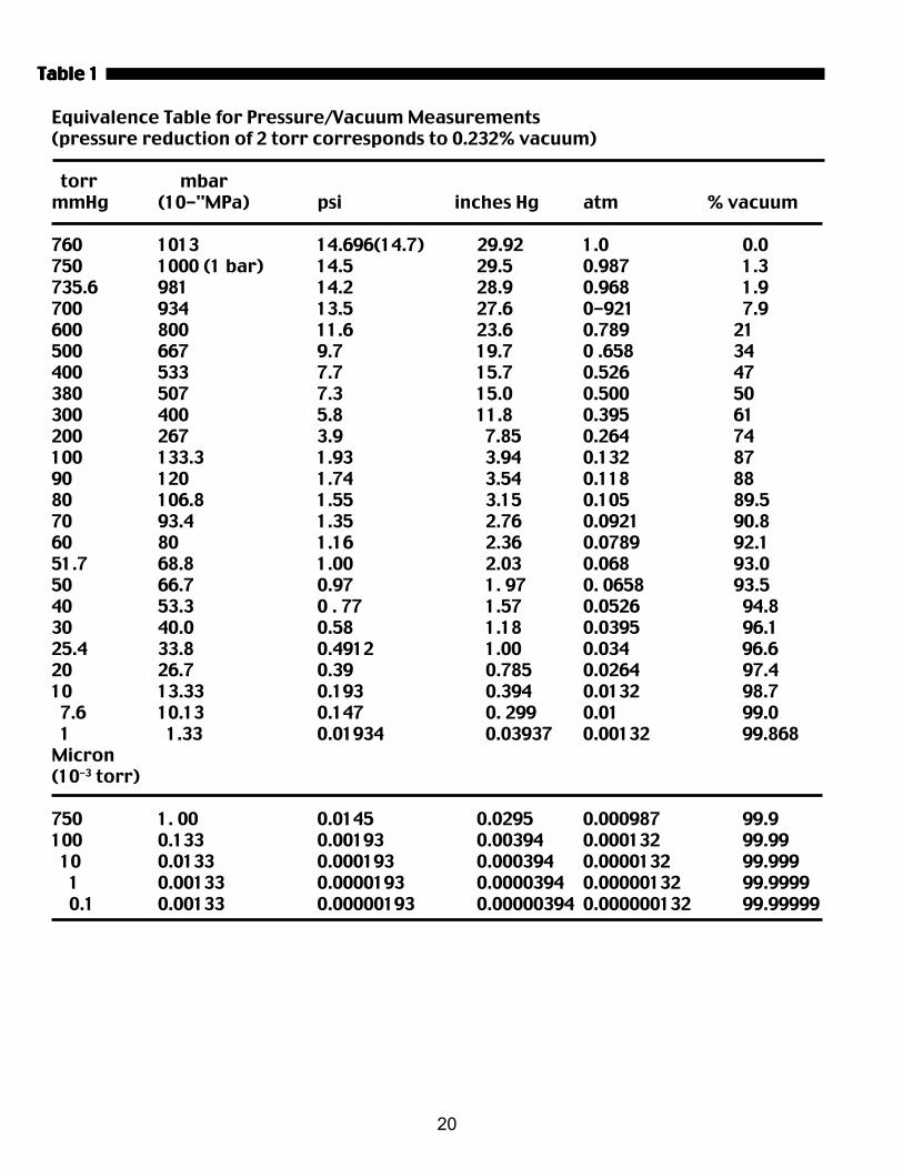
In the physical sciences, pressure is usually defined as the perpendicular forceper unit area, or the stress at a point within a confined fluid. This force per unitarea acting on a surface is expressed in metric units as Newtons per squaremeter (N/m2) or Pascals (Pa). The corresponding expression in the English sys-tem is pounds per square inch (psi); remember that the pound is a unit ofweight, or force, not of mass. However, many other units are still commonly used for pressure and vacuummeasurements. This is understandable because each offers specific advantagesin some instances. For example, "standard atmosphere" as a unit of measurement relatesdirectly to a physical feature of the Earth's surface (strictly speaking, only at sealevel). This feature may be the most prominent aspect of some situations. Andthe bar combines a value near one atmosphere with the simplicity of metricunits. It is defined as 105 Pascals. In some vacuum applications the most salient fact may be the fraction of airoriginally present that has been evacuated (percent vacuum). And whenmercury manometers were the usual instrument for vacuum/pressuremeasurements, the directly observable unit-requiring no further calculations-was the length of the mercury column in inches or millimeters. (Torr is themodern name for mm Hg.) Table 1 shows the equivalences for selected values of the common units.Other values can be calculated using the conversion factors: 1 atm = 14.70 psi 1 bar= 14.50 psi 1 MPa=145 psi 1 in. Hg = 0.4912 psi 1 in. H20 = 0.0361 psi 1 torr = 0.01934 psi
Measurement of Pressure and Vacuum
A number of devices are available to measure vacuum and pressure levels. Themost common are described here.
Absolute Pressure Gauge Absolute Pressure Gauge Absolute Pressure Gauge Absolute Pressure Gauge Absolute Pressure Gauge - As its name indicates, an absolute pressuregauge shows the pressure above a theoretical perfect vacuum condition. Itthusprovides an absolute reading. The most basic absolute pressure gauge is the barometer shown in Fig. 6. Thearrows denote atmospheric pressure acting on the surface of mercury in a dish.This pressure is transmitted in all directions within the body of mercury, includ-ing pressure upward into the tube. The height of the column supported this way directly measures the current atmospheric pressure. There is no inherent requirement that only atmospheric pressure bemeasured. When the apparatus is arranged so that some other pressure acts onthe mercury surface, that pressure can be measured equally well. It does not

15
A basic mercury barometer. The bottom of the tube is immersed in apool of mercury that is exposed to atmospheric pressure (arrows).This pushes the mercury up into the tube until the downward pres-sure of its weight is exactly equal to the pressure exerted by theatmosphere.
matter whether the pressure is above or below atmospheric; the only require-ment is that the tube be long enough to accommodate the mercury column. Another type of absolute pressure gauge is used for vacuum measurementsonly. This gauge (Fig. 7) has the same U shape as the manometer (next page), butleg A is sealed. Mercury fills this end when the gauge is not in use. When leg B is connected to a vacuum source, the mercury level in leg A ispulled down. The sliding scale is then placed so that the zero mark is oppositethe level in leg B. Matching the level in leg A against the scale then gives theabsolute pressure directly in in. Hg.
Mercury U-Tube Manometer - A manometer indicates the difference be-tween two pressures. If one is atmospheric pressure, the result is a direct read-ing of positive or negative gauge pressure. In its simplest form, the device is a U-tube about half-filled with mercury (Fig. 8)
Figure 6Figure 6Figure 6Figure 6Figure 6

16
Absolute pressure gauge (for vacuum only) uses a sliding scale tomeasure the difference in height between mercury in the two legs.Since the mercury completely fills the left-hand leg when the right-hand leg In connected to the atmosphere, the absolute pressure onthis leg Is always close to zero. Hence, the difference In height of thetwo legs measures the absolute pressure (in In. Hg) on the right-hand leg.
With both ends of the tube open to the atmosphere, the liquid is at the sameheight in each leg. This is a zero value because the atmospheric pressure isequal and has balanced the two columns. But when a vacuum source is applied to one leg, the mercury rises in that legand falls in the other leg. The total difference, h (2 + 2 = 4 in this instance), inheight between the two new levels is the gauge pressure-in this case, negative. Had a positive pressure been applied to the left leg, then the mercury wouldhave fallen there and risen in the right leg. Again, the total difference in heightbetween the two new levels would represent the gauge pressure.
Plunger GaugePlunger GaugePlunger GaugePlunger GaugePlunger Gauge-A plunger gauge consists of a plunger connected to systempressure, a bias spring, and a calibrated indicator. An auto tire gauge would bean example.
Figure 7Figure 7Figure 7Figure 7Figure 7

17
Mercury U-tube manometer. With the right-hand log connected tothe atmosphere, the difference in height of the two legs measuresthe gauge pressure (in In. Hg) on the left-hand leg.
As pressure in the system rises, it moves the plunger against the force ex-erted by the bias spring. This movement also moves the indicator to show theappropriate pressure on the scale. With suitable calibration and a spring that can work in extension as well ascompression, a plunger gauge can be used for either positive or negative pres-sure.
Bourdon GaugeBourdon GaugeBourdon GaugeBourdon GaugeBourdon Gauge-This is the most widely used instrument for measuring bothpositive pressure and vacuum. Measurement is based on the deformation of anelastic element (a curved tube) by the pressure being measured. The radius ofcurvature increases with increasing positive pressure and decreases with in-creasing vacuum. The resulting deflection is indicated by a pointer on a cali-brated dial through a ratchet linkage. Similar gauges may be based on the deformation of diaphragms or otherflexible barriers.
McLeod GaugeMcLeod GaugeMcLeod GaugeMcLeod GaugeMcLeod Gauge-For extremely accurate measurements of very low pressures(high vacuums), the McLeod vacuum gauge is the most widely used device. It'salso used to calibrate other types of gauges. This design uses Boyle's Law (see below) to determine pressure in a system. Asample of the gas is isolated in the gauge and reduced in volume by a knownamount. This causes a proportional increase in pressure, which, in turn, pro-duces a readable difference in the height of a mercury column. The McLeod gauge is rarely used for industrial applications. It is better suitedto laboratory studies where very high vacuums are involved.
Figure 8Figure 8Figure 8Figure 8Figure 8
18
Pressure/Volume/ Temperature Relationships
Pressure, volume, and temperature are basic measurable properties of air. Theyare not completely independent properties but are interrelated in specific,simple ways. When designing a pneumatic system, it is helpful to understandthese relationships.
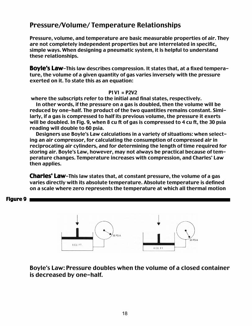
Boyle's LawBoyle's LawBoyle's LawBoyle's LawBoyle's Law-This law describes compression. It states that, at a fixed tempera-ture, the volume of a given quantity of gas varies inversely with the pressureexerted on it. To state this as an equation:
P1V1 = P2V2 where the subscripts refer to the initial and final states, respectively. In other words, if the pressure on a gas is doubled, then the volume will bereduced by one-half. The product of the two quantities remains constant. Simi-larly, if a gas is compressed to half its previous volume, the pressure it exertswill be doubled. In Fig. 9, when 8 cu ft of gas is compressed to 4 cu ft, the 30 psiareading will double to 60 psia. Designers use Boyle's Law calculations in a variety of situations: when select-ing an air compressor, for calculating the consumption of compressed air inreciprocating air cylinders, and for determining the length of time required forstoring air. Boyle's Law, however, may not always be practical because of tem-perature changes. Temperature increases with compression, and Charles' Lawthen applies.
Charles' LawCharles' LawCharles' LawCharles' LawCharles' Law-This law states that, at constant pressure, the volume of a gasvaries directly with its absolute temperature. Absolute temperature is definedon a scale where zero represents the temperature at which all thermal motion
Boyle's Law: Pressure doubles when the volume of a closed containeris decreased by one-half.
Figure 9Figure 9Figure 9Figure 9Figure 9
19
Figure 10Figure 10Figure 10Figure 10Figure 10
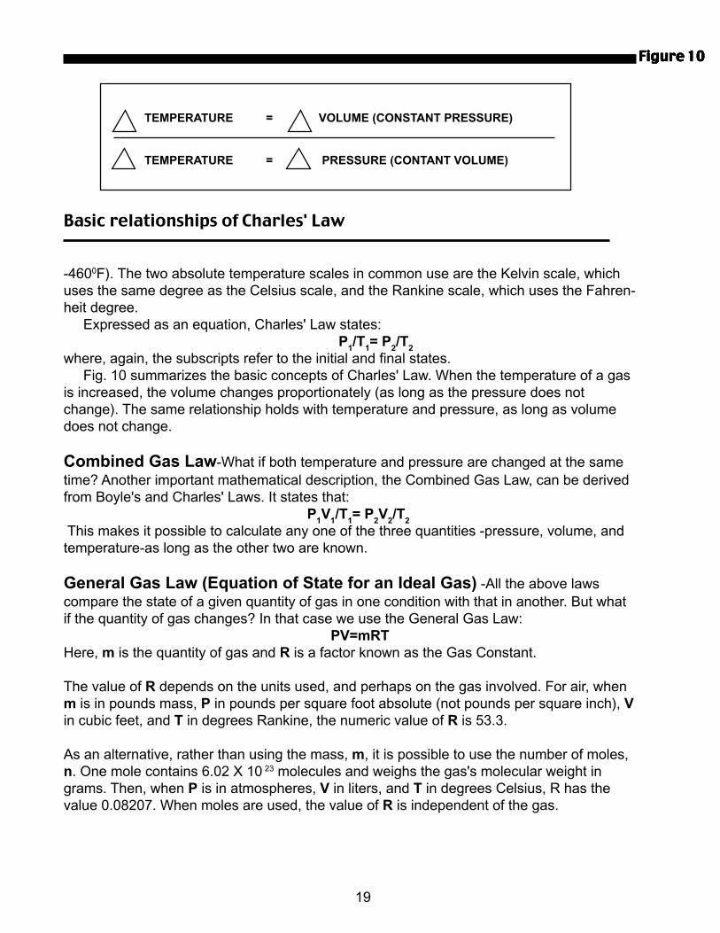
Basic relationships of Charles' Law
-4600F). The two absolute temperature scales in common use are the Kelvin scale, whichuses the same degree as the Celsius scale, and the Rankine scale, which uses the Fahren-heit degree. Expressed as an equation, Charles' Law states: P
1/T
1= P
2/T
2
where, again, the subscripts refer to the initial and final states. Fig. 10 summarizes the basic concepts of Charles' Law. When the temperature of a gasis increased, the volume changes proportionately (as long as the pressure does notchange). The same relationship holds with temperature and pressure, as long as volumedoes not change.
Combined Gas Law-What if both temperature and pressure are changed at the sametime? Another important mathematical description, the Combined Gas Law, can be derivedfrom Boyle's and Charles' Laws. It states that: P
1V
1/T
1= P
2V
2/T
2
This makes it possible to calculate any one of the three quantities -pressure, volume, andtemperature-as long as the other two are known.
General Gas Law (Equation of State for an Ideal Gas) -All the above lawscompare the state of a given quantity of gas in one condition with that in another. But whatif the quantity of gas changes? In that case we use the General Gas Law: PV=mRTHere, m is the quantity of gas and R is a factor known as the Gas Constant.
The value of R depends on the units used, and perhaps on the gas involved. For air, whenm is in pounds mass, P in pounds per square foot absolute (not pounds per square inch), Vin cubic feet, and T in degrees Rankine, the numeric value of R is 53.3.
As an alternative, rather than using the mass, m, it is possible to use the number of moles,n. One mole contains 6.02 X 10 23 molecules and weighs the gas's molecular weight ingrams. Then, when P is in atmospheres, V in liters, and T in degrees Celsius, R has thevalue 0.08207. When moles are used, the value of R is independent of the gas.
TEMPERATURE = VOLUME (CONSTANT PRESSURE)
TEMPERATURE = PRESSURE (CONTANT VOLUME)
20
Equivalence Table for Pressure/Vacuum Measurements(pressure reduction of 2 torr corresponds to 0.232% vacuum)
torr mbarmmHg (10-"MPa) psi inches Hg atm % vacuum
760 1013 14.696(14.7) 29.92 1.0 0.0750 1000 (1 bar) 14.5 29.5 0.987 1.3735.6 981 14.2 28.9 0.968 1.9700 934 13.5 27.6 0-921 7.9600 800 11.6 23.6 0.789 21500 667 9.7 19.7 0 .658 34400 533 7.7 15.7 0.526 47380 507 7.3 15.0 0.500 50300 400 5.8 11.8 0.395 61200 267 3.9 7.85 0.264 74100 133.3 1.93 3.94 0.132 8790 120 1.74 3.54 0.118 8880 106.8 1.55 3.15 0.105 89.570 93.4 1.35 2.76 0.0921 90.860 80 1.16 2.36 0.0789 92.151.7 68.8 1.00 2.03 0.068 93.050 66.7 0.97 1. 97 0. 0658 93.540 53.3 0 . 77 1.57 0.0526 94.830 40.0 0.58 1.18 0.0395 96.125.4 33.8 0.4912 1.00 0.034 96.620 26.7 0.39 0.785 0.0264 97.410 13.33 0.193 0.394 0.0132 98.7 7.6 10.13 0.147 0. 299 0.01 99.0 1 1.33 0.01934 0.03937 0.00132 99.868Micron(10-3 torr)
750 1. 00 0.0145 0.0295 0.000987 99.9100 0.133 0.00193 0.00394 0.000132 99.99 10 0.0133 0.000193 0.000394 0.0000132 99.999 1 0.00133 0.0000193 0.0000394 0.00000132 99.9999 0.1 0.00133 0.00000193 0.00000394 0.000000132 99.99999
Table 1Table 1Table 1Table 1Table 1


