Embed Size (px)
Citation preview
VP-8-V2 and VP-16-V2 Series Encoder
User Manual
VP-8-V2 and VP-16-V2 Series Encoder·User Manual
1
About this Manual
This Manual is applicable to VP-8-V2 AND VP-16-V2 Series Encoder.
The Manual includes instructions for using and managing the product. Pictures, charts, images
and all other information hereinafter are for description and explanation only. The information
contained in the Manual is subject to change, without notice, due to firmware updates or other
reasons. Please find the latest version in the company website
Please use this user manual under the guidance of professionals.
Legal Disclaimer
REGARDING TO THE PRODUCT WITH INTERNET ACCESS, THE USE OF PRODUCT SHALL BE WHOLLY
AT YOUR OWN RISKS. OUR COMPANY SHALL NOT TAKE ANY RESPONSIBILITES FOR ABNORMAL
OPERATION, PRIVACY LEAKAGE OR OTHER DAMAGES RESULTING FROM CYBER ATTACK, HACKER
ATTACK, VIRUS INSPECTION, OR OTHER INTERNET SECURITY RISKS; HOWEVER, OUR COMPANY
WILL PROVIDE TIMELY TECHNICAL SUPPORT IF REQUIRED.
SURVEILLANCE LAWS VARY BY JURISDICTION. PLEASE CHECK ALL RELEVANT LAWS IN YOUR
JURISDICTION BEFORE USING THIS PRODUCT IN ORDER TO ENSURE THAT YOUR USE CONFORMS
THE APPLICABLE LAW. OUR COMPANY SHALL NOT BE LIABLE IN THE EVENT THAT THIS PRODUCT
IS USED WITH ILLEGITIMATE PURPOSES.
IN THE EVENT OF ANY CONFLICTS BETWEEN THIS MANUAL AND THE APPLICABLE LAW, THE
LATER PREVAILS.
VP-8-V2 and VP-16-V2 Series Encoder·User Manual
2
Regulatory Information
FCC Information
FCC compliance: This equipment has been tested and found to comply with the limits for a Class
A digital device, pursuant to part 15 of the FCC Rules. These limits are designed to provide
reasonable protection against harmful interference when the equipment is operated in a
commercial environment. This equipment generates, uses, and can radiate radio frequency
energy and, if not installed and used in accordance with the instruction manual, may cause
harmful interference to radio communications. Operation of this equipment in a residential area
is likely to cause harmful interference in which case the user will be required to correct the
interference at his own expense.
FCC Conditions
This device complies with part 15 of the FCC Rules. Operation is subject to the following two
conditions:
1. This device may not cause harmful interference.
2. This device must accept any interference received, including interference that may cause
undesired operation.
EU Conformity Statement
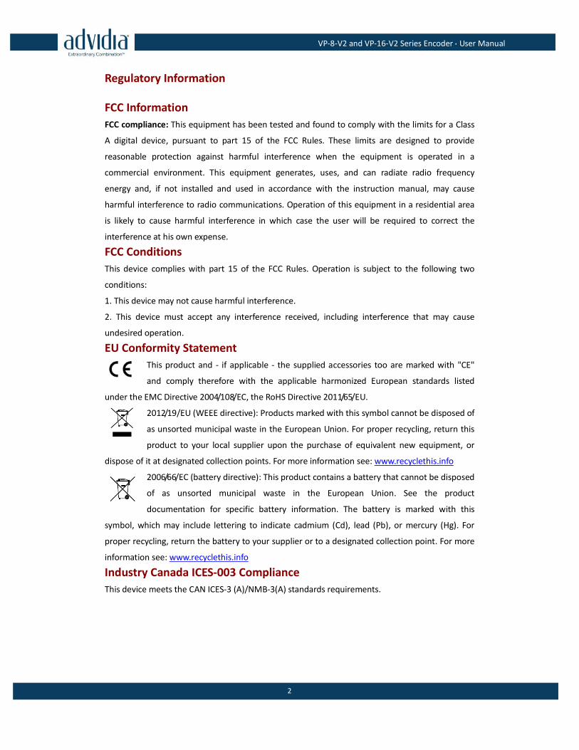
This product and - if applicable - the supplied accessories too are marked with "CE"
and comply therefore with the applicable harmonized European standards listed
under the EMC Directive 2004/108/EC, the RoHS Directive 2011/65/EU.
2012/19/EU (WEEE directive): Products marked with this symbol cannot be disposed of
as unsorted municipal waste in the European Union. For proper recycling, return this
product to your local supplier upon the purchase of equivalent new equipment, or
dispose of it at designated collection points. For more information see: www.recyclethis.info
2006/66/EC (battery directive): This product contains a battery that cannot be disposed
of as unsorted municipal waste in the European Union. See the product
documentation for specific battery information. The battery is marked with this
symbol, which may include lettering to indicate cadmium (Cd), lead (Pb), or mercury (Hg). For
proper recycling, return the battery to your supplier or to a designated collection point. For more
information see: www.recyclethis.info
Industry Canada ICES-003 Compliance
This device meets the CAN ICES-3 (A)/NMB-3(A) standards requirements.
VP-8-V2 and VP-16-V2 Series Encoder·User Manual
3
Safety Instruction
These instructions are intended to ensure that user can use the product correctly to avoid danger
or property loss.
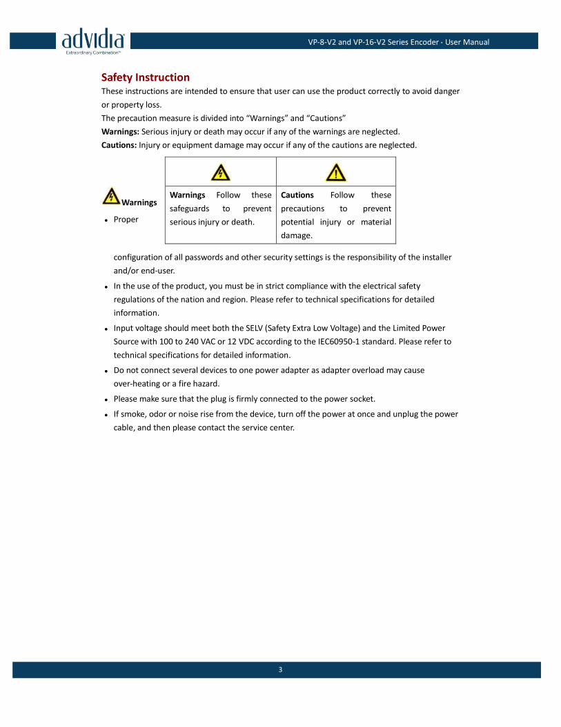
The precaution measure is divided into “Warnings” and “Cautions”
Warnings: Serious injury or death may occur if any of the warnings are neglected.
Cautions: Injury or equipment damage may occur if any of the cautions are neglected.
Warnings
● Proper
configuration of all passwords and other security settings is the responsibility of the installer
and/or end-user.
● In the use of the product, you must be in strict compliance with the electrical safety
regulations of the nation and region. Please refer to technical specifications for detailed
information.
● Input voltage should meet both the SELV (Safety Extra Low Voltage) and the Limited Power
Source with 100 to 240 VAC or 12 VDC according to the IEC60950-1 standard. Please refer to
technical specifications for detailed information.
● Do not connect several devices to one power adapter as adapter overload may cause
over-heating or a fire hazard.
● Please make sure that the plug is firmly connected to the power socket.
● If smoke, odor or noise rise from the device, turn off the power at once and unplug the power
cable, and then please contact the service center.
Warnings Follow these
safeguards to prevent
serious injury or death.
Cautions Follow these
precautions to prevent
potential injury or material
damage.
VP-8-V2 and VP-16-V2 Series Encoder·User Manual
4
Preventive and Cautionary Tips
Before connecting and operating your device, please be advised of the following tips:
• Ensure unit is installed in a well-ventilated, dust-free environment.
• Unit is designed for indoor use only.
• Keep all liquids away from the device.
• Ensure environmental conditions meet factory specifications.
• Ensure unit is properly secured to a rack or shelf. Major shocks or jolts to the unit as a result
of dropping it may cause damage to the sensitive electronics within the unit.
• Use the device in conjunction with an UPS if possible.
• Power down the unit before connecting and disconnecting accessories and peripherals.
• Improper use or replacement of the battery may result in hazard of explosion. Replace with
the same or equivalent type only. Dispose of used batteries according to the instructions
provided by the battery manufacturer.
VP-8-V2 and VP-16-V2 Series Encoder·User Manual
5
TABLE OF CONTENTS Product Key Features......................................................................................................................................... 7
Chapter 1 Introduction ........................................................................................................................... 8
1.1 Front Panel ...................................................................................................................................... 8
1.2 Rear Panel ........................................................................................................................................ 8
1.3 Alarm Connections .......................................................................................................................... 9
1.3.1 Alarm Input Connections ..................................................................................................... 9
1.3.2 Alarm Output Connections ................................................................................................ 10
Chapter 2 Access to V2 Encoder via Web Browser .............................................................................. 11
2.1 Installing Web Components ........................................................................................................... 11
2.2 Main Page ...................................................................................................................................... 13
Chapter 3 Live View .............................................................................................................................. 15
3.1 Starting Live View .......................................................................................................................... 15
3.1.1 Main/Sub Stream Live View ............................................................................................... 16
3.1.2 Full-screen Mode ............................................................................................................... 16
3.2 Capturing the Picture..................................................................................................................... 17
3.3 Operating PTZ Control ................................................................................................................... 17
3.3.3 Operating PTZ Movement .................................................................................................. 17
3.3.4 Setting/Calling a Preset ...................................................................................................... 18
3.3.5 Setting/Calling a Patrol....................................................................................................... 20
3.4 Configuring Video Parameters ....................................................................................................... 21
Chapter 4 Device Configuration ........................................................................................................... 23
4.1 Local Configuration ........................................................................................................................ 23
4.2 Device Parameters ......................................................................................................................... 24
4.2.1 Configuring Time Settings .................................................................................................. 24
4.2.2 Configuring Packet Time of Recording ............................................................................... 26
4.3 Network Settings ........................................................................................................................... 26
4.3.1 Configuring TCP/IP Settings ................................................................................................ 26
4.3.2 Configuring Port Settings ................................................................................................... 27
4.3.3 Configuring DDNS Settings ................................................................................................. 28
4.3.4 Configuring PPPoE Settings ................................................................................................ 29
4.3.5 Configuring Email Settings ................................................................................................. 30
4.3.6 Configuring SNMP Settings ................................................................................................ 32
4.3.7 Configuring UPnPTM Settings .............................................................................................. 33
4.3.8 Configuring HTTPS Settings ................................................................................................ 34
4.3.9 Configuring Multicast Address ........................................................................................... 36
4.3.10 Configuring Remote Alarm Host ........................................................................................ 36
Chapter 5 Camera Settings ................................................................................................................... 38
5.1 Configuring OSD Settings ............................................................................................................... 38
5.1.1 Configuring Display Settings ............................................................................................... 38
5.1.2 Configuring Text Overlay .................................................................................................... 39
5.2 Configuring Video Settings ............................................................................................................ 41
VP-8-V2 and VP-16-V2 Series Encoder·User Manual
6
5.3 Configuring and Handling Alarms .................................................................................................. 42
5.3.3 Configuring Motion Detection ........................................................................................... 42
5.3.4 Configuring External Alarm Input ....................................................................................... 48
5.3.5 Configuring Video Loss Alarm ............................................................................................ 49
5.3.6 Configuring Video Tempering Alarm .................................................................................. 50
5.3.7 Handling Exception ............................................................................................................ 51
5.4 Configuring Privacy Mask .............................................................................................................. 52
Chapter 6 Managing User Accounts ..................................................................................................... 54
1.1 Adding a User ................................................................................................................................ 54
6.2 Modifying a User ........................................................................................................................... 55
6.3 Deleting a User .............................................................................................................................. 56
Chapter 7 Maintenance ........................................................................................................................ 58
7.1 Viewing Device Information .......................................................................................................... 58
7.2 Maintenance.................................................................................................................................. 58
7.2.1 Restarting the Device ......................................................................................................... 59
7.2.2 Restoring Default Settings .................................................................................................. 59
7.2.3 Importing/Exporting Configuration Files ........................................................................... 60
7.2.4 Upgrading the System ........................................................................................................ 60
Chapter 8 Specification ........................................................................................................................ 61
FAQ………………………………………………………………………………………………………………………………………………………62
VP-8-V2 and VP-16-V2 Series Encoder·User Manual
7
Product Key Features
General
Connectable to HD-TVI and analog cameras
Connectable to the Coax camera/dome with long transmission distance
Each channel supports dual-stream with up to 1080p resolution
Independent configuration for each channel, including resolution, frame rate, bit rate, image
quality, etc
Encoding for both video stream and video and audio stream; audio and video
synchronization during composite stream encoding
Watermark technology
Monitoring
Motion detection, video-tampering detection, video exception alarm, video loss alarm and
VCA alarm functions
Privacy mask
Several PTZ protocols supported; PTZ preset, patrol and pattern
Alarm and Exception
Configurable arming time of alarm input/output
Alarm triggers, audio alarm, notifying surveillance center, sending email and alarm output
VCA detection alarm (line crossing detection and intrusion detection) is supported by client
software
Support coaxial alarm.
Network Functions
1 self-adaptive 10M/100M/1000M network interface
IPv6 is supported
TCP/IP protocol, PPPoE, DHCP, DNS, DDNS, NTP, SADP, SMTP, SNMP, NFS, iSCSI, UPnP™ and
HTTPS are supported
Extranet access by HiDDNS
TCP, UDP and RTP for unicast
Auto/Manual port mapping by UPnPTM
Remote search, playback, download, locking and unlocking the record files, and
downloading files broken transfer resume
Remote parameters setup; remote import/export of device parameters
Remote viewing of the device status, system logs and alarm status
Remote keyboard operation
Remote program upgrading
Remote system restart and shutdown
Alarm and exception information can be sent to the remote host
VP-8-V2 and VP-16-V2 Series Encoder·User Manual
8
Remotely start/stop recording
Remotely start/stop alarm output
Remote PTZ control
Remote JPEG capture
Two-way audio and voice broadcasting
Embedded WEB server
Chapter 1 Introduction
1.1 Front Panel
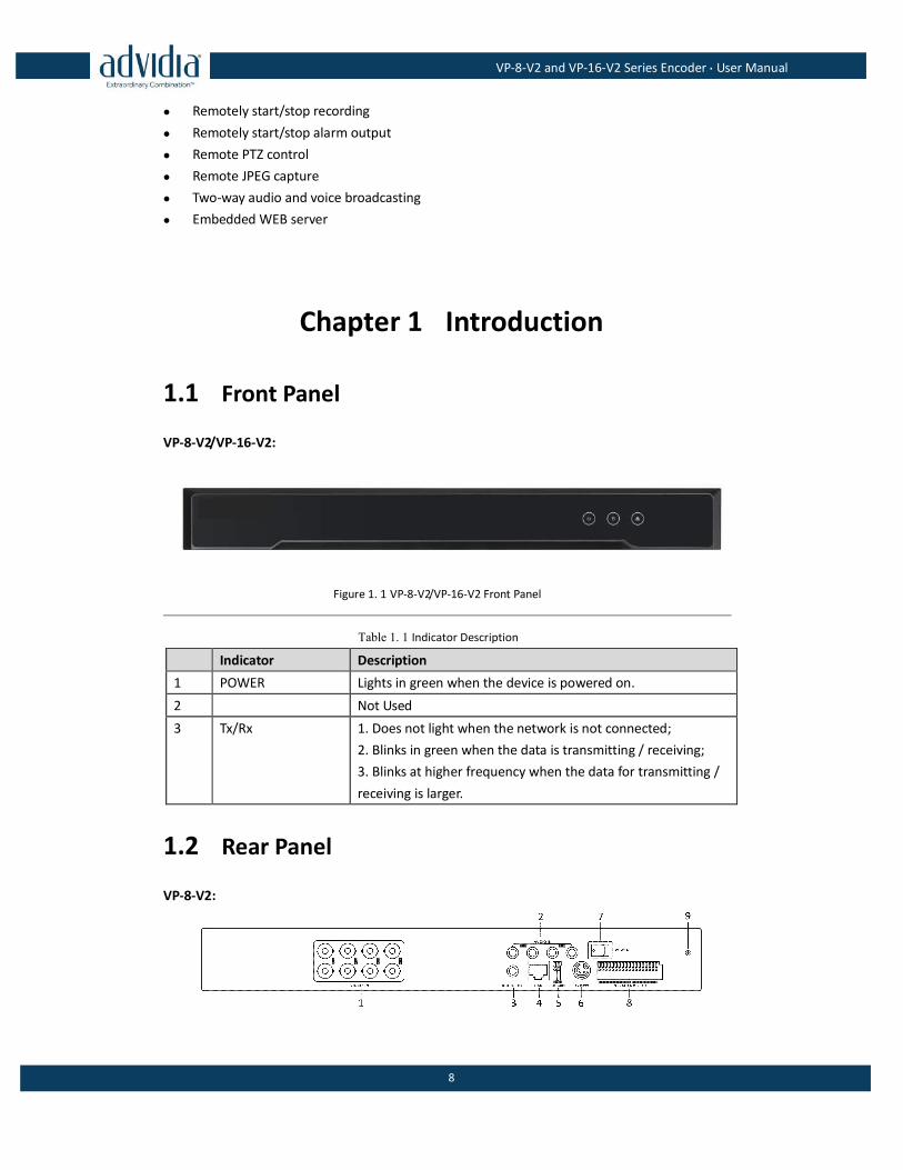
VP-8-V2/VP-16-V2:
Figure 1. 1 VP-8-V2/VP-16-V2 Front Panel
Table 1. 1 Indicator Description
Indicator Description
1 POWER Lights in green when the device is powered on.
2 Not Used
3 Tx/Rx 1. Does not light when the network is not connected;
2. Blinks in green when the data is transmitting / receiving;
3. Blinks at higher frequency when the data for transmitting /
receiving is larger.
1.2 Rear Panel
VP-8-V2:
VP-8-V2 and VP-16-V2 Series Encoder·User Manual
9
Figure 1. 2 VP-8-V2 Rear Panel
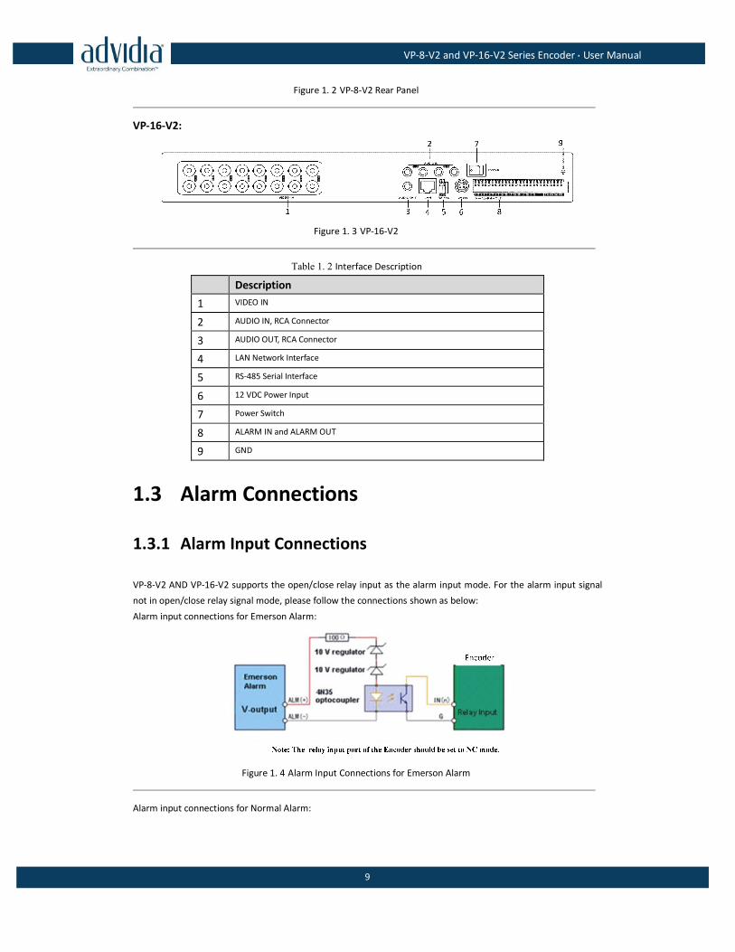
VP-16-V2:
Figure 1. 3 VP-16-V2
Table 1. 2 Interface Description
Description
1 VIDEO IN
2 AUDIO IN, RCA Connector
3 AUDIO OUT, RCA Connector
4 LAN Network Interface
5 RS-485 Serial Interface
6 12 VDC Power Input
7 Power Switch
8 ALARM IN and ALARM OUT
9 GND
1.3 Alarm Connections
1.3.1 Alarm Input Connections
VP-8-V2 AND VP-16-V2 supports the open/close relay input as the alarm input mode. For the alarm input signal
not in open/close relay signal mode, please follow the connections shown as below:
Alarm input connections for Emerson Alarm:
Figure 1. 4 Alarm Input Connections for Emerson Alarm
Alarm input connections for Normal Alarm:
VP-8-V2 and VP-16-V2 Series Encoder·User Manual
10
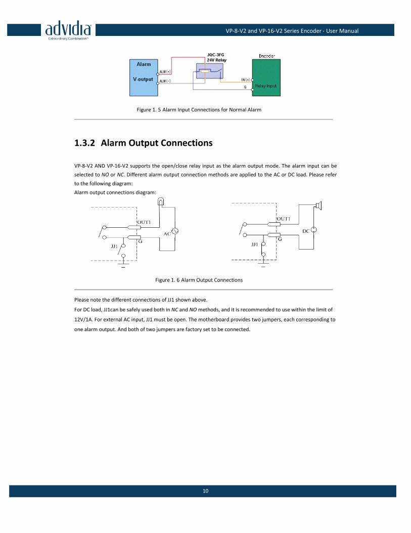
Figure 1. 5 Alarm Input Connections for Normal Alarm
1.3.2 Alarm Output Connections
VP-8-V2 AND VP-16-V2 supports the open/close relay input as the alarm output mode. The alarm input can be
selected to NO or NC. Different alarm output connection methods are applied to the AC or DC load. Please refer
to the following diagram:
Alarm output connections diagram:
Figure 1. 6 Alarm Output Connections
Please note the different connections of JJ1 shown above.
For DC load, JJ1can be safely used both in NC and NO methods, and it is recommended to use within the limit of
12V/1A. For external AC input, JJ1 must be open. The motherboard provides two jumpers, each corresponding to
one alarm output. And both of two jumpers are factory set to be connected.
VP-8-V2 and VP-16-V2 Series Encoder·User Manual
11
Chapter 2 Access to V2 Encoder via Web
Browser
Steps:
1. Power on the encoder, and connect the encoder to the network.
2. Input the IP address into the address bar of the web browser, and click Enter to enter the activation
interface.
The default IP address of the network encoder is 192.0.0.64. You are recommended to change
the default IP address after your access.
3. Default username is admin Default password is 12345.
The VP-8-V2 AND VP-16-V2 can also be accessed by WEB Browser for configuration and operation. The supported
WEB browsers include: Internet Explorer 6/7/8/9, Firefox 3.5 and above, Chrome 8 and above, Safari 5.0.2 and
above, Windows XP SP1 and above (32-bit).
Before you start:
Before access, you need to configure the network settings of device according to Chapter 3.
Connect the device to the LAN, and prepare a PC connected to the same LAN with the device.
The factory default IP address of the device is 192.0.0.64.
2.1 Installing Web Components
Steps:
1. Open WEB browser, input the IP address of VP-8-V2 AND VP-16-V2 (e.g., http://192.0.0.64) and then press
the Enter key on PC. The system will display the login interface.
When the HTTPS feature is enabled, the system uses the HTTPS login mode (e.g., https://192.0.0.64) by default.
You can also input http://IP address/index.asp (e.g., http://192.0.0.64/index.asp) if you want to use HTTP mode to
log into the device.
VP-8-V2 and VP-16-V2 Series Encoder·User Manual
12
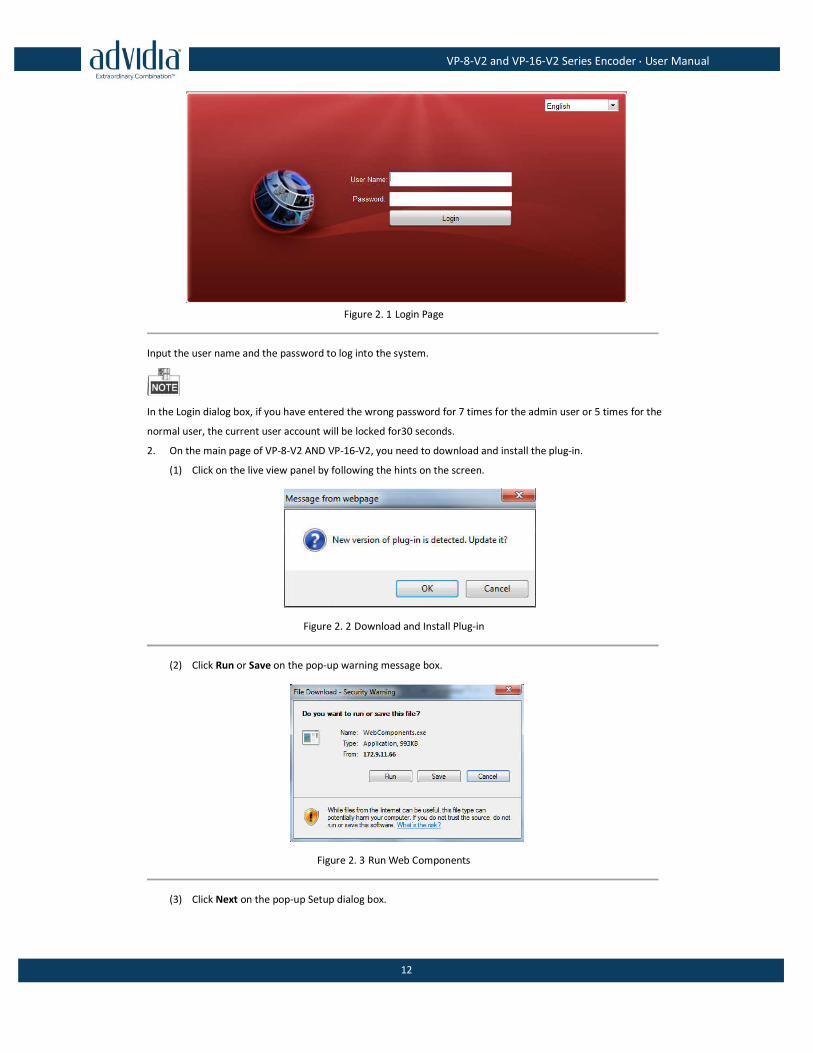
Figure 2. 1 Login Page
Input the user name and the password to log into the system.
In the Login dialog box, if you have entered the wrong password for 7 times for the admin user or 5 times for the
normal user, the current user account will be locked for30 seconds.
2. On the main page of VP-8-V2 AND VP-16-V2, you need to download and install the plug-in.
(1) Click on the live view panel by following the hints on the screen.
Figure 2. 2 Download and Install Plug-in
(2) Click Run or Save on the pop-up warning message box.
Figure 2. 3 Run Web Components
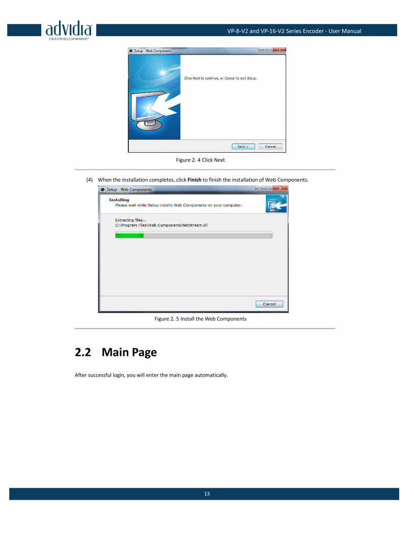
(3) Click Next on the pop-up Setup dialog box.
VP-8-V2 and VP-16-V2 Series Encoder·User Manual
13
Figure 2. 4 Click Next
(4) When the installation completes, click Finish to finish the installation of Web Components.
Figure 2. 5 Install the Web Components
2.2 Main Page
After successful login, you will enter the main page automatically.
VP-8-V2 and VP-16-V2 Series Encoder·User Manual
14
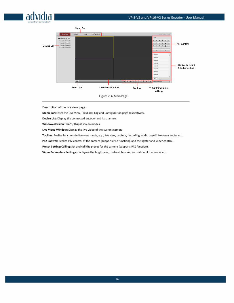
Figure 2. 6 Main Page
Description of the live view page:
Menu Bar: Enter the Live View, Playback, Log and Configuration page respectively.
Device List: Display the connected encoder and its channels.
Window-division: 1/4/9/16split screen modes.
Live Video Window: Display the live video of the current camera.
Toolbar: Realize functions in live view mode, e.g., live view, capture, recording, audio on/off, two-way audio, etc.
PTZ Control: Realize PTZ control of the camera (supports PTZ function), and the lighter and wiper control.
Preset Setting/Calling: Set and call the preset for the camera (supports PTZ function).
Video Parameters Settings: Configure the brightness, contrast, hue and saturation of the live video.
VP-8-V2 and VP-16-V2 Series Encoder·User Manual
15
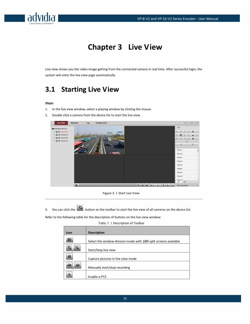
Chapter 3 Live View
Live view shows you the video image getting from the connected camera in real time. After successful login, the
system will enter the live view page automatically.
3.1 Starting Live View
Steps:
1. In the live view window, select a playing window by clicking the mouse.
2. Double click a camera from the device list to start the live view.
Figure 3. 1 Start Live View
3. You can click the button on the toolbar to start the live view of all cameras on the device list.
Refer to the following table for the description of buttons on the live view window:
Table 3. 1 Description of Toolbar
Icon Description
Select the window-division mode with 1/4/9 split screens available
/ Start/Stop live view
Capture pictures in live view mode
/ Manually start/stop recording
Enable e-PTZ
VP-8-V2 and VP-16-V2 Series Encoder·User Manual
16
Previous page
Icon Description
Next page
/ Audio on/off
/ Start/Stop two-way audio
Switch to full-screen live view mode.
Before using two-way audio function or recording with audio, please select the Video Type to Video & Audio on
Section Configuring Video Settings.
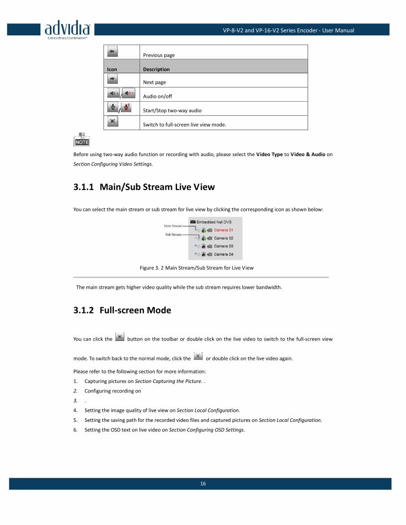
3.1.1 Main/Sub Stream Live View
You can select the main stream or sub stream for live view by clicking the corresponding icon as shown below:
Figure 3. 2 Main Stream/Sub Stream for Live View
The main stream gets higher video quality while the sub stream requires lower bandwidth.
3.1.2 Full-screen Mode
You can click the button on the toolbar or double click on the live video to switch to the full-screen view
mode. To switch back to the normal mode, click the or double click on the live video again.
Please refer to the following section for more information:
1. Capturing pictures on Section Capturing the Picture. .
2. Configuring recording on
3. .
4. Setting the image quality of live view on Section Local Configuration.
5. Setting the saving path for the recorded video files and captured pictures on Section Local Configuration.
6. Setting the OSD text on live video on Section Configuring OSD Settings.
VP-8-V2 and VP-16-V2 Series Encoder·User Manual
17
3.2 Capturing the Picture
In live view mode, click the button on the toolbar to capture the live pictures.
When the picture is captured, the following pop-up message box will appear at the lower right corner.
Figure 3. 3 Picture Capture Succeeded
The saving path for the captured pictures can be set at the Configuration > Local Configuration page.
The image is saved as a JPEG file on your computer.
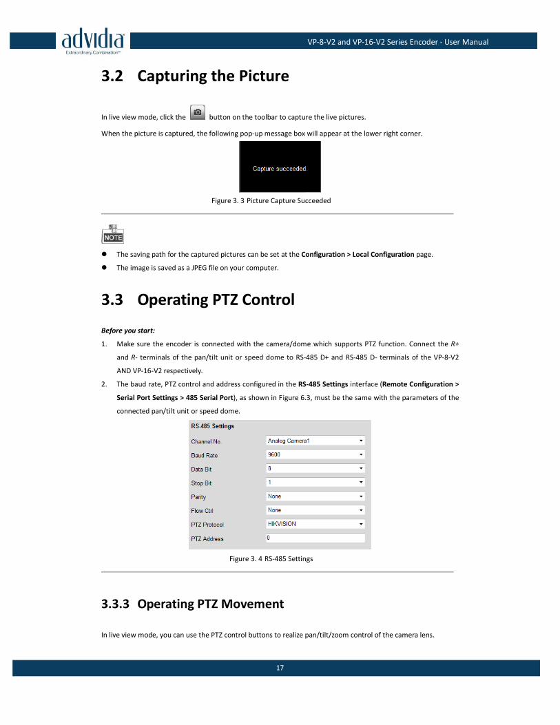
3.3 Operating PTZ Control
Before you start:
1. Make sure the encoder is connected with the camera/dome which supports PTZ function. Connect the R+
and R- terminals of the pan/tilt unit or speed dome to RS-485 D+ and RS-485 D- terminals of the VP-8-V2
AND VP-16-V2 respectively.
2. The baud rate, PTZ control and address configured in the RS-485 Settings interface (Remote Configuration >
Serial Port Settings > 485 Serial Port), as shown in Figure 6.3, must be the same with the parameters of the
connected pan/tilt unit or speed dome.
Figure 3. 4 RS-485 Settings
3.3.3 Operating PTZ Movement
In live view mode, you can use the PTZ control buttons to realize pan/tilt/zoom control of the camera lens.
VP-8-V2 and VP-16-V2 Series Encoder·User Manual
18
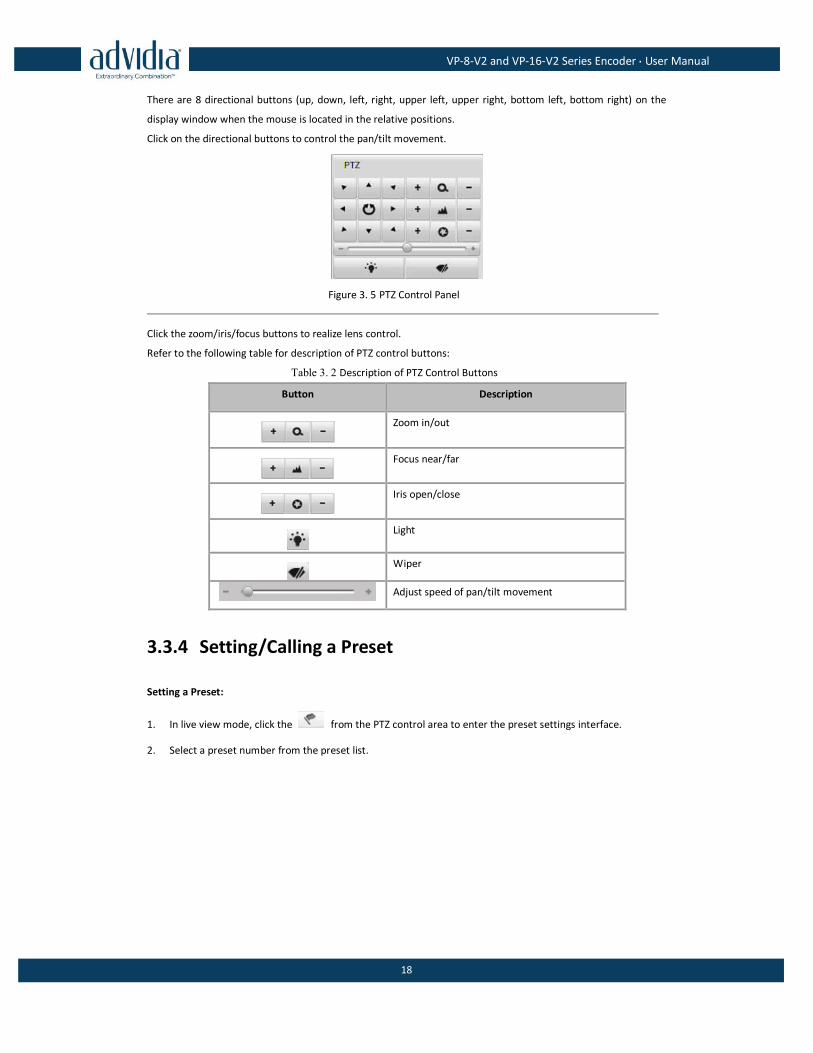
There are 8 directional buttons (up, down, left, right, upper left, upper right, bottom left, bottom right) on the
display window when the mouse is located in the relative positions.
Click on the directional buttons to control the pan/tilt movement.
Figure 3. 5 PTZ Control Panel
Click the zoom/iris/focus buttons to realize lens control.
Refer to the following table for description of PTZ control buttons:
Table 3. 2 Description of PTZ Control Buttons
Button Description
Zoom in/out
Focus near/far
Iris open/close
Light
Wiper
Adjust speed of pan/tilt movement
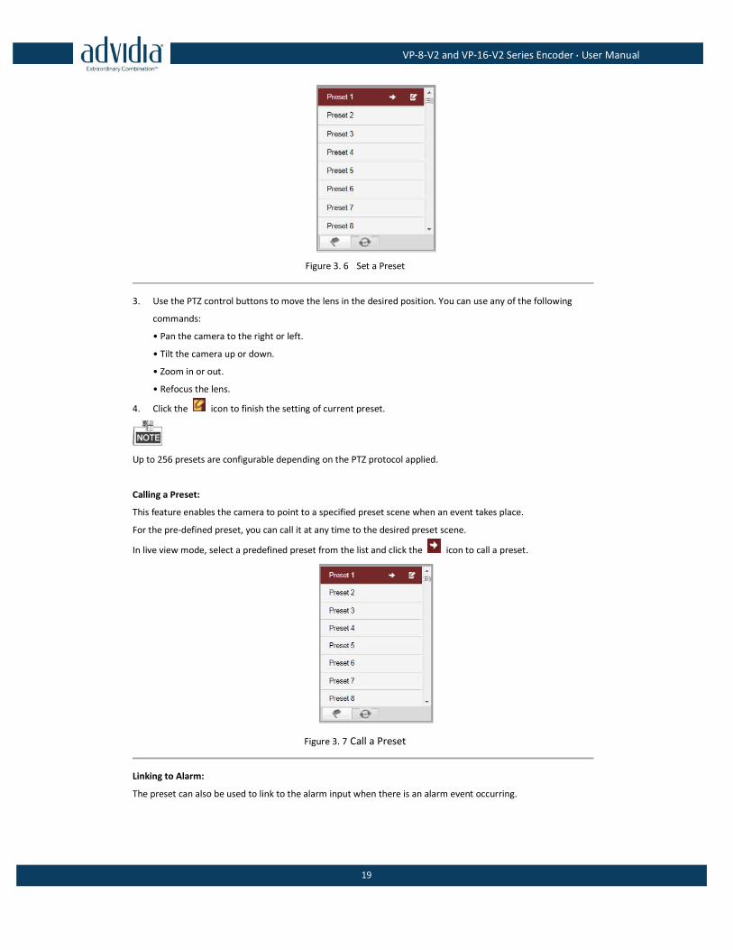
3.3.4 Setting/Calling a Preset
Setting a Preset:
1. In live view mode, click the from the PTZ control area to enter the preset settings interface.
2. Select a preset number from the preset list.
VP-8-V2 and VP-16-V2 Series Encoder·User Manual
19
Figure 3. 6 Set a Preset
3. Use the PTZ control buttons to move the lens in the desired position. You can use any of the following
commands:
• Pan the camera to the right or left.
• Tilt the camera up or down.
• Zoom in or out.
• Refocus the lens.
4. Click the icon to finish the setting of current preset.
Up to 256 presets are configurable depending on the PTZ protocol applied.
Calling a Preset:
This feature enables the camera to point to a specified preset scene when an event takes place.
For the pre-defined preset, you can call it at any time to the desired preset scene.
In live view mode, select a predefined preset from the list and click the icon to call a preset.
Figure 3. 7 Call a Preset
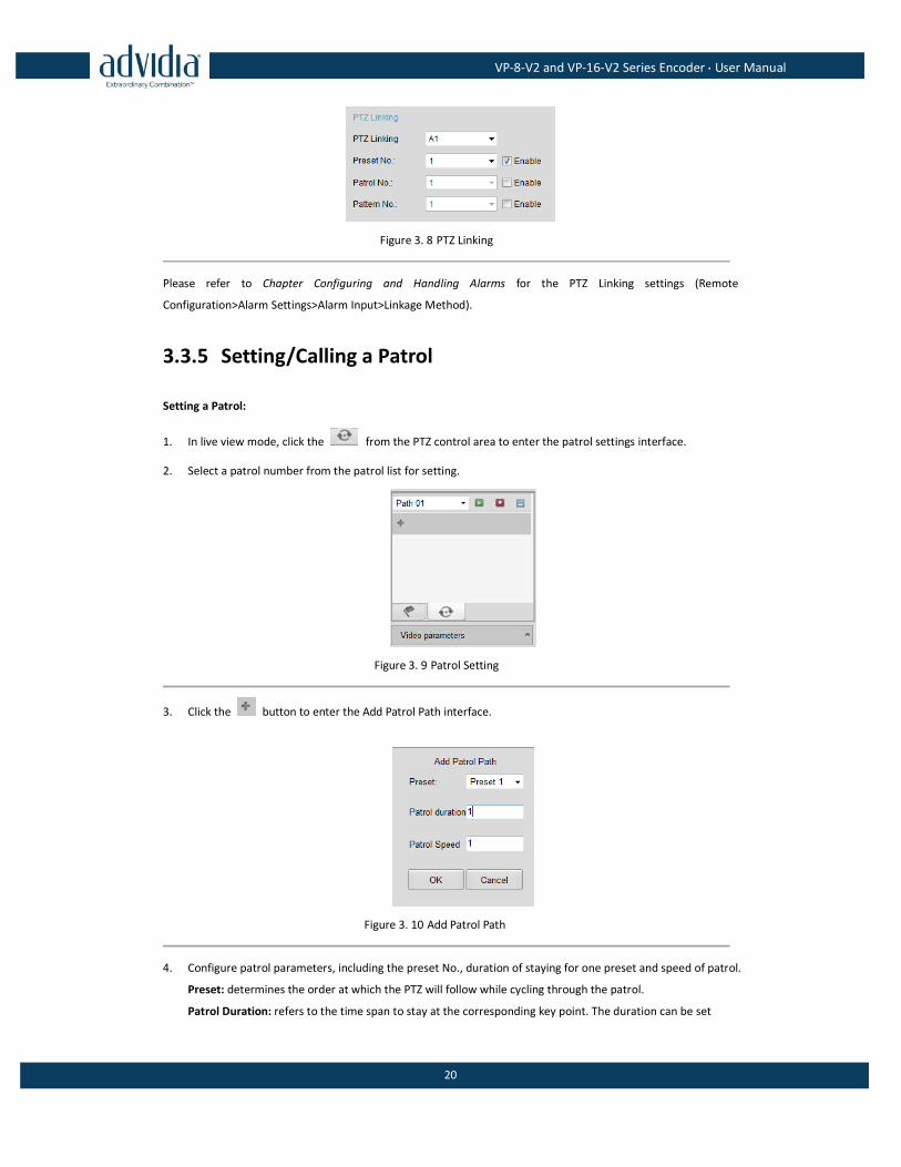
Linking to Alarm:
The preset can also be used to link to the alarm input when there is an alarm event occurring.
VP-8-V2 and VP-16-V2 Series Encoder·User Manual
20
Figure 3. 8 PTZ Linking
Please refer to Chapter Configuring and Handling Alarms for the PTZ Linking settings (Remote
Configuration>Alarm Settings>Alarm Input>Linkage Method).
3.3.5 Setting/Calling a Patrol
Setting a Patrol:
1. In live view mode, click the from the PTZ control area to enter the patrol settings interface.
2. Select a patrol number from the patrol list for setting.
Figure 3. 9 Patrol Setting
3. Click the button to enter the Add Patrol Path interface.
Figure 3. 10 Add Patrol Path
4. Configure patrol parameters, including the preset No., duration of staying for one preset and speed of patrol.
Preset: determines the order at which the PTZ will follow while cycling through the patrol.
Patrol Duration: refers to the time span to stay at the corresponding key point. The duration can be set
VP-8-V2 and VP-16-V2 Series Encoder·User Manual
21
from 1 to 30 sec.
Patrol Speed: defines the speed at which the PTZ will move from one key point to the next. The speed can
be set from 1 to 40.
Hold the backspace in the keyboard while changing the number in the text fields of Patrol Duration and
Patrol Speed.
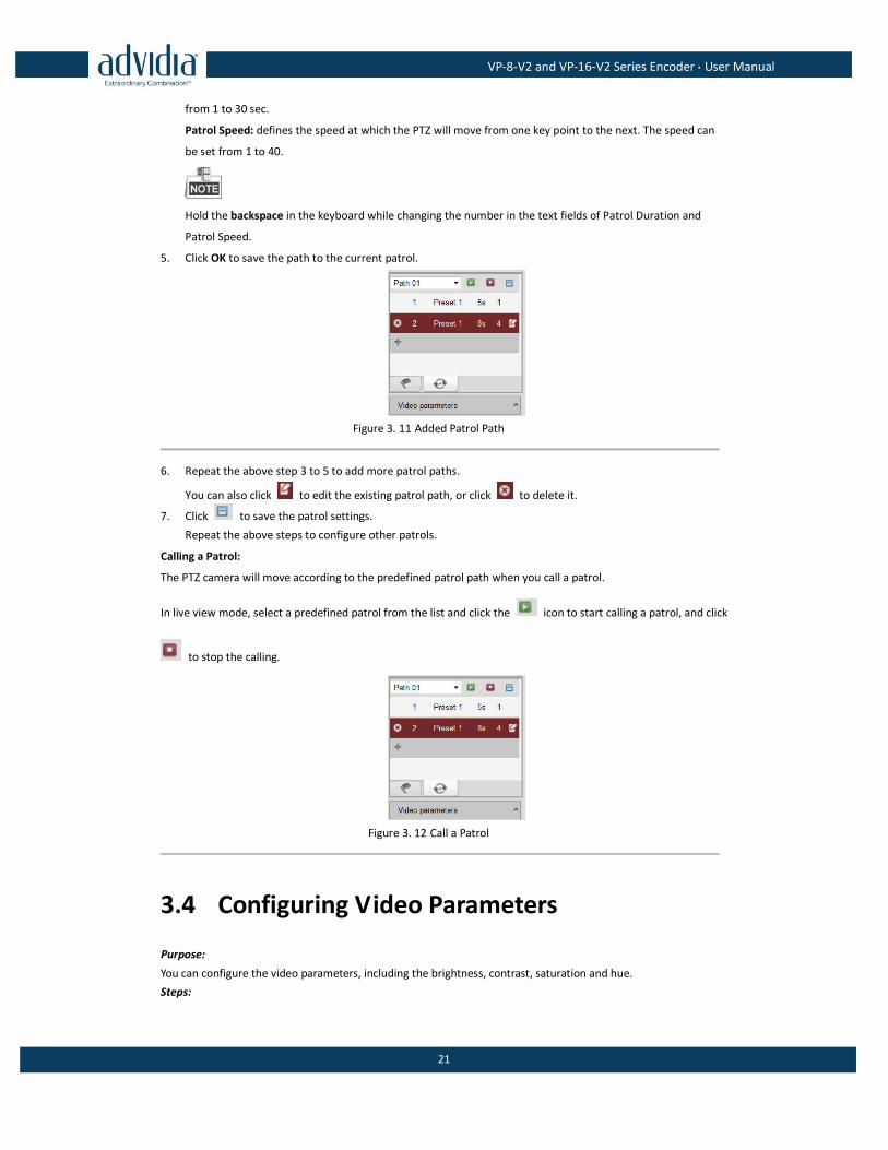
5. Click OK to save the path to the current patrol.
Figure 3. 11 Added Patrol Path
6. Repeat the above step 3 to 5 to add more patrol paths.
You can also click to edit the existing patrol path, or click to delete it.
7. Click to save the patrol settings.
Repeat the above steps to configure other patrols.
Calling a Patrol:
The PTZ camera will move according to the predefined patrol path when you call a patrol.
In live view mode, select a predefined patrol from the list and click the icon to start calling a patrol, and click
to stop the calling.
Figure 3. 12 Call a Patrol
3.4 Configuring Video Parameters
Purpose:
You can configure the video parameters, including the brightness, contrast, saturation and hue.
Steps:
VP-8-V2 and VP-16-V2 Series Encoder·User Manual
22
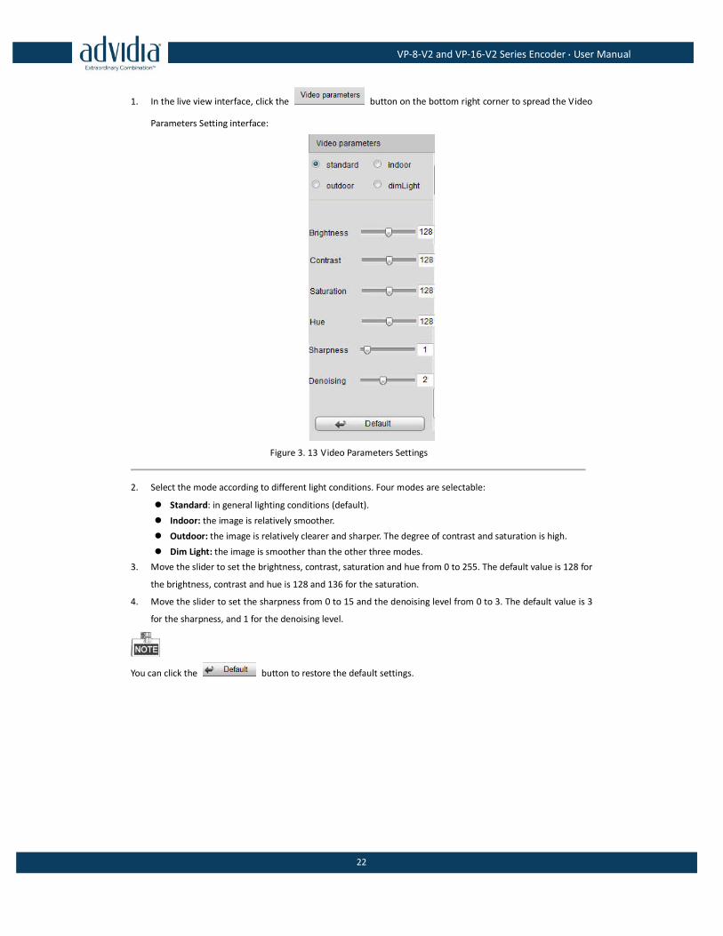
1. In the live view interface, click the button on the bottom right corner to spread the Video
Parameters Setting interface:
Figure 3. 13 Video Parameters Settings
2. Select the mode according to different light conditions. Four modes are selectable:
Standard: in general lighting conditions (default).
Indoor: the image is relatively smoother.
Outdoor: the image is relatively clearer and sharper. The degree of contrast and saturation is high.
Dim Light: the image is smoother than the other three modes.
3. Move the slider to set the brightness, contrast, saturation and hue from 0 to 255. The default value is 128 for
the brightness, contrast and hue is 128 and 136 for the saturation.
4. Move the slider to set the sharpness from 0 to 15 and the denoising level from 0 to 3. The default value is 3
for the sharpness, and 1 for the denoising level.
You can click the button to restore the default settings.
VP-8-V2 and VP-16-V2 Series Encoder·User Manual
23
Chapter 4 Device Configuration
4.1 Local Configuration
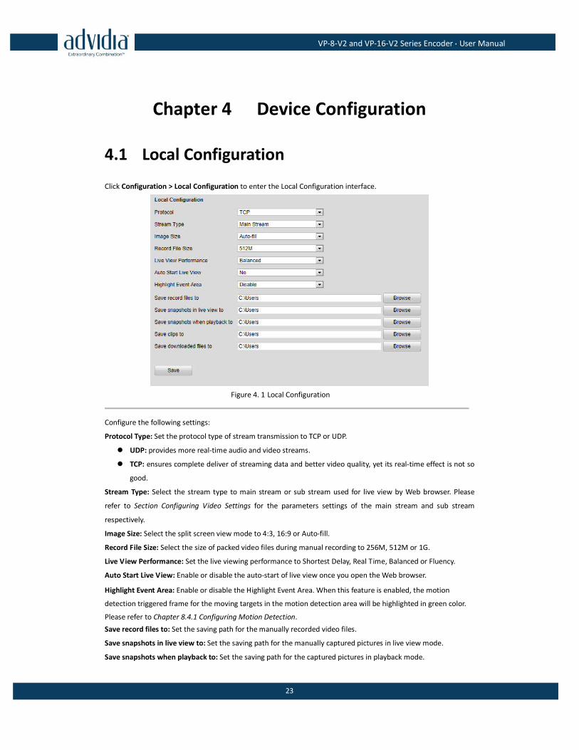
Click Configuration > Local Configuration to enter the Local Configuration interface.
Figure 4. 1 Local Configuration
Configure the following settings:
Protocol Type: Set the protocol type of stream transmission to TCP or UDP.
UDP: provides more real-time audio and video streams.
TCP: ensures complete deliver of streaming data and better video quality, yet its real-time effect is not so
good.
Stream Type: Select the stream type to main stream or sub stream used for live view by Web browser. Please
refer to Section Configuring Video Settings for the parameters settings of the main stream and sub stream
respectively.
Image Size: Select the split screen view mode to 4:3, 16:9 or Auto-fill.
Record File Size: Select the size of packed video files during manual recording to 256M, 512M or 1G.
Live View Performance: Set the live viewing performance to Shortest Delay, Real Time, Balanced or Fluency.
Auto Start Live View: Enable or disable the auto-start of live view once you open the Web browser.
Highlight Event Area: Enable or disable the Highlight Event Area. When this feature is enabled, the motion
detection triggered frame for the moving targets in the motion detection area will be highlighted in green color.
Please refer to Chapter 8.4.1 Configuring Motion Detection.
Save record files to: Set the saving path for the manually recorded video files.
Save snapshots in live view to: Set the saving path for the manually captured pictures in live view mode.
Save snapshots when playback to: Set the saving path for the captured pictures in playback mode.
VP-8-V2 and VP-16-V2 Series Encoder·User Manual
24
Save clips to: Set the saving path for the clipped video files in playback mode.
Save downloaded files to: Set the saving path for the downloaded video files or pictures.
You can click the Browse button to change the directory for saving the video files and pictures.
4.2 Device Parameters
4.2.1 Configuring Time Settings
Steps:
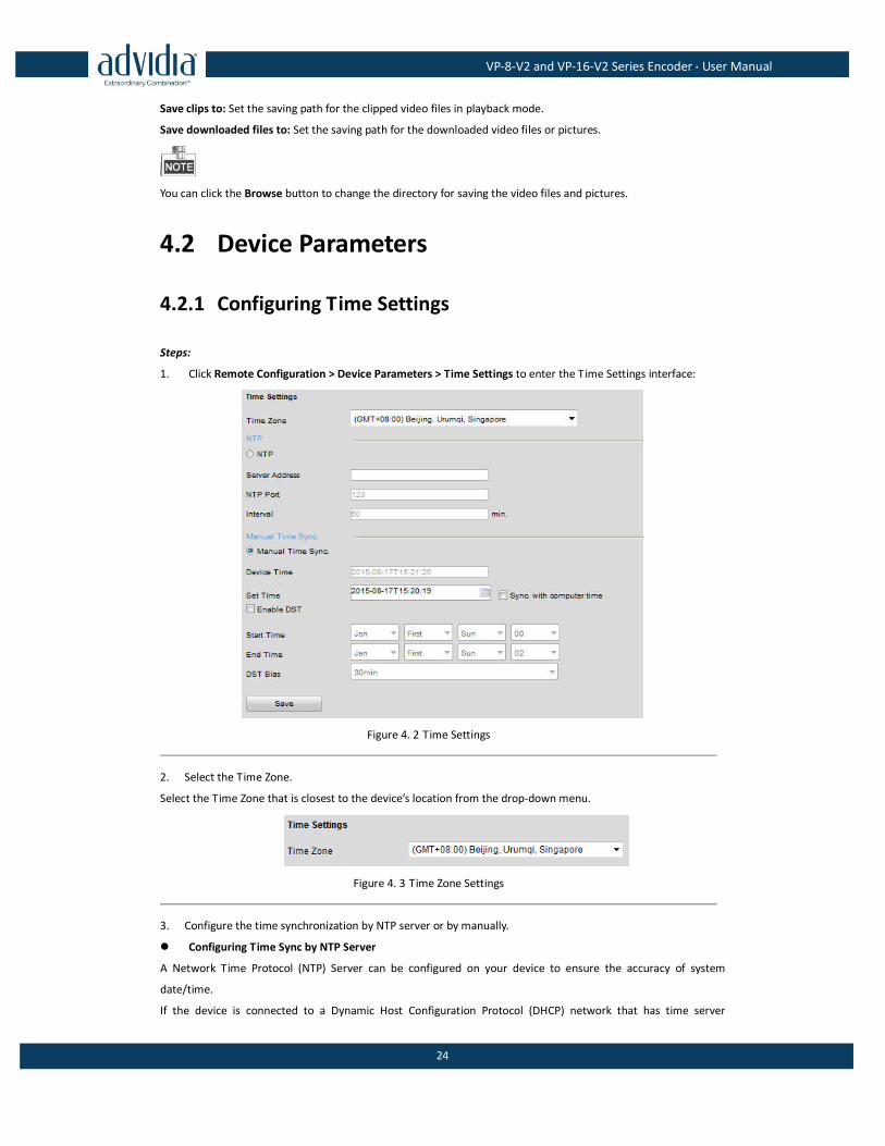
1. Click Remote Configuration > Device Parameters > Time Settings to enter the Time Settings interface:
Figure 4. 2 Time Settings
2. Select the Time Zone.
Select the Time Zone that is closest to the device’s location from the drop-down menu.
Figure 4. 3 Time Zone Settings
3. Configure the time synchronization by NTP server or by manually.
Configuring Time Sync by NTP Server
A Network Time Protocol (NTP) Server can be configured on your device to ensure the accuracy of system
date/time.
If the device is connected to a Dynamic Host Configuration Protocol (DHCP) network that has time server
VP-8-V2 and VP-16-V2 Series Encoder·User Manual
25
properties configured, the camera will synchronize automatically with the time server.
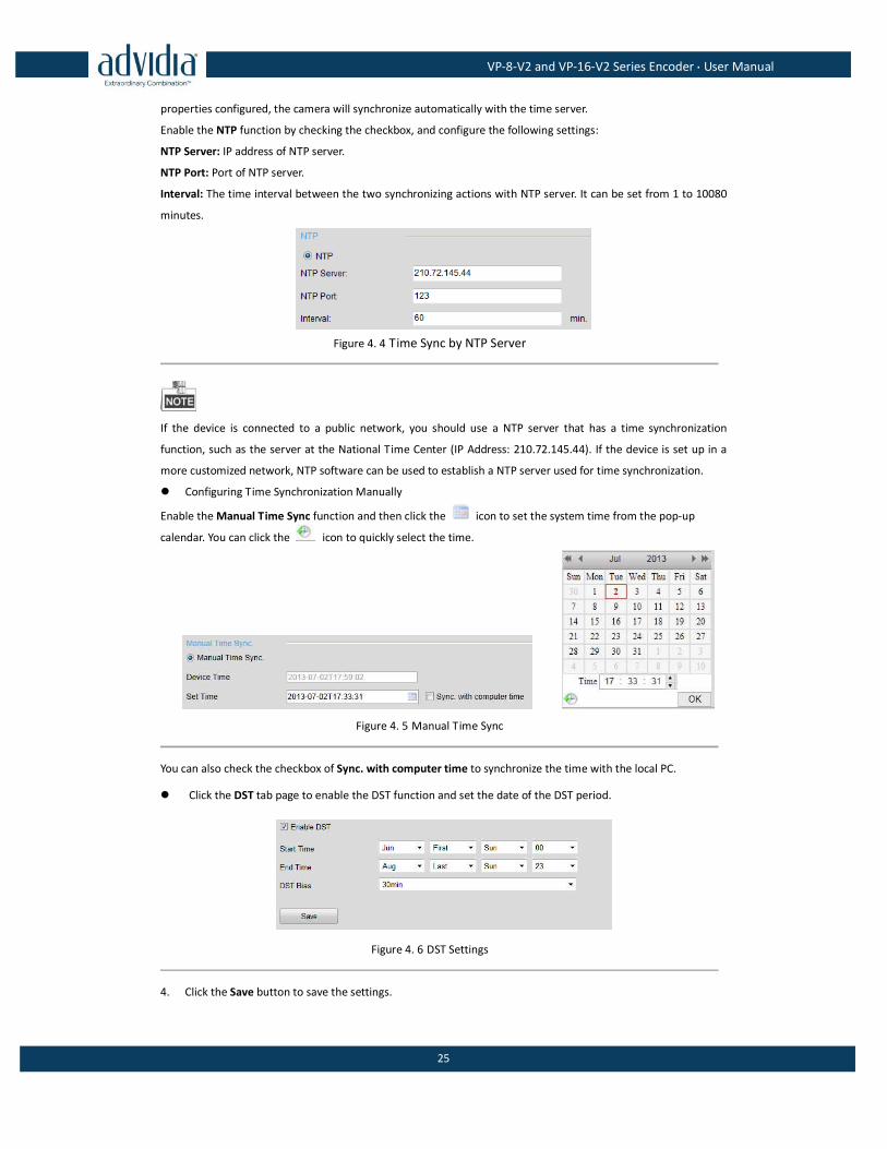
Enable the NTP function by checking the checkbox, and configure the following settings:
NTP Server: IP address of NTP server.
NTP Port: Port of NTP server.
Interval: The time interval between the two synchronizing actions with NTP server. It can be set from 1 to 10080
minutes.
Figure 4. 4 Time Sync by NTP Server
If the device is connected to a public network, you should use a NTP server that has a time synchronization
function, such as the server at the National Time Center (IP Address: 210.72.145.44). If the device is set up in a
more customized network, NTP software can be used to establish a NTP server used for time synchronization.
Configuring Time Synchronization Manually
Enable the Manual Time Sync function and then click the icon to set the system time from the pop-up
calendar. You can click the icon to quickly select the time.
Figure 4. 5 Manual Time Sync
You can also check the checkbox of Sync. with computer time to synchronize the time with the local PC.
Click the DST tab page to enable the DST function and set the date of the DST period.
Figure 4. 6 DST Settings
4. Click the Save button to save the settings.
VP-8-V2 and VP-16-V2 Series Encoder·User Manual
26
4.2.2 Configuring Packet Time of Recording
The recorded file is packed in 1G by default. You can also customize the packet time in the advanced settings
page.
Steps:
1. Click Remote Configuration> Device Parameters> Advanced to enter the advanced settings interface.
Figure 4. 7 Packet Time of Recording
2. Set the packet time of the recorded file.
The packet time can be set from 1to 300 minutes.
3. Click Save to save the settings.
4.3 Network Settings
4.3.1 Configuring TCP/IP Settings
Network settings must be properly configured before operating device over network.
Steps:
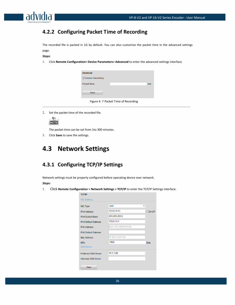
1. Click Remote Configuration > Network Settings > TCP/IP to enter the TCP/IP Settings interface:
VP-8-V2 and VP-16-V2 Series Encoder·User Manual
27
Figure 4. 8 TCP/IP Settings
2. Configure the NIC settings, including the NIC Type, IPv4 Address, IPv4 Subnet Mask, IPv4 Default Gateway,
and MTU settings.
The valid value range of MTU is 500 to 1500.
3. If the DHCP server is available, you can click the checkbox of DHCP to automatically obtain an IP address
and other network settings from that server.
4. If the DNS server settings are required for some applications (e.g., sending email), you should properly
configure the Preferred DNS Server and Alternate DNS Sever here.
Figure 4. 9 DNS Server Settings
5. Click the Save button to save the above settings.
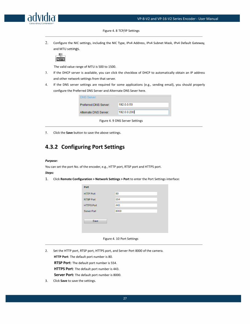
4.3.2 Configuring Port Settings
Purpose:
You can set the port No. of the encoder, e.g., HTTP port, RTSP port and HTTPS port.
Steps:
1. Click Remote Configuration > Network Settings > Port to enter the Port Settings interface:
Figure 4. 10 Port Settings
2. Set the HTTP port, RTSP port, HTTPS port, and Server Port 8000 of the camera.
HTTP Port: The default port number is 80.
RTSP Port: The default port number is 554.
HTTPS Port: The default port number is 443.
Server Port: The default port number is 8000.
3. Click Save to save the settings.
VP-8-V2 and VP-16-V2 Series Encoder·User Manual
28
It will ask you to reboot the device to activate the settings.
4.3.3 Configuring DDNS Settings
If your device is set to use PPPoE as its default network connection, you may set Dynamic DNS (DDNS) to be used
for network access.
Prior registration with your DDNS Provider is required before configuring the system to use DDNS.
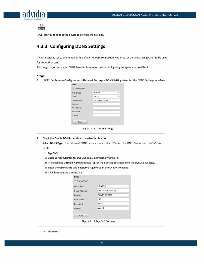
Steps: 1. Click the Remote Configuration > Network Settings > DDNS Settings to enter the DDNS Settings interface:
www.hiddns.com
Figure 4. 11 DDNS Settings
2. Check the Enable DDNS checkbox to enable this feature.
3. Select DDNS Type. Five different DDNS types are selectable: IPServer, DynDNS, PeanutHull, HiDDNS, and
NO-IP.
• DynDNS:
(1) Enter Server Address for DynDNS (e.g., members.dyndns.org).
(2) In the Device Domain Name text field, enter the domain obtained from the DynDNS website.
(3) Enter the User Name and Password registered in the DynDNS website.
(4) Click Save to save the settings.
Figure 4. 12 DynDNS Settings
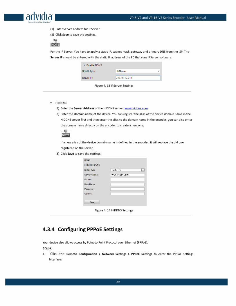
• IPServer:
VP-8-V2 and VP-16-V2 Series Encoder·User Manual
29
(1) Enter Server Address for IPServer.
(2) Click Save to save the settings.
For the IP Server, You have to apply a static IP, subnet mask, gateway and primary DNS from the ISP. The
Server IP should be entered with the static IP address of the PC that runs IPServer software.
Figure 4. 13 IPServer Settings
• HiDDNS:
(1) Enter the Server Address of the HiDDNS server: www.hiddns.com.
(2) Enter the Domain name of the device. You can register the alias of the device domain name in the
HiDDNS server first and then enter the alias to the domain name in the encoder; you can also enter
the domain name directly on the encoder to create a new one.
If a new alias of the device domain name is defined in the encoder, it will replace the old one
registered on the server.
(3) Click Save to save the settings.
Figure 4. 14 HiDDNS Settings
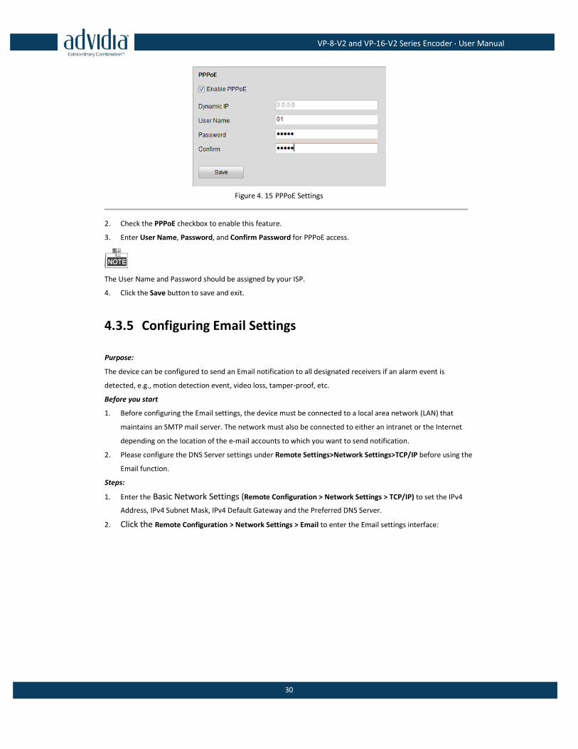
4.3.4 Configuring PPPoE Settings
Your device also allows access by Point-to-Point Protocol over Ethernet (PPPoE).
Steps:
1. Click the Remote Configuration > Network Settings > PPPoE Settings to enter the PPPoE settings
interface:
VP-8-V2 and VP-16-V2 Series Encoder·User Manual
30
Figure 4. 15 PPPoE Settings
2. Check the PPPoE checkbox to enable this feature.
3. Enter User Name, Password, and Confirm Password for PPPoE access.
The User Name and Password should be assigned by your ISP.
4. Click the Save button to save and exit.
4.3.5 Configuring Email Settings
Purpose:
The device can be configured to send an Email notification to all designated receivers if an alarm event is
detected, e.g., motion detection event, video loss, tamper-proof, etc.
Before you start
1. Before configuring the Email settings, the device must be connected to a local area network (LAN) that
maintains an SMTP mail server. The network must also be connected to either an intranet or the Internet
depending on the location of the e-mail accounts to which you want to send notification.
2. Please configure the DNS Server settings under Remote Settings>Network Settings>TCP/IP before using the
Email function.
Steps:
1. Enter the Basic Network Settings (Remote Configuration > Network Settings > TCP/IP) to set the IPv4
Address, IPv4 Subnet Mask, IPv4 Default Gateway and the Preferred DNS Server.
2. Click the Remote Configuration > Network Settings > Email to enter the Email settings interface:
VP-8-V2 and VP-16-V2 Series Encoder·User Manual
31
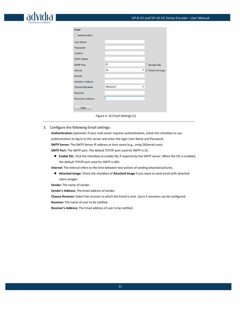
Figure 4. 16 Email Settings (1)
3. Configure the following Email settings:
Authentication (optional): If your mail server requires authentication, check this checkbox to use
authentication to log in to this server and enter the login User Name and Password.
SMTP Server: The SMTP Server IP address or host name (e.g., smtp.263xmail.com).
SMTP Port: The SMTP port. The default TCP/IP port used for SMTP is 25.
Enable SSL: Click the checkbox to enable SSL if required by the SMTP server. When the SSL is enabled,
the default TCP/IP port used for SMTP is 465.
Interval: The interval refers to the time between two actions of sending attached pictures.
Attached Image: Check the checkbox of Attached Image if you want to send email with attached
alarm images.
Sender: The name of sender.
Sender’s Address: The Email address of sender.
Choose Receiver: Select the receiver to which the Email is sent. Up to 3 receivers can be configured.
Receiver: The name of user to be notified.
Receiver’s Address: The Email address of user to be notified.
VP-8-V2 and VP-16-V2 Series Encoder·User Manual
32
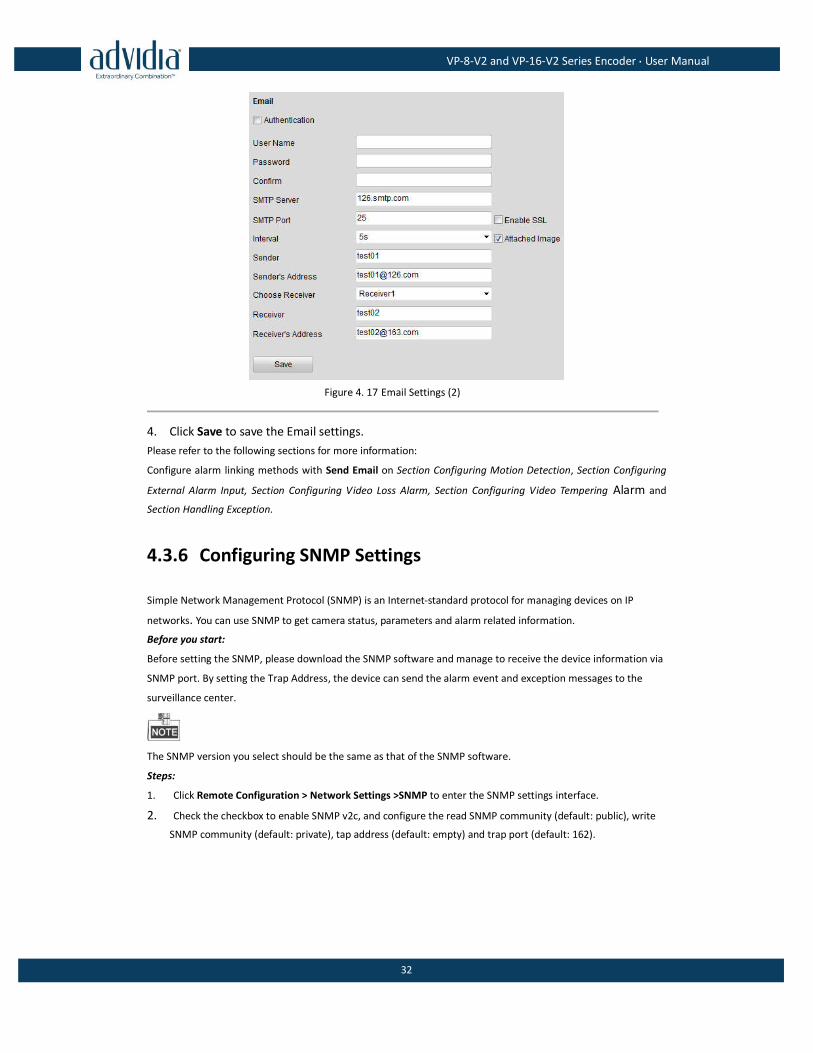
Figure 4. 17 Email Settings (2)
4. Click Save to save the Email settings.
Please refer to the following sections for more information:
Configure alarm linking methods with Send Email on Section Configuring Motion Detection, Section Configuring
External Alarm Input, Section Configuring Video Loss Alarm, Section Configuring Video Tempering Alarm and
Section Handling Exception.
4.3.6 Configuring SNMP Settings
Simple Network Management Protocol (SNMP) is an Internet-standard protocol for managing devices on IP
networks. You can use SNMP to get camera status, parameters and alarm related information.
Before you start:
Before setting the SNMP, please download the SNMP software and manage to receive the device information via
SNMP port. By setting the Trap Address, the device can send the alarm event and exception messages to the
surveillance center.
The SNMP version you select should be the same as that of the SNMP software.
Steps:
1. Click Remote Configuration > Network Settings >SNMP to enter the SNMP settings interface.
2. Check the checkbox to enable SNMP v2c, and configure the read SNMP community (default: public), write
SNMP community (default: private), tap address (default: empty) and trap port (default: 162).

VP-8-V2 and VP-16-V2 Series Encoder·User Manual
33
Figure 4. 18 SNMP Settings (1)
3. Set the SNMP port (default: 161).
4. Click Save to save the above settings.
4.3.7 Configuring UPnPTM Settings
Purpose:
UPnP™ can permit the device seamlessly discover the presence of other network devices on the network and
establish functional network services for data sharing, communications, etc. If you want to use the UPnP™
function to enable the fast connection of the device to the WAN via a router, you should configure the UPnP™
parameters of the device.
Before you start:
If you want to enable the UPnP™ function of the device, you must enable the UPnP™ function of the router to
which your device is connected. When the network working mode of the device is set as multi-address, the
Default Route of the device should be in the same network segment as that of the LAN IP address of the router.
Steps:
1. Click Remote Configuration > Network Settings > NAT to enter the NAT settings interface.
2. Check the checkbox to enable the UPnPTM function.
3. Select the Port Mapping Mode to Auto or Manual.
When you select Auto, the mapping ports can be automatically assigned by the router.
When you select Manual, you should continue Step4 to edit the mapping ports.
VP-8-V2 and VP-16-V2 Series Encoder·User Manual
34
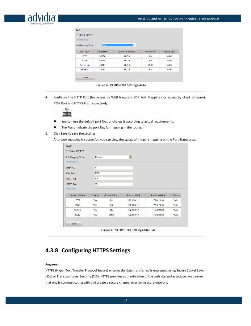
Figure 4. 19 UPnPTM Settings-Auto
4. Configure the HTTP Port (for access by WEB browser), SDK Port Mapping (for access by client software),
RTSP Port and HTTPS Port respectively.
You can use the default port No., or change it according to actual requirements.
The Ports indicate the port No. for mapping in the router.
5. Click Save to save the settings.
After port mapping is successful, you can view the status of the port mapping on the Port Status area.
Figure 4. 20 UPnPTM Settings-Manual
4.3.8 Configuring HTTPS Settings
Purpose:
HTTPS (Hyper Text Transfer Protocol Secure) ensures the data transferred is encrypted using Secure Socket Layer
(SSL) or Transport Layer Security (TLS). HTTPS provides authentication of the web site and associated web server
that one is communicating with and create a secure channel over an insecure network.
VP-8-V2 and VP-16-V2 Series Encoder·User Manual
35
HTTPS URLs begin with "https://" and use port 443 by default.
Steps:
1. Click Remote Configuration > Network Settings > HTTPS to enter the HTTPS settings interface.
2. Create the self-signed certificate or authorized certificate.
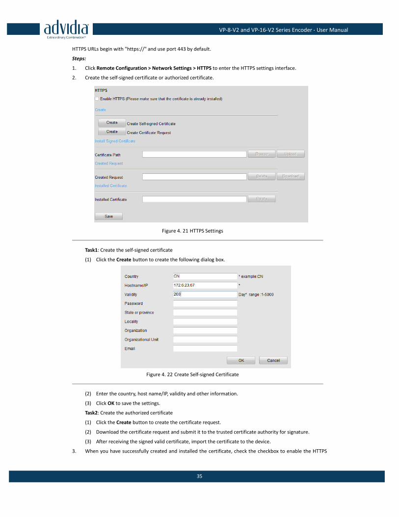
Figure 4. 21 HTTPS Settings
Task1: Create the self-signed certificate
(1) Click the Create button to create the following dialog box.
Figure 4. 22 Create Self-signed Certificate
(2) Enter the country, host name/IP, validity and other information.
(3) Click OK to save the settings.
Task2: Create the authorized certificate
(1) Click the Create button to create the certificate request.
(2) Download the certificate request and submit it to the trusted certificate authority for signature.
(3) After receiving the signed valid certificate, import the certificate to the device.
3. When you have successfully created and installed the certificate, check the checkbox to enable the HTTPS
VP-8-V2 and VP-16-V2 Series Encoder·User Manual
36
function.
After the HTTPS feature is enabled, the system will use the HTTPS login mode by default when you input the IP
address (e.g., https://192.0.0.64). You can also input http://IP address/index.asp (e.g., http://192.0.0.64/index.asp)
if you want to use HTTP mode to log into the device.
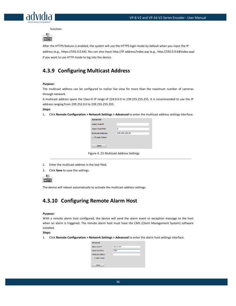
4.3.9 Configuring Multicast Address
Purpose:
The multicast address can be configured to realize live view for more than the maximum number of cameras
through network.
A multicast address spans the Class-D IP range of 224.0.0.0 to 239.255.255.255. It is recommended to use the IP
address ranging from 239.252.0.0 to 239.255.255.255.
Steps:
1. Click Remote Configuration > Network Settings > Advanced to enter the multicast address settings interface.
Figure 4. 23 Multicast Address Settings
2. Enter the multicast address in the text filed.
3. Click Save to save the settings.
The device will reboot automatically to activate the multicast address settings.
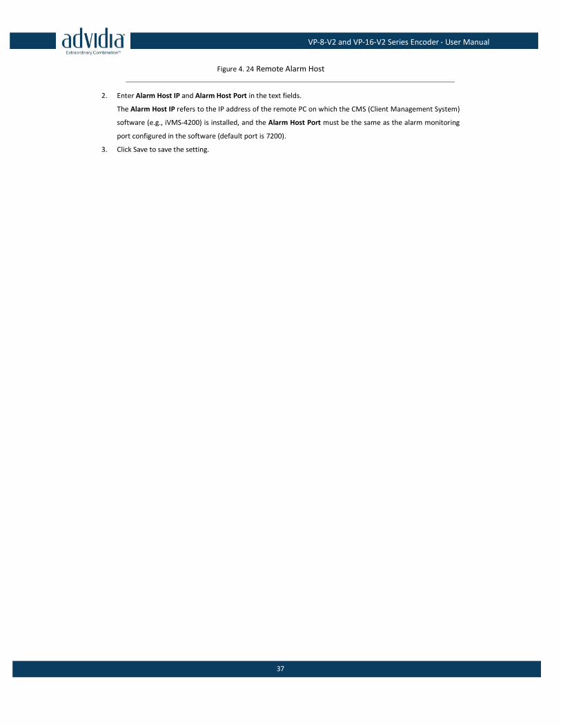
4.3.10 Configuring Remote Alarm Host
Purpose:
With a remote alarm host configured, the device will send the alarm event or exception message to the host
when an alarm is triggered. The remote alarm host must have the CMS (Client Management System) software
installed.
Steps:
1. Click Remote Configuration > Network Settings > Advanced to enter the alarm host settings interface.
VP-8-V2 and VP-16-V2 Series Encoder·User Manual
37
Figure 4. 24 Remote Alarm Host
2. Enter Alarm Host IP and Alarm Host Port in the text fields.
The Alarm Host IP refers to the IP address of the remote PC on which the CMS (Client Management System)
software (e.g., iVMS-4200) is installed, and the Alarm Host Port must be the same as the alarm monitoring
port configured in the software (default port is 7200).
3. Click Save to save the setting.
VP-8-V2 and VP-16-V2 Series Encoder·User Manual
38
Chapter 5 Camera Settings
5.1 Configuring OSD Settings
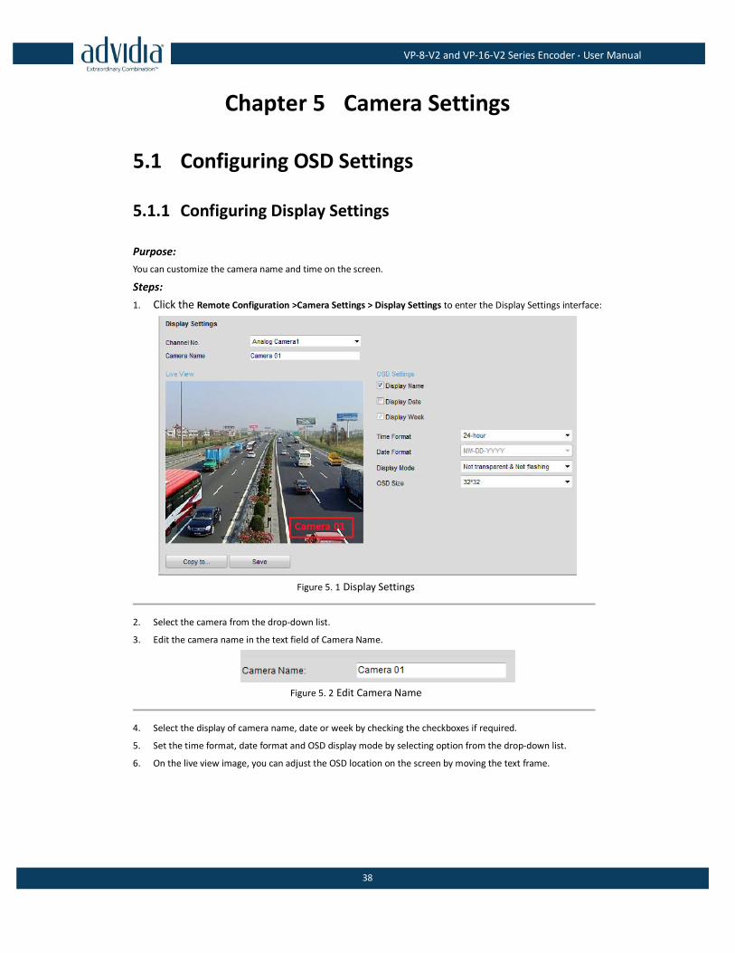
5.1.1 Configuring Display Settings
Purpose:
You can customize the camera name and time on the screen.
Steps:
1. Click the Remote Configuration >Camera Settings > Display Settings to enter the Display Settings interface:
Figure 5. 1 Display Settings
2. Select the camera from the drop-down list.
3. Edit the camera name in the text field of Camera Name.
Figure 5. 2 Edit Camera Name
4. Select the display of camera name, date or week by checking the checkboxes if required.
5. Set the time format, date format and OSD display mode by selecting option from the drop-down list.
6. On the live view image, you can adjust the OSD location on the screen by moving the text frame.
VP-8-V2 and VP-16-V2 Series Encoder·User Manual
39
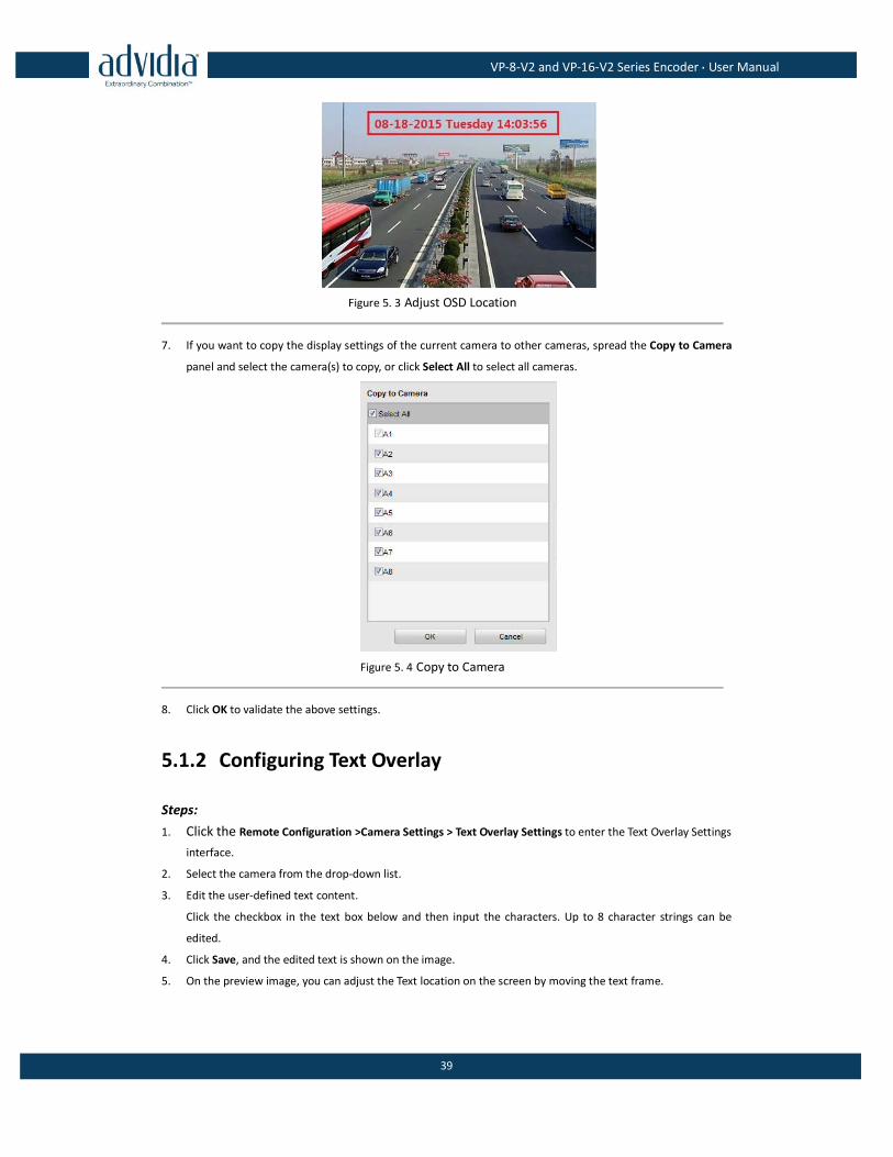
Figure 5. 3 Adjust OSD Location
7. If you want to copy the display settings of the current camera to other cameras, spread the Copy to Camera
panel and select the camera(s) to copy, or click Select All to select all cameras.
Figure 5. 4 Copy to Camera
8. Click OK to validate the above settings.
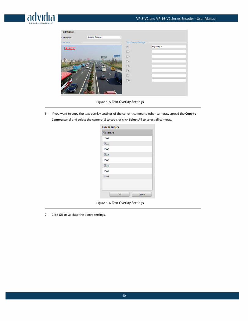
5.1.2 Configuring Text Overlay
Steps:
1. Click the Remote Configuration >Camera Settings > Text Overlay Settings to enter the Text Overlay Settings
interface.
2. Select the camera from the drop-down list.
3. Edit the user-defined text content.
Click the checkbox in the text box below and then input the characters. Up to 8 character strings can be
edited.
4. Click Save, and the edited text is shown on the image.
5. On the preview image, you can adjust the Text location on the screen by moving the text frame.
VP-8-V2 and VP-16-V2 Series Encoder·User Manual
40
Figure 5. 5 Text Overlay Settings
6. If you want to copy the text overlay settings of the current camera to other cameras, spread the Copy to
Camera panel and select the camera(s) to copy, or click Select All to select all cameras.
Figure 5. 6 Text Overlay Settings
7. Click OK to validate the above settings.
VP-8-V2 and VP-16-V2 Series Encoder·User Manual
41
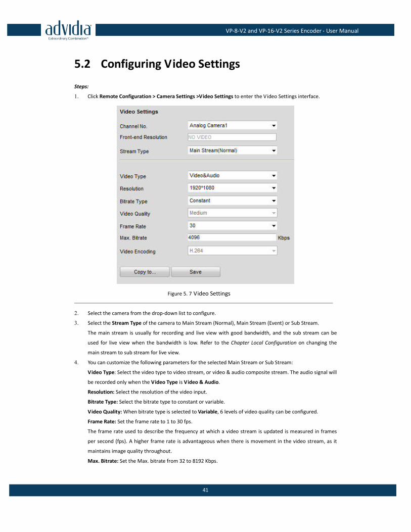
5.2 Configuring Video Settings
Steps:
1. Click Remote Configuration > Camera Settings >Video Settings to enter the Video Settings interface.
Figure 5. 7 Video Settings
2. Select the camera from the drop-down list to configure.
3. Select the Stream Type of the camera to Main Stream (Normal), Main Stream (Event) or Sub Stream.
The main stream is usually for recording and live view with good bandwidth, and the sub stream can be
used for live view when the bandwidth is low. Refer to the Chapter Local Configuration on changing the
main stream to sub stream for live view.
4. You can customize the following parameters for the selected Main Stream or Sub Stream:
Video Type: Select the video type to video stream, or video & audio composite stream. The audio signal will
be recorded only when the Video Type is Video & Audio.
Resolution: Select the resolution of the video input.
Bitrate Type: Select the bitrate type to constant or variable.
Video Quality: When bitrate type is selected to Variable, 6 levels of video quality can be configured.
Frame Rate: Set the frame rate to 1 to 30 fps.
The frame rate used to describe the frequency at which a video stream is updated is measured in frames
per second (fps). A higher frame rate is advantageous when there is movement in the video stream, as it
maintains image quality throughout.
Max. Bitrate: Set the Max. bitrate from 32 to 8192 Kbps.
VP-8-V2 and VP-16-V2 Series Encoder·User Manual
42
I Frame Interval: Set the I frame interval from 1 to 400 (frames). The higher value results in lower video
quality.
Video Encoding: Select the video encoding standard.
When the MJPEG video encoding standard is selected, the frame rate can be set to 1~15fps and the max.
bitrate is not configurable.
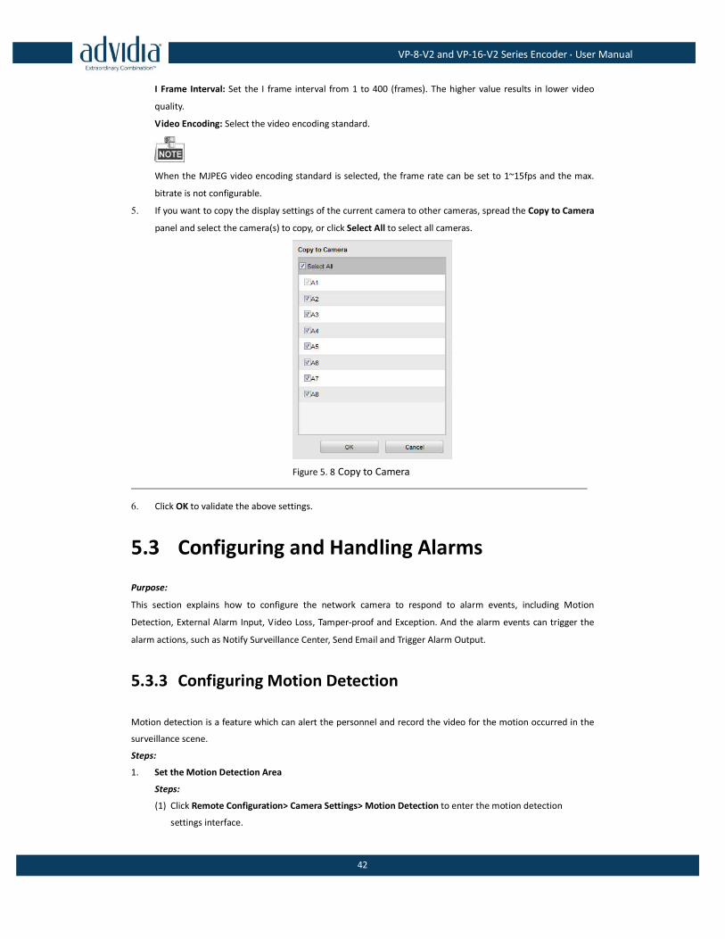
5. If you want to copy the display settings of the current camera to other cameras, spread the Copy to Camera
panel and select the camera(s) to copy, or click Select All to select all cameras.
Figure 5. 8 Copy to Camera
6. Click OK to validate the above settings.
5.3 Configuring and Handling Alarms
Purpose:
This section explains how to configure the network camera to respond to alarm events, including Motion
Detection, External Alarm Input, Video Loss, Tamper-proof and Exception. And the alarm events can trigger the
alarm actions, such as Notify Surveillance Center, Send Email and Trigger Alarm Output.
5.3.3 Configuring Motion Detection
Motion detection is a feature which can alert the personnel and record the video for the motion occurred in the
surveillance scene.
Steps:
1. Set the Motion Detection Area
Steps:
(1) Click Remote Configuration> Camera Settings> Motion Detection to enter the motion detection
settings interface.
VP-8-V2 and VP-16-V2 Series Encoder·User Manual
43
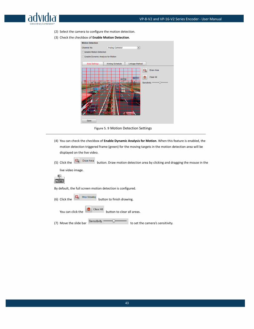
(2) Select the camera to configure the motion detection.
(3) Check the checkbox of Enable Motion Detection.
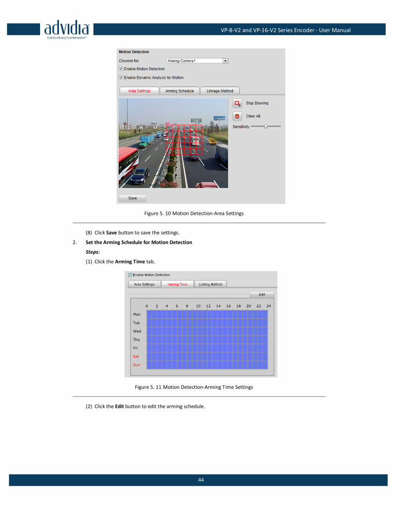
Figure 5. 9 Motion Detection Settings
(4) You can check the checkbox of Enable Dynamic Analysis for Motion. When this feature is enabled, the
motion detection triggered frame (green) for the moving targets in the motion detection area will be
displayed on the live video.
(5) Click the button. Draw motion detection area by clicking and dragging the mouse in the
live video image.
By default, the full screen motion detection is configured.
(6) Click the button to finish drawing.
You can click the button to clear all areas.
(7) Move the slide bar to set the camera’s sensitivity.
VP-8-V2 and VP-16-V2 Series Encoder·User Manual
44
Figure 5. 10 Motion Detection-Area Settings
(8) Click Save button to save the settings.
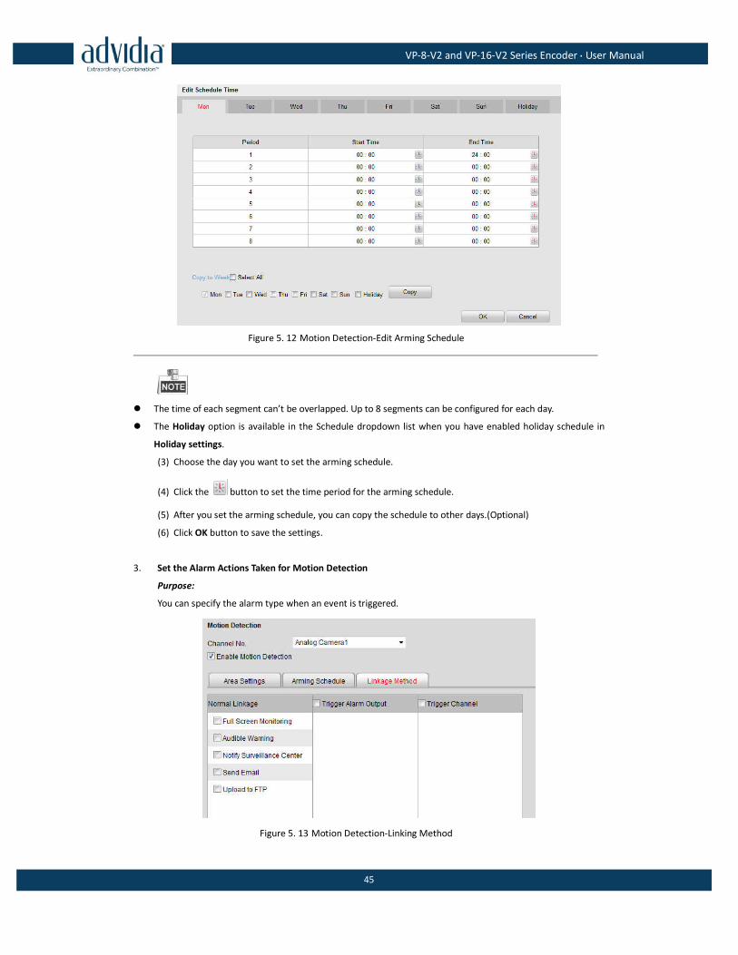
2. Set the Arming Schedule for Motion Detection
Steps:
(1) Click the Arming Time tab.
Figure 5. 11 Motion Detection-Arming Time Settings
(2) Click the Edit button to edit the arming schedule.
VP-8-V2 and VP-16-V2 Series Encoder·User Manual
45
Figure 5. 12 Motion Detection-Edit Arming Schedule
The time of each segment can’t be overlapped. Up to 8 segments can be configured for each day.
The Holiday option is available in the Schedule dropdown list when you have enabled holiday schedule in
Holiday settings.
(3) Choose the day you want to set the arming schedule.
(4) Click the button to set the time period for the arming schedule.
(5) After you set the arming schedule, you can copy the schedule to other days.(Optional)
(6) Click OK button to save the settings.
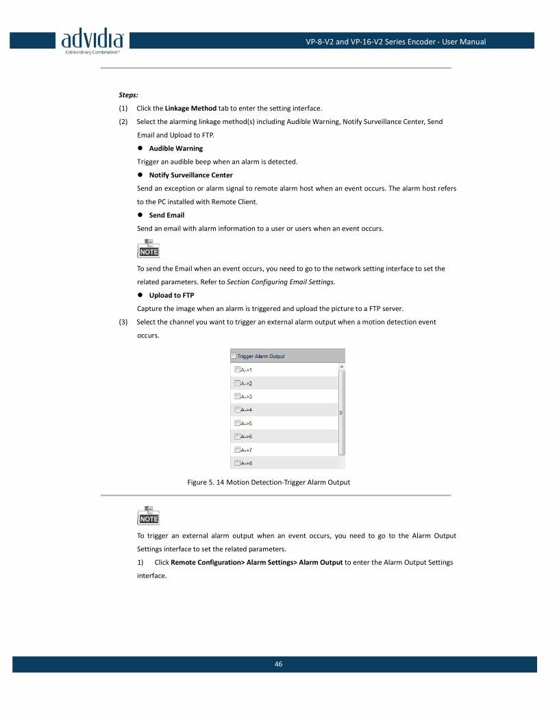
3. Set the Alarm Actions Taken for Motion Detection
Purpose:
You can specify the alarm type when an event is triggered.
Figure 5. 13 Motion Detection-Linking Method
VP-8-V2 and VP-16-V2 Series Encoder·User Manual
46
Steps:
(1) Click the Linkage Method tab to enter the setting interface.
(2) Select the alarming linkage method(s) including Audible Warning, Notify Surveillance Center, Send
Email and Upload to FTP.
Audible Warning
Trigger an audible beep when an alarm is detected.
Notify Surveillance Center
Send an exception or alarm signal to remote alarm host when an event occurs. The alarm host refers
to the PC installed with Remote Client.
Send Email
Send an email with alarm information to a user or users when an event occurs.
To send the Email when an event occurs, you need to go to the network setting interface to set the
related parameters. Refer to Section Configuring Email Settings.
Upload to FTP
Capture the image when an alarm is triggered and upload the picture to a FTP server.
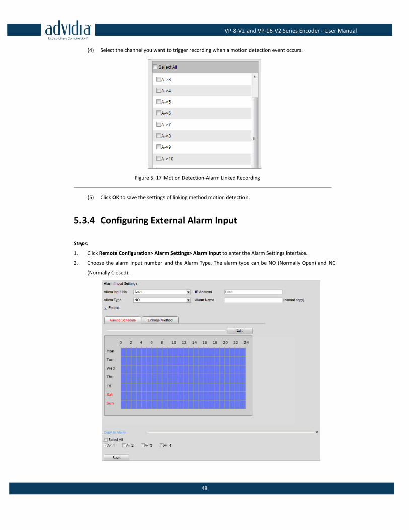
(3) Select the channel you want to trigger an external alarm output when a motion detection event
occurs.
Figure 5. 14 Motion Detection-Trigger Alarm Output
To trigger an external alarm output when an event occurs, you need to go to the Alarm Output
Settings interface to set the related parameters.
1) Click Remote Configuration> Alarm Settings> Alarm Output to enter the Alarm Output Settings
interface.
VP-8-V2 and VP-16-V2 Series Encoder·User Manual
47
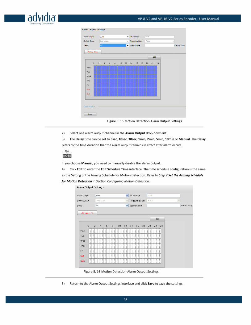
Figure 5. 15 Motion Detection-Alarm Output Settings
2) Select one alarm output channel in the Alarm Output drop-down list.
3) The Delay time can be set to 5sec, 10sec, 30sec, 1min, 2min, 5min, 10min or Manual. The Delay
refers to the time duration that the alarm output remains in effect after alarm occurs.
If you choose Manual, you need to manually disable the alarm output.
4) Click Edit to enter the Edit Schedule Time interface. The time schedule configuration is the same
as the Setting of the Arming Schedule for Motion Detection. Refer to Step 2 Set the Arming Schedule
for Motion Detection in Section Configuring Motion Detection.
Figure 5. 16 Motion Detection-Alarm Output Settings
5) Return to the Alarm Output Settings interface and click Save to save the settings.
VP-8-V2 and VP-16-V2 Series Encoder·User Manual
48
(4) Select the channel you want to trigger recording when a motion detection event occurs.
Figure 5. 17 Motion Detection-Alarm Linked Recording
(5) Click OK to save the settings of linking method motion detection.
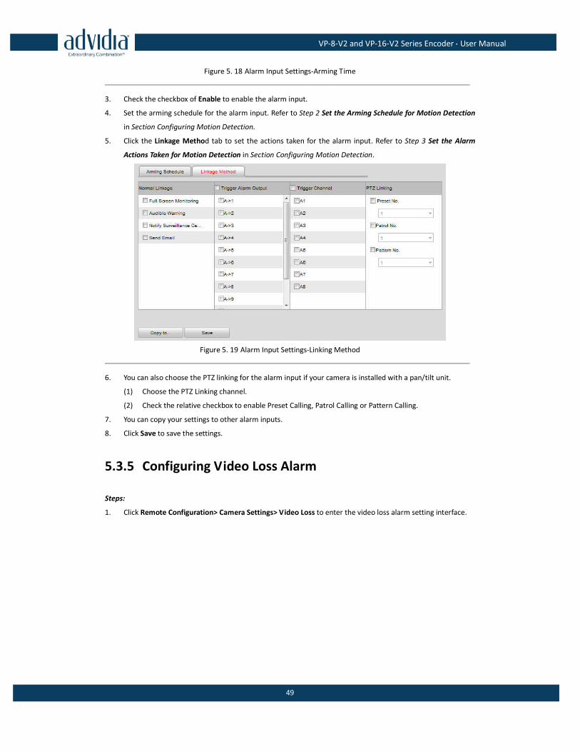
5.3.4 Configuring External Alarm Input
Steps:
1. Click Remote Configuration> Alarm Settings> Alarm Input to enter the Alarm Settings interface.
2. Choose the alarm input number and the Alarm Type. The alarm type can be NO (Normally Open) and NC
(Normally Closed).
VP-8-V2 and VP-16-V2 Series Encoder·User Manual
49
Figure 5. 18 Alarm Input Settings-Arming Time
3. Check the checkbox of Enable to enable the alarm input.
4. Set the arming schedule for the alarm input. Refer to Step 2 Set the Arming Schedule for Motion Detection
in Section Configuring Motion Detection.
5. Click the Linkage Method tab to set the actions taken for the alarm input. Refer to Step 3 Set the Alarm
Actions Taken for Motion Detection in Section Configuring Motion Detection.
Figure 5. 19 Alarm Input Settings-Linking Method
6. You can also choose the PTZ linking for the alarm input if your camera is installed with a pan/tilt unit.
(1) Choose the PTZ Linking channel.
(2) Check the relative checkbox to enable Preset Calling, Patrol Calling or Pattern Calling.
7. You can copy your settings to other alarm inputs.
8. Click Save to save the settings.
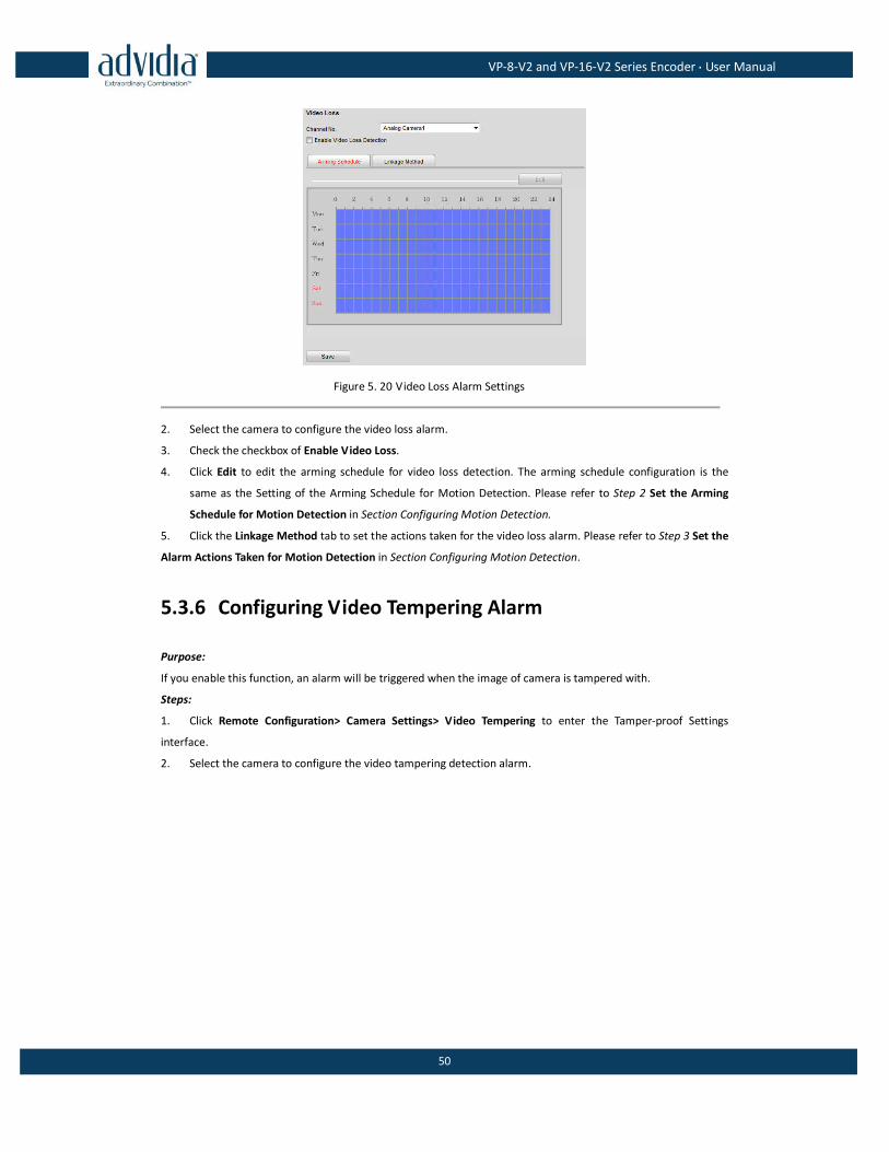
5.3.5 Configuring Video Loss Alarm
Steps:
1. Click Remote Configuration> Camera Settings> Video Loss to enter the video loss alarm setting interface.
VP-8-V2 and VP-16-V2 Series Encoder·User Manual
50
Figure 5. 20 Video Loss Alarm Settings
2. Select the camera to configure the video loss alarm.
3. Check the checkbox of Enable Video Loss.
4. Click Edit to edit the arming schedule for video loss detection. The arming schedule configuration is the
same as the Setting of the Arming Schedule for Motion Detection. Please refer to Step 2 Set the Arming
Schedule for Motion Detection in Section Configuring Motion Detection.
5. Click the Linkage Method tab to set the actions taken for the video loss alarm. Please refer to Step 3 Set the
Alarm Actions Taken for Motion Detection in Section Configuring Motion Detection.
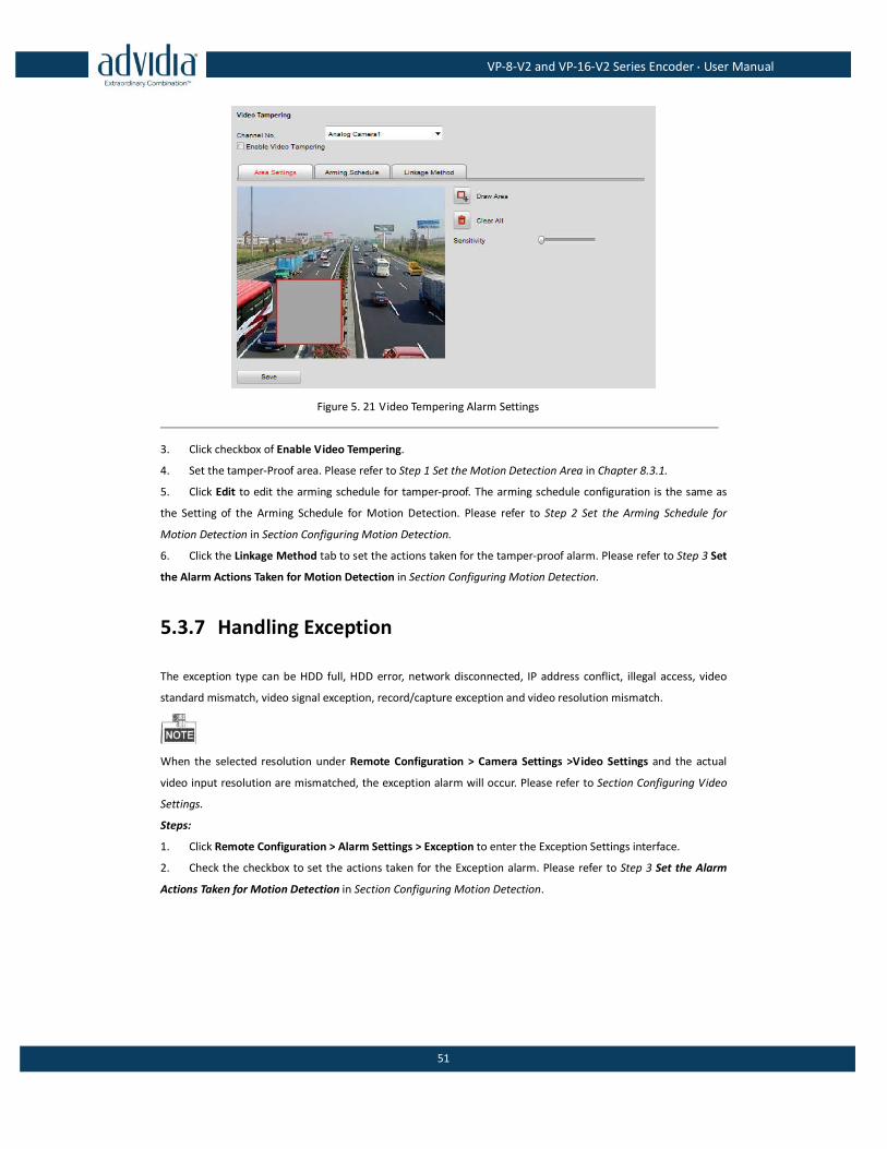
5.3.6 Configuring Video Tempering Alarm
Purpose:
If you enable this function, an alarm will be triggered when the image of camera is tampered with.
Steps:
1. Click Remote Configuration> Camera Settings> Video Tempering to enter the Tamper-proof Settings
interface.
2. Select the camera to configure the video tampering detection alarm.
VP-8-V2 and VP-16-V2 Series Encoder·User Manual
51
Figure 5. 21 Video Tempering Alarm Settings
3. Click checkbox of Enable Video Tempering.
4. Set the tamper-Proof area. Please refer to Step 1 Set the Motion Detection Area in Chapter 8.3.1.
5. Click Edit to edit the arming schedule for tamper-proof. The arming schedule configuration is the same as
the Setting of the Arming Schedule for Motion Detection. Please refer to Step 2 Set the Arming Schedule for
Motion Detection in Section Configuring Motion Detection.
6. Click the Linkage Method tab to set the actions taken for the tamper-proof alarm. Please refer to Step 3 Set
the Alarm Actions Taken for Motion Detection in Section Configuring Motion Detection.
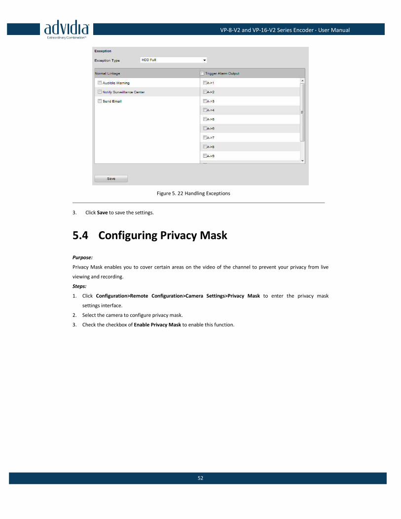
5.3.7 Handling Exception
The exception type can be HDD full, HDD error, network disconnected, IP address conflict, illegal access, video
standard mismatch, video signal exception, record/capture exception and video resolution mismatch.
When the selected resolution under Remote Configuration > Camera Settings >Video Settings and the actual
video input resolution are mismatched, the exception alarm will occur. Please refer to Section Configuring Video
Settings.
Steps:
1. Click Remote Configuration > Alarm Settings > Exception to enter the Exception Settings interface.
2. Check the checkbox to set the actions taken for the Exception alarm. Please refer to Step 3 Set the Alarm
Actions Taken for Motion Detection in Section Configuring Motion Detection.
VP-8-V2 and VP-16-V2 Series Encoder·User Manual
52
Figure 5. 22 Handling Exceptions
3. Click Save to save the settings.
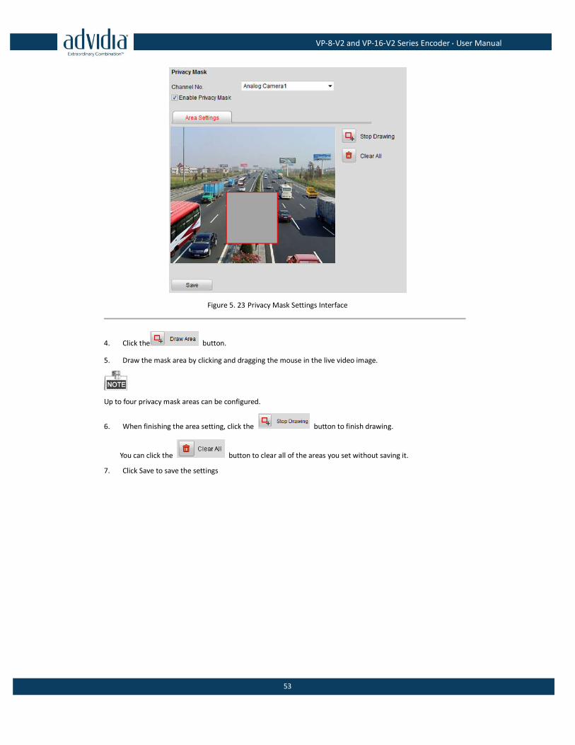
5.4 Configuring Privacy Mask
Purpose:
Privacy Mask enables you to cover certain areas on the video of the channel to prevent your privacy from live
viewing and recording.
Steps:
1. Click Configuration>Remote Configuration>Camera Settings>Privacy Mask to enter the privacy mask
settings interface.
2. Select the camera to configure privacy mask.
3. Check the checkbox of Enable Privacy Mask to enable this function.
VP-8-V2 and VP-16-V2 Series Encoder·User Manual
53
Figure 5. 23 Privacy Mask Settings Interface
4. Click the button.
5. Draw the mask area by clicking and dragging the mouse in the live video image.
Up to four privacy mask areas can be configured.
6. When finishing the area setting, click the button to finish drawing.
You can click the button to clear all of the areas you set without saving it.
7. Click Save to save the settings
VP-8-V2 and VP-16-V2 Series Encoder·User Manual
54
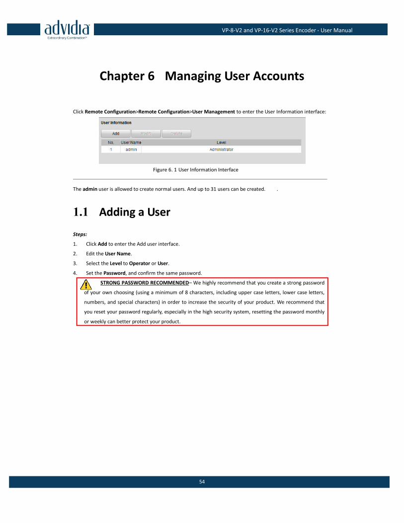
Chapter 6 Managing User Accounts
Click Remote Configuration>Remote Configuration>User Management to enter the User Information interface:
Figure 6. 1 User Information Interface
The admin user is allowed to create normal users. And up to 31 users can be created. .
1.1 Adding a User
Steps:
1. Click Add to enter the Add user interface.
2. Edit the User Name.
3. Select the Level to Operator or User.
4. Set the Password, and confirm the same password.
STRONG PASSWORD RECOMMENDED– We highly recommend that you create a strong password
of your own choosing (using a minimum of 8 characters, including upper case letters, lower case letters,
numbers, and special characters) in order to increase the security of your product. We recommend that
you reset your password regularly, especially in the high security system, resetting the password monthly
or weekly can better protect your product.
VP-8-V2 and VP-16-V2 Series Encoder·User Manual
55
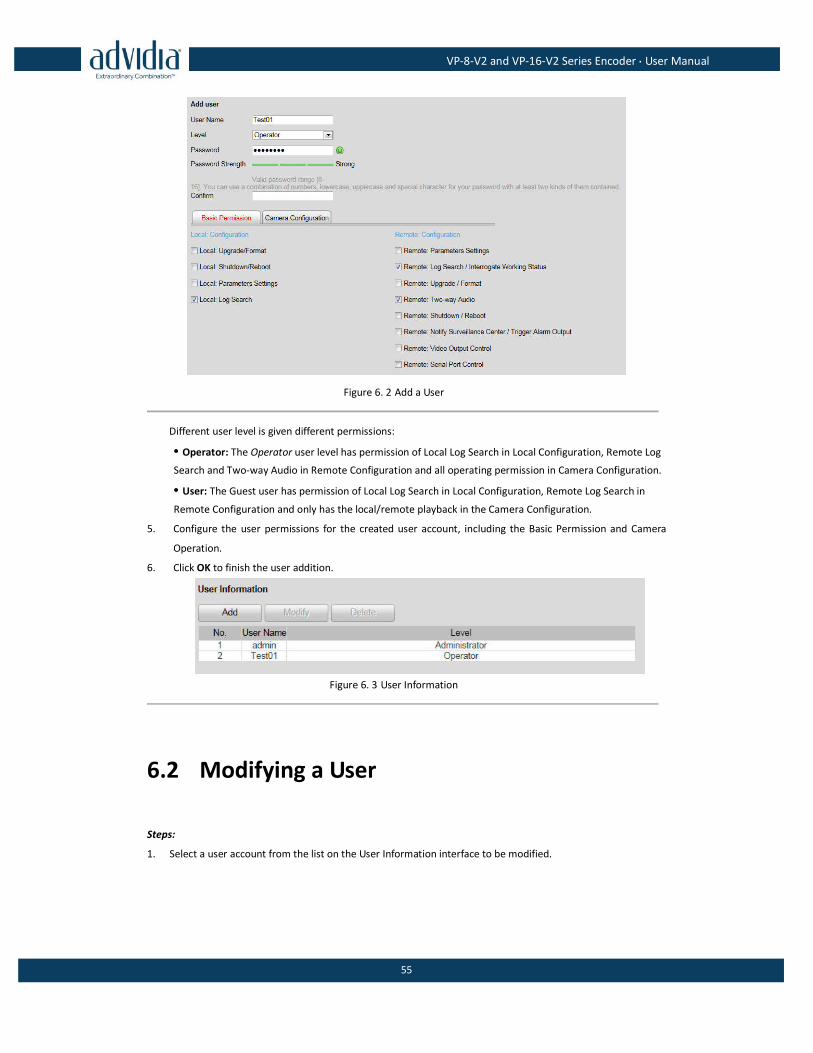
Figure 6. 2 Add a User
Different user level is given different permissions:
• Operator: The Operator user level has permission of Local Log Search in Local Configuration, Remote Log
Search and Two-way Audio in Remote Configuration and all operating permission in Camera Configuration.
• User: The Guest user has permission of Local Log Search in Local Configuration, Remote Log Search in
Remote Configuration and only has the local/remote playback in the Camera Configuration.
5. Configure the user permissions for the created user account, including the Basic Permission and Camera
Operation.
6. Click OK to finish the user addition.
Figure 6. 3 User Information
6.2 Modifying a User
Steps:
1. Select a user account from the list on the User Information interface to be modified.
VP-8-V2 and VP-16-V2 Series Encoder·User Manual
56
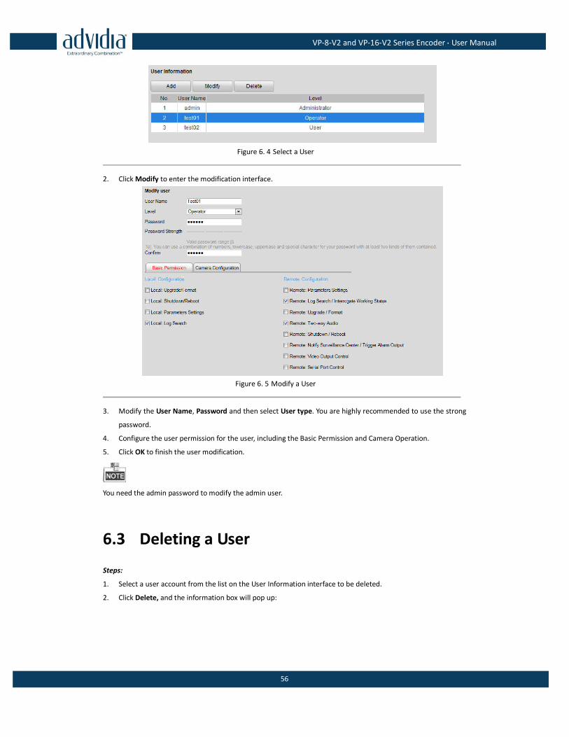
Figure 6. 4 Select a User
2. Click Modify to enter the modification interface.
Figure 6. 5 Modify a User
3. Modify the User Name, Password and then select User type. You are highly recommended to use the strong
password.
4. Configure the user permission for the user, including the Basic Permission and Camera Operation.
5. Click OK to finish the user modification.
You need the admin password to modify the admin user.
6.3 Deleting a User
Steps:
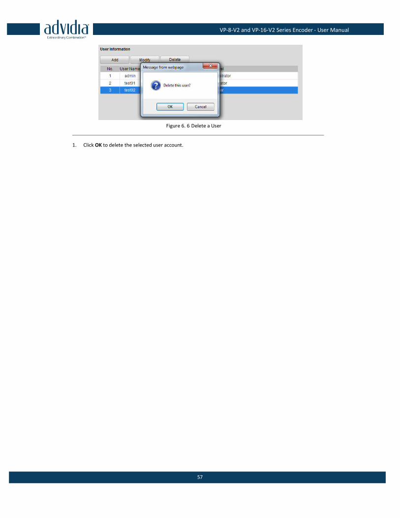
1. Select a user account from the list on the User Information interface to be deleted.
2. Click Delete, and the information box will pop up:
VP-8-V2 and VP-16-V2 Series Encoder·User Manual
57
Figure 6. 6 Delete a User
1. Click OK to delete the selected user account.
VP-8-V2 and VP-16-V2 Series Encoder·User Manual
58
Chapter 7 Maintenance
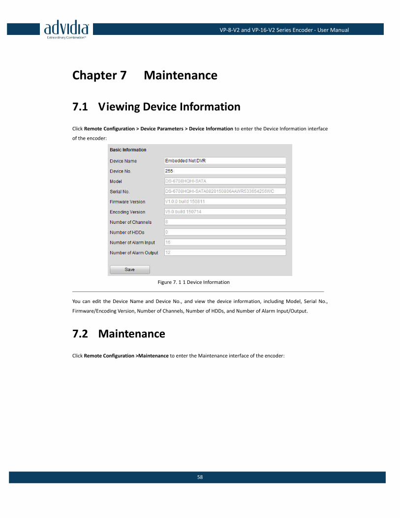
7.1 Viewing Device Information
Click Remote Configuration > Device Parameters > Device Information to enter the Device Information interface
of the encoder:
Figure 7. 1 1 Device Information
You can edit the Device Name and Device No., and view the device information, including Model, Serial No.,
Firmware/Encoding Version, Number of Channels, Number of HDDs, and Number of Alarm Input/Output.
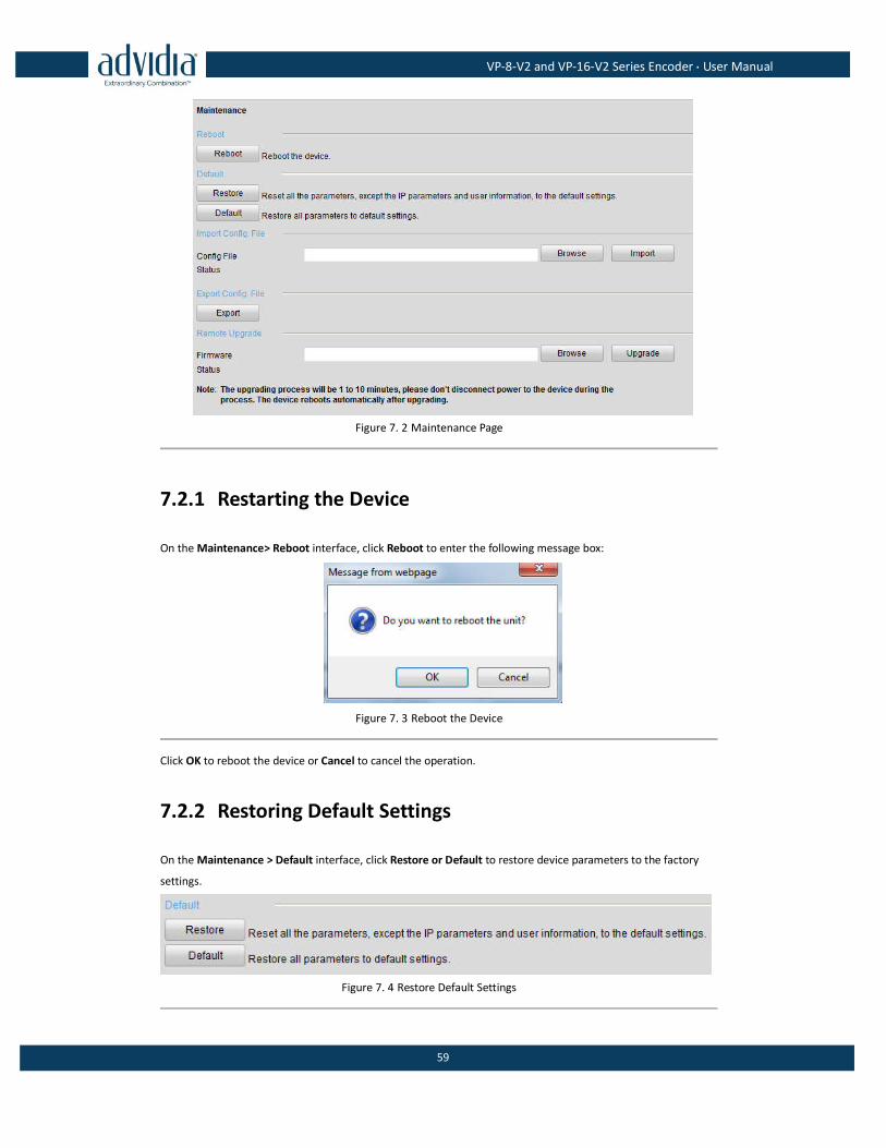
7.2 Maintenance
Click Remote Configuration >Maintenance to enter the Maintenance interface of the encoder:
VP-8-V2 and VP-16-V2 Series Encoder·User Manual
59
Figure 7. 2 Maintenance Page
7.2.1 Restarting the Device
On the Maintenance> Reboot interface, click Reboot to enter the following message box:
Figure 7. 3 Reboot the Device
Click OK to reboot the device or Cancel to cancel the operation.
7.2.2 Restoring Default Settings
On the Maintenance > Default interface, click Restore or Default to restore device parameters to the factory
settings.
Figure 7. 4 Restore Default Settings
VP-8-V2 and VP-16-V2 Series Encoder·User Manual
60
By selecting the Restore button, the device restores the default settings for the parameters except the IP
address, subnet mask, gateway and port.
By selecting the Default button, the device restores the default settings for all parameters.
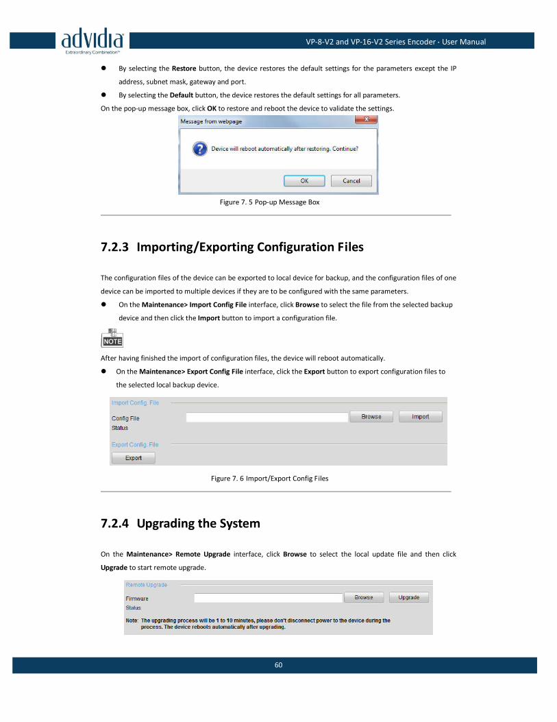
On the pop-up message box, click OK to restore and reboot the device to validate the settings.
Figure 7. 5 Pop-up Message Box
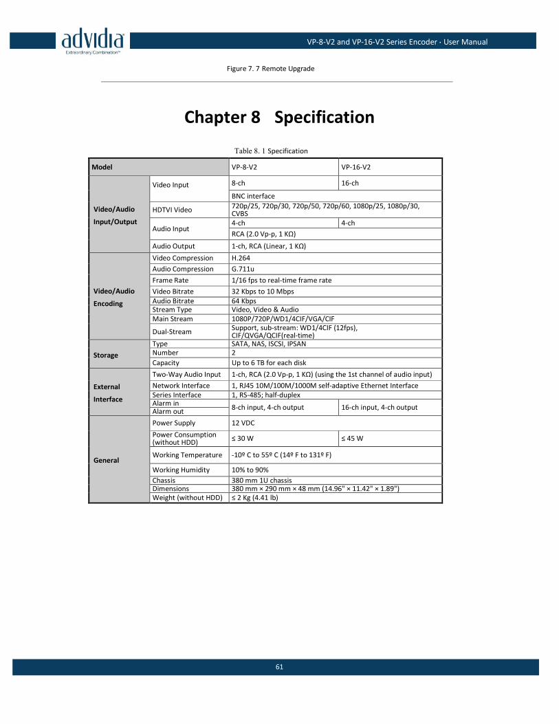
7.2.3 Importing/Exporting Configuration Files
The configuration files of the device can be exported to local device for backup, and the configuration files of one
device can be imported to multiple devices if they are to be configured with the same parameters.
On the Maintenance> Import Config File interface, click Browse to select the file from the selected backup
device and then click the Import button to import a configuration file.
After having finished the import of configuration files, the device will reboot automatically.
On the Maintenance> Export Config File interface, click the Export button to export configuration files to
the selected local backup device.
Figure 7. 6 Import/Export Config Files
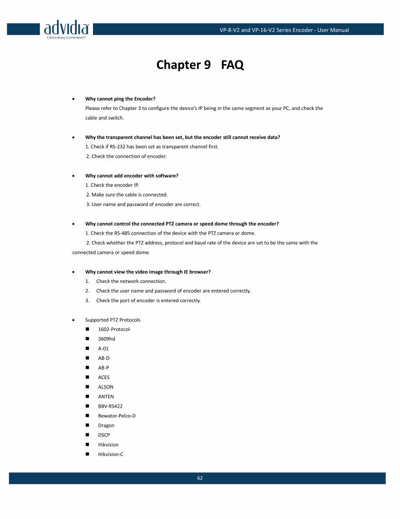
7.2.4 Upgrading the System
On the Maintenance> Remote Upgrade interface, click Browse to select the local update file and then click
Upgrade to start remote upgrade.
VP-8-V2 and VP-16-V2 Series Encoder·User Manual
61
Figure 7. 7 Remote Upgrade
Chapter 8 Specification
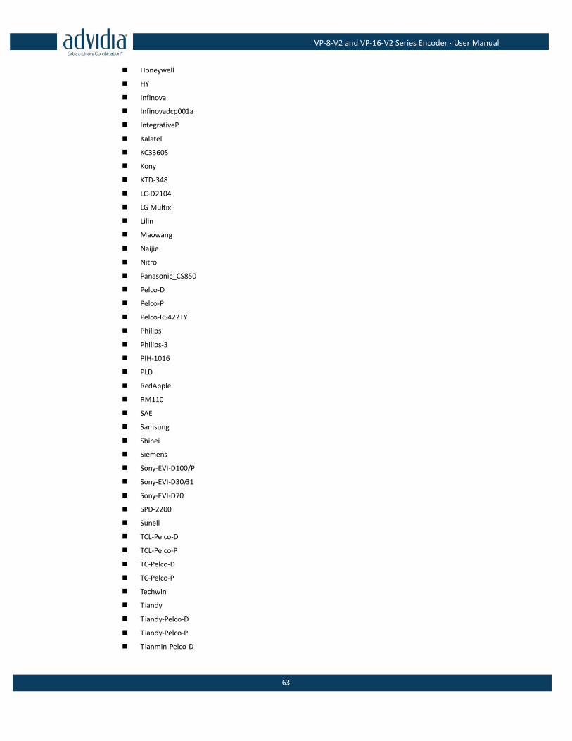
Table 8. 1 Specification
Model VP-8-V2 VP-16-V2
Video/Audio
Input/Output
Video Input
8-ch 16-ch
BNC interface
HDTVI Video 720p/25, 720p/30, 720p/50, 720p/60, 1080p/25, 1080p/30, CVBS
Audio Input 4-ch 4-ch
RCA (2.0 Vp-p, 1 KΩ)
Audio Output 1-ch, RCA (Linear, 1 KΩ)
Video/Audio
Encoding
Video Compression H.264
Audio Compression G.711u
Frame Rate 1/16 fps to real-time frame rate
Video Bitrate 32 Kbps to 10 Mbps Audio Bitrate 64 Kbps Stream Type Video, Video & Audio Main Stream 1080P/720P/WD1/4CIF/VGA/CIF
Dual-Stream Support, sub-stream: WD1/4CIF (12fps), CIF/QVGA/QCIF(real-time)
Storage
Type SATA, NAS, ISCSI, IPSAN Number 2
Capacity Up to 6 TB for each disk
External
Interface
Two-Way Audio Input 1-ch, RCA (2.0 Vp-p, 1 KΩ) (using the 1st channel of audio input)
Network Interface 1, RJ45 10M/100M/1000M self-adaptive Ethernet Interface Series Interface 1, RS-485; half-duplex Alarm in
8-ch input, 4-ch output 16-ch input, 4-ch output Alarm out
General
Power Supply 12 VDC
Power Consumption (without HDD)
≤ 30 W ≤ 45 W
Working Temperature -10º C to 55º C (14º F to 131º F)
Working Humidity 10% to 90%
Chassis 380 mm 1U chassis Dimensions 380 mm × 290 mm × 48 mm (14.96" × 11.42" × 1.89") Weight (without HDD) ≤ 2 Kg (4.41 lb)
VP-8-V2 and VP-16-V2 Series Encoder·User Manual
62
Chapter 9 FAQ
Why cannot ping the Encoder?
Please refer to Chapter 3 to configure the device’s IP being in the same segment as your PC, and check the
cable and switch.
Why the transparent channel has been set, but the encoder still cannot receive data?
1. Check if RS-232 has been set as transparent channel first.
2. Check the connection of encoder.
Why cannot add encoder with software?
1. Check the encoder IP.
2. Make sure the cable is connected.
3. User name and password of encoder are correct.
Why cannot control the connected PTZ camera or speed dome through the encoder?
1. Check the RS-485 connection of the device with the PTZ camera or dome.
2. Check whether the PTZ address, protocol and baud rate of the device are set to be the same with the
connected camera or speed dome.
Why cannot view the video image through IE browser?
1. Check the network connection.
2. Check the user name and password of encoder are entered correctly.
3. Check the port of encoder is entered correctly.
Supported PTZ Protocols
1602-Protocol
3609hd
A-01
AB-D
AB-P
ACES
ALSON
ANTEN
BBV-RS422
Bewator-Pelco-D
Dragon
DSCP
Hikvision
Hikvision-C
VP-8-V2 and VP-16-V2 Series Encoder·User Manual
63
Honeywell
HY
Infinova
Infinovadcp001a
IntegrativeP
Kalatel
KC3360S
Kony
KTD-348
LC-D2104
LG Multix
Lilin
Maowang
Naijie
Nitro
Panasonic_CS850
Pelco-D
Pelco-P
Pelco-RS422TY
Philips
Philips-3
PIH-1016
PLD
RedApple
RM110
SAE
Samsung
Shinei
Siemens
Sony-EVI-D100/P
Sony-EVI-D30/31
Sony-EVI-D70
SPD-2200
Sunell
TCL-Pelco-D
TCL-Pelco-P
TC-Pelco-D
TC-Pelco-P
Techwin
Tiandy
Tiandy-Pelco-D
Tiandy-Pelco-P
Tianmin-Pelco-D
VP-8-V2 and VP-16-V2 Series Encoder·User Manual
64
Tianmin-Pelco-P
TL-HHX2000
TL-Pelco-P
TL-V1200
VC-2000PTC-C
VCL
Vicon
VIDO B-01
VIDO B-02
YAAN-1
YAAN-2
YF-06
YOULI