Embed Size (px)
Citation preview

Servo Drive Solutions
0.5 hp - 100 hp Heavy Duty (0.37 kW - 75 kW)230 V | 460 V
Unidrive SP:Servo

2 www.emersonindustrial.com/automation
Unidrive SP – Advanced Solutions Platform for Servo Motor Control
N1652E171230
ENVIROMENTALMANAGEMENT
Certificate No. EMS 54446 003
ISO 14001
QUALITYMANAGEMENT
Certificate No. Q 05176 003
ISO 9001
Control Techniques’ Unidrive SP delivers dynamic performance to operate a wide array of servo motor types and power ratings. Snap-in SM option modules allow the addition of programming platforms, distributed or centralized control architecture, I/O, communications and feedback to tailor the solution to specific application needs.
Modbus communications port for PC programming and device interfacing
Optional keypad, available as high- brightness LED or multi-language LCD with plain text
SmartCard for parameter, PLC program storage
Terminal cover for DC bus, low voltage power supply and on board EMC filter
Plug-in connections with removable terminals*
3 universal SM option module slots for communications, I/O, additional feedback devices and automation/motion controllers*
Internal EMC filter with easy disconnect
Universal encoder port supporting Incremental, SinCos, SSI, EnDAT and HIPERFACE encoder types
Drive identification marker rail
Aluminium heatsink: drive can be mounted on a flat surface, or through panel mounted so that the heat is dissipated outside the enclosure*
Power On / Drive Status LED
* Features and their locations vary on some drive sizes
Power connections with removable terminals*
Relay connections

3www.emersonindustrial.com/automation
One Drive, Any Power, Any MotorThe Unidrive SP is a universal AC and Servo drive with ratings from 0.5 to 2,900hp. This field-proven drive features dynamic servo performance with a wide array of power, motor types and snap-in SM option modules including programming/automation platforms, distributed or centralized control, I/O, communications and feedback to tailor the solution to your exact needs. (For full details on the wide range of available option modules, please see the Control Techniques SM Option Modules brochure.)
Panel Mount – Standard Drives0.5 hp to 100 hp (0.37 kW to 75 kW)
Unidrive SP Panel Mount drives are standard AC input, AC output sizes for installation within a control panel. Optional conduit boxes are available for wall mounting.
Ratings
Performance Advantage
Servo Motor ControlClosed-loop servo motor control and power regeneration control features in one drive
Induction Motor ControlClosed-loop motor control for motion control applications
24Vdc Auxiliary Power Supply InputMaintains control, network communications and position loop on input AC power loss, minimizing system recovery time
Comprehensive Auto-TuneInertia monitoring and static auto-tune reduce startup time
Universal Feedback InterfaceSupports 14 different types of feedback devices, including several absolute encoders; multiple encoders can be connected to a single drive with SM option modules
High-Resolution Analog Input16-bit, 250µsec interface for high-performance applications; two additional 10-bit analog inputs for lower level controls
Extensive Fieldbus ConnectivityModbusRTU (Standard), Profibus-DP, EtherNet/IP, Modbus TCP/IP, DeviceNet, CAN, CANOpen, EtherCAT, SERCOS, Interbus-S and CTNet/CTSync optional via zero-space option modules; up to four fieldbus devices can connect to a single drive, eliminating the need for expensive gateways
Universal SM Option Module SlotsUnidrive SP size 0 has two slots; Unidrive SP sizes 1 and up have three option module slots; SM-Fieldbus, I/O and Application modules fit in any of the open module slots
Safe Torque Off FunctionConforms to IEC61800-5-1, SIL 3 and EN954-1 Category 3 for machine safety and system cost reduction
SmartCard for Simple Set-up and CloningEasy-to-use card stores drive configuration for simple startup and parameter cloning — supplied free with every Unidrive SP
Keypad OptionsChoose no keypad, LED keypad or LCD keypad based on the system design and operating environment
Drive-Mounted Brake ResistorsUnidrive SP sizes 0, 1 and 2 feature a drive-mounted brake resistor option to reduce panel space requirements
0.5 3 25 50 75
Heavy Duty
Horsepower Range
200-240V, 1Ø
200-240V, 3Ø
380-480V, 3Ø
2 100
Input Voltage
10

4 www.emersonindustrial.com/automation
Featured SM Option ModulesTo provide the best possible dynamic motor performance, the following Control Techniques SM option modules contain a high-performance microprocessor that allows the base drive to be dedicated to motion control as well as machine control.
SM-EZMotionThe SM-EZMotion option module and Control Techniques’ FREE PowerTools Pro software provide a user-friendly environment for easy “out-of-the-box” configuration and motion
programming. The EZMotion approach is ideal for rapid development of motion application solutions. The module has four digital inputs and two digital outputs for high-speed I/O operations.
SM-Applications PlusSM-Applications Plus offers all of the features of the SM-Applications Lite V2 module plus Control Techniques’ CTNet network interface (see below), RS485 serial port and high-speed I/O. The
SM-Applications Plus option module is programmed using SyPTPro (System Programming Tool).
• Drive-to-drive communications: SM-Applications Plus option modules include a high-speed, drive-to-drive network called CTNet. This network is optimized for intelligent drive systems offering flexible peer-to-peer communications. CTNet has the capability to connect to remote I/O, operator panels, Mentor MP DC drives and PCs providing the ability to perform true parallel multi-tasking.
•Control Techniques’ CTSync is also standard on the SM-Applications Plus module, providing drive-to-drive synchronization with <4µsec jitter.
•Inputs/Outputs: This module has two digital inputs and two digital outputs for high-speed I/O operations such as position capture and actuator firing.
Automation Solutions
Unidrive SP programmable drives provide compact, higher-performance and lower-cost solutions in machinery automation applications. Over the past 30 years, Control Techniques has pioneered the embedding of programmable automation, motion control and communications features within its drive products.
SM-Applications Lite V2The SM-Applications Lite V2 option module provides programmable control for standalone drive applications or when the drive is connected to a centralized controller via I/O or fieldbus. SM-
Applications Lite V2 may be programmed using Ladder Logic with SyPTLite or can use the full automation and motion control capabilities contained within SyPTPro, IEC 61131-3 software (see page 8 for more information).
• Real-time control: The SM-Applications Lite V2 module provides real-time access to all of the drive’s parameters plus access to data from I/O and other drives. The module uses a high-speed multi-tasking operating system with task update times as low as 250µs. Tasks are synchronized to the drive’s own control loops to give you the best possible performance for drive control and motion.
SM-RegisterThe SM-Register option module is designed to provide a flexible, high-performance solution for programmable motion requiring high-speed registration features – ideal for applications such
as printing, packaging and cutting machinery.
Features include:
•Motion programming using PLCopen or Control Techniques’ Advanced Position Controller (APC)
•Two fully independent registrations capture channels•Storage for 256 events per channel, microseconds apart•Pattern recognition•Speed capacity in excess of 3000ft/min•Ability to filter unwanted marks (i.e. splashes, dirt, text, etc.)
• Minimum and/or maximum pulse width
• Distance from previous edge
•Compensation for registration sensor throughput delay•CTNet and CTSync functionality
5www.emersonindustrial.com/automation
Unidrive SP “Base.” With up to 14 different motor feedback options, the base Unidrive SP can be easily controlled with single- and multi-axis controllers, PLC’s and host controllers for medium- to high-power applications. The analog torque or velocity modes can be used with classic position controllers using analog outputs and encoder inputs. The drive can be controlled over a SERCOS or EtherCAT network with the addition of an SM-SERCOS or SM-EtherCAT option module.
Drive set-up parameters can be easily stored on a credit card -sized SmartCard. Simple sequencing logic can be accomplished using the onboard Ladder editor. Configuration and diagnostics is performed using the FREE CTSoft software tool.
Unidrive SP “EZ” (Base drive + SM-EZMotion module). With out-of-the-box motion control in minutes, the Unidrive SP is the ultimate servo drive in terms of ease of use and motion performance. Utilizing a familiar Windows® interface, machine builders can use PowerTools Pro software to quickly set up and program the Unidrive SP “EZ” to perform almost any motion profile. Applications requiring camming, indexing, electronic gearing, velocity and torque modes can be accomplished through simple drag-and-drop, fill-in-the-blank set-up. Real-time programs with “Basic-like” command structured text can be used to program the machine sequencing. The programming interface guides the user through the drive, I/O and motion configurations. The drive offers a standalone solution for many common indexing and synchronized motion applications.
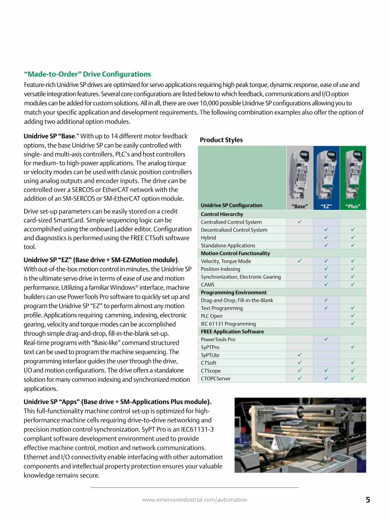
Unidrive SP “Apps” (Base drive + SM-Applications Plus module). This full-functionality machine control set-up is optimized for high-performance machine cells requiring drive-to-drive networking and precision motion control synchronization. SyPT Pro is an IEC61131-3 compliant software development environment used to provide effective machine control, motion and network communications. Ethernet and I/O connectivity enable interfacing with other automation components and intellectual property protection ensures your valuable knowledge remains secure.
“Made-to-Order” Drive ConfigurationsFeature-rich Unidrive SP drives are optimized for servo applications requiring high peak torque, dynamic response, ease of use and versatile integration features. Several core configurations are listed below to which feedback, communications and I/O option modules can be added for custom solutions. All in all, there are over 10,000 possible Unidrive SP configurations allowing you to match your specific application and development requirements. The following combination examples also offer the option of adding two additional option modules.
Unidrive SP Configuration “Base” “EZ” “Plus”
Control Hierarchy
Centralized Control System üDecentralized Control System ü üHybrid ü üStandalone Applications ü üMotion Control Functionality
Velocity, Torque Mode ü ü üPosition-Indexing ü üSynchronization, Electronic Gearing ü üCAMS ü üProgramming Environment
Drag-and-Drop, Fill-in-the-Blank üText Programming ü üPLC Open üIEC 61131 Programming üFREE Application Software
PowerTools Pro üSyPTPro üSyPTLite üCTSoft ü üCTScope ü ü üCTOPCServer ü ü ü
Product Styles

6 www.emersonindustrial.com/automation
“Motion Made Easy™ ”
Each step is configured using simple check boxes, drop-down selections and drag-and-drop functionality. A straightforward programming language allows users to develop more complex applications and advanced sequencing by simply dragging functions onto the work area and dropping them in place.
Motion Made Easy™ Solutions
PowerTools Pro Software for Unidrive SP EZMotionPowerTools Pro software provides advanced motion control programming for Control Techniques drives with internal motion controller. This FREE software enables users to fully realize the power of our EZMotion motion controller. A familiar Microsoft® Windows® interface provides operators and machine builders with the tools needed to access everything they need for complete servo control — PLS, Queueing, High-Speed Capture, Electronic Gearing, Event Assignments and more.
Developing motion applications with PowerTools Pro is a simple “five-step, top-down” process. The five steps are displayed in a familiar “explorer” bar (insert, left) for easier navigation:
• Hardware configuration
• Drive setup• I/O setup
• Motion• Programs
Assignments – Use “virtual wiring” to create programs right out of the box without writing a single line of code. For example, the assignment screen (below) allows you to drag-and-drop the desired machine function onto the digital inputs and outputs.
Indexes – Indexes are easily set up by filling in the screen’s blanks to create an index profile. Select from Incremental, Absolute, Registration or Rotary Plus and Minus types. “Position Tracker™” synchronization is easily achieved using menu selections. Choose the time base of the index by selecting either real-time or synchronization with a master.
Microsoft and Windows are registered trademarks of Microsoft Corporation in the United States and other countries.

7www.emersonindustrial.com/automation
Software Matched to Your Application Requirements
Camming – Cams make set-up and programming of complex motion profiles easy. The use of real-time programs provides smooth transitions when switching between cam profiles on the fly. Cam data is easily imported within PowerTools Pro and the cam graphing tool features multiple interpolation types.
Network – Regardless of the fieldbus being used, setting up network com-munications is quick and easy. Fill-in-the-blank, drag-and-drop procedures are used to set up communication. PowerTools Pro’s diagnostics allow you to monitor the data being sent and received.
PowerTools Pro continued
Sophisticated motion routines such as camming, gearing or multiple profile summation are easily implemented with PowerTools Pro and Unidrive SP.
Typical Applications
www.controltechniques.com
Sensor
Master AxisEncoder
NT Motor
CTVueOperatorInterface
AC Motor
Unidrive M200
Unidrive SP
Unid
Random Infeed – Smartbelt High-Speed Labeling

8 www.emersonindustrial.com/automation
Ladder Logic
SyPTPro is the ideal format for sequencing and I/O control familiar to all PLC programmers. Using an SM-Applications Plus module, over 5,000 rungs of logic may be stored and executed. All normal Ladder Logic functions are available plus high-level blocks for communications, word manipulation, math operands and much more.
Drive Programming Language (DPL)DPL is a structured text language as easy to use as BASIC, incorporating many standard constructs such as IF-THEN-ELSE and FOR-NEXT loops. DPL is ideal for initializing, configuration and general programming of Control Techniques drives. DPL may be mixed throughout the program with the other graphical editors such as Ladder Logic.
PLCopen (Open Motion Programming)PLCopen-style programming for motion control uses industry-standard Function Blocks for motion control resulting in reduced development time.
SyPTPro (Systems Programming Toolkit)
SyPTPro is a full-featured automation development environment that can be used for developing tailored solutions for single- or multiple-drive applications. The programming environment fully supports three IEC 61131 languages: Function Block, Ladder Logic and Structured Text. Motion control is configured using PLCopen motion language, supporting multiple axes.
CTNet, a high-speed, deterministic drive-to-drive network links the drives, SCADA and I/O together to form a networked system, with SyPTPro managing both the application programs and network communications.
Programming FlexibilitySyPTPro can be used with three programming languages — Function Block diagram, Ladder Logic and Drive Programming Language (DPL). The software offers a multi-tasking environment in which tasks are scheduled according to the required speed of execution or triggered by events.
Function Block
SyPTPro includes a library of more than 380 Function Blocks for both simple and complex functions. In addition to the defined Function Blocks, users can create User Defined Function Blocks (UDFB). This feature allows users to create special functions. It is also possible to use pre-defined Function Blocks inside the UDFB. Intellectual property can be protected by creating a UDFB that allows access only to authorized source code users.
Flexible Automation Software

9www.emersonindustrial.com/automation
Additional Software
CTOPC ServerOPC is the industry standard for connecting industrial automation components to higher-level information systems such as SCADA, MRP, ERP and others. Control Techniques’ CTOPC server is an OPC-compliant server that allows PCs to communicate with Control Techniques drives via Ethernet, CTNet, RS485 and USB. The OPC standard allows OPC clients to browse data from an OPC server thus eliminating the need for gateway data concentrators or proprietary drivers and gateways. CTOPC server “serves” data to the various OPC clients then polls data from all Control Techniques components connected via Modbus RTU, Modbus TCP/IP or CTNet.
SERVOSoft
SERVOsoft CTA is a standalone software tool designed to help you select the optimum servo drive and motor combination for your machine in 8 easy steps using the EasySize Wizard tool:
1. Select the number of axes and electrical configuration2. Name the axes to match your machine3. Select the load type for each axis4. Define the motion profile for each axis5. Enter the mechanical characteristics6. Add any mechanical transmission elements7. Select drives and motors products from the database8. Run a system check to ensure the products selected meet
all of the desired operating conditions
CTScope
This Windows®-based software utility is designed to trend/trace parameter values on Control Techniques drives and option modules. CTScope has the look and feel of a traditional hardware oscilloscope and can plot up to four channels of data simultaneously. All channel data appears in single-scope view for easy comparison and CTScope files can be saved for future use.
CTSoft
Control Techniques’ free drive configuration tool can be used to commission, optimize and monitor Unidrive SP “Base” drives. CTSoft uses wizards to simplify commissioning, manages data stored on the SmartCard and features robust and graphical tools for monitoring and troubleshooting. The status of the program can be monitored and the speed of the motion reduced for commissioning and testing purposes.

10 www.emersonindustrial.com/automation
Unidrive SP, fast and easy integration flexibility
Input / Output
Standard
Communications
Modbus RTU
Standard Options
SM Option Modules
EtherNet/IP, Modbus TCP/IP, email, web server, simple network time Protocol
SM-ETHERNET:SM-CAN SM-CANOPEN SM-DEVICENET SM-ETHERCAT
SM-INTERBUSSM-PROFIBUS-DPSM-PROFINETSM-SERCOS
Applications with PLC or Motion Functionality
5 Analog input/outputs7 Digital input/outputs 1 Safe Torque Off
TCP/IP
RTU
Options
SM-I/O-32 (32 digital I/O) SM-I/O-24V (protected) SM-I/O-LITE SM-I/O-PELVSM-I/O-TIMER (Real-Time Clock) SM-I/O-120V (120Vac I/O) SM-I/O-PLUS
SM Option Modules Remote I/O
24V 0V
PE PEBECKH
OFF
CTNet
HEALTHY
BUS ERR
COM RUN
INIT ERR
I/O RUN
I/O ERR
BK
72
00
1
2
3
4
5
6
7
8
See the Options & Accessories brochure for order codes
Operator Interface Options
SmartCard
Memory device to
store and copy drive parameters
SMARTCARD
HMI Operator Interface
See the Options & Accessories brochure for order codes
LCD Keypad
Interconnect Cable See Options & Accessories brochure for order codes
LED Keypad
Drive mount LED display to IP65
(NEMA 12)Size 1 and up.
SM-KEYPAD
LED Keypad
Drive mount LED display to IP65
(NEMA 12)Size Zero.
KEYPAD-SP0
Remote panel or drive-mount LCD multilingual
text keypad display to IP54 (NEMA 12)
SM-KEYPAD-PLUS
Software
CTOPCserver
Windows 98, NT 4.0, 2000, XP, Vista 32 or
7-compatible PC
External Control
PLC Multi-Axis ControllerSM-APPS-LITE-V2 SM-REGISTER SM-EZMOTIONSM-APPS-PLUS
USB Port-to-Drive Serial Interface CableCT-USB-CABLE
See the Software brochure for relevence to each module and order codes
CTScope

11www.emersonindustrial.com/automation
Feedback
Sincos Quadrature Frequency/Direction
Clockwise/Counter Clockwise
Standard Options
Motor Control Modes
External EMC Filter
Filters
Internal EMC Filter
OptionsStandard
Dynamic Braking Options
Internal Zero-Space Braking Resistor Dynamic Brake Resistors E-Stop or Cyclic Duty
24Vdc Control 48-96Vdc Power
24VDC
AC Induction Open-loop Vector Control
Linear MotorAC Induction Closed-loop Vector Control
Servo Motor
10 min
CTSoftCTScope
M
www.controltechniques.com
10 min
24V 0V
PE PEBEC
KHO
FF
CTNet
HEALTHY
BUS ERR
COM RUN
INIT ERR
I/O RUN
I/O ERR
BK
7200
1
2
3
4
5
6
7
8
MotionCoordinator
MC206
TRIO
P135
OKSTATUS
0
0v A 0 1 2 3 4 5 6 7 0v24v 8 9 10 11 12 13 14 15 E- A /A B /B Z /Z V- V0 V1V2 V3
1234567
Axis 0
Axis 1
Axis 2
Axis 3
C USSERIAL A
24V DCClass 2
SERIAL B
M O T I O N T E C H N O L O G Y
SFCPU314C-2 DP
BF
DC5V
FRCE
RUN
STOPPUSH
RUNSTOPMRES
0
1
2
3
4
5
6
7
IN IN OUTDI+2 DI+0
DI+1
D0+0
D0+1
DI8xDC24VAI5/A02x12Bit DI16/D016xDC24V
0
1
2
3
4
5
6
7
0
1
2
3
4
5
6
7
0
1
2
3
4
5
6
7
0
1
2
3
4
5
6
7
10 min
10 min
10 min
?
10 min
CTSoftCTScope
M
www.controltechniques.com
10 min
24V 0V
PE PEBEC
KHO
FF
CTNet
HEALTHY
BUS ERR
COM RUN
INIT ERR
I/O RUN
I/O ERR
BK
7200
1
2
3
4
5
6
7
8
MotionCoordinator
MC206
TRIO
P135
OKSTATUS
0
0v A 0 1 2 3 4 5 6 7 0v24v 8 9 10 11 12 13 14 15 E- A /A B /B Z /Z V- V0 V1V2 V3
1234567
Axis 0
Axis 1
Axis 2
Axis 3
C USSERIAL A
24V DCClass 2
SERIAL B
M O T I O N T E C H N O L O G Y
SFCPU314C-2 DP
BF
DC5V
FRCE
RUN
STOPPUSH
RUNSTOPMRES
0
1
2
3
4
5
6
7
IN IN OUTDI+2 DI+0
DI+1
D0+0
D0+1
DI8xDC24VAI5/A02x12Bit DI16/D016xDC24V
0
1
2
3
4
5
6
7
0
1
2
3
4
5
6
7
0
1
2
3
4
5
6
7
0
1
2
3
4
5
6
7
10 min
10 min
10 min
?
RegenerativeActive Front End
Frame sizes 0 to 2.
Conduit Boxes
Available on sizes 1 to 6 for wall-mount applications
See Options & Accessories brochure for order codes
Installation Accessories
DC Back-up Power Supply
See the Options & Accessories brochure for order codes
See the Options & Accessories brochure for order codes
See the Options & Accessories brochure for order codes
SM-UNI-ENCODER*SM-ENCODER-OUT**SM-ENCODER-PLUS**SM-RESOLVER
* Accepts and replicates incremental and absolute feedback types. Recommended for Servo and positioning applications
** For use with Induction motors and incremental feedback devices.
SM Option Modules

12 www.emersonindustrial.com/automation
Motors to Match Your Application Needs
The Unidrive SP supports 14 feedback devices as standard for flawless operation with nearly any Servo motor or actuator to fit a wide range of motion control needs. Control Techniques manufactures several matched motor solutions for Unidrive SP Servo drives and supplies a wide range of gear reducers, actuators and other motion products through Control Techniques’ One Source program (see page 16). Control Techniques drive-and-motor combinations provide an optimized system in terms of ratings, performance, cost and ease of use. Some motors fitted with high-resolution SinCos or absolute encoders are pre-loaded with the motor “electronic nameplate” data during the manufacturing process. This
data can be read by Control Techniques Servo drives and used to automatically optimize the drive settings. This feature simplifies commissioning and maintenance, ensures consistent performance and saves time.
Unimotor fm Unimotor hd NT Series XV Series
Motor Family
Drive Voltage 230 V / 460 V 230 V / 460 V 230 V 230 V
Continuous Stall Torque Up to 1204 lb-in (136 Nm) Up to 752 lb-in (85.0 Nm) Up to 56 lb-in (6.3 Nm) Up to 101 lb-in (11.4 Nm)
Flange IEC (NEMA option) IEC IEC, NEMA Metric
Frame 75, 95, 115, 142, 190, 250 mm 55, 67, 89, 115, 142, 190 mm 2, 3 in 40, 60, 80, 130 mm
Inertia Med. (high inertia option) Low Low Low, medium
Peak Torque Up to 3611 lb-in (408 Nm) Up to 2257 lb-in (255 Nm) Up to 144 lb-in (16.2 Nm) Up to 301 lb-in (34 Nm)
Base Speeds Up to 6000 rpm Up to 6000 rpm Up to 5000 rpm Up to 5000 rpm
Brake Options 24 Vdc Holding Brake
Connector OptionsCircular style frame-mounted
90° and rotatable; optional 90° fixed, vertical, or mixed
Circular style frame mounted 90° and rotatable
MS or circular style frame mounted, MS style on 40-in
lead, flying leads, drive connector terminated leads
(20 ft max.)
AMP Mat-n-Loc on 1-ft. lead (40 to 80 mm); MS style
frame-mounted (130 mm)
Feedback Options
Incremental encoders, SinCos single- and multi-turn, SinCos single and multi-turn,
resolver, HIPERFACE® and EnDat
Incremental encoders, SinCos single- and multi-turn, SinCos single and multi-turn,
resolver, HIPERFACE® and EnDat
Incremental 2048 line count Incremental 2048 line count
Ingress Protection IP65 IP65 IP65, IP67, IP68 IP55, IP65
Approvals CE, UL, RoHS CE, UL, RoHS UL, RoHS CE, UL, RoHS
Shaft Seals ü ü ü
Servo Motor Product Matrix
Assembled in the U.S.A. Assembled in the U.S.A. Assembled in the U.S.A.

13www.emersonindustrial.com/automation
Selecting the Right Motor for the Right Drive
Example (using Control Techniques’ NT Motor family and Unidrive SP Servo drive family):
Control Techniques drive-and-motor combinations provide an optimized system in terms of ratings, performance, cost and ease of use. Use SERVOSoft software to select system components or manually select the system using the following steps.
1. Determine the application’s continuous and peak torque requirements at various motor shaft speeds, then refer to motor data tables and the visual-reference overview on the facing page to help determine which motor family will be most appropriate for the application.
2. Once the motor family is selected, refer to the Control Techniques Servo Motors brochure to select a specific motor that delivers the required torque and speed. Make note of the continuous and peak current (Amps) requirements of the selected motor.
3. Check the ratings tables on page 19 of this brochure to select the drive model that delivers adequate continuous and peak current for the selected motor.
4. Go to the Control Techniques Servo Motors brochure to select motor power and feedback cables for the selected drive/motor combination.
Check that the rotor inertia of the selected motor has a ratio of <10 when calculated with the load inertia using the following equation:
Loadinertia/rotorinertia
Note: A gear reducer will reduce the load inertia based on the following equation:
Reflectedloadinertia=loadinertia/(gearratio) 2
When specifying a motor system, be sure to consider such factors as user-interface (HMI) options, braking resistors and other options and accessories that will enhance the system’s performance and value (see Options & Accessories brochure for information and order codes).
Electronic NameplatesSome motors fitted with high-resolution SinCos or absolute encoders are pre-loaded with the motor “electronic nameplate” data during the manufacturing process. This data can be read by Control Techniques’ Servo drives and used to automatically optimize the drive settings. This feature simplifies commissioning and maintenance, ensures consistent performance and saves time.
Step 1: The application requires 10 lb-in continuous torque. The input voltage available is 230Vac.
Continuous Stall (lb-in) Peak (lb-in)
FrameSize
NT Torque Range
NT-207
NT-212
NT-320
12.5 37.5
1 10 100
20 56
7.5 18
62020 56659
187.5.7.5 22.5181822.5
Step 2: The Control Techniques Servo Motors brochure lists the NT-212 motor with 2.7A continuous torque and 6A peak.
NT Motor Specifications
Motor Model
Rated Torque
lb-in (Nm)
Cont. Stall
CurrentArms
Peak Current
Arms
Motor Resistance
Ohms
Motor Inductance
mH
Max Operating
Speedrpm
Inertialb-in-sec2
(kgm2)Motor Ke
Vrms/krpm
Motor Ktlb-in/Arms (Nm/Arms)
Motor Weightlb (kg)
NT-207 7.5 (.85) 1.7 3.6 11.1 39.1 5000 0.000094 (.106) 35 5.12 (.58) 3 (1.36)
NT-212 12.5 (1.4) 2.7 6 4.56 18.9 5000 0.000164 (.000018) 35 5.12 (.58) 4 (1.82)
NT-320 20 (2.2) 5.4 16.2 1.5 16.0 4000 0.000328 (.37) 29 3.50 (.40) 6 (2.72)NT-320
medium inertia 18.0 (2.0) 5.4 16.2 1.5 16.0 4000 0.000558 (.63) 29 3.50 (.40) 6.9 (3.13)
NT-320 32 (3.6) 6.25 18.38 1.2 15.0 4000 0.000438 (.494) 36 4.73 (.53) 7.3 (3.31)
Step 3: Select the Unidrive SP drive with adequate current rating.
Fram
e Si
ze
200-240Vac
+/- 10% 3Ø
(kW@220V,
hp@230V)
Normal Duty Heavy Duty
Max
Continuous
Current (A)
Motor
Power
(hp)
Typical
Output
(kW)
Max
Continuous
Current (A)
Motor
Power
(hp)
Typical
Output
(kW)Order Code
0
SP0201 2.2 0.5 0.37 2.2 0.5 0.37
SP0202 3.1 0.75 0.55 3.1 0.75 0.55
SP0203 4 1 0.75 4 1 0.75
SP0204 5.7 1.5 1.1 5.7 1.5 1.1
SP0205 7.5 2 1.5 7.5 2 1.5
Step 4: Select the appropriate power and feedback cables.

14 www.emersonindustrial.com/automation
SmartCard
Internal Dynamic Braking ResistorsDuring deceleration, the kinetic energy stored in the spinning mass of the motor/load combination is converted to electrical energy which recharges the drive’s DC bus. Dynamic braking resistors provide a means of rapidly dissipating that energy so that the drive does not fault from the DC bus over voltage trip. The Ohmic value and power rating of the braking resistor is a function of the drive type, size and duty cycle of the application.
A zero-space braking resistor is available for heatsink mounting on Unidrive SP frame sizes 0 to 2. These resistors are designed for low-inertia loads commonly used in servo type applications. For higher inertia loads, the heatsink-mounted resistor may not have enough braking capacity and a larger external resistor may be required. No additional thermal protection device is required with these heatsink-mounted resistor packages.
Frame Size
DC Resistance
Power Rating Order Code
0 70Ω 50W SM-HEATSINK-DBR0
1 75Ω 50W SM-HEATSINK-DBR1
2 37.5Ω 100W SM-HEATSINK-DBR2
(Drives larger than Size 2 do not have this option.)
Standard Features
Unidrive SP-Compatible EncodersEncoder Type Quadrature incremental encoders with or without marker pulse
Quadrature incremental encoders with UVW commutation signals for permanent magnet motors with or without marker pulse
Forward / reverse incremental encoders with or without marker pulse
Forward / reverse incremental encoders with UVW commutation signals for permanent magnet motors with or without marker pulse
Frequency and direction incremental encoders with or without marker pulse
Frequency and direction incremental encoders with UVW commutation signals for permanent magnet motors with or without marker pulse
SinCos incremental encoders
Heidenhain sin/cos encoders with Endat comms for absolute position
Stegmann sin/cos encoders with Hiperface comms for absolute position
SinCos encoders with SSI comms for absolute position
SSI encoders (gray code or binary)
Endat comms only encoders
UVW commutation only encoders*
* This feedback device provides very low resolution feedback and should not be used for applications requiring a high level of performance
The SmartCard is a memory device that is supplied with every Unidrive SP and can be used to back-up parameter sets and PLC programs and copy them from one drive to another.
•Parameter and program storage
• Simplify drive maintenance and commissioning
•Quick set-up for sequential build of machines
•Machine upgrades can be stored on a SmartCard and sent to the customer for installation

15www.emersonindustrial.com/automation
Options
The Unidrive SP provides application and system designers with an incredibly flexible drive platform which is easily modified by an extensive range of sophisticated snap-in SM option modules for economical, space saving solutions. SM option modules install easily into any of the three option slots on the Unidrive SP with no tools required. The I/O, feedback, motion control, communication and application modules enable the Unidrive SP to provide an optimized solution to meet your specific application requirements.
1 Can be ordered separately, but comes standard with Unidrive SP2 Must be ordered separately3 Provides an additional Modbus RTU port (in addition to one on drive)4 Only one of these modules can be used in a Unidrive SP at a time5 Requires an SM-Application module
Option Description Order Code
Base Drive Configuration
andProgramming
Cloning and parameter storage card SMARTCARD1
Configuration software CTSOFTUSB 485 communications cable CT-USB-CABLE
Keypad to drive cable, 5ft SP-LCD-485-005
Keypad to drive cable, 10ft SP-LCD-485-010
Keypad to drive cable, 15ft SP-LCD-485-015
Keypad to drive cable, 25ft SP-LCD-485-025
Keypad to drive cable, 50ft SP-LCD-485-050
Keypad to drive cable, xxx is cable length in 5ft increments (max length 100ft)
SP-LCD-485-xxx
Operator Interface
No keypad option Standard
LED keypad (SP size 1 to 6) SM-KEYPAD2
LED keypad (SP size 0 only) KEYPAD-SP02
LCD keypad SM-KEYPAD-PLUS2
Programmable HMI panels See the Options & Accessories brochure
Power Accessories
Zero-space brake resistor Based on DriveE-Stop duty braking resistor See page 13
Cyclic-duty braking resistor See the Options & Accessories brochure
Zero-space EMC filter Standard
External EMC filters See the Options & Accessories brochure
Applications Programming
Software
Ladder Logic and Function Blocks SYPT-LITEIEC 61131-3 (Ladder Logic, Function Block, and text-based)
SYPTPRO
Motion Made Easy™ programming POWERTOOLSPRO
Programmable SM Option
Modules
Systems programming (distributed control)SM-Applications Plus
SM-APPS-PLUS
Systems programming (centralized control)SM-Applications Lite V2
SM-APPS-LITE-V2
System programming and registration SM-REGISTER
Dedicated motion control SM-EZMOTION4
Option Description Order Code
CommunicationsSM Option
Modules
Modbus RTU follower StandardModbus RTU master SM-APPS-PLUS3
Modbus RTU master SM-REGISTER3
DeviceNet SM-DEVICENETPROFIBUS DP SM-PROFIBUS-DPPROFINET SM-PROFINETEthernet (Modbus TCP/IP, EtherNet IP) SM-ETHERNET
INTERBUS-S SM-INTERBUSCANopen SM-CANOPENCAN Interface SM-CAN5
Ethernet (EtherCAT) SM-ETHERCATSERCOS SM-SERCOS
CTNet, CTSync SM-APPS-PLUS
CTNet, CTSync SM-REGISTER
Feedback SM Option
Modules
Universal encoder feedback SM-Universal Encoder Plus SM-UNI-ENCODER
Incremental encoder input SM-Encoder Plus SM-ENCODER-PLUS
Incremental encoder input and output SM-Encoder Output Plus
SM-ENCODER-OUT
Resolver feedback SM-RESOLVERScrew terminal connector SM-ETC
I/O SM Option Modules
Extended analog and digital I/O SM-I/O-PLUS
Extra analog and digital I/O SM-I/O-LITEExtended I/O SM-I/O-32Extra I/O with Real-Time Clock/Calendar SM-I/O-TIMER
120/240 Vac I/O SM-I/O-120VDouble insulated extended I/O SM-I/O-PELV
Remote network I/O See the Options & Accessories brochure
+24 Vdc protected I/O SM-I/O-24V
SafetySafe Torque Off (STO) StandardHigh-speed IEC 61800-5-2 functions SM-SAFETY
MiscellaneousConduit entry plates See the Options &
Accessories brochure
IP54 or IP55 cooling fans (Based on drive)

16 www.emersonindustrial.com/automation
Unidrive SP Additional Functionality
Unidrive SP Regenerative ModeUnidrive SP can be configured to provide full four-quadrant control of the power or drive system. In regenerative mode, the Unidrive SP is capable of either supplying power to the DC bus of the Unidrive controlling the motor or removing power from the DC bus of the Unidrive SP controlling the motor and returning it back to the supply.
• Unity or controllable input power factor • Sinusoidal input current (low harmonic content)
Control Techniques engineers are experts at building four-quadrant regenerative systems for use in many applications where clean sinusoidal power can be put back to the AC supply.
Unidrive SP Regenerative Solutions
Servo Motor
Control Techniques has the solution for any application requiring pure sinusoidal regenerative output such as winder-to-winder or tensioner machines.
Positioning Using Closed-Loop Vector MotorsUnidrive SP motion programming platforms support closed-loop vector motor positioning applications using “Motion Made Easy,” PowerTools Pro software with the SM-EZMotion option module, or using SyPTPro with the SM-Applications option module. Many applications today can benefit from the advanced control capabilities, energy savings, cleanliness, noise reduction and advanced communications that AC vector motor positioning and the Unidrive SP can provide. Through its One Source program, Control Techniques offers a wide selection of closed-loop vector motors which feature an economical incremental encoder and matched cabling. This combination provides users with “plug-and-play” solutions for hundreds of applications that can now be solved using the latest AC motor and control technology to increase performance while lowering overall costs.
Benefits•Overcomes high-load inertia mismatches with use of
larger AC motors without the expense of large servo motors and/or gear reducers
•Provides precise high-speed positioning when rapid accel/decel rates are not required
•Eliminates environmental and maintenance issues associated with hydraulic and pneumatic systems
•Plug-and-play fieldbus integration into full-featured control systems
•Integrated, scalable PLC functionality reduces panel space and wiring costs
•Simplified programming, quick startup and advanced diagnostics
•High-performance 2000-to-1 speed range •Encoder-ready with cables
Control Techniques One Source ProgramOne Source provides access to key peripheral equipment from world class suppliers. All products provided under this program are only available with Emerson drive or soft starter product/solutions.
For more information on Control Techniques’ One Source program, visit: [email protected]

17www.emersonindustrial.com/automation
Terminal Diagram
Bottom view
Power - DC ConnectionsPin # Function48V 48Vdc
-DC -DCBus
+DC +DCBus
BR BrakeResistor
GND Ground
Connection shown for size 1 unitTerminal locations may vary based on unit size
Control Terminals - Top RowPin # Function Description
1 0V Common Common for backup power supply
2 +24Vdc External Input
60W, 24Vdc - Backup power supply for control
3 0V Common Common for external analog signals
4 10Vdc source 10mA max reference supply
5 Analog Input 1+±10Vdc 100kΩ - differential analog input, non-inverting input, 16 bit
6 Analog Input 1-±10Vdc 100kΩ - differential analog input, inverting input, 16 bit
7 Analog Input 2±10Vdc, 100kΩ or 0-20/ 4-20mA, 200Ω single-ended analog input 10 bit
8 Analog Input 3
±10Vdc, 100kΩ or 0-20/ 4-20mA, 200Ω single-ended analog input 10 bit, motor thermistor input
9 Analog Output 1
±10Vdc or 0-20 / 4-20mA single-ended analog output, bi-polar, 10 bit
10 Analog Output 2
±10Vdc or 0-20 / 4-20mA single-ended analog output, bi-polar, 10 bit
11 0V Common Common for external analog signals
Control Terminals - Bottom RowPin # Function Description
21 0VCommon Common for external digital inputs
22 +24VdcOutput 200mA max user supply
23 0VCommon Common for external digital inputs
24 DigitalI/O10 to 24Vdc input, or 1 to 24Vdc, 240mA max output digital I/O
25 DigitalI/O20 to 24Vdc input, or 1 to 24Vdc, 240mA max output digital I/O
26 DigitalI/O30 to 24Vdc input, or 1 to 24Vdc, 240mA max output digital I/O
27 DigitalInput4 0 to 24Vdc, 6kΩ digital input
28 DigitalInput5 0 to 24Vdc, 6kΩ digital input
29 DigitalInput6 0 to 24Vdc, 6kΩ digital input
30 0VCommon Common for external digital inputs
31 SafeTorqueOff
0 to 24Vdc, 8µsec typical/20µsec max sample digital input
41 StatusRelay 240Vac, 2A resistive normally open
42 StatusRelay 240Vac, 2A resistive normally open
Power - Line/MotorPin # Function
PE GroundConnection
L1 LineIn
L2 LineIn
L3 LineIn
U MotorConnection
V MotorConnection
W MotorConnection
GND MotorGround
Connection shown for Size 1 unit
Encoder
Pin # Signal Quadrature ABS Pulse
1 A Cos F
2 A/ Cosref F/
3 B Sin D, R
4 B/ Sinref D/, R/
5 Z Data Z
6 Z/ Data/ Z/
7 U n/c U
8 U/ n/c U/
9 V n/c V
10 V/ n/c V/
11 W Clock W
12 W/ Clock/ W/
13 +V +V +V
14 0V Common 0V Common 0V Common
15 Thermistor Thermistor Thermistor
RS485Pin # Function
1 120ΩTerminationresistor
2 RXTX
3 Isolated0V
4 +24V(100mA)
5 Isolated0V
6 TXenable
7 RX\TX\
8RX\TX\(ifterminationresistorsarerequired,linktopin1)
Shell Isolated0V

18 www.emersonindustrial.com/automation
Specifications and Dimensions
10 min
M
12.7in(322mm)
9.8in(249.7mm)
8.9in(226mm)
2.4in(62mm)
Size SP0Weight 4.6lbs
14.5in(368mm)
3.9in(100mm)
8.6in(219mm)
Size SP1Weight 11lbs
6.1in(155mm)
14.5in(368mm)
8.6in(219mm)
Size SP2Weight 15.5lbs
9.8in(250mm)
14.5in(368mm)
10.2in(260mm)
Size SP3Weight 33lbs
12.2in(310mm)
20.1in(510mm)
11.7in(298mm)
Size SP4Weight 66lbs
11.7in(298mm)
12.2in(310mm)
32.3in(820mm)
Size SP5Weight 121lbs
11.7in(298mm)
12.2in(310mm)
44.5in(1131mm)
Size SP6Weight 165.3lbs
Specifications
Dimensions
EnvironmentAmbient Operating
Temperature32 to 104 °F (0 to 40 °C) 32 to 122 °F (0 to 50 °C) with derating
Cooling method Forced convection
Humidity 95% maximum non-condensing at 104 °F (40 °C)
Storage Temperature -40 to 122 °F (-40 to 50 °C)
Altitude 0 to 9,900ft (0 to 3000m). Derate 1% per 328ft (100m) between 3280ft (1000m) and 9,900ft (3000m)
Vibration Tested in accordance with IEC 60068-2-6, 2-29, 2-64
Mechanical Shock In accordance with IEC 60068-2-27
Enclosure NEMA 1 (IP 20), NEMA 12 (IP 54) through-panel mounting
Electromagnetic Immunity
In compliance with EN 61800-3 and EN 61000-6-2, and complies with EN61800-3 2nd environment with built-in filter
Electromagnetic Emissions
In compliance with EN61000-6-4 when the recommended RFI filter is used and EMC installation guidelines are followed
AC Supply Requirements
Voltage 200 to 240Vac ±10% 380 to 480Vac ±10% 500 to 575Vac ±10%500 to 690Vac ±10%
Phase 3Ø (SP size Zero: 200 to 240V 1Ø or 3Ø)
Phase Imbalance 2% negative phase sequence (equivalent to 3% voltage imbalance between phases)
Frequency 48 to 65Hz
Input Power Factor Displacement 0.97
Control
Carrier Frequency 3, 4, 6, 8, 12,16kHz - Panel Mount drives 3, 4, 6kHz - Free Standing and SPM drives
Output Frequency 0 to 3000Hz (Open-loop)
Output Speed 0 to 40,000rpm (Closed-loop)
Frequency Accuracy ±0.01% of full scale
Frequency Resolution 0.001Hz
Analog Input 10 bit + sign (Qty 2); 16 bit + sign (Qty 1) resolution
Serial Communications
2-wire RS485 4-wire RS232 or RS485 with SM-APPS module Protocol is ANSI x 3.28-2.5-A4, or Modbus RTU Baud rate 300 to 115,200
Braking DC injection braking (stopping and holding) and dynamic braking transistor standard.
Control Power Ride Through
Up to 1 second depending on inertia and decel time
ProtectionDC Bus
Undervoltage Trip175 / 330 / 435Vdc (approximately 124 / 233 / 307Vac line voltage)
DC Bus Overvoltage Trip
415 / 830 / 990Vdc (approximately 293 / 587 / 700Vac line voltage)
MOV Voltage Transient Protection
120 Joules, 1500Vdc clamping (line-to-line); 140 Joules, 1815Vdc clamping (line-to-ground)
Drive Overload Trip Current overload value is exceeded
Programmable for Normal Duty or Heavy Duty, open-loop or closed-loop operation
Instantaneous Overcurrent Trip
225% of drive rated current
Phase Loss Trip DC bus ripple threshold exceeded
Overtemperature Trips
Drive heatsink, control board, and option module(s) monitoring
Short Circuit Trip Protects against output phase to phase fault
Ground Fault Trip Protects against output phase to ground fault
Motor Thermal Trip Electronically protects the motor from overheating due to loading conditions

19www.emersonindustrial.com/automation
Ratings
200-240Vac, 3Ø Input and Output
Fram
e Si
ze
Order Code
Max.
Continuous
Current (A)
Max.
Peak
Current
(A)
Typical
hp
Typical
kW
0*
SP0201 2.2 3.8 0.5 0.37
SP0202 3.1 5.4 0.75 0.55
SP0203 4 7 1 0.75
SP0204 5.7 10 1.5 1.1
SP0205 7.5 13.1 2 1.5
1
SP1201 4.3 7.5 1 0.75
SP1202 5.8 10.1 1.5 1.1
SP1203 7.5 13.1 2 1.5
SP1204 10.6 18.5 3 2.2
2
SP2201 12.6 22 3 2.2
SP2202 17 29.7 5 3.7
SP2203 24.2 43.7 7.5 5.5
3SP3201 31 54.2 10 7.5
SP3202 42 73.5 15 11
4
SP4201 56 98 20 15
SP4202 68 119 25 18.5
SP4203 80 140 30 22
5SP5201 105 184 40 30
SP5202 121.7 227 50 37
200-240Vac, 1Ø Input, 3Ø Output
Fram
e Si
ze
Order Code
Max.
Continuous
Current (A)
Max.
Peak
Current
(A)
Typical
hp
Typical
kW
0*
SP0201 2.2 3.3 0.5 0.37
SP0202 3.1 4.6 0.75 0.55
SP0203 4 6 1 0.75
SP0204 5.7 8.5 1.5 1.1
SP0205 7.5 11.2 2 1.5
Notes:
All ratings based on 104° F (40° C) ambient temperature and 6 kHz switching frequency.
Refer to the Unidrive SP User Guide for ratings for alternative operating conditions.
* Frame 0 drives can accept quantity 2 SM option modules, all other frames can accept quantity 3.
** Frame 6 drives require an external 24 Vdc power supply for cooling fans.
380-480Vac, 3ø Input and Output
Fram
e Si
ze
Order Code
Max.
Continuous
Current (A)
Max.
Peak
Current
(A)
Typical
hp
Typical
kW
0*
SP0401 1.3 2.2 0.5 0.37
SP0402 1.7 2.9 0.75 0.55
SP0403 2.1 3.6 1 0.75
SP0404 3 5.2 1.5 1.1
SP0405 4.2 7.3 2 1.5
1
SP1401 2.1 3.6 1 0.75
SP1402 3 5.2 1.5 1.1
SP1403 4.2 7.3 2 1.5
SP1404 5.8 10.1 3 2.2
SP1405 7.6 13.3 5 3.7
SP1406 9.2 16.6 7.5 5.5
2
SP2401 13 22.7 7.5 5.5
SP2402 14.9 28.8 10 7.5
SP2403 19.9 40.2 15 11
SP2404 20.5 50.7 15 11
3
SP3401 30.3 56 20 15
SP3402 33.8 70 25 18.5
SP3403 33.8 80.5 25 18.5
4
SP4401 51.9 105 40 30
SP4402 51.9 129.5 40 30
SP4403 66.6 168 50 37
5SP4402 82.4 217 60 45
SP5402 109 273 75 55
6**SP4402 134.5 269 100 75
SP6402 127.7 315 100 75

P.N. BRO-USPSERVO 03/16
© Emerson 2016. The information contained in this brochure is for guidance only and does not form part of any contract. The accuracy cannot be guaranteed as Emerson have an ongoing process of development and reserve the right to change the specification of their products without notice.
Control Techniques Limited. Registered Office: The Gro, Newtown, Powys SY16 3BE. Registered in England and Wales. Company Reg. No. 01236886.
Moteurs Leroy-Somer SAS. Headquarters: Bd Marcellin Leroy, CS 10015, 16915 Angoulême Cedex 9, France. Share Capital: 65 800 512 €, RCS Angoulême 338 567 258.
www.emersonindustrial.com/automation
Connect with us at:
twitter.com/ctandls
facebook.com/ctandls
youtube.com/controltechniquesandleroysomer
theautomationengineer.com (blog)