Embed Size (px)
Citation preview
Dell™ Vostro™ V13 Service Manual
Notes, Cautions, and Warnings
If you purchased a Dell™ n Series computer, any references in this document to Microsoft® Windows® operating systems are not applicable.
Information in this document is subject to change without notice. © 2010 Dell Inc. All rights reserved.
Reproduction of this material in any manner whatsoever without the written permission of Dell Inc. is strictly forbidden.
Other trademarks and trade names may be used in this document to refer to either the entities claiming the marks and names or their products. Dell Inc. disclaims any proprietary interest in trademarks and trade names other than its own.
February 2010 Rev. A00
Working on Your Computer
Removing and Replacing Parts
Specifications
System Setup
Diagnostics
NOTE: A NOTE indicates important information that helps you make better use of your computer.
CAUTION: A CAUTION indicates potential damage to hardware or loss of data if instructions are not followed.
WARNING: A WARNING indicates a potential for property damage, personal injury, or death.
Trademarks used in this text: Dell, the DELL logo, and Vostro are trademarks of Dell Inc.; Intel, Core, and Celeron are either trademarks or registered trademarks of Intel Corporation; Microsoft, Windows, Windows Vista, and the Windows Vista start button are either trademarks or registered trademarks of Microsoft Corporation in the United States and/or other countries; Bluetooth is a registered trademark of Bluetooth SIG, Inc.
Back to Contents Page
System Setup Dell™ Vostro™ V13 Service Manual
Overview
Entering System Setup
System Setup Screens
System Setup Options
Overview
Use System Setup as follows:
l To change the system configuration information after you add, change, or remove any hardware in your computer
l To set or change a user-selectable option such as the user password
l To read the current amount of memory or set the type of hard drive installed
Before you use System Setup, it is recommended that you write down the System Setup screen information for future reference.
Entering System Setup
1. Turn on (or restart) your computer. 2. When the blue DELL™ logo is displayed, you must watch for the F2 prompt to appear. 3. Once this F2 prompt appears, press <F2> immediately.
4. If you wait too long and the operating system logo appears, continue to wait until you see the Microsoft® Windows® desktop. Then, shut down your computer and try again.
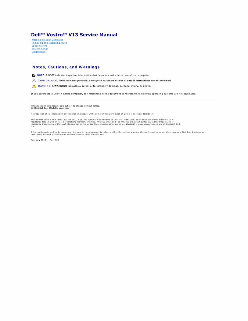
System Setup Screens
Use the following keys to navigate through System Setup screens:
CAUTION: Unless you are an expert computer user, do not change the settings for this program. Certain changes can make your computer work incorrectly.
NOTE: The F2 prompt indicates that the keyboard has initialized. This prompt can appear very quickly, so you must watch for it to display, and then press <F2>. If you press <F2> before you are prompted, this keystroke will be lost.
Menu — Appears on top of the System Setup window. This field provides a menu to access to the System Setup options. Press <\xdf >and< >keys to navigate. As a Menu option is highlighted, the Options List, lists the options that define the hardware installed on you computer.
Options List — Appears on the left side of the System Setup window. The field lists features that define the configuration of your computer, including installed hardware, power conservation, and security features.
Scroll up and down the list with the up- and down-arrow keys. As an option is highlighted, the Options Field displays the option's current and available settings.
Options Field — Appears on the right side of Options List and contains information about each option listed in the Options List. In this field you can view information about your computer and make changes to your current settings.
Press <Enter> to make changes to your current settings. Press <ESC> to return to the Options List.
NOTE: Not all settings listed in the Options Field are changeable.
Help — Appears on the right side of the System Setup window and contains help information about the option selected in Options List.
Key Functions — Appears below the Options Field and lists keys and their functions within the active system setup field.
Keystroke Action
< F2 > Displays information on any selected item in the System Setup.
< Esc >Exit from current view or switch the current view to the Exit page in the System Setup.
< Up Arrow > or < Down Arrow >
Select an item to display.
< Left Arrow > or < Right Arrow >
Select a menu to display.
– or + Change existing item value.
< Enter > Select the sub menu or execute command.
< F9 > Load setup default.
< F10 > Save current configuration and exit System Setup.
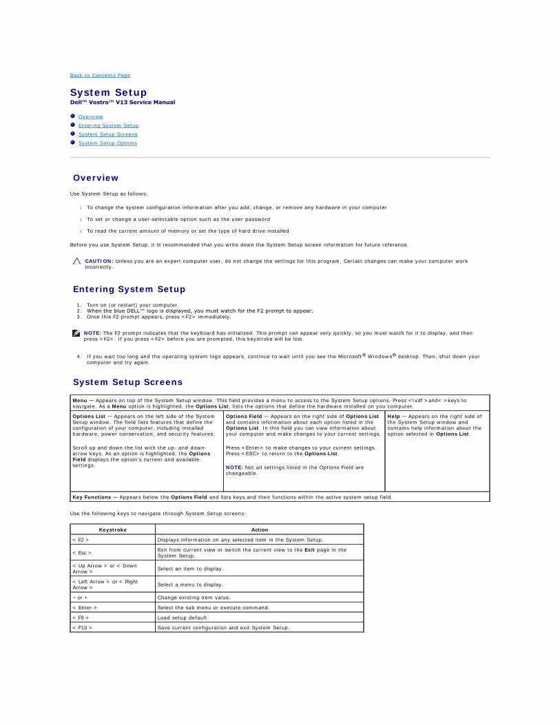
System Setup Options
Main
The Main tab lists out the primary hardware features of the computer. The table below defines the function of each option.
Advanced
The Advanced tab allows you to set various boot and DOS-mode functions. The table below defines the function of each option and its default value.
Security
The Security tab displays the security status and allows you to manage the security features of the computer.
Main
System Time Resets the time on the computer's internal clock.
System Date Resets the time on the computer's internal calendar.
Bios Version Display the BIOS revision.
CPU Type Displays the type of processor.
CPU Speed Displays the speed of the processor.
CPU Cache Size Displays the processor cache size.
CPU ID Displays the processor ID.
Product Name Displays the computer model name.
Fixed HDD Displays the model number of the hard drive.
HDD Size Displays the size of the hard drive.
System Memory Displays the total computer memory.
Extended Memory Displays the total extended memory.
Memory speed Displays the memory speed.
AC Adapter Type Displays the type of the AC adapter.
Advanced
Boot-time Diagnostic ScreenEnable or disable the system information from being displayed on the screen during power-on self test (POST)
Default: Disabled
QuickBoot ModeAllows the System Setup to skip certain tests during POST which decreases the amount of time needed to boot the computer.
Default: Enabled
Intel® SpeedStep™ TechnologyAllows the clock speed of the processor to be dynamically changed by software while minimizing power draw and heat dissipation.
Default: Enabled
No-Execute Mode Memory
ProtectionAllows increased protection against buffer overflow attacks.
Default: Enabled
Intel® Virtualization Technology
Allows a platform to run multiple operating systems and applications in independent partitions, allowing one computer to function as multiple virtual computers.
Default: Disabled
Integrated NICEnable or disable the power supply to the on–board NIC
Default: Enabled
WLAN Control Enable or disable the wireless LAN module. Default: Enabled
WWAN Control Enable or disable the wireless WAN module. Default: Enabled
Bluetooth Enable or disable the Bluetooth module. Default: Enabled
USB Outside Ports Enable or disable the the USB ports. Default: Enabled
USB BIOS Legacy SupportEnable or disable the legacy support for the USB controllers
Default: Enabled
USB Wake SupportAllow USB devices to wake-up the computer from standby. This feature is enabled only when the AC adapter is connected.
Default: Enabled
ExpressCard Enable or disable the ExpressCard slot. Default: Enabled
Card Reader Enable or disable the Card Reader slot. Default: Enabled
Wake On LANAllows the computer to remotely turned on. This feature is enabled only when the AC adapter is connected.
Default: Enabled
SATA Mode SelectionChange the SATA controller mode to either ATA or AHCI.
Default: AHCI
Camera Control Enable or disable the Camera. Default: Enabled
Microphone Control Enable or disable the Microphone. Default: Enabled
Keyboard Click Enable or disable the keyboard sound. Default: Disabled
Boot
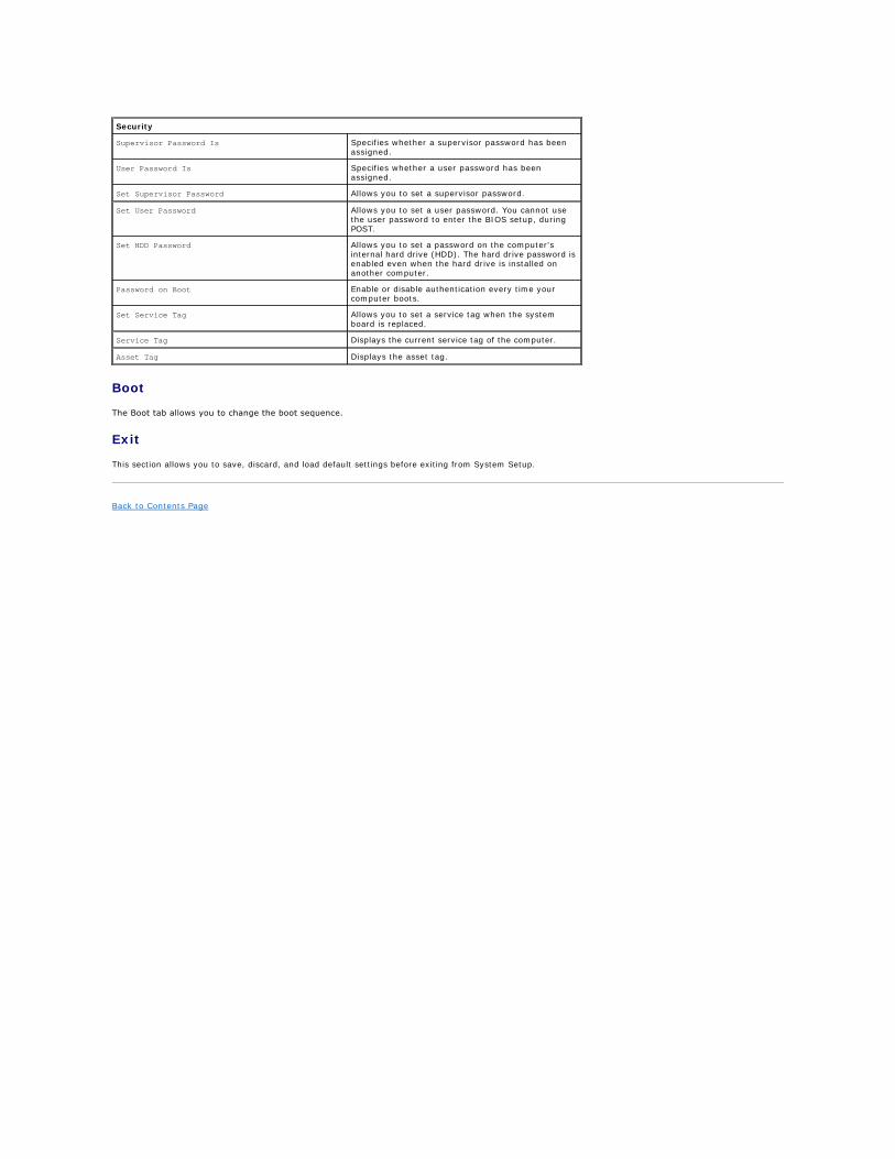
The Boot tab allows you to change the boot sequence.
Exit
This section allows you to save, discard, and load default settings before exiting from System Setup.
Back to Contents Page
Security
Supervisor Password Is Specifies whether a supervisor password has been assigned.
User Password Is Specifies whether a user password has been assigned.
Set Supervisor Password Allows you to set a supervisor password.
Set User Password Allows you to set a user password. You cannot use the user password to enter the BIOS setup, during POST.
Set HDD Password Allows you to set a password on the computer's internal hard drive (HDD). The hard drive password is enabled even when the hard drive is installed on another computer.
Password on Boot Enable or disable authentication every time your computer boots.
Set Service Tag Allows you to set a service tag when the system board is replaced.
Service Tag Displays the current service tag of the computer.
Asset Tag Displays the asset tag.
Back to Contents Page
Diagnostics Dell™ Vostro™ V13 Service Manual
Device Status Lights
Battery Status Lights
Keyboard Status Lights
LED Error Codes
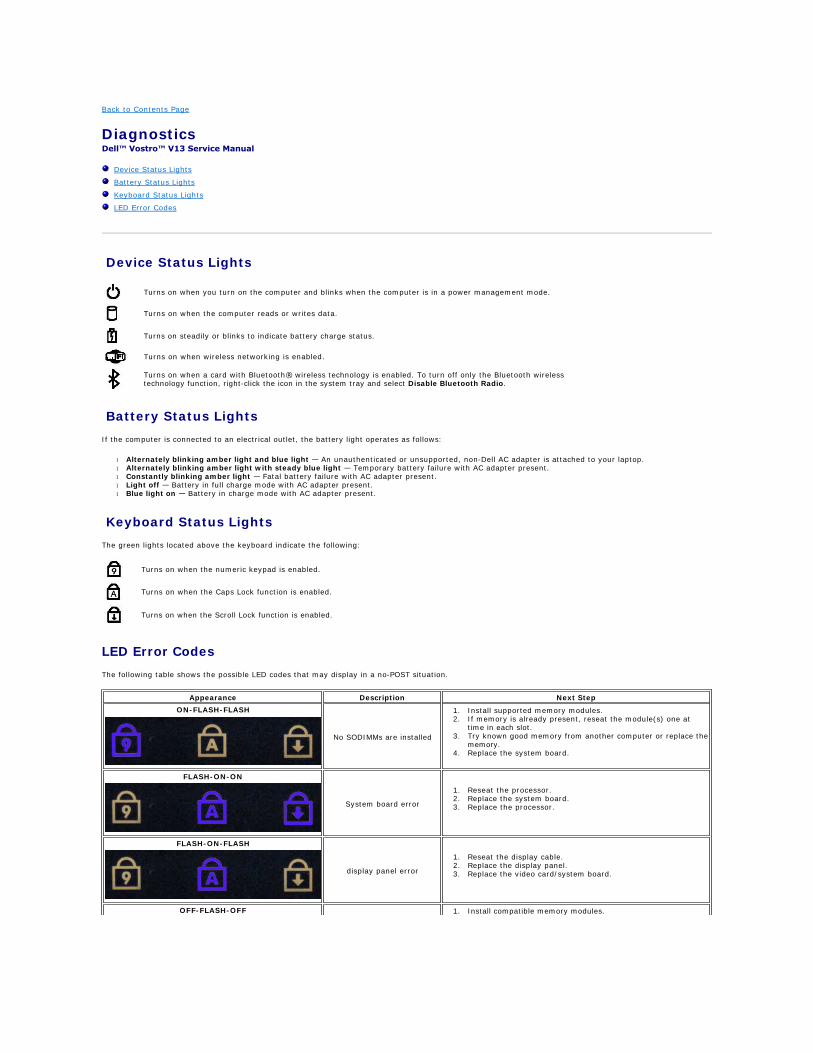
Device Status Lights
Battery Status Lights
If the computer is connected to an electrical outlet, the battery light operates as follows:
l Alternately blinking amber light and blue light — An unauthenticated or unsupported, non-Dell AC adapter is attached to your laptop. l Alternately blinking amber light with steady blue light — Temporary battery failure with AC adapter present. l Constantly blinking amber light — Fatal battery failure with AC adapter present. l Light off — Battery in full charge mode with AC adapter present. l Blue light on — Battery in charge mode with AC adapter present.
Keyboard Status Lights
The green lights located above the keyboard indicate the following:
LED Error Codes
The following table shows the possible LED codes that may display in a no-POST situation.
Turns on when you turn on the computer and blinks when the computer is in a power management mode.
Turns on when the computer reads or writes data.
Turns on steadily or blinks to indicate battery charge status.
Turns on when wireless networking is enabled.
Turns on when a card with Bluetooth® wireless technology is enabled. To turn off only the Bluetooth wireless technology function, right-click the icon in the system tray and select Disable Bluetooth Radio.
Turns on when the numeric keypad is enabled.
Turns on when the Caps Lock function is enabled.
Turns on when the Scroll Lock function is enabled.
Appearance Description Next Step
ON-FLASH-FLASH
No SODIMMs are installed
1. Install supported memory modules. 2. If memory is already present, reseat the module(s) one at
time in each slot. 3. Try known good memory from another computer or replace the
memory. 4. Replace the system board.
FLASH-ON-ON
System board error
1. Reseat the processor. 2. Replace the system board. 3. Replace the processor.
FLASH-ON-FLASH
display panel error
1. Reseat the display cable. 2. Replace the display panel. 3. Replace the video card/system board.
OFF-FLASH-OFF 1. Install compatible memory modules.
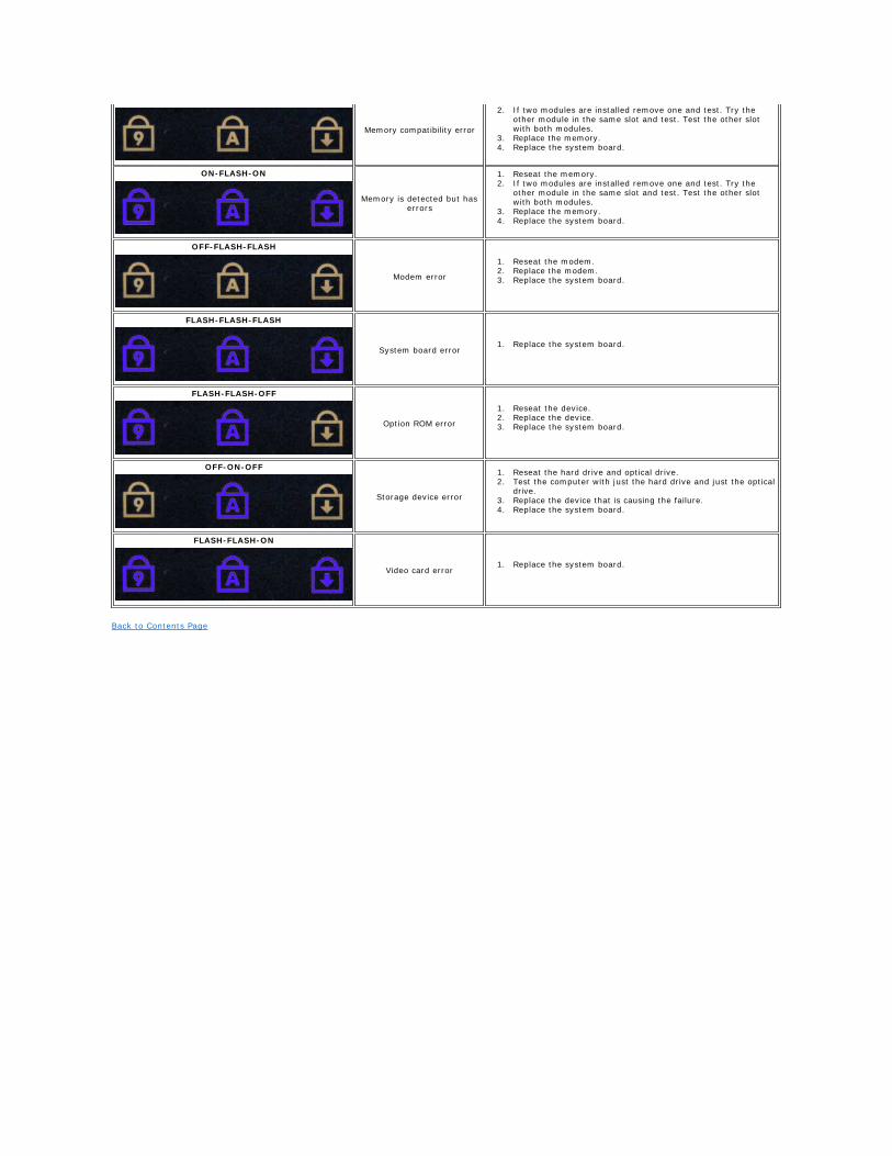
Back to Contents Page
Memory compatibility error
2. If two modules are installed remove one and test. Try the other module in the same slot and test. Test the other slot with both modules.
3. Replace the memory. 4. Replace the system board.
ON-FLASH-ON
Memory is detected but has errors
1. Reseat the memory. 2. If two modules are installed remove one and test. Try the
other module in the same slot and test. Test the other slot with both modules.
3. Replace the memory. 4. Replace the system board.
OFF-FLASH-FLASH
Modem error
1. Reseat the modem. 2. Replace the modem. 3. Replace the system board.
FLASH-FLASH-FLASH
System board error1. Replace the system board.
FLASH-FLASH-OFF
Option ROM error
1. Reseat the device. 2. Replace the device. 3. Replace the system board.
OFF-ON-OFF
Storage device error
1. Reseat the hard drive and optical drive. 2. Test the computer with just the hard drive and just the optical
drive. 3. Replace the device that is causing the failure. 4. Replace the system board.
FLASH-FLASH-ON
Video card error1. Replace the system board.
Back to Contents Page
Removing and Replacing Parts Dell™ Vostro™ V13 Service Manual
Back to Contents Page
ExpressCard
Subscriber Identity Module (SIM) Card
Base Cover
Wireless Local Area Network (WLAN) Card
Hard Drive and Audio Board
Speaker
Memory
Coin-Cell Battery
Heat Sink and Fan Assembly
Display Panel
Palm Rest and Display Assembly
Hard Drive Cable Kit
Secure Digital (SD) Card
Battery
SIM Card Reader
Display Closure Sensor
LED Cover
Keyboard
ExpressCard/SD Card Reader
System Board
Internal Card With Bluetooth® Wireless Technology
Display Bezel
Camera
Back to Contents Page
Specifications Dell™ Vostro™ Service Manual
NOTE: Offerings may vary by region. For more information regarding the configuration of your computer, click Start® Help and Support and select the
option to view information about your computer.
System Information
Memory
Audio
ExpressCard
Display
Touch Pad
AC Adapter
Environmental
Processor
Video
Communications
Ports and Connectors
Keyboard
Battery
Physical
System Information
Chipset Mobile Intel® GS45 Express Chipset
DRAM bus width 64-bit buses
Processor address bus width 36 bits
Flash EPROM SPI 16 Mbits
PCI bus 32 bits, 33 MHz
Processor
Types Intel® Celeron® Ultra Low Voltage (ULV) Intel Core™2 Solo ULV Intel Core2 Duo ULV
L2 cache Intel Celeron ULV–1MB Intel Core2 Solo ULV–3 MB Intel Core2 Duo ULV–3 MB
External bus frequency 800 MHz
Memory
Type DDR3 SDRAM
Speed 1067 MHz
NOTE: The memory runs at 800 MHz due to the limitations of the Front Side Bus (FSB).
Connectors one user-accessible SODIMM socket
Module capacities 1 GB, 2 GB, and 4 GB
Minimum memory 1 GB
Maximum memory 4 GB
Video
Type integrated on system board
Controller and memory Intel GMA X4500HD
Output 15-pin VGA connector
Audio
Type two-channel high definition audio
Controller Realtek ALC269
Stereo conversion 24-bit (analog-to-digital and digital-to-analog)
Interface:
Internal high definition audio
External microphone-in connector, stereo headphones/external speakers connector
Speakers 1.5 W mono
Internal speaker amplifier 1.5 W mono
Volume controls keyboard function keys, program menus
Communications
Network adapter 10/100/1000 Mbps Ethernet LAN
Wireless dedicated WLAN, WWAN, and Bluetooth® wireless support if optional cards are purchased.
ExpressCard
NOTE: The ExpressCard slot does NOT support PC Cards.
ExpressCard connector ExpressCard slot
Cards supported 34-mm ExpressCards
Ports and Connectors
Audio microphone connector, stereo headphone/ speakers connector
Video 15-pin VGA connector
Network adapter RJ-45 connector
USB one 4-pin USB 2.0-compliant connector, one eSATA/USB 2.0-compliant connector
Memory card reader 5-in-1 memory card reader
Mini-Card PCI-E Half-Mini Card support for WLAN PCI-E Full-Mini Card support for WWAN
Display
Type White Light Emitting Diode (WLED) display
Size 13.3 inch high definition (HD)
Active area (X/Y) 293.4 mm x 165.0 mm
Dimensions:
Height 188.8 mm (7.43 inch)
Width 314.1 mm (12.37 inch)
Diagonal 337.8 mm (13.3 inch)
Maximum resolution 1366 x 768 at 262 K colors
Maximum brightness 200 nits
Operating angle 0° (closed) to 135°
Refresh rate 60 Hz
Viewing angles:
Horizontal 40/40
Vertical 15/30
Pixel pitch 0.2148 mm
Keyboard
Number of keys United States: 86 keys
United Kingdom: 87 keys
Brazil: 87 keys
Japan: 90 keys
Layout QWERTY/AZERTY/Kanji
Touchpad
Active area:
X-axis 80.0 mm
Y-axis 40.7 mm
Battery
Type 6-cell "smart" lithium-ion (30 WHr)
Charge time with computer off approximately 4 hours (on a fully discharged battery)
Operating time battery operating time varies depending on operating conditions and can significantly reduce under certain power-intensive conditions.
Life span approximately 300 charge/discharge cycles
Dimensions:
Depth 155.20 mm (6.11 inch)
Height 5.65 mm (0.23 inch)
Width 177.60 mm (6.99 inch)
Voltage 11.10 VDC
Temperature range:
Operating 0 °C to 35 °C (32 °F to 95 °F)
Storage –40 °C to 65 °C (–40 °F to 149 °F)
Coin-cell battery 3 V CR2032 lithium
AC Adapter
Type
Input voltage 100–240 VAC
Input current (maximum) 1.5 A
Input frequency 50–60 Hz
Output current 4.34 A (maximum at 4-second pulse) 3.34 A (continuous)
Output voltage 19.5 +/– 1.0 VDC
Dimensions:
Height 16 mm (0.63 inch)
Width 66 mm (2.60 inch)
Depth 127 mm (5.00 inch)
Temperature range:
Operating 0° C to 35° C (32° F to 95° F)
Storage –40 °C to 65 °C (–40 °F to 149 °F)
Physical
Height (front to back) 16.5 mm to 19.7 mm (0.65 inch to 0.78 inch)
Width 330 mm (12.99 inch)
Depth 230 mm (9.05 inch)
Weight (with 6-cell battery) <1.6 kg (<3.53 lb)
Environmental
Temperature range:
Operating 0° C to 35° C (32° F to 95° F)
Storage –40° C to 65° C (–40° F to 149° F)
Relative humidity (maximum):
Operating 10% to 90% (noncondensing)
Storage 5% to 95% (noncondensing)
Maximum vibration:
Operating 0.66 Grms (2–600 Hz)
Storage 1.30 Grms (2–600 Hz)
NOTE: Vibration is measured using a random-vibration spectrum that simulates user environment.
Maximum shock:
Operating 142 G (2 ms)
Storage 162 G (2 ms)

Back to Contents Page
NOTE: Shock is measured with hard drive in head-parked position and a 2-ms half-sine pulse.
Altitude:
Operating –15.2 m to 3048 m (–50 ft to 10,000 ft)
Storage –15.2 m to 10,668 m (–50 ft to 35,000 ft)
Airborne contaminant level G2 or lower as defined by ANSI/ISA-S71.04-1985
Back to Contents Page
Hard Drive and Audio Board Dell Vostro™ V13 Service Manual
Removing the Hard Drive and Audio Board
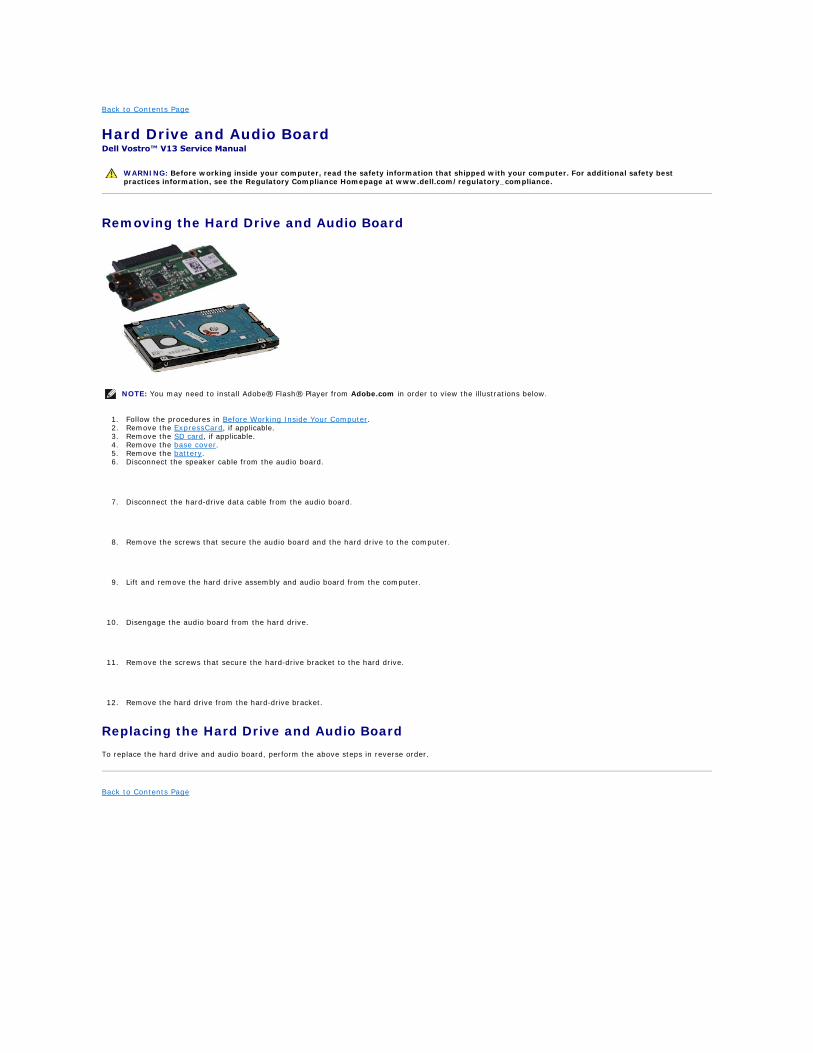
1. Follow the procedures in Before Working Inside Your Computer. 2. Remove the ExpressCard, if applicable. 3. Remove the SD card, if applicable. 4. Remove the base cover. 5. Remove the battery. 6. Disconnect the speaker cable from the audio board.
7. Disconnect the hard-drive data cable from the audio board.
8. Remove the screws that secure the audio board and the hard drive to the computer.
9. Lift and remove the hard drive assembly and audio board from the computer.
10. Disengage the audio board from the hard drive.
11. Remove the screws that secure the hard-drive bracket to the hard drive.
12. Remove the hard drive from the hard-drive bracket.
Replacing the Hard Drive and Audio Board
To replace the hard drive and audio board, perform the above steps in reverse order.
Back to Contents Page
WARNING: Before working inside your computer, read the safety information that shipped with your computer. For additional safety best practices information, see the Regulatory Compliance Homepage at www.dell.com/regulatory_compliance.
NOTE: You may need to install Adobe® Flash® Player from Adobe.com in order to view the illustrations below.
Back to Contents Page
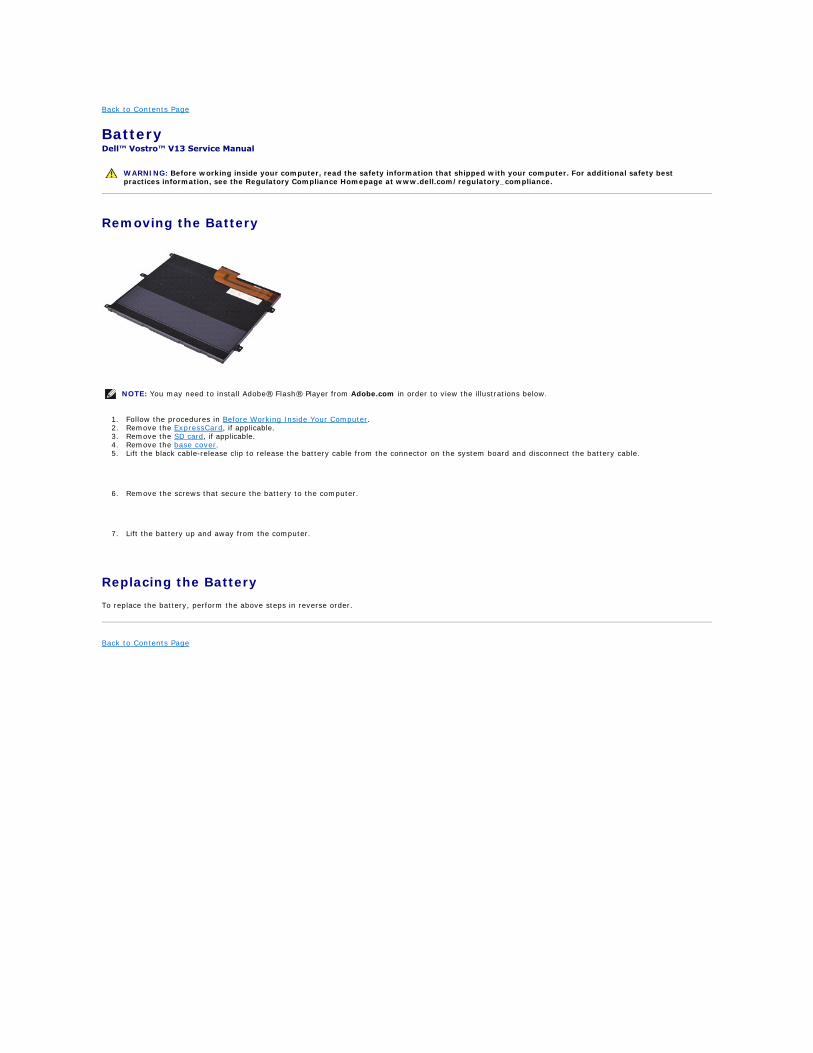
Battery Dell™ Vostro™ V13 Service Manual
Removing the Battery
1. Follow the procedures in Before Working Inside Your Computer. 2. Remove the ExpressCard, if applicable. 3. Remove the SD card, if applicable. 4. Remove the base cover. 5. Lift the black cable-release clip to release the battery cable from the connector on the system board and disconnect the battery cable.
6. Remove the screws that secure the battery to the computer.
7. Lift the battery up and away from the computer.
Replacing the Battery
To replace the battery, perform the above steps in reverse order.
Back to Contents Page
WARNING: Before working inside your computer, read the safety information that shipped with your computer. For additional safety best practices information, see the Regulatory Compliance Homepage at www.dell.com/regulatory_compliance.
NOTE: You may need to install Adobe® Flash® Player from Adobe.com in order to view the illustrations below.
Back to Contents Page
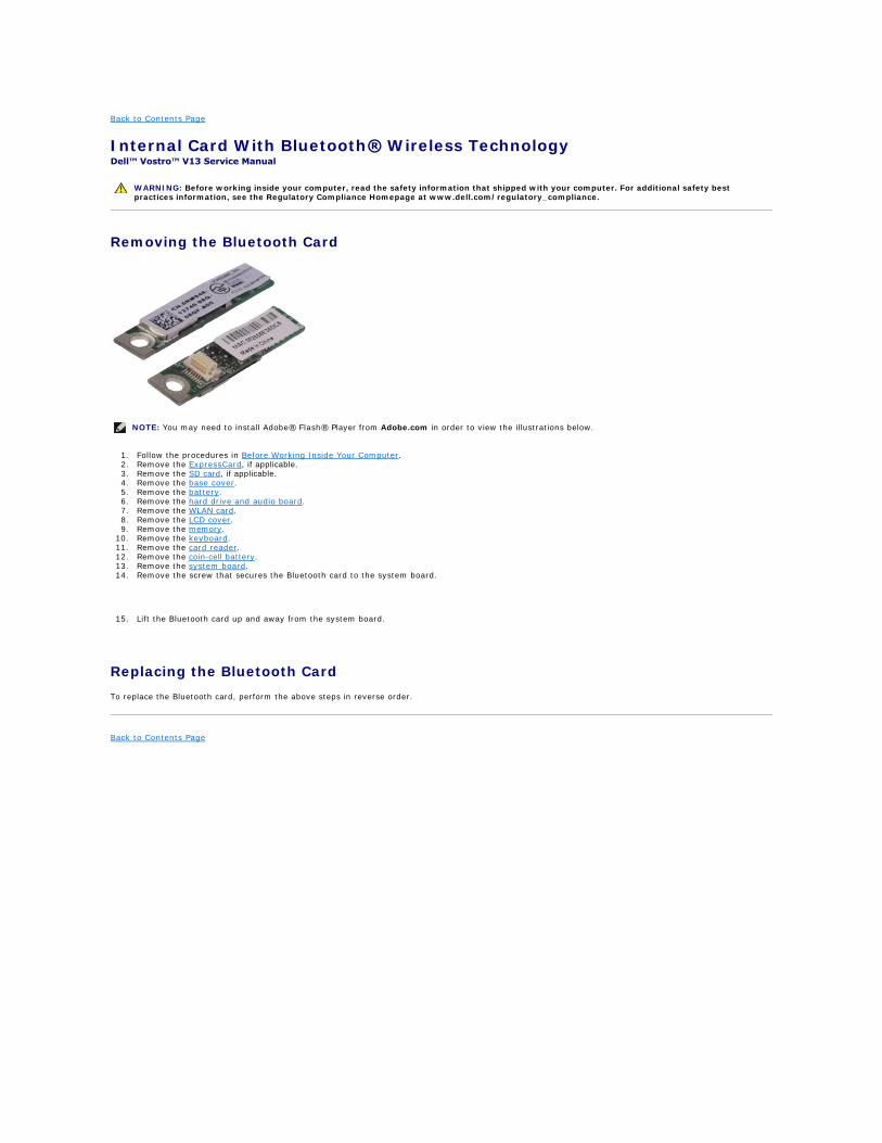
Internal Card With Bluetooth® Wireless Technology Dell™ Vostro™ V13 Service Manual
Removing the Bluetooth Card
1. Follow the procedures in Before Working Inside Your Computer. 2. Remove the ExpressCard, if applicable. 3. Remove the SD card, if applicable. 4. Remove the base cover. 5. Remove the battery. 6. Remove the hard drive and audio board. 7. Remove the WLAN card. 8. Remove the LCD cover. 9. Remove the memory.
10. Remove the keyboard. 11. Remove the card reader. 12. Remove the coin-cell battery. 13. Remove the system board. 14. Remove the screw that secures the Bluetooth card to the system board.
15. Lift the Bluetooth card up and away from the system board.
Replacing the Bluetooth Card
To replace the Bluetooth card, perform the above steps in reverse order.
Back to Contents Page
WARNING: Before working inside your computer, read the safety information that shipped with your computer. For additional safety best practices information, see the Regulatory Compliance Homepage at www.dell.com/regulatory_compliance.
NOTE: You may need to install Adobe® Flash® Player from Adobe.com in order to view the illustrations below.
Back to Contents Page
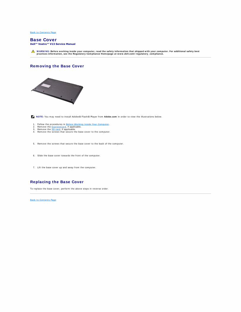
Base Cover Dell™ Vostro™ V13 Service Manual
Removing the Base Cover
1. Follow the procedures in Before Working Inside Your Computer. 2. Remove the ExpressCard, if applicable. 3. Remove the SD card, if applicable. 4. Remove the screws that secure the base cover to the computer.
5. Remove the screws that secure the base cover to the back of the computer.
6. Slide the base cover towards the front of the computer.
7. Lift the base cover up and away from the computer.
Replacing the Base Cover
To replace the base cover, perform the above steps in reverse order.
Back to Contents Page
WARNING: Before working inside your computer, read the safety information that shipped with your computer. For additional safety best practices information, see the Regulatory Compliance Homepage at www.dell.com/regulatory_compliance.
NOTE: You may need to install Adobe® Flash® Player from Adobe.com in order to view the illustrations below.
Back to Contents Page
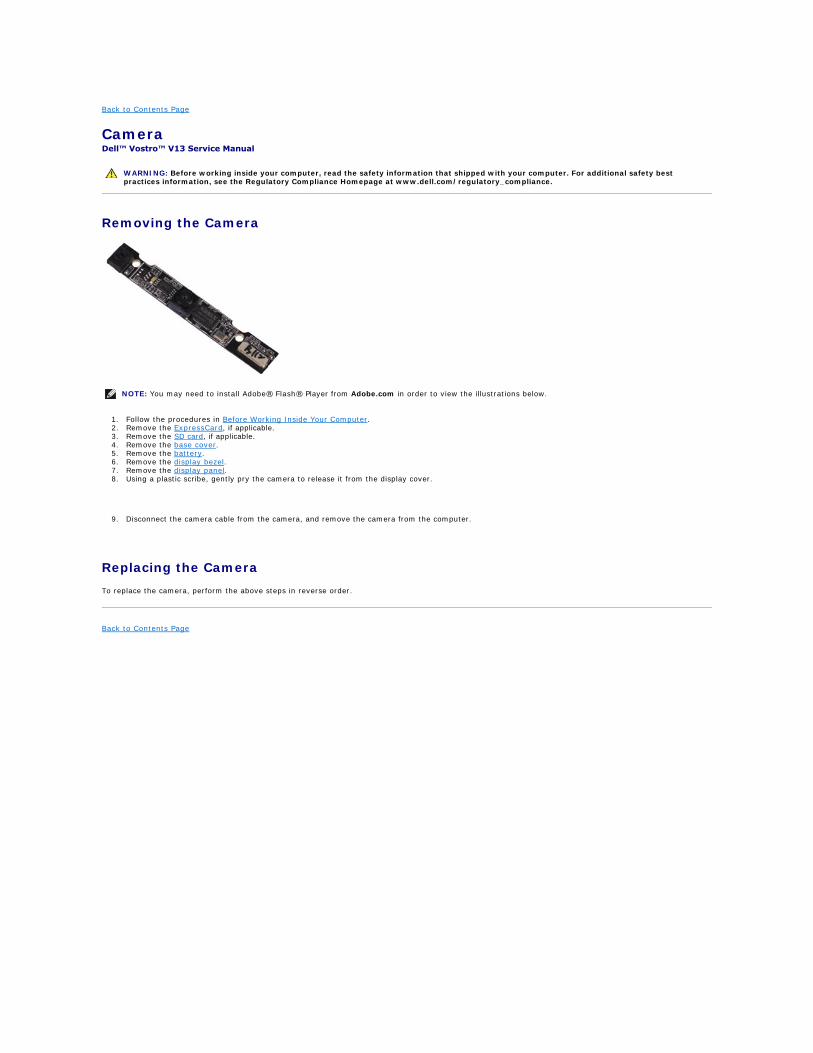
Camera Dell™ Vostro™ V13 Service Manual
Removing the Camera
1. Follow the procedures in Before Working Inside Your Computer. 2. Remove the ExpressCard, if applicable. 3. Remove the SD card, if applicable. 4. Remove the base cover. 5. Remove the battery. 6. Remove the display bezel. 7. Remove the display panel. 8. Using a plastic scribe, gently pry the camera to release it from the display cover.
9. Disconnect the camera cable from the camera, and remove the camera from the computer.
Replacing the Camera
To replace the camera, perform the above steps in reverse order.
Back to Contents Page
WARNING: Before working inside your computer, read the safety information that shipped with your computer. For additional safety best practices information, see the Regulatory Compliance Homepage at www.dell.com/regulatory_compliance.
NOTE: You may need to install Adobe® Flash® Player from Adobe.com in order to view the illustrations below.
Back to Contents Page
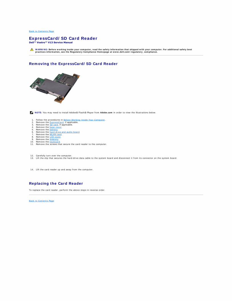
ExpressCard/SD Card Reader Dell™ Vostro™ V13 Service Manual
Removing the ExpressCard/SD Card Reader
1. Follow the procedures in Before Working Inside Your Computer. 2. Remove the ExpressCard, if applicable. 3. Remove the SD card, if applicable. 4. Remove the base cover. 5. Remove the battery. 6. Remove the hard drive and audio board. 7. Remove the WLAN card. 8. Remove the LCD cover. 9. Remove the memory.
10. Remove the keyboard. 11. Remove the screws that secure the card reader to the computer.
12. Carefully turn over the computer. 13. Lift the clip that secures the hard-drive data cable to the system board and disconnect it from its connector on the system board.
14. Lift the card reader up and away from the computer.
Replacing the Card Reader
To replace the card reader, perform the above steps in reverse order.
Back to Contents Page
WARNING: Before working inside your computer, read the safety information that shipped with your computer. For additional safety best practices information, see the Regulatory Compliance Homepage at www.dell.com/regulatory_compliance.
NOTE: You may need to install Adobe® Flash® Player from Adobe.com in order to view the illustrations below.
Back to Contents Page
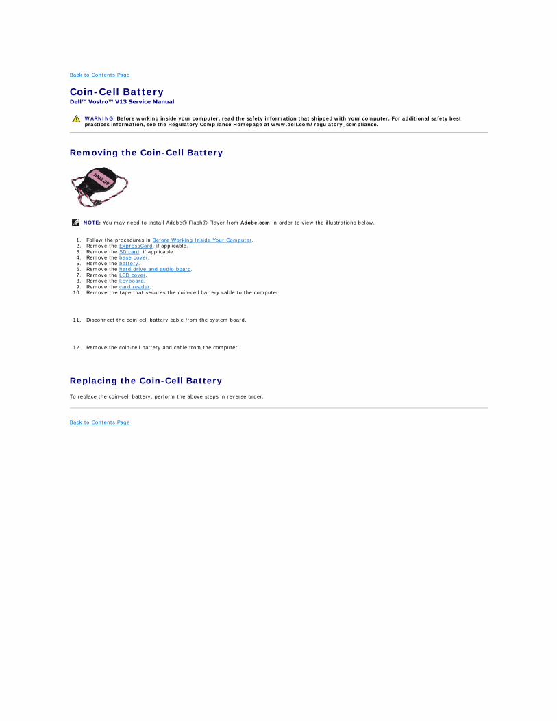
Coin-Cell Battery Dell™ Vostro™ V13 Service Manual
Removing the Coin-Cell Battery
1. Follow the procedures in Before Working Inside Your Computer. 2. Remove the ExpressCard, if applicable. 3. Remove the SD card, if applicable. 4. Remove the base cover. 5. Remove the battery. 6. Remove the hard drive and audio board. 7. Remove the LCD cover. 8. Remove the keyboard. 9. Remove the card reader.
10. Remove the tape that secures the coin-cell battery cable to the computer.
11. Disconnect the coin-cell battery cable from the system board.
12. Remove the coin-cell battery and cable from the computer.
Replacing the Coin-Cell Battery
To replace the coin-cell battery, perform the above steps in reverse order.
Back to Contents Page
WARNING: Before working inside your computer, read the safety information that shipped with your computer. For additional safety best practices information, see the Regulatory Compliance Homepage at www.dell.com/regulatory_compliance.
NOTE: You may need to install Adobe® Flash® Player from Adobe.com in order to view the illustrations below.
Back to Contents Page
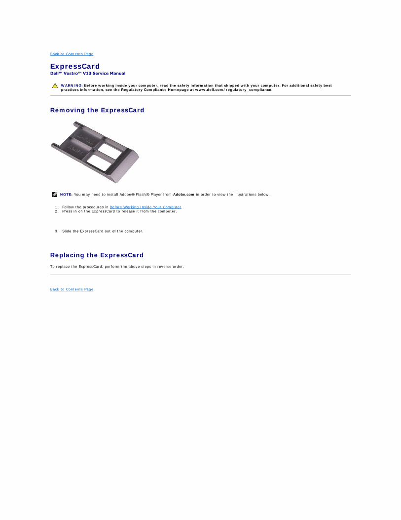
ExpressCard Dell™ Vostro™ V13 Service Manual
Removing the ExpressCard
1. Follow the procedures in Before Working Inside Your Computer. 2. Press in on the ExpressCard to release it from the computer.
3. Slide the ExpressCard out of the computer.
Replacing the ExpressCard
To replace the ExpressCard, perform the above steps in reverse order.
Back to Contents Page
WARNING: Before working inside your computer, read the safety information that shipped with your computer. For additional safety best practices information, see the Regulatory Compliance Homepage at www.dell.com/regulatory_compliance.
NOTE: You may need to install Adobe® Flash® Player from Adobe.com in order to view the illustrations below.
Back to Contents Page
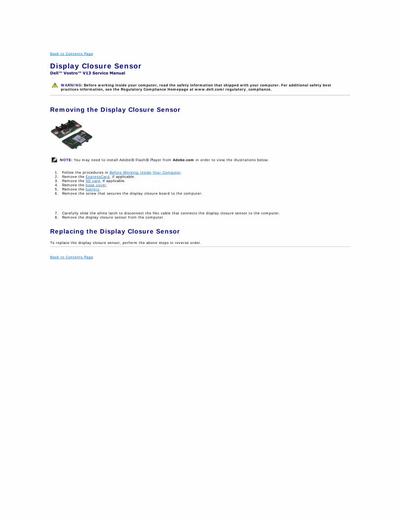
Display Closure Sensor Dell™ Vostro™ V13 Service Manual
Removing the Display Closure Sensor
1. Follow the procedures in Before Working Inside Your Computer. 2. Remove the ExpressCard, if applicable. 3. Remove the SD card, if applicable. 4. Remove the base cover. 5. Remove the battery. 6. Remove the screw that secures the display closure board to the computer.
7. Carefully slide the white latch to disconnect the flex cable that connects the display closure sensor to the computer. 8. Remove the display closure sensor from the computer.
Replacing the Display Closure Sensor
To replace the display closure sensor, perform the above steps in reverse order.
Back to Contents Page
WARNING: Before working inside your computer, read the safety information that shipped with your computer. For additional safety best practices information, see the Regulatory Compliance Homepage at www.dell.com/regulatory_compliance.
NOTE: You may need to install Adobe® Flash® Player from Adobe.com in order to view the illustrations below.
Back to Contents Page
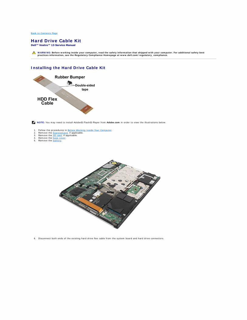
Hard Drive Cable Kit Dell™ Vostro™ 13 Service Manual
Installing the Hard Drive Cable Kit
1. Follow the procedures in Before Working Inside Your Computer. 2. Remove the ExpressCard, if applicable. 3. Remove the SD card, if applicable. 4. Remove the base cover. 5. Remove the battery.
6. Disconnect both ends of the existing hard drive flex cable from the system board and hard drive connectors.
WARNING: Before working inside your computer, read the safety information that shipped with your computer. For additional safety best practices information, see the Regulatory Compliance Homepage at www.dell.com/regulatory_compliance.
NOTE: You may need to install Adobe® Flash® Player from Adobe.com in order to view the illustrations below.
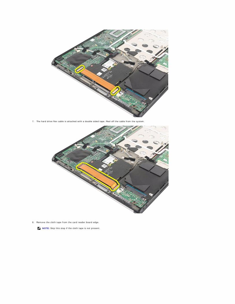
7. The hard drive flex cable is attached with a double sided tape. Peel off the cable from the system.
8. Remove the cloth tape from the card reader board edge.
NOTE: Skip this step if the cloth tape is not present.
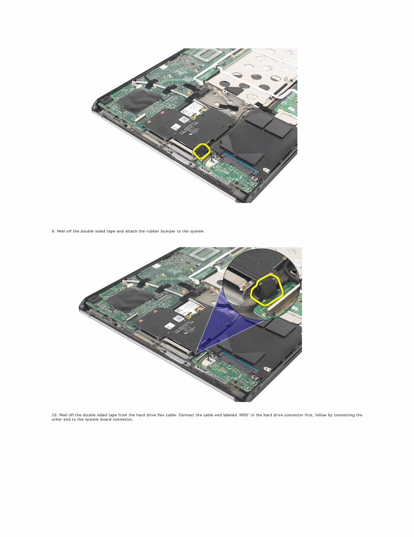
9. Peel off the double sided tape and attach the rubber bumper to the system.
10. Peel off the double sided tape from the hard drive flex cable. Connect the cable end labeled 'HDD' to the hard drive connector first, follow by connecting the other end to the system board connector.
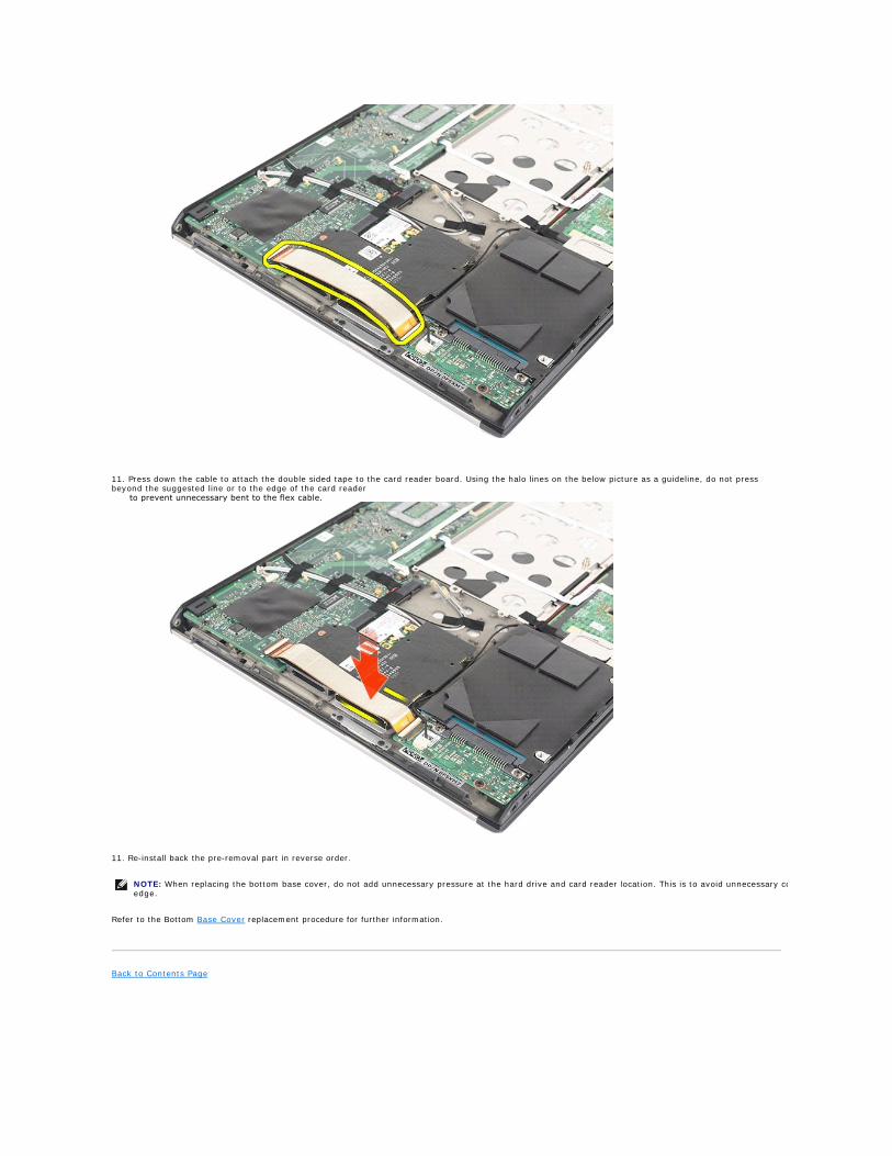
11. Press down the cable to attach the double sided tape to the card reader board. Using the halo lines on the below picture as a guideline, do not press beyond the suggested line or to the edge of the card reader to prevent unnecessary bent to the flex cable.
11. Re-install back the pre-removal part in reverse order.
Refer to the Bottom Base Cover replacement procedure for further information.
Back to Contents Page
NOTE: When replacing the bottom base cover, do not add unnecessary pressure at the hard drive and card reader location. This is to avoid unnecessary contact between the flex cable and the card reader board edge.
Back to Contents Page
Heat Sink and Fan Assembly Dell™ Vostro™ V13 Service Manual
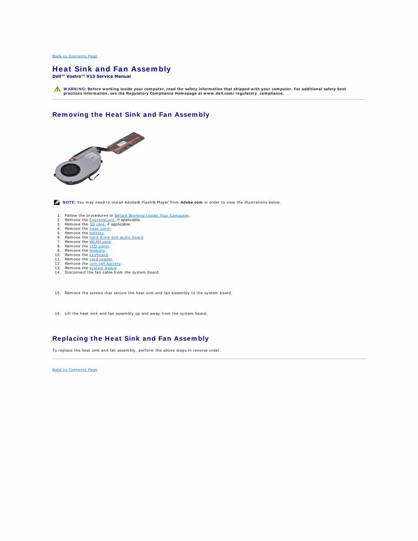
Removing the Heat Sink and Fan Assembly
1. Follow the procedures in Before Working Inside Your Computer. 2. Remove the ExpressCard, if applicable. 3. Remove the SD card, if applicable. 4. Remove the base cover. 5. Remove the battery. 6. Remove the hard drive and audio board. 7. Remove the WLAN card. 8. Remove the LCD cover. 9. Remove the memory.
10. Remove the keyboard. 11. Remove the card reader. 12. Remove the coin-cell battery. 13. Remove the system board. 14. Disconnect the fan cable from the system board.
15. Remove the screws that secure the heat sink and fan assembly to the system board.
16. Lift the heat sink and fan assembly up and away from the system board.
Replacing the Heat Sink and Fan Assembly
To replace the heat sink and fan assembly, perform the above steps in reverse order.
Back to Contents Page
WARNING: Before working inside your computer, read the safety information that shipped with your computer. For additional safety best practices information, see the Regulatory Compliance Homepage at www.dell.com/regulatory_compliance.
NOTE: You may need to install Adobe® Flash® Player from Adobe.com in order to view the illustrations below.
Back to Contents Page
Keyboard Dell™ Vostro™ V13 Service Manual
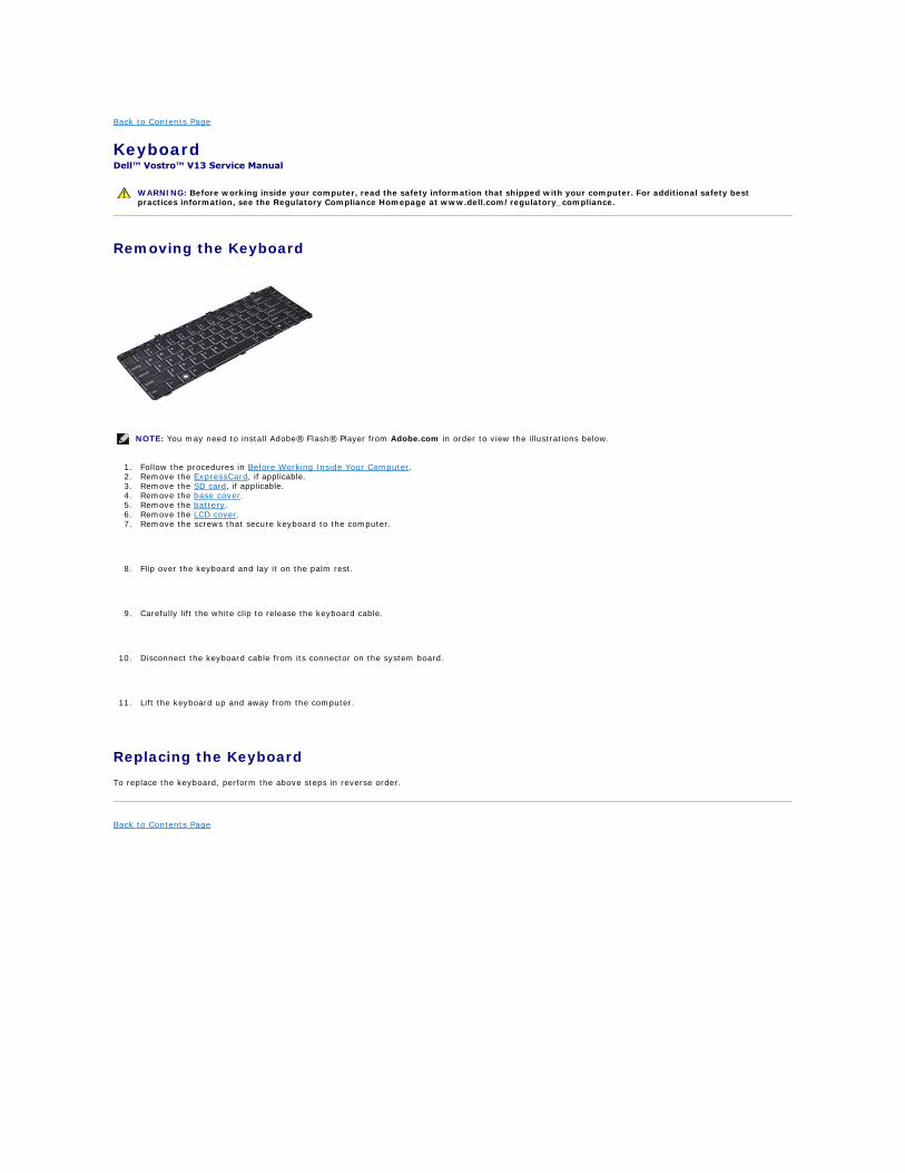
Removing the Keyboard
1. Follow the procedures in Before Working Inside Your Computer. 2. Remove the ExpressCard, if applicable. 3. Remove the SD card, if applicable. 4. Remove the base cover. 5. Remove the battery. 6. Remove the LCD cover. 7. Remove the screws that secure keyboard to the computer.
8. Flip over the keyboard and lay it on the palm rest.
9. Carefully lift the white clip to release the keyboard cable.
10. Disconnect the keyboard cable from its connector on the system board.
11. Lift the keyboard up and away from the computer.
Replacing the Keyboard
To replace the keyboard, perform the above steps in reverse order.
Back to Contents Page
WARNING: Before working inside your computer, read the safety information that shipped with your computer. For additional safety best practices information, see the Regulatory Compliance Homepage at www.dell.com/regulatory_compliance.
NOTE: You may need to install Adobe® Flash® Player from Adobe.com in order to view the illustrations below.

Back to Contents Page
Display Panel Dell™ Vostro™ V13 Service Manual
Removing the Display Panel
1. Follow the procedures in Before Working Inside Your Computer. 2. Remove the ExpressCard, if applicable. 3. Remove the SD card, if applicable. 4. Remove the base cover. 5. Remove the display bezel. 6. Remove the screws that secure the display panel to the display cover.
7. Carefully flip the display panel towards the keyboard.
8. Remove the adhesive tape that secures the display-panel cable to the display cover.
9. Remove the display panel from the computer.
Replacing the Display Panel
To replace the display panel, perform the above steps in reverse order.
Back to Contents Page
WARNING: Before working inside your computer, read the safety information that shipped with your computer. For additional safety best practices information, see the Regulatory Compliance Homepage at www.dell.com/regulatory_compliance.
NOTE: You may need to install Adobe® Flash® Player from Adobe.com in order to view the illustrations below.
Back to Contents Page
Display Bezel Dell™ Vostro™ V13 Service Manual
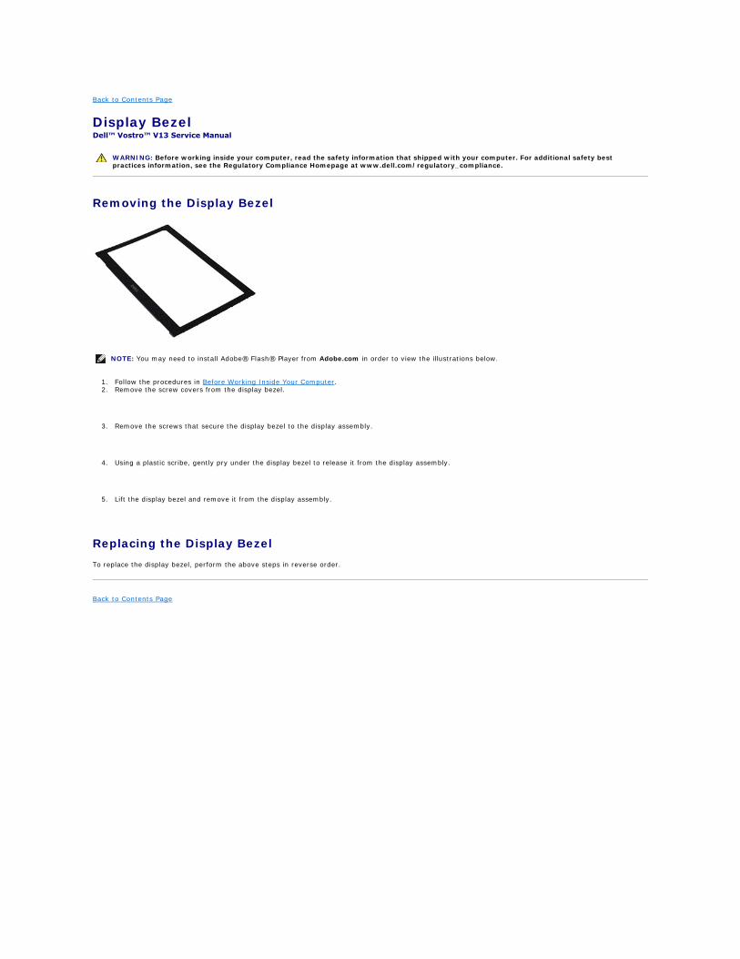
Removing the Display Bezel
1. Follow the procedures in Before Working Inside Your Computer. 2. Remove the screw covers from the display bezel.
3. Remove the screws that secure the display bezel to the display assembly.
4. Using a plastic scribe, gently pry under the display bezel to release it from the display assembly.
5. Lift the display bezel and remove it from the display assembly.
Replacing the Display Bezel
To replace the display bezel, perform the above steps in reverse order.
Back to Contents Page
WARNING: Before working inside your computer, read the safety information that shipped with your computer. For additional safety best practices information, see the Regulatory Compliance Homepage at www.dell.com/regulatory_compliance.
NOTE: You may need to install Adobe® Flash® Player from Adobe.com in order to view the illustrations below.

Back to Contents Page
Memory Dell™ Vostro™ V13 Service Manual
Removing the Memory Module
1. Follow the procedures in Before Working Inside Your Computer. 2. Remove the ExpressCard, if applicable. 3. Remove the SD card, if applicable. 4. Remove the base cover. 5. Remove the battery. 6. Remove the LCD cover. 7. Use your fingertips to carefully spread apart the securing clips on each end of the memory module connector until the memory module pops up.
8. Remove the memory module from its connector on the system board, drawing the module from the system board at a 45-degree angle.
Replacing the Memory Module
1. Place the memory module at a 45-degree angle at the connector on the system board, and align the notch in the module with the tab on the connector.
2. Press down on the module until it clicks into place. If the module does not click into place, remove the module and reinstall it.
Back to Contents Page
WARNING: Before working inside your computer, read the safety information that shipped with your computer. For additional safety best practices information, see the Regulatory Compliance Homepage at www.dell.com/regulatory_compliance.
NOTE: You may need to install Adobe® Flash® Player from Adobe.com in order to view the illustrations below.
Back to Contents Page
Palm Rest and Display Assembly Dell™ Vostro™ V13 Service Manual
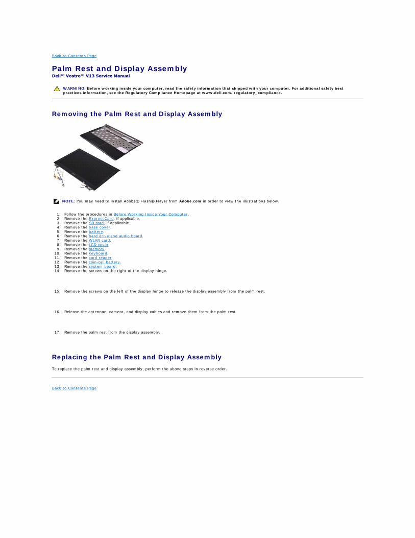
Removing the Palm Rest and Display Assembly
1. Follow the procedures in Before Working Inside Your Computer. 2. Remove the ExpressCard, if applicable. 3. Remove the SD card, if applicable. 4. Remove the base cover. 5. Remove the battery. 6. Remove the hard drive and audio board. 7. Remove the WLAN card. 8. Remove the LCD cover. 9. Remove the memory.
10. Remove the keyboard. 11. Remove the card reader. 12. Remove the coin-cell battery. 13. Remove the system board. 14. Remove the screws on the right of the display hinge.
15. Remove the screws on the left of the display hinge to release the display assembly from the palm rest.
16. Release the antennae, camera, and display cables and remove them from the palm rest.
17. Remove the palm rest from the display assembly.
Replacing the Palm Rest and Display Assembly
To replace the palm rest and display assembly, perform the above steps in reverse order.
Back to Contents Page
WARNING: Before working inside your computer, read the safety information that shipped with your computer. For additional safety best practices information, see the Regulatory Compliance Homepage at www.dell.com/regulatory_compliance.
NOTE: You may need to install Adobe® Flash® Player from Adobe.com in order to view the illustrations below.
Back to Contents Page
LED Cover Dell™ Vostro™ V13 Service Manual
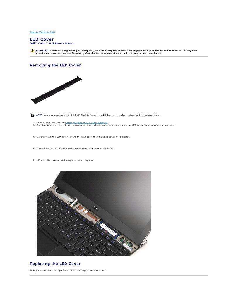
Removing the LED Cover
1. Follow the procedures in Before Working Inside Your Computer. 2. Starting from the right side of the computer, use a plastic scribe to gently pry up the LED cover from the computer chassis.
3. Carefully pull the LED cover toward the keyboard, then flip it up toward the display.
4. Disconnect the LED board cable from its connector on the LED cover.
5. Lift the LED cover up and away from the computer.
Replacing the LED Cover
To replace the LED cover, perform the above steps in reverse order.
WARNING: Before working inside your computer, read the safety information that shipped with your computer. For additional safety best practices information, see the Regulatory Compliance Homepage at www.dell.com/regulatory_compliance.
NOTE: You may need to install Adobe® Flash® Player from Adobe.com in order to view the illustrations below.

Back to Contents Page
Back to Contents Page
Secure Digital (SD) Card Dell™ Vostro™ V13 Service Manual
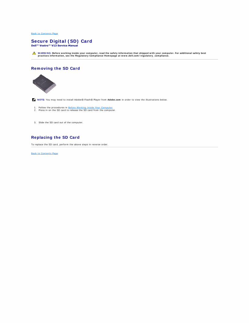
Removing the SD Card
1. Follow the procedures in Before Working Inside Your Computer. 2. Press in on the SD card to release the SD card from the computer.
3. Slide the SD card out of the computer.
Replacing the SD Card
To replace the SD card, perform the above steps in reverse order.
Back to Contents Page
WARNING: Before working inside your computer, read the safety information that shipped with your computer. For additional safety best practices information, see the Regulatory Compliance Homepage at www.dell.com/regulatory_compliance.
NOTE: You may need to install Adobe® Flash® Player from Adobe.com in order to view the illustrations below.
Back to Contents Page
SIM Card Reader Dell™ Vostro™ V13 Service Manual
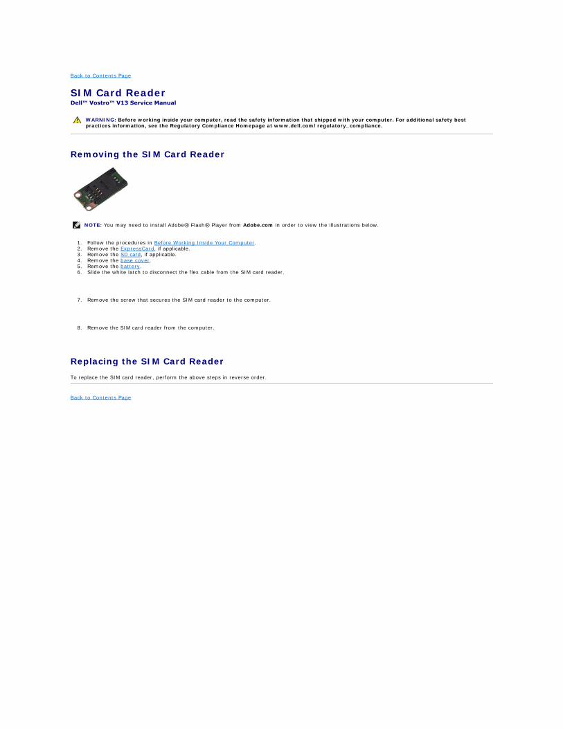
Removing the SIM Card Reader
1. Follow the procedures in Before Working Inside Your Computer. 2. Remove the ExpressCard, if applicable. 3. Remove the SD card, if applicable. 4. Remove the base cover. 5. Remove the battery. 6. Slide the white latch to disconnect the flex cable from the SIM card reader.
7. Remove the screw that secures the SIM card reader to the computer.
8. Remove the SIM card reader from the computer.
Replacing the SIM Card Reader
To replace the SIM card reader, perform the above steps in reverse order.
Back to Contents Page
WARNING: Before working inside your computer, read the safety information that shipped with your computer. For additional safety best practices information, see the Regulatory Compliance Homepage at www.dell.com/regulatory_compliance.
NOTE: You may need to install Adobe® Flash® Player from Adobe.com in order to view the illustrations below.
Back to Contents Page
Subscriber Identity Module (SIM) Card Dell™ Vostro™ V13 Service Manual
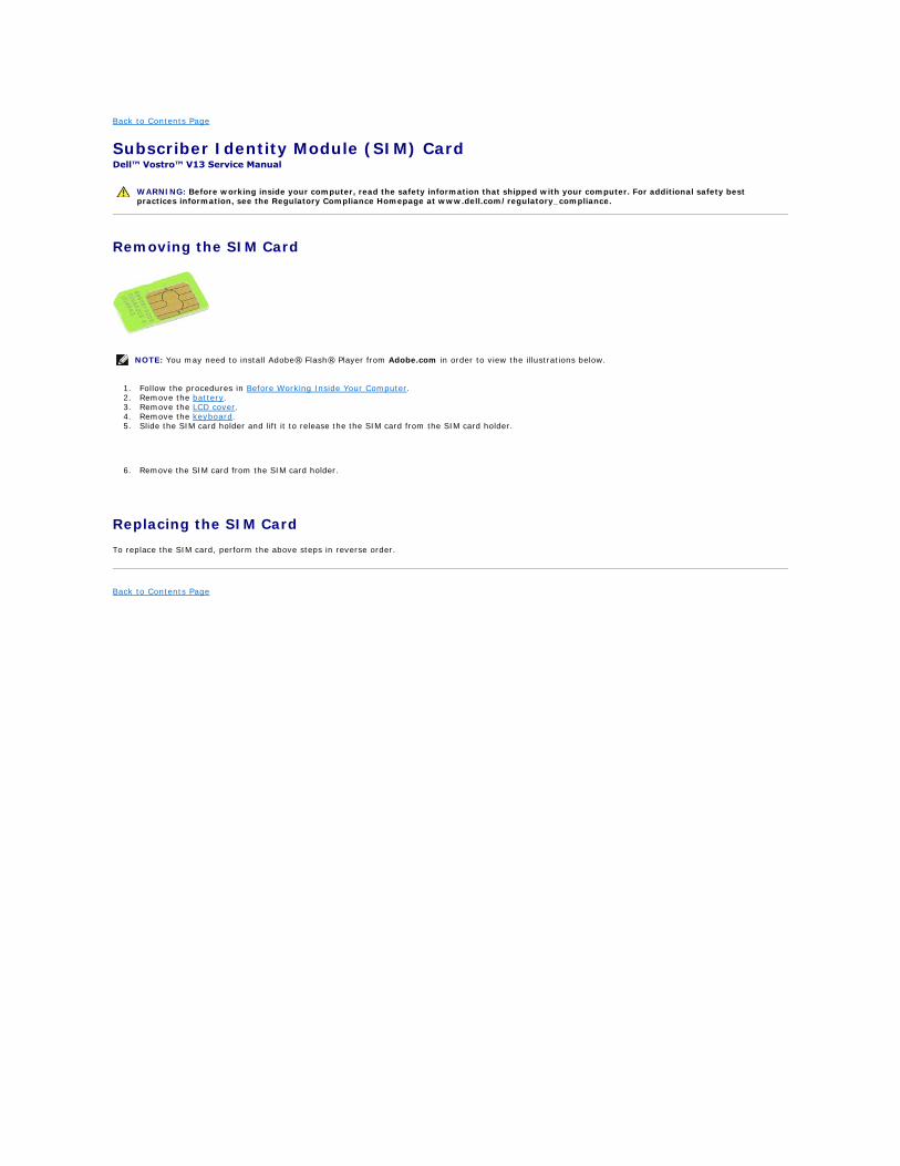
Removing the SIM Card
1. Follow the procedures in Before Working Inside Your Computer. 2. Remove the battery. 3. Remove the LCD cover. 4. Remove the keyboard. 5. Slide the SIM card holder and lift it to release the the SIM card from the SIM card holder.
6. Remove the SIM card from the SIM card holder.
Replacing the SIM Card
To replace the SIM card, perform the above steps in reverse order.
Back to Contents Page
WARNING: Before working inside your computer, read the safety information that shipped with your computer. For additional safety best practices information, see the Regulatory Compliance Homepage at www.dell.com/regulatory_compliance.
NOTE: You may need to install Adobe® Flash® Player from Adobe.com in order to view the illustrations below.
Back to Contents Page
Speaker Dell™ Vostro™ V13 Service Manual
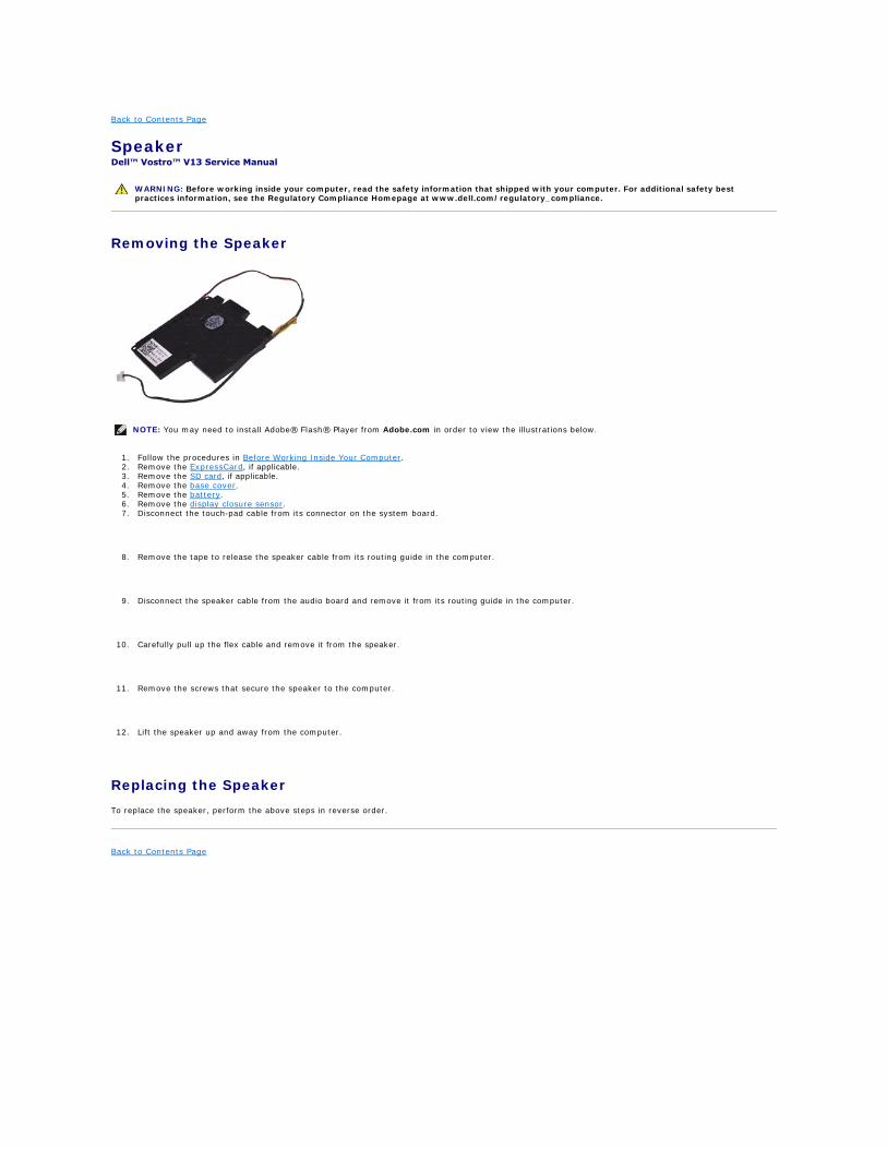
Removing the Speaker
1. Follow the procedures in Before Working Inside Your Computer. 2. Remove the ExpressCard, if applicable. 3. Remove the SD card, if applicable. 4. Remove the base cover. 5. Remove the battery. 6. Remove the display closure sensor. 7. Disconnect the touch-pad cable from its connector on the system board.
8. Remove the tape to release the speaker cable from its routing guide in the computer.
9. Disconnect the speaker cable from the audio board and remove it from its routing guide in the computer.
10. Carefully pull up the flex cable and remove it from the speaker.
11. Remove the screws that secure the speaker to the computer.
12. Lift the speaker up and away from the computer.
Replacing the Speaker
To replace the speaker, perform the above steps in reverse order.
Back to Contents Page
WARNING: Before working inside your computer, read the safety information that shipped with your computer. For additional safety best practices information, see the Regulatory Compliance Homepage at www.dell.com/regulatory_compliance.
NOTE: You may need to install Adobe® Flash® Player from Adobe.com in order to view the illustrations below.
Back to Contents Page
System Board Dell™ Vostro™ V13 Service Manual
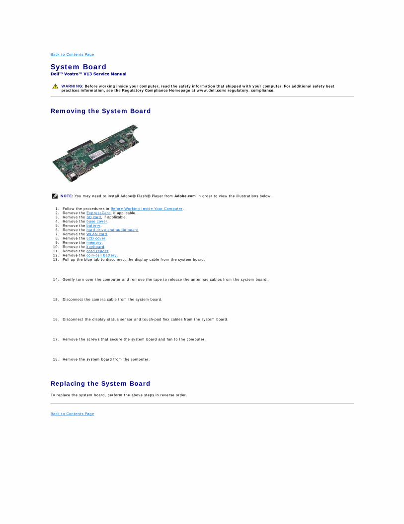
Removing the System Board
1. Follow the procedures in Before Working Inside Your Computer. 2. Remove the ExpressCard, if applicable. 3. Remove the SD card, if applicable. 4. Remove the base cover. 5. Remove the battery. 6. Remove the hard drive and audio board. 7. Remove the WLAN card. 8. Remove the LCD cover. 9. Remove the memory.
10. Remove the keyboard. 11. Remove the card reader. 12. Remove the coin-cell battery. 13. Pull up the blue tab to disconnect the display cable from the system board.
14. Gently turn over the computer and remove the tape to release the antennae cables from the system board.
15. Disconnect the camera cable from the system board.
16. Disconnect the display status sensor and touch-pad flex cables from the system board.
17. Remove the screws that secure the system board and fan to the computer.
18. Remove the system board from the computer.
Replacing the System Board
To replace the system board, perform the above steps in reverse order.
Back to Contents Page
WARNING: Before working inside your computer, read the safety information that shipped with your computer. For additional safety best practices information, see the Regulatory Compliance Homepage at www.dell.com/regulatory_compliance.
NOTE: You may need to install Adobe® Flash® Player from Adobe.com in order to view the illustrations below.
Back to Contents Page
Wireless Local Area Network (WLAN) Card Dell™ Vostro™ V13 Service Manual
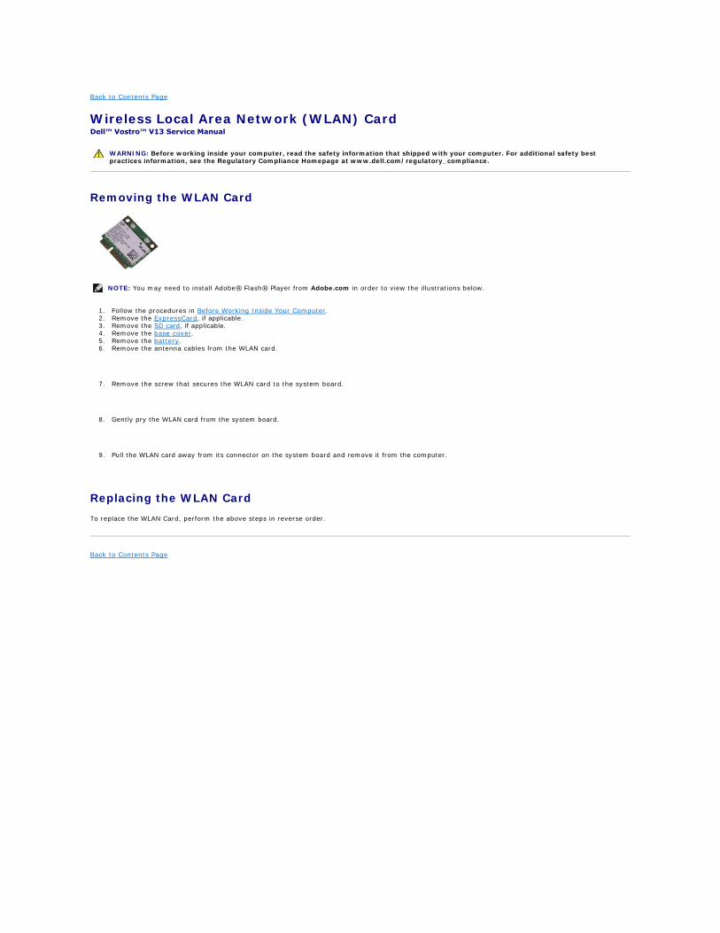
Removing the WLAN Card
1. Follow the procedures in Before Working Inside Your Computer. 2. Remove the ExpressCard, if applicable. 3. Remove the SD card, if applicable. 4. Remove the base cover. 5. Remove the battery. 6. Remove the antenna cables from the WLAN card.
7. Remove the screw that secures the WLAN card to the system board.
8. Gently pry the WLAN card from the system board.
9. Pull the WLAN card away from its connector on the system board and remove it from the computer.
Replacing the WLAN Card
To replace the WLAN Card, perform the above steps in reverse order.
Back to Contents Page
WARNING: Before working inside your computer, read the safety information that shipped with your computer. For additional safety best practices information, see the Regulatory Compliance Homepage at www.dell.com/regulatory_compliance.
NOTE: You may need to install Adobe® Flash® Player from Adobe.com in order to view the illustrations below.
Working on Your Computer Dell™ Vostro™ V13 Service Manual
Before Working Inside Your Computer
Use the following safety guidelines to help protect your computer from potential damage and to help to ensure your personal safety. Unless otherwise noted, each procedure included in this document assumes that the following conditions exist:
l You have performed the steps in Working on Your Computer. l You have read the safety information that shipped with your computer. l A component can be replaced or--if purchased separately--installed by performing the removal procedure in reverse order.
To avoid damaging your computer, perform the following steps before you begin working inside the computer.
1. Ensure that your work surface is flat and clean to prevent the computer cover from being scratched. 2. Turn off your computer (see Turning Off Your Computer). 3. If the computer is connected to a docking device (docked), undock it.
4. Disconnect all network cables from the computer. 5. Disconnect your computer and all attached devices from their electrical outlets. 6. Close the display and turn the computer upside-down on a flat work surface.
7. Remove the main battery (see Battery). 8. Turn the computer top-side up. 9. Open the display.
10. Press the power button to ground the system board.
11. Remove any installed ExpressCards or Smart Cards from the appropriate slots. 12. Remove the hard drive (see Hard Drive).
Recommended Tools
The procedures in this document may require the following tools:
l Small flat-blade screwdriver l #0 Phillips screwdriver l #1 Phillips screwdriver l Small plastic scribe l Flash BIOS update program CD
Turning Off Your Computer
1. Shut down the operating system:
Before Working Inside Your Computer
Recommended Tools
Turning Off Your Computer
After Working Inside Your Computer
WARNING: Before working inside your computer, read the safety information that shipped with your computer. For additional safety best practices information, see the Regulatory Compliance Homepage at www.dell.com/regulatory_compliance.
CAUTION: Many repairs may only be done by a certified service technician. You should only perform troubleshooting and simple repairs as authorized in your product documentation, or as directed by the online or telephone service and support team. Damage due to servicing that is not authorized by Dell is not covered by your warranty. Read and follow the safety instructions that came with the product.
CAUTION: To avoid electrostatic discharge, ground yourself by using a wrist grounding strap or by periodically touching an unpainted metal surface, such as a connector on the back of the computer.
CAUTION: Handle components and cards with care. Do not touch the components or contacts on a card. Hold a card by its edges or by its metal mounting bracket. Hold a component such as a processor by its edges, not by its pins.
CAUTION: When you disconnect a cable, pull on its connector or on its pull-tab, not on the cable itself. Some cables have connectors with locking tabs; if you are disconnecting this type of cable, press in on the locking tabs before you disconnect the cable. As you pull connectors apart, keep them evenly aligned to avoid bending any connector pins. Also, before you connect a cable, ensure that both connectors are correctly oriented and aligned.
NOTE: The color of your computer and certain components may appear differently than shown in this document.
CAUTION: To disconnect a network cable, first unplug the cable from your computer and then unplug the cable from the network device.
CAUTION: To avoid damaging the system board, you must remove the main battery before you service the computer.
CAUTION: To guard against electrical shock, always unplug your computer from the electrical outlet before opening the display.
CAUTION: Before touching anything inside your computer, ground yourself by touching an unpainted metal surface, such as the metal at the back of the computer. While you work, periodically touch an unpainted metal surface to dissipate static electricity, which could harm internal components.
CAUTION: To avoid losing data, save and close all open files and exit all open programs before you turn off your computer.
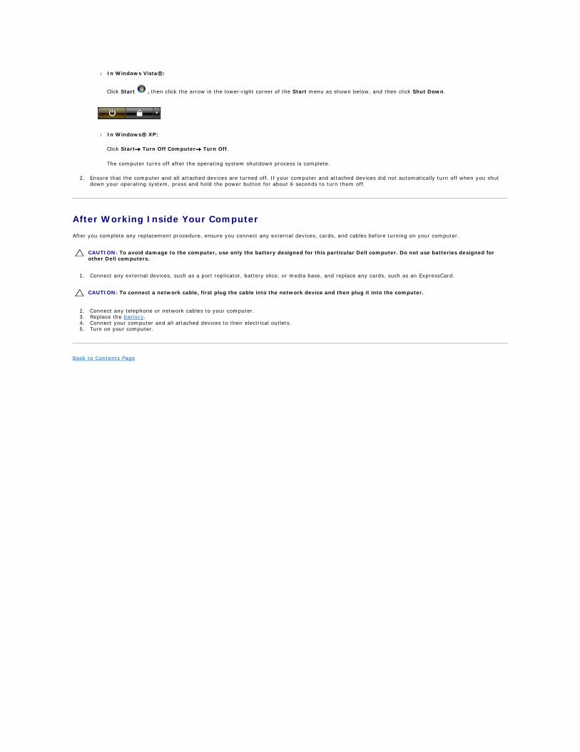
l In Windows Vista®:
Click Start , then click the arrow in the lower-right corner of the Start menu as shown below, and then click Shut Down.
l In Windows® XP:
Click Start® Turn Off Computer® Turn Off.
The computer turns off after the operating system shutdown process is complete.
2. Ensure that the computer and all attached devices are turned off. If your computer and attached devices did not automatically turn off when you shut down your operating system, press and hold the power button for about 6 seconds to turn them off.
After Working Inside Your Computer
After you complete any replacement procedure, ensure you connect any external devices, cards, and cables before turning on your computer.
1. Connect any external devices, such as a port replicator, battery slice, or media base, and replace any cards, such as an ExpressCard.
2. Connect any telephone or network cables to your computer. 3. Replace the battery. 4. Connect your computer and all attached devices to their electrical outlets. 5. Turn on your computer.
Back to Contents Page
CAUTION: To avoid damage to the computer, use only the battery designed for this particular Dell computer. Do not use batteries designed for other Dell computers.
CAUTION: To connect a network cable, first plug the cable into the network device and then plug it into the computer.