Embed Size (px)
Citation preview

Volume XXII 2019
ISSUE no.2
MBNA Publishing House Constanta 2019
doi: 10.21279/1454-864X-19-I2-027 SBNA© 2019. This work is licensed under the CC BY-NC-SA 4.0 License
SBNA PAPER • OPEN ACCESS
Influence of trim and rudder angle on ship handling
To cite this article: Alecu Toma, Alexandru Stefan Bacioiu, Iulian-Adrian Chirita, Scientific Bulletin of Naval Academy, Vol. XXII 2019, pg.228-233.
Available online at www.anmb.ro
ISSN: 2392-8956; ISSN-L: 1454-864X

INFLUENCE OF TRIM AND RUDDER ANGLE ON SHIP HANDLING
Alecu Toma1
Alexandru Stefan Bacioiu2
Iulian-Adrian Chirita3
1. Assistant Professor, Eng., PhD, „MirceacelBatran” Naval Academy, Constanta, Romania, [email protected] 2. MSc Student, Eng., „MirceacelBatran” Naval Academy, Constanta, Romania, [email protected] 3. Student, „MirceacelBatran” Naval Academy, Constanta, Romania
Abstract:The purpose of this paper is to identify the influence of trim and rudder angle on ship handling. Studying this matter using all available means, actual power rating at different trim values was put at comparison, also pressure diagrams and speed diagrams were taken into consideration. Upon completion of the paper, the actual power variation graph was plotted against the angle of trim. Keywords: ship handling, trim, rudder angle, ansys, autopower
INTRODUCTION The ANSYS program was designed to
be able to be used with an APDL parameter programming language (ANSYS Parametric Design Language). It allows the use of commands to generate the model in the program with finite elements in terms of some parameters (variables). Also, a number of results can be extracted through some parameters and used to get a number of functions required especially in the optimization module.
Almost all CFDs are based on the Navier-Stokes equations, derived from Newton's second law on fluid flow.
The exact numerical solution of the Navier-Stokes equations for turbulent flow is extremely demanding due to the wide range of time scales and dimensions involved in turbulent flow.
In order to simulate the process, the ANSYS-FLUENT program, which deals with the fluid flow study, was called for.
Consider the body of the ship floating in a parallelepiped body with a sea water density of 1025. In the next figure are presented the flow directions.
The body volume in water is 6085 m3 and the surface area of the 4750.4 m2, with 15 surfaces and 37 angles.
Figure 1.The constructive dimensions of the
body
Figure 2.Presentation of the analyzed model
In the above figure is presented the
body model of the ship made with the functions of the program.
PROFILE MESHING
At this stage, we have meshed the reservoir. The higher the number of cells, the more laborious the calculation of the parameters and it takes a longer time. We meshed the

model previously created using refining functions as in Figure 3.
Figure 3.The final meshed model.
The meshed structure has 61713 nodes
and 350327 components. PRESENTATION OF SIMULATION
RESULTS AT DIFFERENT SPEEDS Results pressures and speeds around
the hull for different angle of trim are given in the figures below.
Figure 4.Pressure diagram around the ship's
body at 0° trim
Figure 5.Speed diagram around the ship's body
at 0° trim
Figure 6.Pressure diagram around the ship's
body at 2° trim
Figure 7.Speed diagram around the ship's body
at 2° trim
Figure 8.Pressure diagram around the ship's
body at 4° trim

Figure 9.Speed diagram around the ship's body
at 4° trim
Figure 10.Pressure diagram around the ship's
body at 6° trim
Figure 11.Speed diagram around the ship's body
at 6° trim
Figure 12.Pressure diagram around the ship's
body at 8° trim
Figure 13.Speed diagram around the ship's body
at 8° trim
Figure 14.Pressure diagram around the ship's
body at 10° trim

Figure 15.Speed diagram around the ship's body
at 10° trim
Figure 16.Pressure diagram around the ship's
body at 12° trim
Figure 17.Speed diagram around the ship's body
at 12° trim
CENTRALIZING THE RESULTS
Figure 18.Presentation of variation of real ship resistance based on trim
Figure 19.Presentation of propulsion power variation according to trim INFLUENCE OF TRIM ON SHIP HANDLING
In order to make the calculation, the ship shall be deemed to have trim by the bow or by the stern at an angle of 0 to 5 °. Thus, with these values, the draft and the draft difference will be calculated by applying the formula:
��� =∆�
���/2
where: ΔT - the difference in draft between the aft and the bow. Lpp = 84.94 m length between ship's perpendicular.
This will result in the spreadsheet calculation table:
Table 1.Calculation values for drafts
� ��� ∆�[m] ���[m] ���[m]
0 0 0 5,68 5,68
1 0,01745 0,7413 6,4213 4,938
2 0,0349 1,483 7,163 4,197
3 0,0524 2,225 7,905 3,423
4 0,0699 2,969 8,649 2,711
5 0,0874 3,71 - -
The case of the vessel is similar to the inverted drafts. The case of 5 degrees of the angle of the cut leads to a value of the very large
0
500
1000
0.00 5.00 10.00
Re
sist
en
ce
[k
N]
Ship's trimin degrees
0
2000
4000
0.00 5.00 10.00
Po
we
r [k
W]
Trim of ship (degrees)
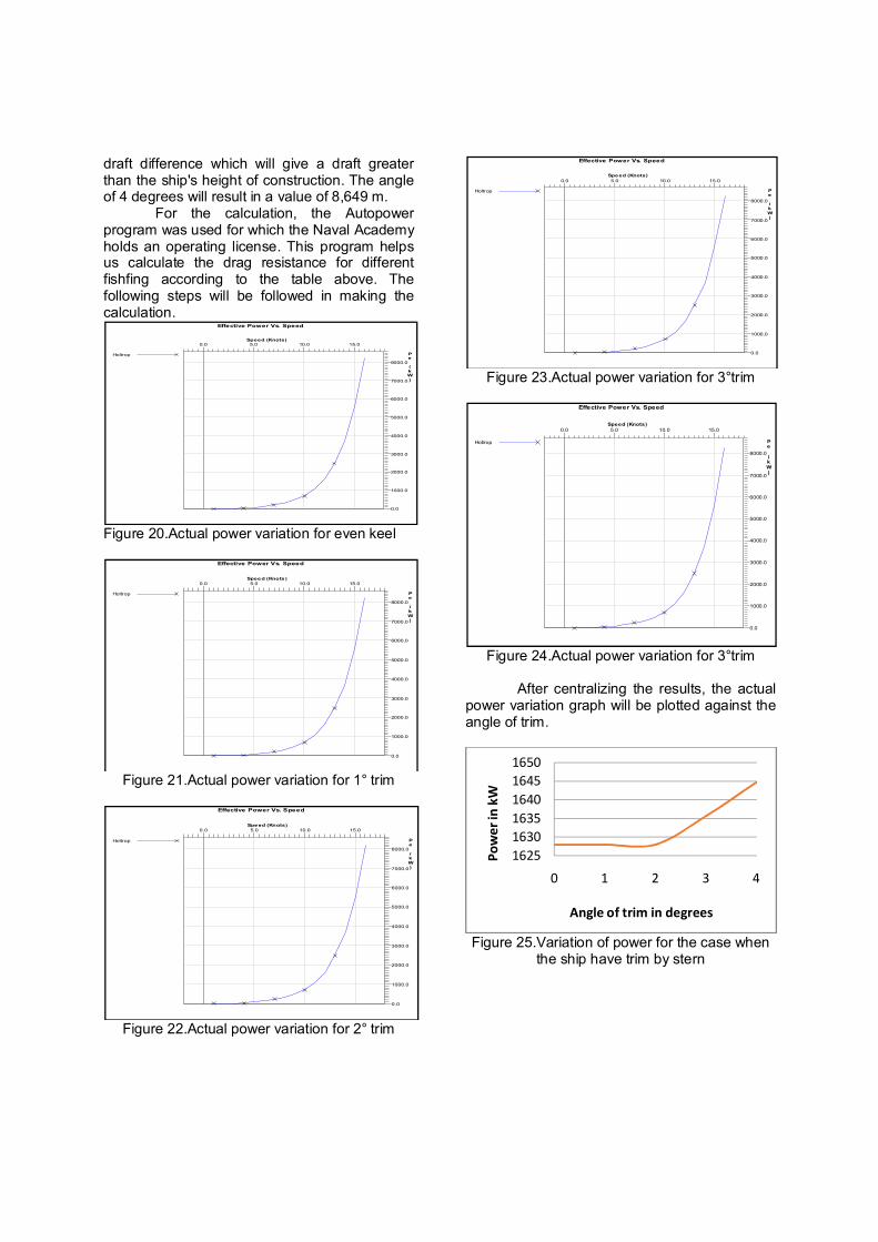
draft difference which will give a draft greater than the ship's height of construction. The angle of 4 degrees will result in a value of 8,649 m.
For the calculation, the Autopower program was used for which the Naval Academy holds an operating license. This program helps us calculate the drag resistance for different fishfing according to the table above. The following steps will be followed in making the calculation.
Figure 20.Actual power variation for even keel
Figure 21.Actual power variation for 1° trim
Figure 22.Actual power variation for 2° trim
Figure 23.Actual power variation for 3°trim
Figure 24.Actual power variation for 3°trim
After centralizing the results, the actual
power variation graph will be plotted against the angle of trim.
Figure 25.Variation of power for the case when
the ship have trim by stern
Effective Power Vs. Speed
Speed (Knots)
Pe (kW)
0.0 5.0 10.0 15.0
0.0
1000.0
2000.0
3000.0
4000.0
5000.0
6000.0
7000.0
8000.0
Holtrop
Effective Power Vs. Speed
Speed (Knots )
Pe (kW)
0.0 5.0 10.0 15.0
0.0
1000.0
2000.0
3000.0
4000.0
5000.0
6000.0
7000.0
8000.0
Holtrop
Effective Power Vs. Speed
Speed (Knots)
Pe (kW)
0.0 5.0 10.0 15.0
0.0
1000.0
2000.0
3000.0
4000.0
5000.0
6000.0
7000.0
8000.0
Holtrop
Effective Power Vs. Speed
Speed (Knots)
Pe (kW)
0.0 5.0 10.0 15.0
0.0
1000.0
2000.0
3000.0
4000.0
5000.0
6000.0
7000.0
8000.0
Holtrop
Effective Power Vs. Speed
Speed (Knots)
Pe (kW)
0.0 5.0 10.0 15.0
0.0
1000.0
2000.0
3000.0
4000.0
5000.0
6000.0
7000.0
8000.0
Holtrop
1625
1630
1635
1640
1645
1650
0 1 2 3 4
Po
we
r in
kW
Angle of trim in degrees

Figure 26.Variation of power for the case when
the ship have trim by head
Figure 27.Comparative presentation of the two
As can be seen only in the case of trimmed by stern ship, it can be considered a rule, the power
increases with increasing the power of the trim angle. The 5-degree angle values were not calculated due to the fact that the value of the draft exceeded significantly the value of the ship's construction width.
Bibliography: [1] C.B. Barrass, Captain D.R. Derret; Combined listed and trim; Vol. 20; 2006; pg. 98-201; [2] M. Ueno, Y. Yoshimura, Y. Tsukada, H. Miyazaki; Circular motion tests and uncertainty
analysis for ships maneuverability; Vol. 1; 2009; pg. 470-484; [3] S. Haik, S.D. Ross; Geometry of escaping dynamics in nonlinear ship motion; Vol 47; 2017; pg
48-70;
1627
1628
1629
1630
1631
1632
1633
0 1 2 3 4
Po
we
r in
kW
Angle of trim in degrees
1625
1630
1635
1640
1645
1650
0 1 2 3 4
Po
we
r in
kW
Angle of trim in degrees