Embed Size (px)
Citation preview
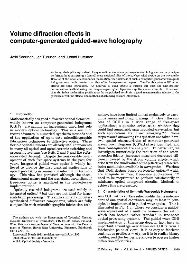
Volume diffraction effects incomputer-generated guided-wave holography
Jyrki Saarinen, Jari Turunen, and Juhani Huttunen
An integrated-optics equivalent of any one-dimensional computer-generated hologram can, in principle,be formed by a patterning a (scaled) cross-sectional slice of the surface relief profile on the waveguide.Because of the small effective-index modulation, the thickness of such a computer-generated waveguidehologram must be far greater than that of its free-space counterpart. Considerable volume diffractioneffects are thus introduced. An analysis of such effects is carried out with the thin-grating-decomposition method, using Fourier-plane-grating multiple beam splitters as an example. It is shownthat the index-modulation profile must be reoptimized to obtain a good reconstruction fidelity in thepresence of volume effects, and methods of achieving this are introduced.
1. Introduction
Mathematically designed diffractive optical elements,widely known as computer-generated holograms(CGH's), are gaining an increasingly important rolein modern optical technology. This is a result ofrecent advances in numerical synthesis methods andof the application of up-to-date microlithographicfabrication techniques to diffractive optics. Theseflexible optical elements are already vital componentsin many all-optical and optoelectronic switching andprocessing systems (see Refs. 2 and 3 and the refer-ences cited therein). Despite the considerable devel-opment of such free-space systems in the past fewyears, integrated guided-wave optics is widely be-lieved to provide the first practical applications ofoptical processing in commercial information technol-ogy. This view has persisted, although the three-dimensional nature and the associated parallelism offree-space optics is sacrificed in the guided-waveimplementation.
Optically recorded holograms are used widely inintegrated optics,46 but they are not ideal for large-scale batch processing. The applications of computer-synthesized diffractive components, which are fullycomparable with microlithographic fabrication tech-
The authors are with the Department of Technical Physics,Helsinki University of Technology, FIN-02150, Espoo, Finland.When this work was performed J. Turunen was with the Depart-ment of Physics, Heriot-Watt University, Riccarton, EdinburghEH14 4AS, UK.
Received 26 March 1993; revision received 2 July 1993.0003-6935/94/061035-09$06.00/0.© 1994 Optical Society of America.
nology, have been limited almost exclusively to wave-guide lenses and Bragg gratings.7 -9 Given the suc-cess of CGH's in a wide range of free-spaceapplications, a question arises as to whether theycould find comparable uses in guided-wave optics, butsuch applications are indeed emerging.1011 Somesteps toward answering this question are taken here:two special characteristics of computer-generatedwaveguide holograms (CGWH's) are identified, andtheir consequences are analyzed. In particular, weinvestigate numerically the reduction of the recon-struction fidelity (increased noise and decreased effi-ciency) caused by the strong volume effects, whicharise from the small values of the (effective) refractive-index modulation available in waveguides. We showthat CGH designs based on Fourier optics,12 whichare adequate in most free-space applications,3-15
need to be reoptimized to perform satisfactorily inminiature optical integrated circuits. Methods toachieve this are presented.
2. Characteristics of Synthetic Waveguide Holograms
Any CGH with a surface relief profile that is indepen-dent of one spatial coordinate may, at least in prin-ciple, be implemented in guided-wave optics. This isillustrated in Fig. 1(a), where we consider a guided-wave equivalent of a multiple beam-splitter setup,which has become rather standard in free-spaceoptical-processing systems. The guided-wave CGHimplementation of this setup does, in fact, have animportant advantage over free-space CGH's from afabrication point of view: it is as easy to fabricatecontinuous profiles z = h(y) as it is to realize binaryprofiles, and the former are known to possess higherdiffraction efficiencies.1
20 February 1994 / Vol. 33, No. 6 / APPLIED OPTICS 1035
(a) CGH
n wplane wave I
.i
(a)
CGWH + Fresnel lens
(b) O h z
guided dplane diffractdgie ln aewave I
Fig. 1. (a) Free-space computer-generated hologram (CGH) andan equivalent computer-generated waveguide hologram (CGWH)for 1/6 beam splitting. (b) Geometry and notation of a Fourier-plane CGWH.
The CGH illustrated in Fig. 1(a) is a grating with amathematically synthesized surface-relief profile de-signed to split the incident plane wave into an array ofX= 6 adjacent equal-intensity diffraction orders.These plane waves are focused into spots by a lens,which could be diffractive, as illustrated in the wave-guide implementation in Fig. 1(a). We have pro-moted this setup as an alternative to the moreconventional channel-waveguide beam splitters cur-rently used in integrated optics.1011 Because of theexistence of such an immediate application, thisparticular type of Fourier-plane CGWH is used as anexample throughout the paper. We have recentlydiscussed topics closely related to the subject matterof this paper, using diffractive waveguide lenses as anexample of Fresnel-region CGWH's.16 The character-istics of Fourier-plane and Fresnel-region elementsare, however, significantly different, requiring a sepa-rate analysis.
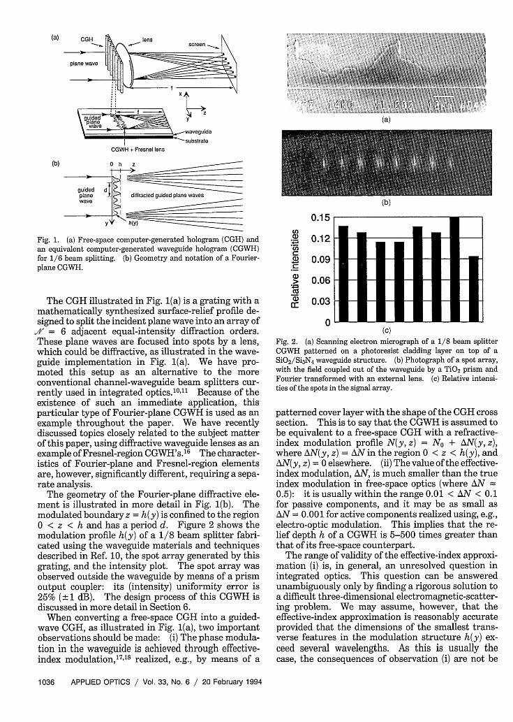
The geometry of the Fourier-plane diffractive ele-ment is illustrated in more detail in Fig. 1(b). Themodulated boundary z = h(y) is confined to the regiono < z < h and has a period d. Figure 2 shows themodulation profile h(y) of a 1/8 beam splitter fabri-cated using the waveguide materials and techniquesdescribed in Ref. 10, the spot array generated by thisgrating, and the intensity plot. The spot array wasobserved outside the waveguide by means of a prismoutput coupler: its (intensity) uniformity error is25% ( 1 dB). The design process of this CGWH isdiscussed in more detail in Section 6.
When converting a free-space CGH into a guided-wave CGH, as illustrated in Fig. 1(a), two importantobservations should be made: (i) The phase modula-tion in the waveguide is achieved through effective-index modulation, 1 7"18 realized, e.g., by means of a
(b)
A 1
a)
W
C
a)
v. z _
0.12
0.09
0.06
0.03
0(c)
Fig. 2. (a) Scanning electron micrograph of a 1/8 beam splitterCGWH patterned on a photoresist cladding layer on top of aSiO2/Si3N4 waveguide structure. (b) Photograph of a spot array,with the field coupled out of the waveguide by a TiO2 prism andFourier transformed with an external lens. (c) Relative intensi-ties of the spots in the signal array.
patterned cover layer with the shape of the CGH crosssection. This is to say that the CGWH is assumed tobe equivalent to a free-space CGH with a refractive-index modulation profile N(y, z) = No + AN(y, z),where AN(y, z) = AN in the region 0 < z < h(y), andAN(y, z) = 0 elsewhere. (ii) The value of the effective-index modulation, AN, is much smaller than the trueindex modulation in free-space optics (where AN 0.5): it is usually within the range 0.01 < AN < 0.1for passive components, and it may be as small asAN = 0.001 for active components realized using, e.g.,electro-optic modulation. This implies that the re-lief depth h of a CGWH is 5-500 times greater thanthat of its free-space counterpart.
The range of validity of the effective-index approxi-mation (i) is, in general, an unresolved question inintegrated optics. This question can be answeredunambiguously only by finding a rigorous solution toa difficult three-dimensional electromagnetic-scatter-ing problem. We may assume, however, that theeffective-index approximation is reasonably accurateprovided that the dimensions of the smallest trans-verse features in the modulation structure h(y) ex-ceed several wavelengths. As this is usually thecase, the consequences of observation (i) are not be
1036 APPLIED OPTICS / Vol. 33, No. 6 / 20 February 1994
lensscreo __
- - If
X T -
discussed further, and we treat the CGWH as if itwere a weakly modulated free-space CGH with a deepsurface-relief modulation profile. We note, however,that the fabrication accuracy of CGWH's is approach-ing the region where the validity of the effective-indexapproximation becomes questionable.
Our main concern in this paper is observation (ii).In addition to the fact that, for a given period d, themodulation depth, h, of the GGWH is 5-500 timesgreater than that of its free-space counterpart, dmust usually be smaller than in free-space optics,because the focal length f in Fig. 1(a) must be small inminiature optical integrated circuits. We are there-fore faced with a situation not unlike that encoun-tered several decades ago in acousto-optics (see Ref.19, Chap. 2): the thin-grating (or Raman-Nath)approximation is not valid. To predict the perfor-mance of a diffractive element, we must apply meth-ods that fully take into account volume effects in theintermediate region between the well-understood Ra-man-Nath and Bragg regimes. An essential differ-ence between acousto-optic and guided-wave diffrac-tive elements is the fact that acousto-optic gratings(and synthetic acousto-optic holograms20 ) are purelygradient-index elements, whereas guided-wave diffrac-tive elements are typically, though not exclusively,7
gradient-thickness elements, as illustrated in Fig. 1.
3. Algorithm
Assuming that the effective-index approximation isvalid, we should ideally solve the remaining two-dimensional diffraction problem by applying the nu-merical methods of rigorous electromagnetic gratingtheory2 1 (see Ref. 22 for a review of such methods).In guided-wave optics, however, these computation-ally intensive techniques are no longer rigorous:the effective-index approximation invalidates boththe field representations and the boundary conditions.Fortunately, the small values of AN imply that moreapproximate methods, which are computationallyless heavy, may be expected to give adequate results.We use a paraxial scalar algorithm, which we call thethin-grating-decomposition method (TGDM) mainlybecause we are concerned with periodic profiles z =h(y). Methods of this type have been used in variousareas of acoustics and optics for a long time (see, e.g.,Ref. 19, section 5.6, and Ref. 23). In fiber andintegrated optics they are usually known as beampropagation methods.2 >27 The idea is to divide themodulated structure into thin slabs and propagatethe field through each slab as if it were homogeneous;the effect of the true index variation inside the slab isaccounted for by assuming that an equivalent phasedelay may be inflicted on the wave front by a thingrating (thickness E -> 0) located at the exit boundaryof the slab. Our implementation of TGDM is summa-rized below.
The region 0 < z < h is divided into Q slabs(q - 1)h/Q < z < qh/Q, q = 1, . . , Q, of thicknessAz = h/Q. The coherent field [time dependenceexp(-iot)] is propagated through the modulated re-gion with the following stepwise algorithm, which is
repeated for each slab. In plane Zql = (q - 1)h/Q,the field U(y, zq-) is expanded in the form of itsangular spectrum.28 Because of the periodicity ofh(y), the angular spectrum is a superposition ofdiscrete plane-wave components with amplitudes
1 rdAm(zqi,) = d f U(y, zq )exp(-i2Trmy/d)dy, (1)
where m = integer. The angular spectrum {Aml ispropagated into the plane zq- = qh/Q - E, assumingthat the refractive index inside the slab is No: inparaxial approximation, we have
Am(zq-) = Am(zq-i)exp[-irX(m/d)2Az] (2)
where X = X0 /N0 and Xo represents the wavelength oflight in vacuum. The field in plane Zq- is then
U(y, Zq-) = A(zq-)exp(i2Trmy/d).m= -x
(3)
The effect of the actual grating structure inside theslab is accounted for by a multiplicative phase-correction term
U(y, Zq) = U(y, zq-)exp[i(2T/XO)AzAN(y, qh/Q)], (4)
where AzAN(y, qh/Q) represents an approximationto the perturbation of the optical path length, calcu-lated along the liney = constant through the qth slab.
In practice, we compute Am(zqi-) and U(y, zq-) bythe fast Fourier transform algorithm, taking an evennumber M of equally spaced samples of U(y, zq- 1) andretaining plane-wave components m = -M/2 + 1,... , M/2 in Eq. (3). The parameters affecting thecomputational cost are then M and Q. It was ob-served that Q = 100 slabs suffice regardless of thevalue of AN and that M = 8192 sampling points wereadequate in all calculations, in the sense that nofurther increase of Q or M changed the resultssignificantly.
4. Predesign by Fourier Optics
The beam-splitter gratings to be analyzed below weredesigned using the thin-grating approximation, i.e.,assuming that the amplitudes of the diffraction or-ders are given by
Am(h) = - U(y, h)exp(-i2rmy/d)dy,
where
U(y, h) = U(y, 0)exp[iCF(y)]
= U(y, o)exp i(2T/Xo) AN(y z)dzl,
(5)
(6)
and assuming a normally incident unit-amplitudeplane wave, U(y, 0) = 1. The fidelity of the beam-
20 February 1994 / Vol. 33, No. 6 / APPLIED OPTICS 1037

splitter element is characterized throughout thispaper by two figures of merit, the diffraction effi-ciency,
,I = E IAm(h)12 = E q.,mEW MEW
(7)
(a) 27cr
e
0and the uniformity error (or reconstruction error),
AR = aXl qn 111/;1, (8)
where qm represent the efficiencies of individualdiffraction orders. In Eqs. (7) and (8), the signalwindow, W, is chosen to contain an even numberXofdiffraction orders: m = -///2 + ...... , /2.
Two different methods were used to encode theprofile z = h(y). We first assumed a cellular profileof the form
h(y) = h, = 2X NDI,
(I - )d/L < y < Id/L,
The parameters (I were optimized using the methodof Ref. 29. Second, we assumed a profile of the form
h(y) = ho + 2'rAN' 7ry/d + cp cos(2ITPy/d)J[ p s27p
x 22-rrAN
(10)
where ho is a constant chosen such that h(y) 2 0 for0 < y < d, and the parameters cp, p = 1,..., P areused as the optimization variables. Because qm =91-m for this profile, only orders m = 1, . . ., X/2need to be considered. The parametric optimizationis performed using a downhill algorithm, evaluating{flm} by fast Fourier transform. This method is notparticularly efficient, but it is adequate for one-dimensional signals.
It is of practical interest to consider solutions with. = 2n beams, where n = integer. Using the codingmethod of Eq. (9) with L = 50 cells, we obtained -q =91.8%, 95.4%, and 94.0% for X = 4, 8, and 16,respectively. For all solutions, AR < 0.5%. Essen-tially similar results were obtained by the secondcoding scheme of Eq. (10). For example, an eight-beam solution with q = 95.4% and AR = 0.2% wasfound with just four variables, c = 1.9482, 2 =
0.7745, C3 = -0.4516, and C4 = 0.1675. These fourprofiles are illustrated in Fig. 3. It is interesting tocompare the eight-beam solutions in Figs. 3(b) and3(d). The profile in Fig. 3(b) is a close approximationof the profile Fig. 3(d), except that it is reversed bothvertically and horizontally. Within the (paraxial)thin-grating approximation, there are four reversedsolutions, which are functionally equivalent. Thisequivalence also holds, to a good approximation, inthe presence of volume diffraction effects, which wenow proceed to consider.
(b) 2it
0
(c) 4n
E 2t
0
(d) 2t
ILe
0
�mTflTflh1h�
0
AdVd
y
0 dy
0 dy
0 Y d
Fig. 3. Phase profiles CF(y) of cellular solutions with (a) .4/ = 4, (b)I = 8, and (c) .V = 16, and (d) a continuous solution with ./ = 8.
5. Analysis of Fourier-Optics Designs
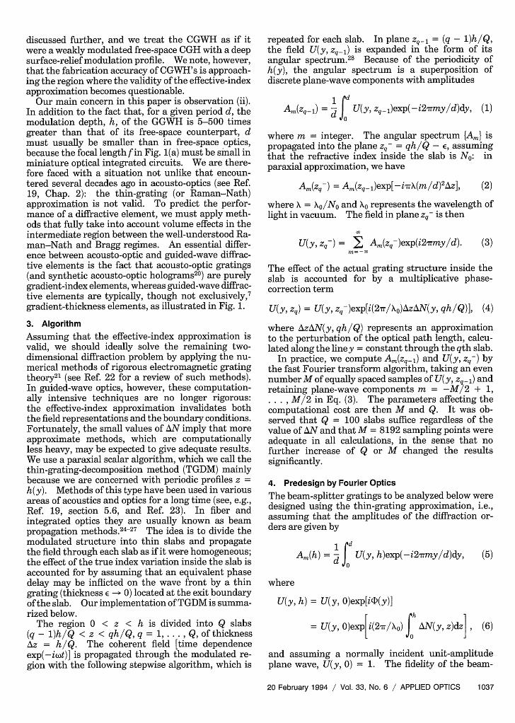
The main purpose of this section is to analyze, usingTGDM, the validity of the Fourier-optics gratingdesigns given above, in the presence of the volumeeffects encountered in guided-wave optics. Beforeembarking on this task, we establish the adequacy ofTGDM by comparing it with the electromagneticapproach used in Ref. 14. We consider the four-beam solution of Fig. 3(a) and evaluate the efficiencies,]m of orders m = -1, . . ., 2 as a function of thegrating period, d, normalized to the wavelength X =\ 0 /N0 of the guided wave. The results for AN = 0.1and AN = 0.01 are shown in Figs. 4(a) and 4(b),respectively. The dashed horizontal lines in Figs. 4denote the predictions of Fourier optics; i.e., theefficiencies are equal and independent of d. ForAN < 0.1, excellent agreement is observed betweenthe predictions of TGDM and the electromagneticapproach if d/X > 20 (deviations are less than 1%when d/X < 20). For AN = 0.01, the results arevirtually indistinguishable for all values of d. Thisresult demonstrates that TGDM is valid in the analy-sis of Fourier-optics designs, and it also shows that
1038 APPLIED OPTICS / Vol. 33, No. 6 / 20 February 1994
1 t:1:1 .g:1: t :1 l 1:t t :1:W 1 :I.t:1 �5cg.l. t I:l::1::1:1.1:t:I:.t:I::lot::l::ti1:I't::g::R:3
(9)
(a) 40
30
E
20
100
(b) 100
80
E60
40
20
0
20 40 60d/k
(a) 5'
4'
'3:
80 100
3
2'
00.1
0 L...... 0.05
.... -00050o \ A------ 0.0010~~~~~ 0.0010 -
nu~~~. ).
0
(b) 50
40
E 30
, 20
10
0
(c) 50
0 4 8 12 16 20
Fig. 4. Diffraction efficiencies qim of various orders for the elementconsidered in Fig. 3(a) as a function of the grating period d/X withthe modulation (a) AN = 0.1 and (b) AN = 0.01 calculated by thethin-grating-decomposition method (TGDM), the electromagneticapproach used in Ref. 14, and Fourier optics.
TGDM is reliable deep inside the region where theFourier-optics solutions are inadequate. In otherwords, no significant error is made by converting theboundary-value (scattering) problem into an initialvalue problem. We emphasize, however, that thiscomparison is based on the effective-index approxima-tion, and thus the electromagnetic approach does notpredict the boundary effects precisely (e.g., it does notinclude the waveguide radiation modes).
We note in passing that, although the thin gratingswere assumed to be equally spaced in the formulationof Section 3, this assumption is unnecessary. Norestrictions were placed on the values of (I in theFourier-optics design, and in the TGDM analysis weused unequal step spacings Az < h/100 to ensurethat TGDM does not introduce quantization of (D.
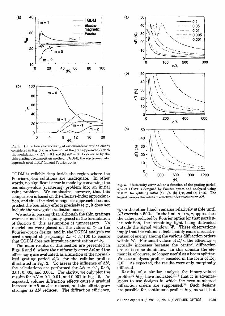
The main results of this section are presented inFigs. 5 and 6, where the uniformity error AR and theefficiency ' are evaluated, as a function of the normal-ized grating period d/X, for the cellular profilesillustrated in Fig. 3. To assess the influence of AN,the calculations are performed for AN = 0.1, 0.05,0.01, 0.005, and 0.001. For clarity, we only plot theresults for AN = 0.1, 0.01, and 0.001 in Figs. 6. Asexpected, volume diffraction effects cause a gradualincrease in AR as d is reduced, and the effects growstronger as AN reduces. The diffraction efficiency,
40
30
20
10
0
100 200 300
0 200 400 60d/%
0
0 300 600 900 1200d/X
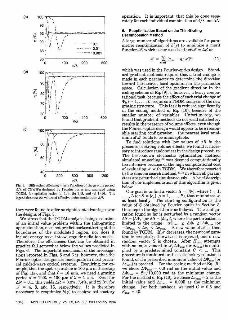
Fig. 5. Uniformity error AR as a function of the grating periodd/X of CGWH's designed by Fourier optics and analyzed usingTGDM, for splitting ratios (a) 1/4, (b) 1/8, and (c) 1/16. Thelegend denotes the values of effective-index modulation AN.
Aq, on the other hand, remains relatively stable untilAR exceeds 50%. In the limit d -- c, N-j approachesthe value predicted by Fourier optics for that particu-lar solution, the remaining light being diffractedoutside the signal window, W. These observationsimply that the volume effects mainly cause a redistri-bution of energy among the various diffraction orderswithin W. For small values of d/X, the efficiency Xactually increases because the central diffractionorders become dominant. In this domain the ele-ment is, of course, no longer useful as a beam splitter.We also analyzed profiles encoded in the form of Eq.(10). As expected, the results were only marginallydifferent.
Results of a similar analysis for binary-valuedprofiles30 h(y) have indicated10'11 that it is advanta-geous to use designs in which the even-numbereddiffraction orders are suppressed.3 1 Such designsare possible for continuous profiles h(y) as well, but
20 February 1994 / Vol. 33, No. 6 / APPLIED OPTICS 1039
.k~~~1. \ I "I
._
I\ ~ ~ '\. I.\ \"I
- 1. "I "I~
1
(a) 100
96
;: 92
$~ 90
88
86
(b) 100
0
90
80
70
60
(C) 100
0
0 100 .__ 200 300
I I /
Ii III I I
I/ I /
I,~~~~~~~~~~~~~~~~~~~~~~~
0 200 400 60(d/%
I t-
/ I-
80 1 1"
jI
60 I! I\//60 I \
AnMUv0 300 600 900 1200
d/XFig. 6. Diffraction efficiency Xq as a function of the grating periodd/X of CGWH's designed by Fourier optics and analyzed usingTGDM, for splitting ratios (a) 1/4, (b) 1/8, and (c) 1/16. Thelegend denotes the values of effective-index modulation AN.
they were found to offer no significant advantage overthe designs of Figs. 3.
We stress that the TGDM analysis, being a solutionof an initial value problem within the thin-gratingapproximation, does not predict backscattering at theboundaries of the modulated region, nor does itinclude energy losses into waveguide radiation modes.Therefore, the efficiencies that can be obtained inpractice fall somewhat below the values predicted inFigs. 6. The important conclusion of the investiga-tions reported in Figs. 5 and 6 is, however, that theFourier-optics designs are inadequate in most practi-cal guided-wave optical systems. Requiring, for ex-ample, that the spot separation is 100 I~m in the setupof Fig. 1(a), and that f = 10 mm, we need a gratingperiod d = 10OX = 100 [lm if X = 1 plm. Even forAN = 0.1, this yields AR = 3.3%, 7.4%, and 22.3% for.1 = 4, 8, and 16, espectively. It is thereforenecessary to reoptimize h(y) to achieve satisfactory
operation. It is important, that this be done sepa-rately for each individual combination of d/X and AN.
6. Reoptimization Based on the Thin-GratingDecomposition Method
A large number of algorithms are available for para-metric reoptimization of h(y) to minimize a meritfunction ,A, which is our case is either X = AR or
= E (Tim - Ti/X)2 ' (11)mEW
which was used in the Fourier-optics design. Stand-ard gradient methods require that a trial change ismade in each parameter to determine the directiontoward the nearest local optimum in the parameterspace. Calculation of the gradient direction in thecoding scheme of Eq. (9) is, however, a heavy compu-tational task, because the effect of each trial change of'Di, I = 1, . . . , L, requires a TGDM analysis of the newgrating structure. This task is reduced significantlyin the coding method of Eq. (10), because of thesmaller number of variables. Unfortunately, wefound that gradient methods do not yield satisfactoryresults in the presence of volume effects, even thoughthe Fourier-optics design would appear to be a reason-able starting configuration: the nearest local mini-mum of.' tends to be unacceptable.
To find solutions with low values of AR in thepresence of strong volume effects, we found it neces-sary to introduce randomness in the design procedure.The best-known stochastic optimization method,simulated annealing,3 2 was deemed computationallytoo intensive because of the high computational costof evaluating' with TGDM. We therefore resortedto the random search method,33'34 in which all param-eters are perturbed simultaneously. A brief descrip-tion of our implementation of this algorithm is givenbelow.
Our goal is to find a vector S = {}, where I = 1,... , L (or S = {cp }, p = 1, . . . , P), that minimizesXat least locally. The starting configuration is thevalue of S obtained by Fourier optics in Section 3.One step in the algorithm is as follows: The configu-ration found so far is perturbed by a random vectorAS = {&L@I I (or AS = {Acp 1), where the perturbation islimited to the range - A(maC AI) < A(Fmax (or-Acm,, < cp < •Acma,,). A new value of ' is thenfound by TGDM. If.' decreases, the new configura-tion is accepted; otherwise it is rejected, and a newrandom vector S is chosen. After Kmax, attemptswith no improvement in .', A'Fma (or Ama,,) is multi-plied by a predetermined constant C < 1. Thisprocedure is continued until a satisfactory solution isfound, or if a prescribed minimum value of A(D\C[max (orAcmax) is reached. For the coding method of Eq. (9),we chose A"Dmx, = 0.6 rad as the initial value andA(Dmax = 2/10,000 rad as the minimum change.For the method of Eq. (10), we chose Acm,X = 2 as theinitial value and Acm, = 0.005 as the minimumchange. For both methods, we used C = 0.5 andKma = 40.
1040 APPLIED OPTICS / Vol. 33, No. 6 / 20 February 1994
I
I -/*1 I /
W a. \ / 0.1
----- 0.01l ~~~~~~0.001
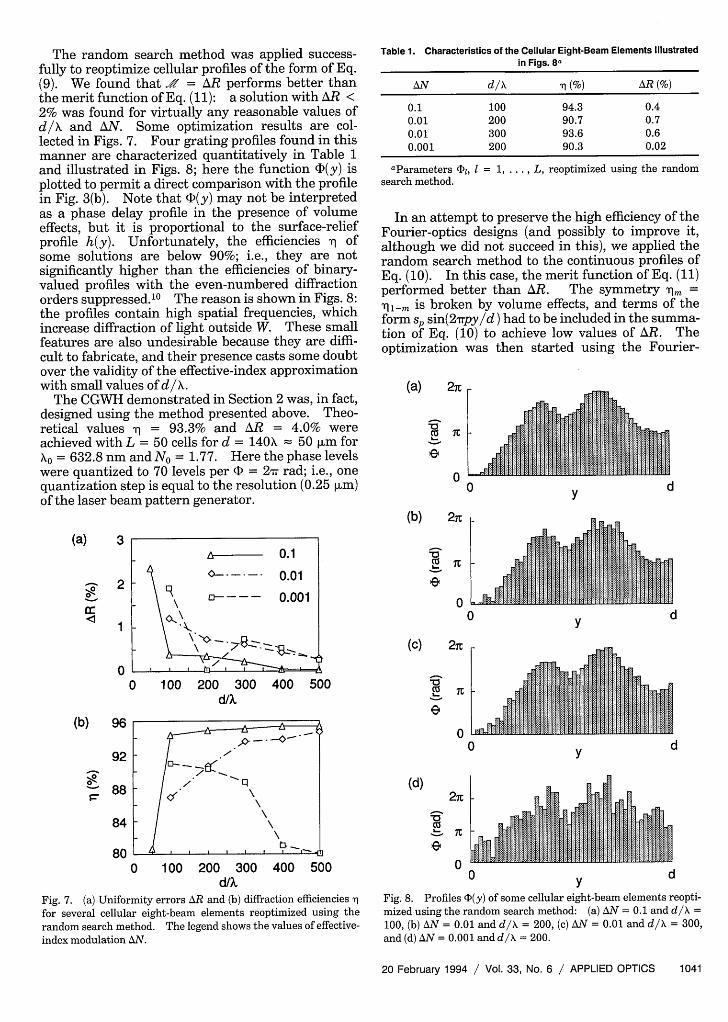
The random search method was applied success-fully to reoptimize cellular profiles of the form of Eq.(9). We found that = AR performs better thanthe merit function of Eq. (11): a solution with AR <2% was found for virtually any reasonable values ofd/X and AN. Some optimization results are col-lected in Figs. 7. Four grating profiles found in thismanner are characterized quantitatively in Table 1and illustrated in Figs. 8; here the function C(y) isplotted to permit a direct comparison with the profilein Fig. 3(b). Note that cl(y) may not be interpretedas a phase delay profile in the presence of volumeeffects, but it is proportional to the surface-reliefprofile h(y). Unfortunately, the efficiencies T ofsome solutions are below 90%; i.e., they are notsignificantly higher than the efficiencies of binary-valued profiles with the even-numbered diffractionorders suppressed. 10 The reason is shown in Figs. 8:the profiles contain high spatial frequencies, whichincrease diffraction of light outside W. These smallfeatures are also undesirable because they are diffi-cult to fabricate, and their presence casts some doubtover the validity of the effective-index approximationwith small values of d/X.
The CGWH demonstrated in Section 2 was, in fact,designed using the method presented above. Theo-retical values T = 93.3% and AR = 4.0% wereachieved with L = 50 cells for d = 140X = 50 Im foro= 632.8 nm and No = 1.77. Here the phase levels
were quantized to 70 levels per (D = 2 7r rad; i.e., onequantization step is equal to the resolution (0.25 pm)of the laser beam pattern generator.
(a) 3
0
a:
2
1
Table 1. Characteristics of the Cellular Eight-Beam Elements Illustratedin Figs. 8a
AN d/X (%) AR(%)
0.1 100 94.3 0.40.01 200 90.7 0.70.01 300 93.6 0.60.001 200 90.3 0.02
aParameters Fl, = 1, . L, reoptimized using the randomsearch method.
In an attempt to preserve the high efficiency of theFourier-optics designs (and possibly to improve it,although we did not succeed in this), we applied therandom search method to the continuous profiles ofEq. (10). In this case, the merit function of Eq. (11)performed better than AR. The symmetry Tim =Ti-rn is broken by volume effects, and terms of theform sp sin(2Trpy/d) had to be included in the summa-tion of Eq. (10) to achieve low values of AR. Theoptimization was then started using the Fourier-
(a) 27t
IC
e
00 y
(b) 2n
e
0
(C) 2nt
0
d
Y d
0
(b) 96
92
a088
84
80
0 100 200 300d/k
400 500
I 4 . . . I . I t |0 100 200 300 400 500
d/kFig. 7. (a) Uniformity errors AR and (b) diffraction efficiencies 1
for several cellular eight-beam elements reoptimized using therandom search method. The legend shows the values of effective-index modulation AN.
0
(d)
7t
0
0 dy
0 d
Fig. 8. Profiles <)(y) of some cellular eight-beam elements reopti-mized using the random search method: (a) AN = 0.1 and d/X =100, (b) AN = 0.01 and d/X = 200, (c) AN = 0.01 and d/X = 300,and (d) AN = 0.001 and d/X = 200.
20 February 1994 / Vol. 33, No. 6 / APPLIED OPTICS 1041
8

Table 2. Characteristics of the Continuous Eight-Beam ElementsIllustrated in Figs. 9a
AN d/X P (%) AR(%)
0.1 100 4 95.4 2.70.01 100 4 94.4 3.70.001 200 20 88.2 0.80.001 300 5 90.8 1.3
aParameters cp and sp, p = 1, P, reoptimized using therandom search method.
optics values for cp and sp=0forp=1,...,P. Goodresults were obtained in this manner: the perfor-mances of some of the eight-beam solutions are givenin Table 2, and their profiles are plotted in Figs. 9.In the presence of strong volume effects, low values ofAR could only be obtained by introducing extra,higher-order Fourier coefficients in h(y), as illus-trated in Fig. 9(c). This reduced the efficiency, whichconfirms the tendency seen in the case of cellularprofiles.
(a) 2ic
IC
e
00
(b)
v
IC
0
(C)
eIC
0
(d) 2it
IC
W00
dy
0 dy
0
n
dy
vi y Li
Fig. 9. Profiles (D(y) of some continuous eight-beam elementsreoptimized using the random search method: (a) AN = 0.1 andd/X = 100, (b) AN = 0.01 and d/X = 100, (c) AN = 0.001 and d/X =200, and (d) AN = 0.001 and d/X = 300.
There is no guarantee that the profiles found by themethods presented above are optima. These meth-ods often stagnate into an unacceptable local opti-mum, and the algorithm may have to be run severaltimes. Perhaps more significantly, there is no singlecriterion for the optimum solution: features to beconsidered are the efficiency, , the uniformity error,AR, and the complexity of the profile, and thesefeatures in general place contradictory demands onthe optimization process. This is, in particular, thecase when d/X and AN are small. Significant im-provements in performance may then be achieved,and the profiles may bear no resemblance to thestarting configuration. Similar behavior was ob-served in Ref. 16, where we applied methods of thistype to optimize the performance of high-numerical-aperture diffractive waveguide lenses.
7. Conclusions
We have investigated numerically the feasibility ofrealizing, in guided-wave optics, certain syntheticFourier-plane diffractive elements, which are well-established in free-space optics. It was demon-strated by means of the thin-grating-decompositionmethod (TGDM) that volume diffraction effects invali-date the Fourier-optics designs, which are usuallyadequate in free-space optics. It was also shownthat, by parametric reoptimization of the gratingprofile, it is possible to design elements that performwell in the presence of strong volume effects.
To keep the analysis concise and focused, we haveconsidered only one clearly defined application ofsynthetic Fourier-plane diffractive elements in guided-wave optics, i.e., multiple beam splitters. It seemsinevitable, considering the success of diffractive ele-ments in free-space optics, that other applications ofCGWH's with equal or greater practical value willemerge in areas such as wavelength multiplexing-demultiplexing, or active switching. We believe thatthe methods introduced here will prove useful in theanalysis and assessment of diffractive waveguideelements in such novel applications.
We thank E. Noponen for performing the electro-magnetic diffraction analysis, A. Salin of TerapixelInc. for providing the amplitude mask for the demon-stration, R. Suominen for providing the scanningelectron micrograph, and A. Vasara for his contribu-tions in the early stages of this work. The Jenny andAntti Wihuri Foundation, the Academy of Finland,and the Science and Engineering Research Council(UK) are acknowledged for financial support.
References1. F. Wyrowski and 0. Bryngdahl, "Digital holography as part of
diffractive optics," Rep. Prog. Phys. 54, 1481-1571 (1991).2. M. E. Prise, N. C. Craft, R. E. LaMarche, M. M. Downs, S. J.
Walker, L. A. D'Asaro, and L. M. F. Chirovsky, "Module foroptical logic circuits using symmetric self-electrooptic effectdevices," Appl. Opt. 29, 2164-2170 (1990).
3. F. B. McCormick, F. A. P. Tooley, J. L. Brubaker, J. M. Sasian,Y. J. Cloonan, A. L. Lentine, R. L. Morrison, R. J. Crisci, S. L.Walker, S. J. Hinterlong, and M. J. Herron, "Design and
1042 APPLIED OPTICS / Vol. 33, No. 6 / 20 February 1994
A

tolerancing comparisons for S-SEED-based free-space switch-ing fabrics," Opt. Eng. 31,2697-2711 (1992).
4. T. Suhara, H. Nishihara, and J. Koyama, "Waveguide holo-grams: a new approach to hologram interaction," Opt. Com-mun. 19, 353-358 (1976).
5. F. Lin, E. M. Strzelecki, C. Nguyen, and T. Jannson, "Highlyparallel single-mode multiplanar holographic interconnects,"Opt. Lett. 16, 183-185 (1991).
6. D. J. Brady and D. Psaltis, "Holographic interconnections inphotorefractive waveguides," Appl. Opt. 30,2324-2333 (1991).
7. T. Suhara and H. Nishihara, "Integrated optics componentsand devices using periodic structures," IEEE J. QuantumElectron. QE-22, 845-867 (1986).
8. H. Nishihara and T. Suhara, "Micro Fresnel lenses," inProgress in Optics, E. Wolf, ed. (North-Holland, Amsterdam,1987), Vol. 24, pp. 1-37.
9. H. Nishihara, M. Haruna, and T. Suhara, Optical IntegratedCircuits (McGraw-Hill, New York, 1989).
10. J. Saarinen, J. Huttunen, A. Vasara, E. Noponen, J. Turunen,and A. Salin, "Synthetic holographic beamsplitters for inte-grated optics," in Computer and Optically Generated Holo-graphic Optics, I. Cindrich and S. H. Lee, eds., Proc. Soc.Photo-Opt. Instrum. Eng. 1555, 128-137 (1991).
11. J. Saarinen, J. Huttunen, A. Vasara, and J. Turunen, "Com-puter-generated guided-wave holography: application to beamsplitting," Opt. Lett. 17, 300-302 (1992).
12. J. W. Goodman, Introduction to Fourier Optics (McGraw-Hill,New York, 1968).
13. A. Vasara, E. Noponen, J. Turunen, J. M. Miller, and M. R.
Taghizadeh, "Rigorous diffraction analysis of Dammann grat-ings," Opt. Commun. 81,337-342 (1991).
14. A. Vasara, M. R. Taghizadeh, J. Turunen, J. Westerholm, E.Noponen, H. Ichikawa, J. M. Miller, T. Jaakkola, and S.
Kuisma, "Binary surface-relief gratings for array illuminationin digital optics," Appl. Opt. 31, 3320-3336 (1992).
15. E. Noponen, J. Turunen, and A. Vasara, "Electromagnetictheory and design of diffractive lens arrays," J. Opt. Soc. Am. A10, 434-443 (1993).
16. J. Huttunen, J. Turunen, and J. Saarinen, "High-efficiencydiffractive waveguide lenses by parametric optimization,"Appl. Opt. (to be published).
17. V. Ramaswamy, "Strip-loaded film waveguide," Bell Syst.Tech. J. 53, 697-704 (1974).
18. Y-F. Li and J. W. Y. Lit, "General formulas for the guiding
properties of a multilayer slab waveguide," J. Opt. Soc. Am. A
4, 671-677 (1987).19. A. Korpel, Acousto-optics (Dekker, New York, 1988).
20. J. Turunen, E. Tervonen, and A. T. Friberg, "Acousto-opticcontrol and modulation of optical coherence by electronicallysynthesized holographic gratings," J. Appl. Phys. 67, 49-59(1990).
21. J-M. P. Delavaux, W. S. C. Chang, and M. G. Moharam,"Comparison of the experimental and theoretical diffractioncharacteristics of transmission gratings on planar dielectricwaveguides," Appl. Opt. 24, 221-226 (1985).
22. R. Petit, ed., Electromagnetic Theory of Gratings (Springer-Verlag, Berlin, 1980).
23. R. Alferness, "Analysis of optical propagation in thick holo-graphic gratings," Appl. Phys. 7, 29-33 (1975).
24. M. D. Feit and J. A. Fleck, "Light propagation in graded-indexoptical fibers," Appl. Opt. 17, 3990-3998 (1978).
25. J. Van Roey, J. van der Donk, and P. E. Lagasse, "Beam-
propagation method: analysis and assessment," J. Opt. Soc.Am. 71, 803-810 (1981).
26. L. Thyl6n, "The beam propagation method: an analysis of itsapplicability," Opt. Quantum Electron. 15,433-439 (1983).
27. P. E. Lagasse and R. Baets, "Application of propagating beam
methods to electromagnetic and acoustic wave propagationproblems: a review," Radio Sci.22, 1225-1233 (1987).
28. G. C. Sherman, "Introduction to the angular-spectrum repre-sentation of optical fields," in Applications of Mathematics inModern Optics, W. H. Carter, ed., Proc. Soc. Photo-Opt.Instrum. Eng. 358, 31-38 (1982).
29. J. Turunen, A. Vasara, and J. Westerholm, "Kinoform phaserelief synthesis: a stochastic method," Opt. Eng. 28, 1162-1167 (1989).
30. H. Dammann and K. G6rtler, "High-efficiency in-line multipleimaging by means of multiple phase holograms," Opt. Com-mun. 3, 312-315 (1971).
31. R. L. Morrison, "Symmetries that simplify the design of spotarray phase gratings," J. Opt. Soc. Am. A 9, 464-471 (1992).
32. S. Kirkpatrick, C. D. Gelatt, and M. P. Vecchi, "Optimization
by simulated annealing," Science 220, 671-680 (1983).33. R. L. Anderson, "Recent advances in finding best operating
conditions," J. Am. Statist. Assoc. 48, 789-798 (1953).34. F. J. Solis and R. J. E. Wets, "Minimization by random search
method," Math. Oper. Res. 6, 19-30 (1981).
20 February 1994 / Vol. 33, No. 6 / APPLIED OPTICS 1043