Embed Size (px)
Citation preview
Volume Bragg Grating for Coupling the Stokes
Wave Out of an Amplifier
by John E. McElhenny, Jeffrey O. White, Steven D. Rogers, and Tigran Sanamyan
ARL-TN-0409 September 2010 Approved for public release; distribution unlimited.
NOTICES
Disclaimers The findings in this report are not to be construed as an official Department of the Army position unless so designated by other authorized documents. Citation of manufacturer’s or trade names does not constitute an official endorsement or approval of the use thereof. Destroy this report when it is no longer needed. Do not return it to the originator.
Army Research Laboratory Adelphi, MD 20783-1197
ARL-TN-0409 September 2010
Volume Bragg Grating for Coupling the Stokes Wave Out of an Amplifier
John E. McElhenny, Jeffrey O. White,
Steven D. Rogers, and Tigran Sanamyan Sensors and Electron Devices Directorate, ARL
Approved for public release; distribution unlimited.
ii
REPORT DOCUMENTATION PAGE Form Approved OMB No. 0704-0188
Public reporting burden for this collection of information is estimated to average 1 hour per response, including the time for reviewing instructions, searching existing data sources, gathering and maintaining the data needed, and completing and reviewing the collection information. Send comments regarding this burden estimate or any other aspect of this collection of information, including suggestions for reducing the burden, to Department of Defense, Washington Headquarters Services, Directorate for Information Operations and Reports (0704-0188), 1215 Jefferson Davis Highway, Suite 1204, Arlington, VA 22202-4302. Respondents should be aware that notwithstanding any other provision of law, no person shall be subject to any penalty for failing to comply with a collection of information if it does not display a currently valid OMB control number. PLEASE DO NOT RETURN YOUR FORM TO THE ABOVE ADDRESS.
1. REPORT DATE (DD-MM-YYYY)
September 2010 2. REPORT TYPE
Final 3. DATES COVERED (From - To)
April to August 2010 4. TITLE AND SUBTITLE
Volume Bragg Grating for Coupling the Stokes Wave Out of an Amplifier 5a. CONTRACT NUMBER
5b. GRANT NUMBER
5c. PROGRAM ELEMENT NUMBER
6. AUTHOR(S)
John E. McElhenny, Jeffrey O. White, Steven D. Rogers, and Tigran Sanamyan 5d. PROJECT NUMBER
5e. TASK NUMBER
5f. WORK UNIT NUMBER
7. PERFORMING ORGANIZATION NAME(S) AND ADDRESS(ES)
U.S. Army Research Laboratory ATTN: RDRL-SEE-O 2800 Powder Mill Road Adelphi, MD 20783-1197
8. PERFORMING ORGANIZATION REPORT NUMBER
ARL-TN-0409
9. SPONSORING/MONITORING AGENCY NAME(S) AND ADDRESS(ES)
High Energy Laser Joint Technology Office (GEK0JTO) 791 University Blvd SE Ste 209 Albuquerque, NM 87106
10. SPONSOR/MONITOR’S ACRONYM(S) 11. SPONSOR/MONITOR'S REPORT NUMBER(S)
12. DISTRIBUTION/AVAILABILITY STATEMENT
Approved for public release; distribution unlimited
13. SUPPLEMENTARY NOTES
14. ABSTRACT
High power multimode fiber (MMF) master-oscillator power amplifiers (MOPAs) with stimulated Brillouin scattering (SBS) beam cleanup and wavefront reversal are under development at the U.S. Army Research Laboratory (ARL) to counter rockets, artillery, and mortar (CRAM). When Faraday isolators are used for outcoupling the Stokes light in the MMF MOPAs, the power scalability is limited. Volume Bragg gratings (VBGs) appear to be more scalable. We report here the results of tests on a VBG designed to separate wavelengths 0.0604 nm (16 GHz) apart, corresponding to the SBS frequency shift at 1064 nm in fused silica.
15. SUBJECT TERMS
Volume Bragg grating, stokes wave, Brillouin scattering
16. SECURITY CLASSIFICATION OF: 17. LIMITATION OF ABSTRACT
UU
18. NUMBER OF PAGES
16
19a. NAME OF RESPONSIBLE PERSON John E. McElhenny
a. REPORT
Unclassified
b. ABSTRACT
Unclassified
c. THIS PAGE
Unclassified 19b. TELEPHONE NUMBER (Include area code) (301) 394-3130
Standard Form 298 (Rev. 8/98) Prescribed by ANSI Std. Z39.18
iii
Contents
List of Figures iv
1. Introduction/Background 1
2. Experiment/Calculations 2
3. Results and Discussion 6
4. Conclusions 7
5. References 8
List of Symbols, Abbreviations, and Acronyms 9
Distribution List 10
iv
List of Figures
Figure 1. The experimental setup for the high power MMF MOPA with phase conjugation. The Faraday rotator is the limiting factor. .................................................................................1
Figure 2. Anticipated spectral response of volume Bragg grating from OptiGrate (3). .................2
Figure 3. Using a VBG to outcouple in the wavefront reversal geometry. This geometry is safer than transmitting λL and reflecting λS. ..............................................................................3
Figure 4. A possible configuration to outcouple in the beam cleanup geometry. It is equally appropriate to reflect λL and transmit λS. ...................................................................................3
Figure 5. Steady-state temperature profile inside an 8×10×16.5 mm3 piece of PTR glass, with 0.16 W of heat deposited in a cylinder of the same length and 6 mm in diameter. ...........4
Figure 6. Steady-state VBG temperature vs. distance along the y-axis from the center of figure 5. ......................................................................................................................................4
Figure 7. Transient VBG temperature on axis with the same conditions as figure 5. ....................5
Figure 8. The VBG in its temperature-controlled holder and mounted to a tip-tilt stage. ..............5
Figure 9. Experimental setup to test ability of VBG to decouple the Stokes from the input wave. ..........................................................................................................................................6
Figure 10. (a) The input laser power reflected by the VBG (red, PD3), the input laser power to the SBS fiber (orange), the Fresnel reflected and backscattered Stokes power (green, PD4), and the Fresnel and Stokes power transmitted through the VBG (blue, PD2); and (b) the VBG reflectance at λL (red), VBG Stokes transmittance at λS (blue), and SBS reflectance (green). ....................................................................................................................7
1
1. Introduction/Background
High power multimode fiber (MMF) master-oscillator power amplifiers (MOPAs) with stimulated Brillouin scattering (SBS) beam cleanup and wavefront reversal are under development at the U.S. Army Research Laboratory (ARL) for counter rockets, artillery, and mortar (CRAM).
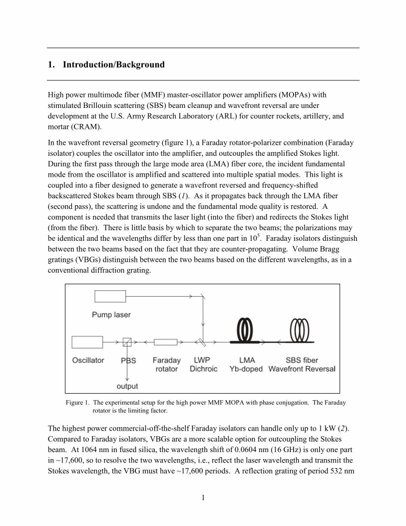
In the wavefront reversal geometry (figure 1), a Faraday rotator-polarizer combination (Faraday isolator) couples the oscillator into the amplifier, and outcouples the amplified Stokes light. During the first pass through the large mode area (LMA) fiber core, the incident fundamental mode from the oscillator is amplified and scattered into multiple spatial modes. This light is coupled into a fiber designed to generate a wavefront reversed and frequency-shifted backscattered Stokes beam through SBS (1). As it propagates back through the LMA fiber (second pass), the scattering is undone and the fundamental mode quality is restored. A component is needed that transmits the laser light (into the fiber) and redirects the Stokes light (from the fiber). There is little basis by which to separate the two beams; the polarizations may be identical and the wavelengths differ by less than one part in 105. Faraday isolators distinguish between the two beams based on the fact that they are counter-propagating. Volume Bragg gratings (VBGs) distinguish between the two beams based on the different wavelengths, as in a conventional diffraction grating.
Figure 1. The experimental setup for the high power MMF MOPA with phase conjugation. The Faraday rotator is the limiting factor.
The highest power commercial-off-the-shelf Faraday isolators can handle only up to 1 kW (2). Compared to Faraday isolators, VBGs are a more scalable option for outcoupling the Stokes beam. At 1064 nm in fused silica, the wavelength shift of 0.0604 nm (16 GHz) is only one part in ~17,600, so to resolve the two wavelengths, i.e., reflect the laser wavelength and transmit the Stokes wavelength, the VBG must have ~17,600 periods. A reflection grating of period 532 nm
2
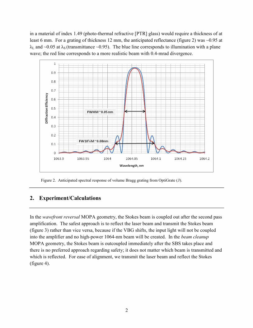
in a material of index 1.49 (photo-thermal refractive [PTR] glass) would require a thickness of at least 6 mm. For a grating of thickness 12 mm, the anticipated reflectance (figure 2) was ~0.95 at λL and ~0.05 at λS (transmittance ~0.95). The blue line corresponds to illumination with a plane wave; the red line corresponds to a more realistic beam with 0.4-mrad divergence.
Figure 2. Anticipated spectral response of volume Bragg grating from OptiGrate (3).
2. Experiment/Calculations
In the wavefront reversal MOPA geometry, the Stokes beam is coupled out after the second pass amplification. The safest approach is to reflect the laser beam and transmit the Stokes beam (figure 3) rather than vice versa, because if the VBG shifts, the input light will not be coupled into the amplifier and no high-power 1064-nm beam will be created. In the beam cleanup MOPA geometry, the Stokes beam is outcoupled immediately after the SBS takes place and there is no preferred approach regarding safety; it does not matter which beam is transmitted and which is reflected. For ease of alignment, we transmit the laser beam and reflect the Stokes (figure 4).
3
Figure 3. Using a VBG to outcouple in the wavefront reversal geometry. This geometry is safer than transmitting λL and reflecting λS.
Figure 4. A possible configuration to outcouple in the beam cleanup geometry. It is equally appropriate to reflect λL and transmit λS.
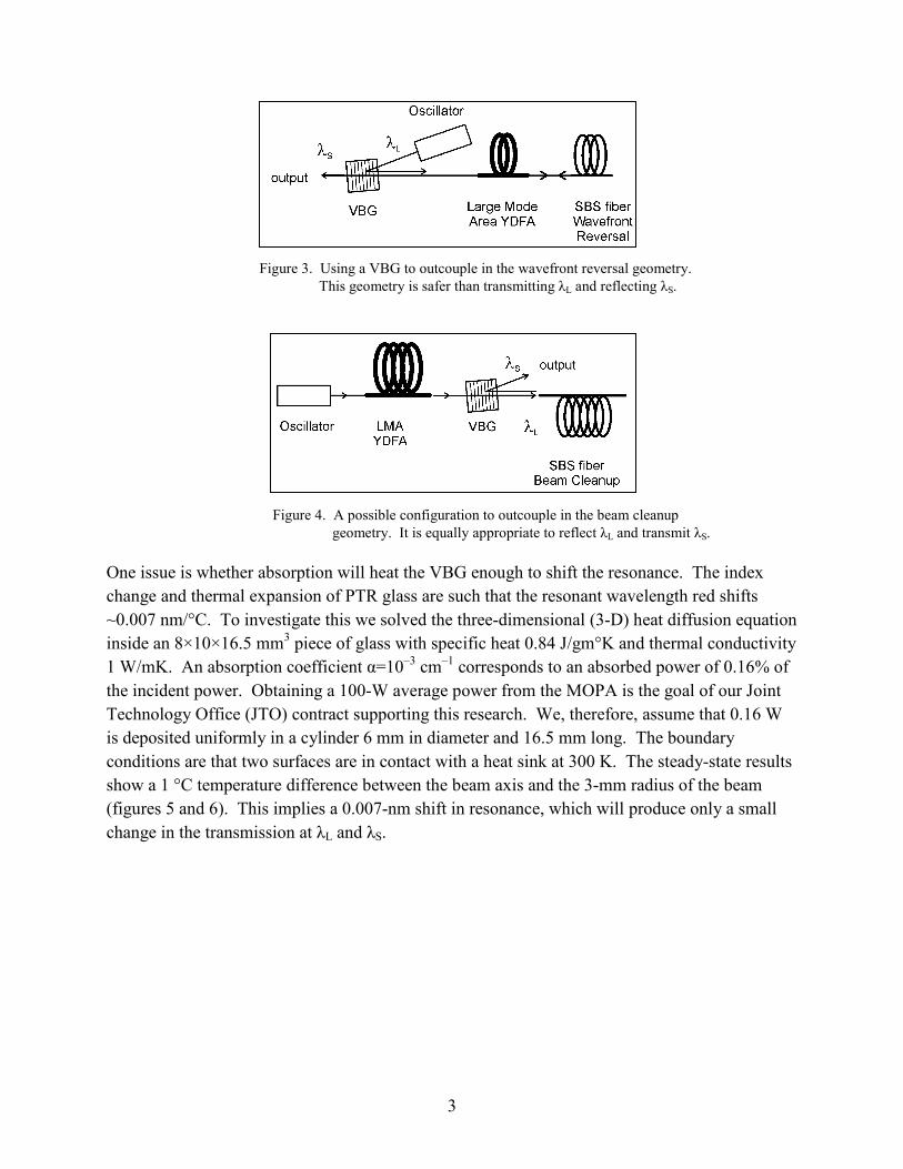
One issue is whether absorption will heat the VBG enough to shift the resonance. The index change and thermal expansion of PTR glass are such that the resonant wavelength red shifts ~0.007 nm/°C. To investigate this we solved the three-dimensional (3-D) heat diffusion equation inside an 8×10×16.5 mm3 piece of glass with specific heat 0.84 J/gm°K and thermal conductivity 1 W/mK. An absorption coefficient α=10–3 cm–1 corresponds to an absorbed power of 0.16% of the incident power. Obtaining a 100-W average power from the MOPA is the goal of our Joint Technology Office (JTO) contract supporting this research. We, therefore, assume that 0.16 W is deposited uniformly in a cylinder 6 mm in diameter and 16.5 mm long. The boundary conditions are that two surfaces are in contact with a heat sink at 300 K. The steady-state results show a 1 °C temperature difference between the beam axis and the 3-mm radius of the beam (figures 5 and 6). This implies a 0.007-nm shift in resonance, which will produce only a small change in the transmission at λL and λS.
4
Figure 5. Steady-state temperature profile inside an 8×10×16.5 mm3 piece of PTR glass, with 0.16 W of heat deposited in a cylinder of the same length and 6 mm in diameter.
300.00
300.50
301.00
301.50
302.00
0 .4 .8 1.2 1.6 2 2.4 2.8 3.2 3.6 4
Tem
p (K
elvi
n)
Along Y (mm)
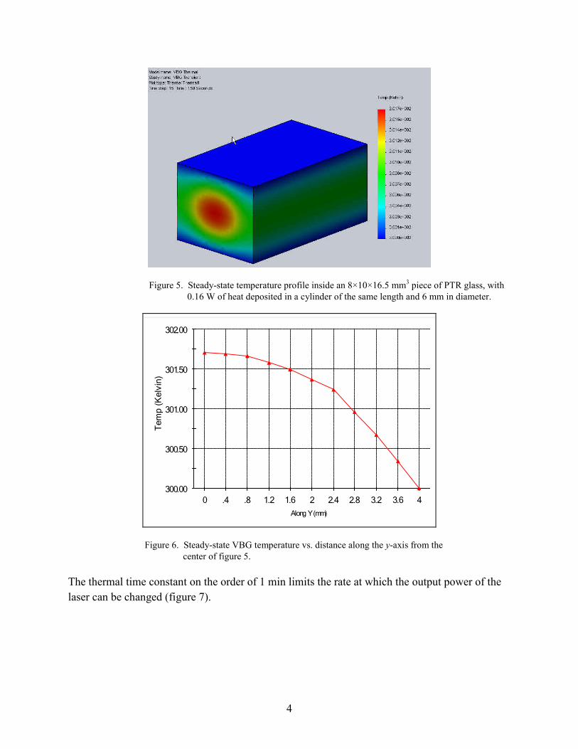
Figure 6. Steady-state VBG temperature vs. distance along the y-axis from the center of figure 5.
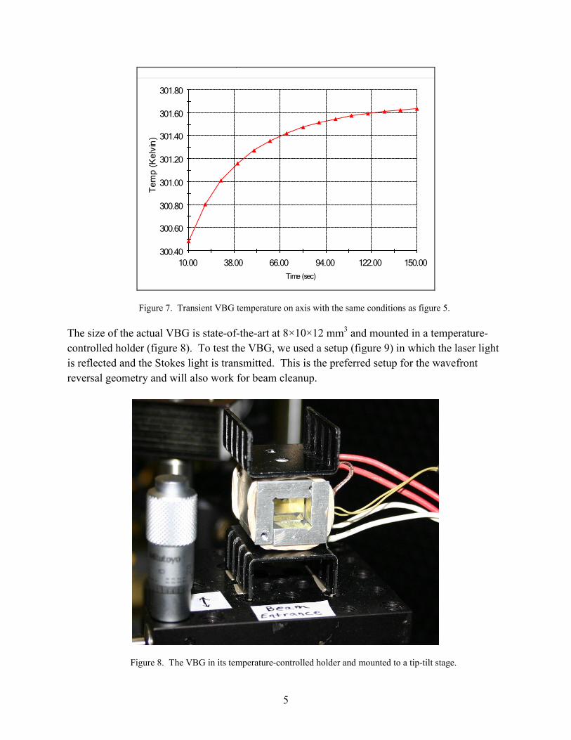
The thermal time constant on the order of 1 min limits the rate at which the output power of the laser can be changed (figure 7).
5
300.40
300.60
300.80
301.00
301.20
301.40
301.60
301.80
10.00 38.00 66.00 94.00 122.00 150.00
Tem
p (K
elvi
n)
Time (sec)
yp
Figure 7. Transient VBG temperature on axis with the same conditions as figure 5.
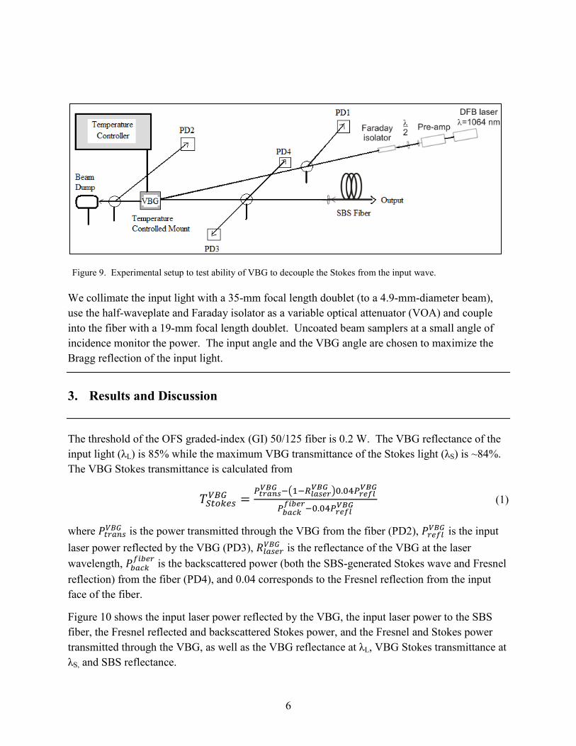
The size of the actual VBG is state-of-the-art at 8×10×12 mm3 and mounted in a temperature-controlled holder (figure 8). To test the VBG, we used a setup (figure 9) in which the laser light is reflected and the Stokes light is transmitted. This is the preferred setup for the wavefront reversal geometry and will also work for beam cleanup.
Figure 8. The VBG in its temperature-controlled holder and mounted to a tip-tilt stage.
6
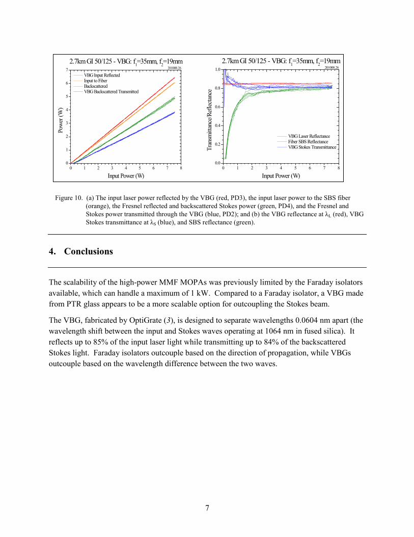
Figure 9. Experimental setup to test ability of VBG to decouple the Stokes from the input wave.
We collimate the input light with a 35-mm focal length doublet (to a 4.9-mm-diameter beam), use the half-waveplate and Faraday isolator as a variable optical attenuator (VOA) and couple into the fiber with a 19-mm focal length doublet. Uncoated beam samplers at a small angle of incidence monitor the power. The input angle and the VBG angle are chosen to maximize the Bragg reflection of the input light.
3. Results and Discussion
The threshold of the OFS graded-index (GI) 50/125 fiber is 0.2 W. The VBG reflectance of the input light (λL) is 85% while the maximum VBG transmittance of the Stokes light (λS) is ~84%. The VBG Stokes transmittance is calculated from
𝑇𝑆𝑡𝑜𝑘𝑒𝑠𝑉𝐵𝐺 =𝑃𝑡𝑟𝑎𝑛𝑠𝑉𝐵𝐺 −�1−𝑅𝑙𝑎𝑠𝑒𝑟
𝑉𝐵𝐺 �0.04𝑃𝑟𝑒𝑓𝑙𝑉𝐵𝐺
𝑃𝑏𝑎𝑐𝑘𝑓𝑖𝑏𝑒𝑟−0.04𝑃𝑟𝑒𝑓𝑙
𝑉𝐵𝐺 (1)
where 𝑃𝑡𝑟𝑎𝑛𝑠𝑉𝐵𝐺 is the power transmitted through the VBG from the fiber (PD2), 𝑃𝑟𝑒𝑓𝑙𝑉𝐵𝐺 is the input laser power reflected by the VBG (PD3), 𝑅𝑙𝑎𝑠𝑒𝑟𝑉𝐵𝐺 is the reflectance of the VBG at the laser wavelength, 𝑃𝑏𝑎𝑐𝑘
𝑓𝑖𝑏𝑒𝑟 is the backscattered power (both the SBS-generated Stokes wave and Fresnel reflection) from the fiber (PD4), and 0.04 corresponds to the Fresnel reflection from the input face of the fiber.
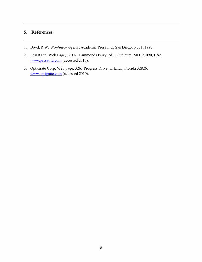
Figure 10 shows the input laser power reflected by the VBG, the input laser power to the SBS fiber, the Fresnel reflected and backscattered Stokes power, and the Fresnel and Stokes power transmitted through the VBG, as well as the VBG reflectance at λL, VBG Stokes transmittance at λS, and SBS reflectance.
7
0 1 2 3 4 5 6 7 80
1
2
3
4
5
6
7 VBG Input Reflected Input to Fiber Backscattered VBG Backscattered Transmitted
2.7km GI 50/125 - VBG: f1=35mm, f2=19mmPo
wer
(W)
Input Power (W)
201008.26
0 1 2 3 4 5 6 7 80.0
0.2
0.4
0.6
0.8
1.0
VBG Laser Reflectance Fiber SBS Reflectance VBG Stokes Transmittance
2.7km GI 50/125 - VBG: f1=35mm, f2=19mm
Tran
smitt
ance
/Ref
lectan
ce
Input Power (W)
201008.26
Figure 10. (a) The input laser power reflected by the VBG (red, PD3), the input laser power to the SBS fiber
(orange), the Fresnel reflected and backscattered Stokes power (green, PD4), and the Fresnel and Stokes power transmitted through the VBG (blue, PD2); and (b) the VBG reflectance at λL (red), VBG Stokes transmittance at λS (blue), and SBS reflectance (green).
4. Conclusions
The scalability of the high-power MMF MOPAs was previously limited by the Faraday isolators available, which can handle a maximum of 1 kW. Compared to a Faraday isolator, a VBG made from PTR glass appears to be a more scalable option for outcoupling the Stokes beam.
The VBG, fabricated by OptiGrate (3), is designed to separate wavelengths 0.0604 nm apart (the wavelength shift between the input and Stokes waves operating at 1064 nm in fused silica). It reflects up to 85% of the input laser light while transmitting up to 84% of the backscattered Stokes light. Faraday isolators outcouple based on the direction of propagation, while VBGs outcouple based on the wavelength difference between the two waves.
8
5. References
1. Boyd, R.W. Nonlinear Optics; Academic Press Inc., San Diego, p 331, 1992.
2. Passat Ltd. Web Page, 720 N. Hammonds Ferry Rd., Linthicum, MD 21090, USA. www.passatltd.com (accessed 2010).
3. OptiGrate Corp. Web page, 3267 Progress Drive, Orlando, Florida 32826. www.optigrate.com (accessed 2010).
9
List of Symbols, Abbreviations, and Acronyms
3-D three-dimensional
ARL U.S. Army Research Laboratory
CRAM counter rockets, artillery, and mortar
GI graded-index
JTO Joint Technology Office
LMA large mode area
MMF multimode fiber
MOPA master-oscillator passive-amplifier
PTR photo-thermal refractive
SBS stimulated Brillouin scattering
VBG volume Bragg grating
VOA variable optical attenuator
10
No. of Copies Organization 1 ADMNSTR ELECT DEFNS TECHL INFO CTR ATTN DTIC OCP 8725 JOHN J KINGMAN RD STE 0944 FT BELVOIR VA 22060-6218 1 CD OFC OF THE SECY OF DEFNS ATTN ODDRE (R&AT) THE PENTAGON WASHINGTON DC 20301-3080 1 US ARMY RSRCH DEV AND ENGRG CMND
ARMAMENT RSRCH DEV AND ENGRG CTR
ARMAMENT ENGRG AND TECHNLGY CTR ATTN AMSRD AAR AEF T J MATTS BLDG 305 ABERDEEN PROVING GROUND MD 21005-5001 1 PM TIMS, PROFILER (MMS-P) AN/TMQ-52 ATTN B GRIFFIES BUILDING 563 FT MONMOUTH NJ 07703 1 US ARMY INFO SYS ENGRG CMND ATTN AMSEL IE TD A RIVERA FT HUACHUCA AZ 85613-5300 1 COMMANDER US ARMY RDECOM
ATTN AMSRD AMR W C MCCORKLE
5400 FOWLER RD REDSTONE ARSENAL AL 35898-5000
No. of Copies Organization 1 US GOVERNMENT PRINT OFF DEPOSITORY RECEIVING SECTION ATTN MAIL STOP IDAD J TATE 732 NORTH CAPITOL ST NW WASHINGTON DC 20402 1 US ARMY RSRCH LAB ATTN RDRL CIM G T LANDFRIED BLDG 4600 ABERDEEN PROVING GROUND MD 21005-5066 15 US ARMY RSRCH LAB ATTN IMNE ALC HRR MAIL & RECORDS MGMT ATTN RDRL CIM L TECHL LIB ATTN RDRL CIM P TECHL PUB ATTN RDRL SEE O J E MCELHENNY ATTN RDRL SEE O J WHITE (6 COPIES) ATTN RDRL SEE O J ZHANG ATTN RDRL SEE O L MERKLE ATTN RDRL SEE O M DUBINSKIY ATTN RDRL SEE O N TER-GABRIELYAN ATTN RDRL SEE O T SANAMYAN ADELPHI MD 20783-1197 TOTAL: 24 (1 ELECT, 1 CD 22 HCS)


![Microindentation Sensor System Based ... - Fiber Bragg Grating · characterizations with high spatial resolution. An integrated fiber Bragg grating (FBG) acts as a force sensor [25]](https://img.pdfslide.us/doc/110x75/5eb728e156b9257755281a1a/microindentation-sensor-system-based-fiber-bragg-grating-characterizations.jpg)