Embed Size (px)
Citation preview
17
Fiber-Bragg-Grating Based Optical Amplifiers
Shien-Kuei Liaw1, Kuang-Yu Hsu2, Kuei-Chu Hsu3 and Peng-Chun Peng4
1National Taiwan University of Science and Technology 2National Taiwan University 3National Central University
4National Taipei University of Technology
Taiwan
1. Introduction
In this chapter, we propose several schemes for fiber amplifiers which are all using fiber Bragg gratings (FBGs) as the key elements for their advantages of better uniformity, higher contrast ratio and lower cost. Several applications using FBG-based fiber amplifiers are also introduced. Therefore, this chapter initiates the overview of FBGs characteristics in Sec. 1, then addresses the FBGs playing solo-function roles in the fiber amplifiers in Sec. 2. The examples are like gain equalizer, dispersion compensator, signal reflector, pump reflector and other purposes. Next, Sec. 3 addresses the FBGs playing multiple-function roles in the hybrid fiber amplifiers. It is based on the construction of a C-band erbium-doped fiber amplifier (EDFA) and an L-band Raman fiber amplifier (RFA). The serial type, parallel type, bridge type and bidirectional C + L band hybrid amplifiers using single-wavelength pump laser diodes are proposed. Dispersion management and gain equalization among the C+L-band channels are realized simultaneously. Pump reflectors and double-pass schemes are used to increase the slope efficiency. Signal power variation among the channels are reduced by varying the reflectivities of these corresponding FBGs. Sec. 4 deals with FBG-based optical network devices with built-in fiber amplifier. Such networks devices include the reconfigurable optical add-drop multiplexer (ROADM) either in unidirectional or bidirectional transmission scheme, and the optical cross-connect (OXC) device is also proposed. Power compensation are realized with a bulit-in fiber amplifier. After various kinds of FBG-based fiber amplifiers are discussed, we summarize this chapter and conclude their potential utilization within optical communications and optical sensing.
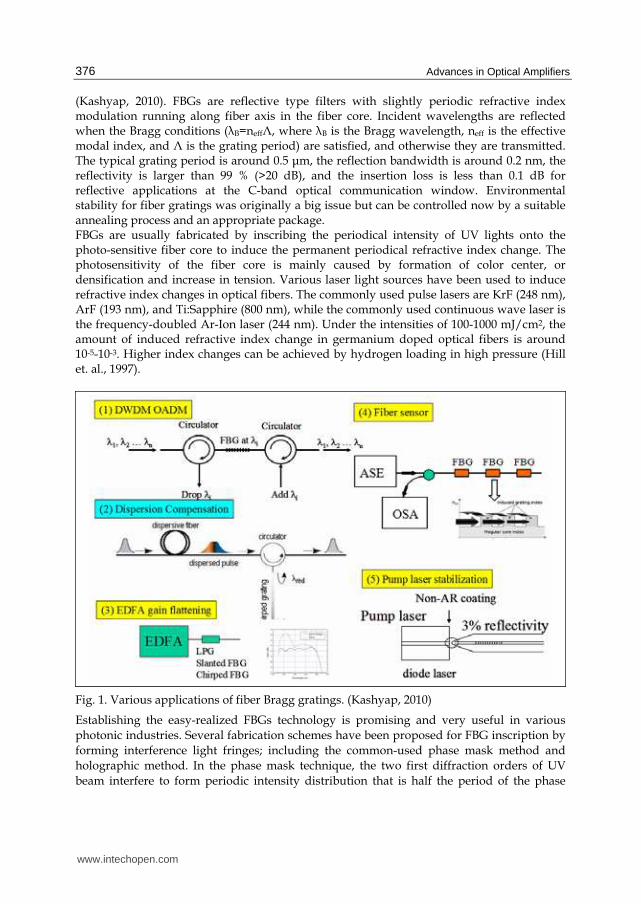
2. Overview of FBGs characteristics 2.1 Introduction to Fiber Bragg Gratings The fiber Bragg gratings (FBGs) research can be dating back to Ken Hill in 1978, and they were initially fabricated using a visible laser propagating along the fiber core. Then holographic technique was demonstrated using the interference pattern of ultraviolet laser light to create the periodic structure of the Bragg grating. Due to all-fiber geometry, FBGs have found important applications such as gain equalizer, dispersion compensator, pump reflector and other purposes as the telecommunication industry grew, as shown in Fig. 1
www.intechopen.com
Advances in Optical Amplifiers
376
(Kashyap, 2010). FBGs are reflective type filters with slightly periodic refractive index modulation running along fiber axis in the fiber core. Incident wavelengths are reflected when the Bragg conditions (┣B=neffΛ, where ┣B is the Bragg wavelength, neff is the effective modal index, and Λ is the grating period) are satisfied, and otherwise they are transmitted. The typical grating period is around 0.5 ┤m, the reflection bandwidth is around 0.2 nm, the reflectivity is larger than 99 % (>20 dB), and the insertion loss is less than 0.1 dB for reflective applications at the C-band optical communication window. Environmental stability for fiber gratings was originally a big issue but can be controlled now by a suitable annealing process and an appropriate package. FBGs are usually fabricated by inscribing the periodical intensity of UV lights onto the photo-sensitive fiber core to induce the permanent periodical refractive index change. The photosensitivity of the fiber core is mainly caused by formation of color center, or densification and increase in tension. Various laser light sources have been used to induce refractive index changes in optical fibers. The commonly used pulse lasers are KrF (248 nm), ArF (193 nm), and Ti:Sapphire (800 nm), while the commonly used continuous wave laser is the frequency-doubled Ar-Ion laser (244 nm). Under the intensities of 100-1000 mJ/cm2, the amount of induced refractive index change in germanium doped optical fibers is around 10-5-10-3. Higher index changes can be achieved by hydrogen loading in high pressure (Hill et. al., 1997).
Fig. 1. Various applications of fiber Bragg gratings. (Kashyap, 2010)
Establishing the easy-realized FBGs technology is promising and very useful in various
photonic industries. Several fabrication schemes have been proposed for FBG inscription by
forming interference light fringes; including the common-used phase mask method and
holographic method. In the phase mask technique, the two first diffraction orders of UV
beam interfere to form periodic intensity distribution that is half the period of the phase
www.intechopen.com
Fiber-Bragg-Grating Based Optical Amplifiers
377
mask, and the zero order beam is totally suppressed. The advantages of the phase mask
approach are the easy alignment, low stability requirement, and low coherence laser source
requirement. Its drawback, which is the advantage of the holographic approach, is the lack
of flexible wavelength tuning capability and the limitation of the grating length. However,
the highly environmental requirement is exactly the drawback of the holographic approach.
Fiber gratings have various kinds of grating structures. For a phase-shifted FBG, a ┨ phase
shift is inserted into the center of the exposure fiber grating during the fabrication process,
and there is a narrow transmission peak within the stop-band due to the resonance caused
by the ┨ phase shift. Chirped fiber grating in general has a non-uniform period along fiber
length, and its phase information can also be contributed from the dc-index change, phase
shift and period change. Chirped gratings can be used as dispersion compensators, for they
are designed to introduce a time delay as a function of wavelength, so that different
wavelength is reflected at a different grating location to achieve wavelength-dependent
group delay. Fiber grating with periods as few hundred micrometers is called long period
gratings (LPGs). They are transmission gratings, which couple light from forward-
propagating guided modes to the forward-propagating cladding modes and the radiation
field. LPGs are particularly useful for equalizing the gain of optical fiber amplifiers, and
they are also good sensors with operation relies on resonance wavelength shift
corresponding to environmental perturbations of strain and temperature.
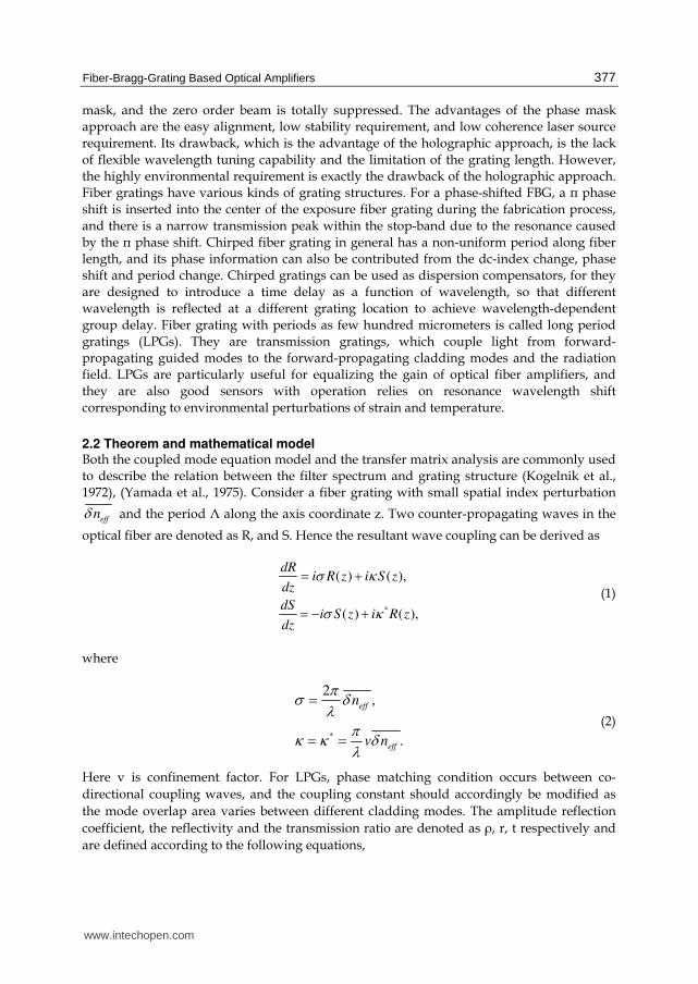
2.2 Theorem and mathematical model Both the coupled mode equation model and the transfer matrix analysis are commonly used
to describe the relation between the filter spectrum and grating structure (Kogelnik et al.,
1972), (Yamada et al., 1975). Consider a fiber grating with small spatial index perturbation
δeffn and the period Λ along the axis coordinate z. Two counter-propagating waves in the
optical fiber are denoted as R, and S. Hence the resultant wave coupling can be derived as
*
( ) ( ),
( ) ( ),
dRi R z i S z
dz
dSi S z i R z
dz
σ κσ κ
= += − +
(1)
where
*
2,
.
eff
eff
n
v n
πσ δλ πκ κ δλ
== =
(2)
Here v is confinement factor. For LPGs, phase matching condition occurs between co-
directional coupling waves, and the coupling constant should accordingly be modified as
the mode overlap area varies between different cladding modes. The amplitude reflection
coefficient, the reflectivity and the transmission ratio are denoted as ┩, r, t respectively and
are defined according to the following equations,
www.intechopen.com
Advances in Optical Amplifiers
378
2
( )2 ,
( )2
,
1 .
ρ
ρ
−= −== −
LS
LR
r
t r
(3)
The transfer matrix method is a simple way to analyzing complex grating structures by dividing the gratings into small sections with constant period and uniform refractive index modulation. The transform matrix yields the following relationship between the reflected wave u and transmitted wave v,
1 1
11 12
21 22
u( ) (0) (0).....
v( ) (0) (0)
(0),
(0)
−⎡ ⎤ ⎡ ⎤ ⎡ ⎤= ⋅ ⋅ ⋅ =⎢ ⎥ ⎢ ⎥ ⎢ ⎥⎣ ⎦ ⎣ ⎦ ⎣ ⎦
⎡ ⎤ ⎡ ⎤= ⎢ ⎥ ⎢ ⎥⎣ ⎦⎣ ⎦
N N
L u uT T T T
L v v
T T u
T T v
(4)
where u(0) and u(L) represent the input and output forward-propagating waves, v(0) and v(L) are the input and output backward-propagating waves, and L is the length of the
grating. The matrix T is a function of the refractive index modulation Δn, and the matrices T1, T2, ….,TN are governed by the parameters of every grating section. The matrix product of T11, T12, T21, T22 forms the final transform matrix. The transmission ratio of the grating can be calculated by
11
( ) 1/t Tδ = (5)
where δ is the frequency detuning. Inverse methods such as layer-peeling method or evolutionary programming synthesis can find complex coupling coefficient of a FBG from the reflection spectrum (Lee et al., 2002).
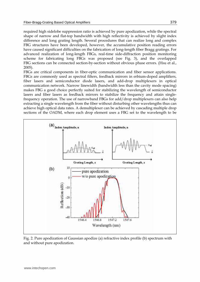
2.3 Fiber grating fabrication technology development and applications The uniform FBG reflection spectrum possesses apparent side-lobes and thus the FBG refractive index envelopes are usually apodized to be of a gaussian or cosine square shape in order to diminish the side-lobes. The quasi-periodic structure on the long wavelength side originates from the resonance between the abrupt index change of the two ends and can be suppressed by apodizing the index profile. On the other hand, Fabry-Perot resonance between peripheral sections of the grating with apodization cause quasi-periodic structures of the reflection spectrum in shorter wavelengths, which can be reduced by keeping the refractive index constant along the fiber length (pure apodization, see Fig. 2). To keep average refractive index the same throughout the length of the grating, pure-apodization method is used to maintain the dose of the UV radiation the same throughout the fiber length but the fringe pattern is gradually altering (Chuang et al., 2004). Conventional method to achieve pure-apodization relies on double UV exposure. The first exposure is to imprint the interference pattern onto the fiber core, followed by the second scan to keep the total doze along the entire grating length unchanged. FBGs as narrowband filters have important applications in single-longitudinal mode fiber lasers and DWDM systems. The
www.intechopen.com
Fiber-Bragg-Grating Based Optical Amplifiers
379
required high sidelobe suppression ratio is achieved by pure apodization, while the spectral shape of narrow and flat-top bandwidth with high reflectivity is achieved by slight index difference and long grating length. Several procedures that can realize long and complex FBG structures have been developed, however, the accumulative position reading errors have caused significant difficulties on the fabrication of long-length fiber Bragg gratings. For advanced realization of long-length FBGs, real-time side-diffraction position monitoring scheme for fabricating long FBGs was proposed (see Fig. 3), and the overlapped FBG sections can be connected section-by-section without obvious phase errors. (Hsu et al., 2005). FBGs are critical components in fiber-optic communication and fiber sensor applications. FBGs are commonly used as spectral filters, feedback mirrors in erbium-doped amplifiers, fiber lasers and semiconductor diode lasers, and add-drop multiplexers in optical communication network. Narrow linewidth (bandwidth less than the cavity mode spacing) makes FBG a good choice perfectly suited for stabilizing the wavelength of semiconductor lasers and fiber lasers as feedback mirrors to stabilize the frequency and attain single-frequency operation. The use of narrowband FBGs for add/drop multiplexers can also help extracting a single wavelength from the fiber without disturbing other wavelengths thus can achieve high optical data rates. A demultiplexer can be achieved by cascading multiple drop sections of the OADM, where each drop element uses a FBG set to the wavelength to be
Fig. 2. Pure apodization of Gaussian apodize (a) refractive index profile (b) spectrum with and without pure apodization.
www.intechopen.com

Advances in Optical Amplifiers
380
Fig. 3. Interferometric side-diffraction position monitoring technique for writing long fiber Bragg gratings. (Hsu et al., 2005)
demultiplexed. Conversely, a multiplexer can be achieved by cascading multiple add sections of the OADM. FBG demultiplexers and OADMs can also be tunable. Narrow-band FBGs at two ends of rare-earth-doped fibers form Fabry-Perot laser cavities as DFB (distributed feedback) lasers that support single-longitudinal mode operation (Qiu et al., 2005). DBR (distributed Bragg reflector) fiber laser is obtained by putting a ┨-phase-shifted grating on the rare-earth-doped fibers, so that the grating is treated as a narrow-band transmission filter. In high-power fiber laser systems, the high and low reflectors are mission-critical elements that have a significant impact on the system's performance and reliability. Semiconductor diode laser with short cavity length results a stable single-frequency operation; and the output is coupled into an optical fiber with low reflectivity FBGs (2-4%) incorporated in output fiber end under external feedback mechanism to efficiently suppress mode hopping and reduce output noise (Archambault et al., 1997). For the applications in EDFAs, FBGs are quite useful for gain-flattening, pump reflection and wavelength stabilization. To maintain a reasonable amount of population inversion in the gain medium, a counter-propagating amplifier configuration is used for optimum power conversion efficiency, and the use of a broad, highly reflecting FBG is needed to double pass the pump light in the amplifier. Tilted FBGs and LPGs with proper designs can couple the guided modes into the cladding to attain flattened EDFA gain spectrum. Another method of fiber amplifier gain equalization is obtained by appropriate choice of individual FBG loss within the gain bandwidth. Furthermore, the center wavelength can be fine-tuned by adding stress on the FBGs to change its period, and the wideband tunability of FBGs widely broadens the application area (Liaw et al., 2008). Besides, chirped fiber gratings as dispersion compensators are widely applied in optical communication systems to compensate chromatic dispersion, or compensate anomalous or normal dispersion caused by the nonlinear effects for pulses propagating in the fiber.
www.intechopen.com
Fiber-Bragg-Grating Based Optical Amplifiers
381
3. FBGs play as solo-function role in a fiber amplifier
The fiber Bragg gratings have been widely used in optical amplifier design for achieving various functions. FBG acts as solo function including fixed or dynamic gain equalization, the dispersion compensation, and the signal and pump reflectors are introduced in this section.
3.1 Fixed and dynamic gain equalization The gain equalization of the EDFA in a multi-channel wavelength division multiplex (WDM) system can be realized by using LPG (Vensarkar et al., 1996). The unwanted power is coupled from the guided mode to the cladding modes through the following phase matching condition:
m
co cl mn n
λΛ− = (6)
where con and mcln are the effective core mode index and the cladding mode index,
respectively. m is the order of the cladding mode and λ is the signal wavelength in free
space. mΛ is the grating pitch that attains the phase matching criteria for coupling the core
mode into the m-th cladding mode. Since the index difference between the core mode and
the cladding mode is very small, the typical pitch of the long-period grating is in the order
of several hundreds of micrometers. Arbitrary spectral shape can be realized by cascading
several LPG with appropriate resonance wavelengths and grating strengths. The
transmission spectrum of the gain-flattening filter using two cascaded LPG is shown in
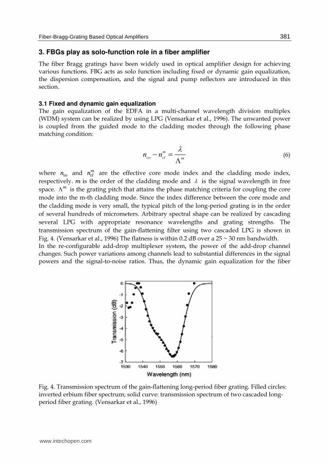
Fig. 4. (Vensarkar et al., 1996) The flatness is within 0.2 dB over a 25 ~ 30 nm bandwidth. In the re-configurable add-drop multiplexer system, the power of the add-drop channel changes. Such power variations among channels lead to substantial differences in the signal powers and the signal-to-noise ratios. Thus, the dynamic gain equalization for the fiber
Fig. 4. Transmission spectrum of the gain-flattening long-period fiber grating. Filled circles: inverted erbium fiber spectrum; solid curve: transmission spectrum of two cascaded long-period fiber grating. (Vensarkar et al., 1996)
www.intechopen.com
Advances in Optical Amplifiers
382
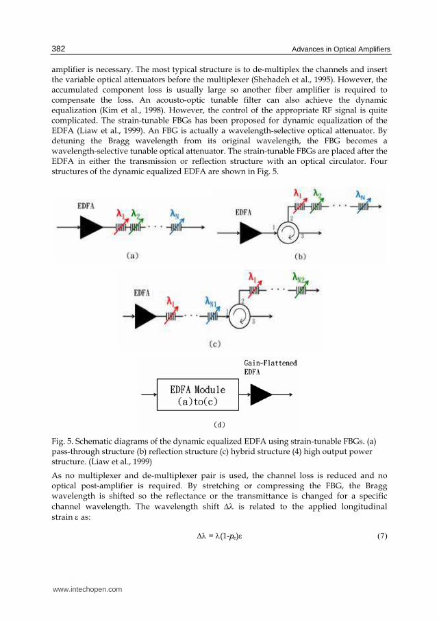
amplifier is necessary. The most typical structure is to de-multiplex the channels and insert the variable optical attenuators before the multiplexer (Shehadeh et al., 1995). However, the accumulated component loss is usually large so another fiber amplifier is required to compensate the loss. An acousto-optic tunable filter can also achieve the dynamic equalization (Kim et al., 1998). However, the control of the appropriate RF signal is quite complicated. The strain-tunable FBGs has been proposed for dynamic equalization of the EDFA (Liaw et al., 1999). An FBG is actually a wavelength-selective optical attenuator. By detuning the Bragg wavelength from its original wavelength, the FBG becomes a wavelength-selective tunable optical attenuator. The strain-tunable FBGs are placed after the EDFA in either the transmission or reflection structure with an optical circulator. Four structures of the dynamic equalized EDFA are shown in Fig. 5.
Fig. 5. Schematic diagrams of the dynamic equalized EDFA using strain-tunable FBGs. (a) pass-through structure (b) reflection structure (c) hybrid structure (4) high output power structure. (Liaw et al., 1999)
As no multiplexer and de-multiplexer pair is used, the channel loss is reduced and no optical post-amplifier is required. By stretching or compressing the FBG, the Bragg wavelength is shifted so the reflectance or the transmittance is changed for a specific
channel wavelength. The wavelength shift Δλ is related to the applied longitudinal
strain ε as:
Δλ = λ(1-pe)ε (7)
www.intechopen.com
Fiber-Bragg-Grating Based Optical Amplifiers
383
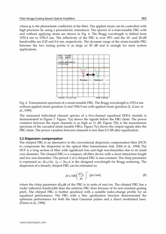
where pe is the photoelastic coefficient of the fiber. The applied strain can be controlled with high precision by using a piezoelectric transducer. The spectra of a train-tunable FBG with and without applying strain are shown in Fig. 6. The Bragg wavelength is shifted from 1555.4 nm to 1556.5 nm. The reflectivity of the FBG is over 99% and the 10- and 20-dB bandwidths are 0.25 and 0.6 nm, respectively. The dynamic range of the strain-tunable FBG between the two tuning points is as large as 20 dB and is enough for most system applications.
Fig. 6. Transmission spectrum of a strain-tunable FBG. The Bragg wavelength is 1555.4 nm without applied strain (position 1) and 1556.5 nm with applied strain (position 2). (Liaw et al., 1999)
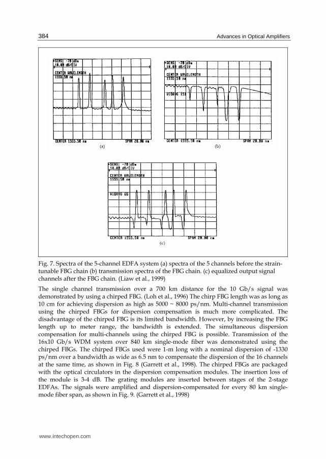
The measured individual channel spectra of a five-channel equalized EDFA module is demonstrated in Figure 7. Figure. 7(a) shows the signals before the FBG chain. The power variation between the input channels is as high as 11 dB. Figure 7(b) is the transmission spectrum of the cascaded strain tunable FBGs. Figure 7(c) shows the output signals after the FBG chain. The power variation between channels is less than 0.3 dB after equalization.
3.2 Dispersion compensation
The chirped FBG is an alternative to the conventional dispersion compensation fiber (DCF) to compensate the dispersion in the optical fiber transmission link. (Hill et al., 1994) The DCF is a long section of fiber with significant loss and high non-linearities due to its small core diameter. The chirped FBG is a compact, all-fiber device with a short interaction length and low non-linearities. The period Λ of a chirped FBG is non-constant. The chirp parameter is expressed as: dλD/dz. λD ≡ 2ncoΛ is the designed wavelength for Bragg scattering. The dispersion of a linearly chirped FBG can be estimated as:
1
100 Dd
Ddz
λ −⎛ ⎞≈ ⎜ ⎟⎝ ⎠ (ps/nm) (8)
where the chirp parameter dλD/dz of the FBG is in units of nm/cm. The chirped FBG has a wider reflection bandwidth than the uniform FBG does because of its non-constant grating pitch. The chirped FBG is further apodized with a suitable index-change profile for an equalized performance. The FBG with a Sinc apodization function demonstrated the optimum performance for both the ideal Gaussian pulses and a direct modulated laser. (Pastor et al., 1996)
www.intechopen.com
Advances in Optical Amplifiers
384
Fig. 7. Spectra of the 5-channel EDFA system (a) spectra of the 5 channels before the strain-tunable FBG chain (b) transmission spectra of the FBG chain. (c) equalized output signal channels after the FBG chain. (Liaw et al., 1999)
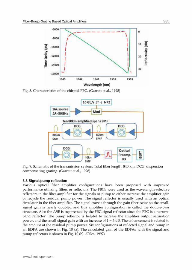
The single channel transmission over a 700 km distance for the 10 Gb/s signal was demonstrated by using a chirped FBG. (Loh et al., 1996) The chirp FBG length was as long as 10 cm for achieving dispersion as high as 5000 ~ 8000 ps/nm. Multi-channel transmission using the chirped FBGs for dispersion compensation is much more complicated. The disadvantage of the chirped FBG is its limited bandwidth. However, by increasing the FBG length up to meter range, the bandwidth is extended. The simultaneous dispersion compensation for multi-channels using the chirped FBG is possible. Transmission of the 16x10 Gb/s WDM system over 840 km single-mode fiber was demonstrated using the chirped FBGs. The chirped FBGs used were 1-m long with a nominal dispersion of -1330 ps/nm over a bandwidth as wide as 6.5 nm to compensate the dispersion of the 16 channels at the same time, as shown in Fig. 8 (Garrett et al., 1998). The chirped FBGs are packaged with the optical circulators in the dispersion compensation modules. The insertion loss of the module is 3-4 dB. The grating modules are inserted between stages of the 2-stage EDFAs. The signals were amplified and dispersion-compensated for every 80 km single-mode fiber span, as shown in Fig. 9. (Garrett et al., 1998)
www.intechopen.com
Fiber-Bragg-Grating Based Optical Amplifiers
385
Fig. 8. Characteristics of the chirped FBG. (Garrett et al., 1998)
Fig. 9. Schematic of the transmission system. Total fiber length: 840 km. DCG: dispersion compensating grating. (Garrett et al., 1998)
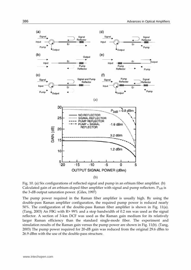
3.3 Signal/pump reflection Various optical fiber amplifier configurations have been proposed with improved performance utilizing filters or reflectors. The FBGs were used as the wavelength-selective reflectors in the fiber amplifier for the signals or pump to either increase the amplifier gain or recycle the residual pump power. The signal reflector is usually used with an optical circulator in the fiber amplifier. The signal travels through the gain fiber twice so the small-signal gain is nearly doubled and this amplifier configuration is called the double-pass structure. Also the ASE is suppressed by the FBG signal reflector since the FBG is a narrow-band reflector. The pump reflector is helpful to increase the amplifier output saturation power, and the small-signal gain with an increase of 1 ~ 3 dB. The enhancement is related to the amount of the residual pump power. Six configurations of reflected signal and pump in an EDFA are shown in Fig. 10 (a). The calculated gain of the EDFAs with the signal and pump reflectors is shown in Fig. 10 (b). (Giles, 1997)
www.intechopen.com
Advances in Optical Amplifiers
386
(a)
(b)
Fig. 10. (a) Six configurations of reflected signal and pump in an erbium fiber amplifier. (b) Calculated gain of an erbium-doped fiber amplifier with signal and pump reflectors. P3dB is the 3-dB output saturation power. (Giles, 1997)
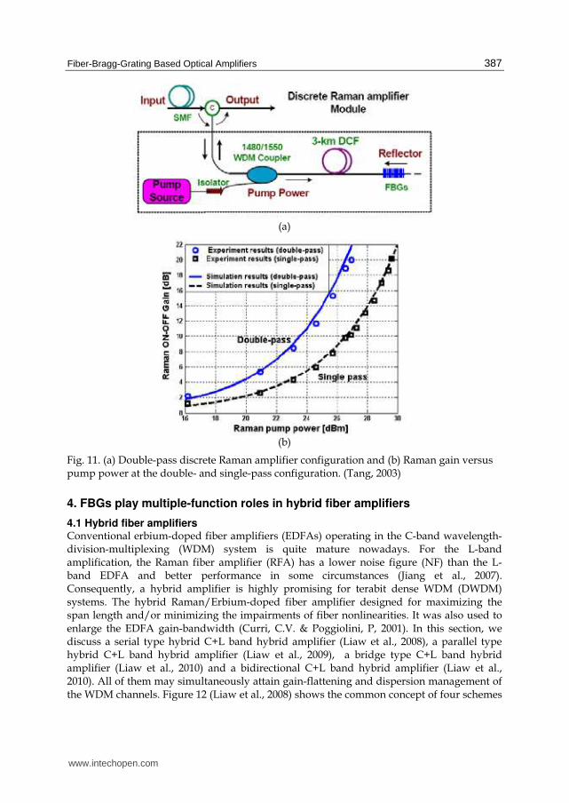
The pump power required in the Raman fiber amplifier is usually high. By using the double-pass Raman amplifier configuration, the required pump power is reduced nearly 50%. The configuration of the double-pass Raman fiber amplifier is shown in Fig. 11(a). (Tang, 2003) An FBG with R> 99% and a stop bandwidth of 0.2 nm was used as the signal reflector. A section of 3-km DCF was used as the Raman gain medium for its relatively larger Raman efficiency than the standard single-mode fiber. The experiment and simulation results of the Raman gain versus the pump power are shown in Fig. 11(b). (Tang, 2003) The pump power required for 20-dB gain was reduced from the original 29.6 dBm to 26.9 dBm with the use of the double-pass structure.
www.intechopen.com
Fiber-Bragg-Grating Based Optical Amplifiers
387
(a)
(b)
Fig. 11. (a) Double-pass discrete Raman amplifier configuration and (b) Raman gain versus pump power at the double- and single-pass configuration. (Tang, 2003)
4. FBGs play multiple-function roles in hybrid fiber amplifiers
4.1 Hybrid fiber amplifiers Conventional erbium-doped fiber amplifiers (EDFAs) operating in the C-band wavelength-division-multiplexing (WDM) system is quite mature nowadays. For the L-band amplification, the Raman fiber amplifier (RFA) has a lower noise figure (NF) than the L-band EDFA and better performance in some circumstances (Jiang et al., 2007). Consequently, a hybrid amplifier is highly promising for terabit dense WDM (DWDM) systems. The hybrid Raman/Erbium-doped fiber amplifier designed for maximizing the span length and/or minimizing the impairments of fiber nonlinearities. It was also used to enlarge the EDFA gain-bandwidth (Curri, C.V. & Poggiolini, P, 2001). In this section, we discuss a serial type hybrid C+L band hybrid amplifier (Liaw et al., 2008), a parallel type hybrid C+L band hybrid amplifier (Liaw et al., 2009), a bridge type C+L band hybrid amplifier (Liaw et al., 2010) and a bidirectional C+L band hybrid amplifier (Liaw et al., 2010). All of them may simultaneously attain gain-flattening and dispersion management of the WDM channels. Figure 12 (Liaw et al., 2008) shows the common concept of four schemes
www.intechopen.com
Advances in Optical Amplifiers
388
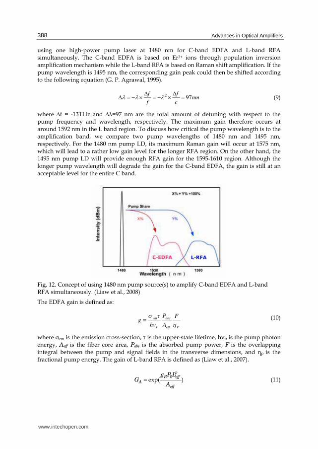
using one high-power pump laser at 1480 nm for C-band EDFA and L-band RFA simultaneously. The C-band EDFA is based on Er3+ ions through population inversion amplification mechanism while the L-band RFA is based on Raman shift amplification. If the pump wavelength is 1495 nm, the corresponding gain peak could then be shifted according to the following equation (G. P. Agrawal, 1995).
297λ λ λΔ ΔΔ = − × = − × =f f
nmf c
(9)
where ∆f = -13THz and ∆┣=97 nm are the total amount of detuning with respect to the pump frequency and wavelength, respectively. The maximum gain therefore occurs at around 1592 nm in the L band region. To discuss how critical the pump wavelength is to the amplification band, we compare two pump wavelengths of 1480 nm and 1495 nm, respectively. For the 1480 nm pump LD, its maximum Raman gain will occur at 1575 nm, which will lead to a rather low gain level for the longer RFA region. On the other hand, the 1495 nm pump LD will provide enough RFA gain for the 1595-1610 region. Although the longer pump wavelength will degrade the gain for the C-band EDFA, the gain is still at an acceptable level for the entire C band.
Fig. 12. Concept of using 1480 nm pump source(s) to amplify C-band EDFA and L-band RFA simultaneously. (Liaw et al., 2008)
The EDFA gain is defined as:
Peff
abs
P
em F
A
P
hvg η
τσ= (10)
where ┫em is the emission cross-section, ┬ is the upper-state lifetime, h┥p is the pump photon energy, Aeff is the fiber core area, Pabs is the absorbed pump power, F is the overlapping integral between the pump and signal fields in the transverse dimensions, and ηp is the fractional pump energy. The gain of L-band RFA is defined as (Liaw et al., 2007).
0
exp( )
pR eff
Aeff
g P LG
A= (11)
www.intechopen.com
Fiber-Bragg-Grating Based Optical Amplifiers
389
where gR is the Raman gain coefficient as the wavelength difference function between the
signal and pump, P0 is the pump power at the amplifier input, and peffL is the effective
pump length.
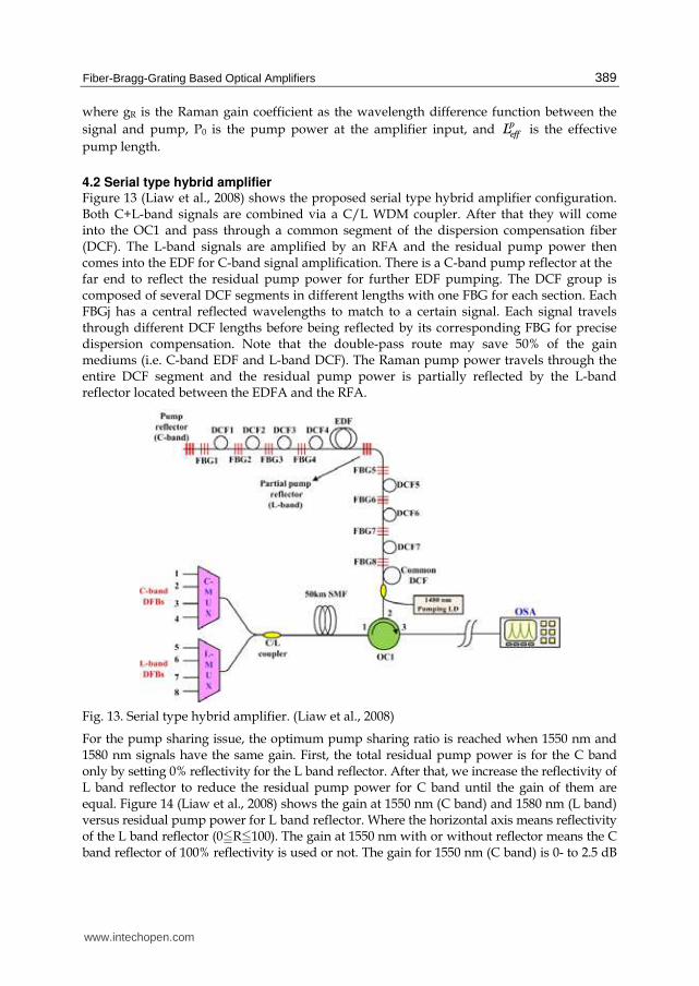
4.2 Serial type hybrid amplifier Figure 13 (Liaw et al., 2008) shows the proposed serial type hybrid amplifier configuration. Both C+L-band signals are combined via a C/L WDM coupler. After that they will come into the OC1 and pass through a common segment of the dispersion compensation fiber (DCF). The L-band signals are amplified by an RFA and the residual pump power then comes into the EDF for C-band signal amplification. There is a C-band pump reflector at the far end to reflect the residual pump power for further EDF pumping. The DCF group is composed of several DCF segments in different lengths with one FBG for each section. Each FBGj has a central reflected wavelengths to match to a certain signal. Each signal travels through different DCF lengths before being reflected by its corresponding FBG for precise dispersion compensation. Note that the double-pass route may save 50% of the gain mediums (i.e. C-band EDF and L-band DCF). The Raman pump power travels through the entire DCF segment and the residual pump power is partially reflected by the L-band reflector located between the EDFA and the RFA.
Fig. 13. Serial type hybrid amplifier. (Liaw et al., 2008)
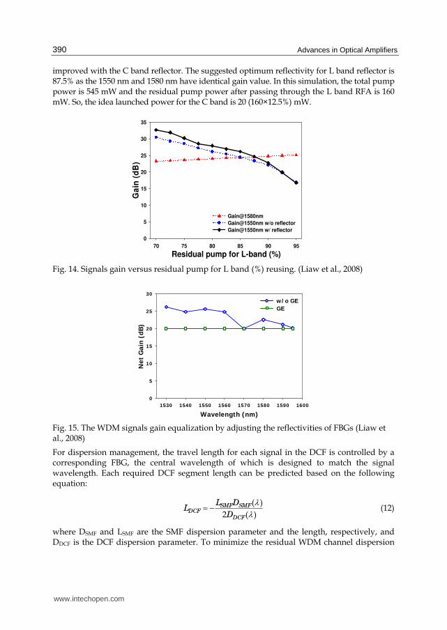
For the pump sharing issue, the optimum pump sharing ratio is reached when 1550 nm and 1580 nm signals have the same gain. First, the total residual pump power is for the C band only by setting 0% reflectivity for the L band reflector. After that, we increase the reflectivity of L band reflector to reduce the residual pump power for C band until the gain of them are equal. Figure 14 (Liaw et al., 2008) shows the gain at 1550 nm (C band) and 1580 nm (L band) versus residual pump power for L band reflector. Where the horizontal axis means reflectivity of the L band reflector (0NRN100). The gain at 1550 nm with or without reflector means the C band reflector of 100% reflectivity is used or not. The gain for 1550 nm (C band) is 0- to 2.5 dB
www.intechopen.com
Advances in Optical Amplifiers
390
improved with the C band reflector. The suggested optimum reflectivity for L band reflector is 87.5% as the 1550 nm and 1580 nm have identical gain value. In this simulation, the total pump power is 545 mW and the residual pump power after passing through the L band RFA is 160 mW. So, the idea launched power for the C band is 20 (160×12.5%) mW.
Residual pump for L-band (%)70 75 80 85 90 95
Ga
in (
dB
)
0
5
10
15
20
25
30
35
Gain@1580nm
Gain@1550nm w/o reflector
Gain@1550nm w/ reflector
Fig. 14. Signals gain versus residual pump for L band (%) reusing. (Liaw et al., 2008)
Wavelength (nm)1530 1540 1550 1560 1570 1580 1590 1600
Ne
t G
ain
(d
B)
0
5
10
15
20
25
30w/ o GEGE
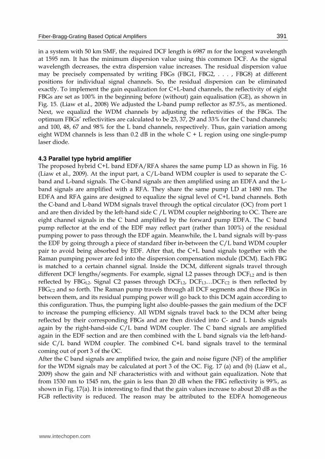
Fig. 15. The WDM signals gain equalization by adjusting the reflectivities of FBGs (Liaw et al., 2008)
For dispersion management, the travel length for each signal in the DCF is controlled by a corresponding FBG, the central wavelength of which is designed to match the signal wavelength. Each required DCF segment length can be predicted based on the following equation:
( )
2 ( )SMF SMF
DCFDCF
L DL
D
λλ= − (12)
where DSMF and LSMF are the SMF dispersion parameter and the length, respectively, and DDCF is the DCF dispersion parameter. To minimize the residual WDM channel dispersion
www.intechopen.com
Fiber-Bragg-Grating Based Optical Amplifiers
391
in a system with 50 km SMF, the required DCF length is 6987 m for the longest wavelength at 1595 nm. It has the minimum dispersion value using this common DCF. As the signal wavelength decreases, the extra dispersion value increases. The residual dispersion value may be precisely compensated by writing FBGs (FBG1, FBG2, . . . , FBG8) at different positions for individual signal channels. So, the residual dispersion can be eliminated exactly. To implement the gain equalization for C+L-band channels, the reflectivity of eight FBGs are set as 100% in the beginning before (without) gain equalisation (GE), as shown in Fig. 15. (Liaw et al., 2008) We adjusted the L-band pump reflector as 87.5%, as mentioned. Next, we equalizd the WDM channels by adjusting the reflectivities of the FBGs. The optimum FBGs’ reflectivities are calculated to be 23, 37, 29 and 33% for the C band channels; and 100, 48, 67 and 98% for the L band channels, respectively. Thus, gain variation among eight WDM channels is less than 0.2 dB in the whole C + L region using one single-pump laser diode.
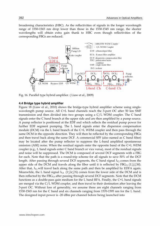
4.3 Parallel type hybrid amplifier The proposed hybrid C+L band EDFA/RFA shares the same pump LD as shown in Fig. 16
(Liaw et al., 2009). At the input part, a C/L-band WDM coupler is used to separate the C-
band and L-band signals. The C-band signals are then amplified using an EDFA and the L-
band signals are amplified with a RFA. They share the same pump LD at 1480 nm. The
EDFA and RFA gains are designed to equalize the signal level of C+L band channels. Both
the C-band and L-band WDM signals travel through the optical circulator (OC) from port 1
and are then divided by the left-hand side C /L WDM coupler neighboring to OC. There are
eight channel signals in the C band amplified by the forward pump EDFA. The C band
pump reflector at the end of the EDF may reflect part (rather than 100%) of the residual
pumping power to pass through the EDF again. Meanwhile, the L band signals will by-pass
the EDF by going through a piece of standard fiber in-between the C/L band WDM coupler
pair to avoid being absorbed by EDF. After that, the C+L band signals together with the
Raman pumping power are fed into the dispersion compensation module (DCM). Each FBG
is matched to a certain channel signal. Inside the DCM, different signals travel through
different DCF lengths/segments. For example, signal L2 passes through DCFL2 and is then
reflected by FBGL2. Signal C2 passes through DCFL2, DCFL3…DCFC2 is then reflected by
FBGC2 and so forth. The Raman pump travels through all DCF segments and those FBGs in
between them, and its residual pumping power will go back to this DCM again according to
this configuration. Thus, the pumping light also double-passes the gain medium of the DCF
to increase the pumping efficiency. All WDM signals travel back to the DCM after being
reflected by their corresponding FBGs and are then divided into C- and L bands signals
again by the right-hand-side C/L band WDM coupler. The C band signals are amplified
again in the EDF section and are then combined with the L band signals via the left-hand-
side C/L band WDM coupler. The combined C+L band signals travel to the terminal
coming out of port 3 of the OC.
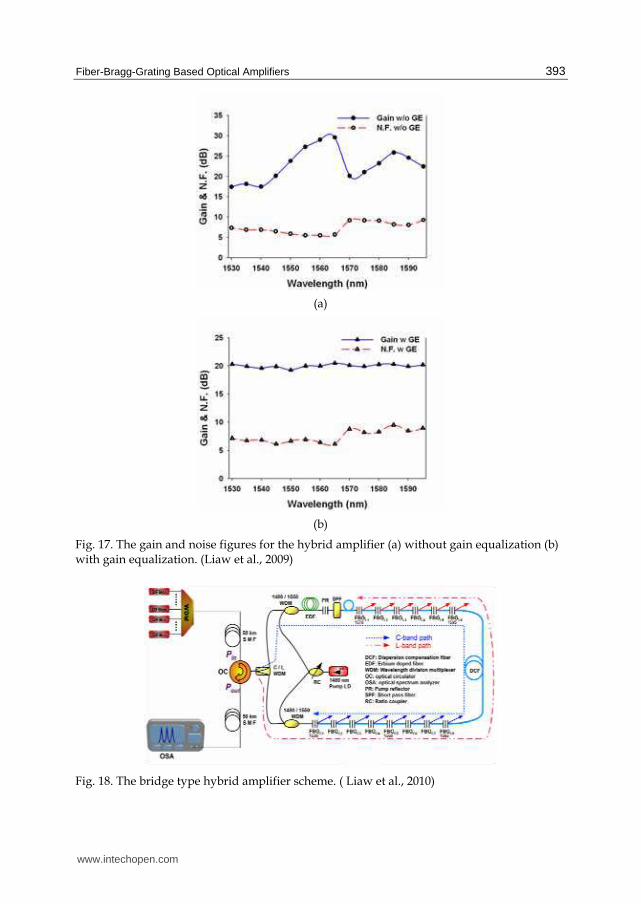
After the C band signals are amplified twice, the gain and noise figure (NF) of the amplifier for the WDM signals may be calculated at port 3 of the OC. Fig. 17 (a) and (b) (Liaw et al., 2009) show the gain and NF characteristics with and without gain equalization. Note that from 1530 nm to 1545 nm, the gain is less than 20 dB when the FBG reflectivity is 99%, as shown in Fig. 17(a). It is interesting to find that the gain values increase to about 20 dB as the FGB reflectivity is reduced. The reason may be attributed to the EDFA homogeneous
www.intechopen.com
Advances in Optical Amplifiers
392
broadening characteristics (HBC). As the reflectivities of signals in the longer wavelength range of 1550-1565 nm drop lower than those in the 1530-1545 nm range, the shorter wavelengths will obtain extra gain thank to HBC even though reflectivities of the corresponding FBGs are reduced.
E DF 2 m
1480nm Pump LD
C-band E DFA
By-pass E DF
R atio coupler
12
3
Inp
ut
C om. DC F
C/L WDM C/L WDM
Pump reflector
L-band Ch. C-band Ch.
:1480/1550 W DM C oupler
: C/L W DM C oupler
E DF : erbium-doped fiber
R F A : R aman fiber amplifier
DC F : dis pers ion compens ation fiber
IS O : is olator
S MF : s ingle mode fiber
P B C : polarization beam combiner
Pump reflector
B
A
COu
tpu
t
DC FC1DC FL2 DC FC2
FBGL1 FBGL2 FBGC1 FBGC2
Fig. 16. Parallel type hybrid amplifier. ( Liaw et al., 2009)
4.4 Bridge type hybrid amplifier
Figure 18 (Liaw et al., 2010) shows the bridge-type hybrid amplifier scheme using single-
wavelength pump source. All C+L band channels reach the 3-port OC after 50 km SMF
transmission and then divided into two groups using a C/L WDM coupler. The C band
signals enter the C band branch at the upper side and are then amplified by a pump source.
A pump reflector is positioned at the EDF end which reflects the residual pump power for
further EDF segment pumping. The L band signals enter the dispersion compensation
module (DCM) via the L band branch of the C+L WDM coupler and then pass through the
same DCM in the opposite direction. They will then be reflected by the corresponding FBGs
and then travel back along the same DCF. A commercial SPF (also named as C band filter)
may be located after the pump reflector to suppress the L-band amplified spontaneous
emission (ASE) noise. When the residual signals enter the opposite band of the C+L WDM
coupler (e.g., L band signals enter C band branch or vice versa), most of the residual signals
and noise will be suppressed. The DCM is composed of several DCF segments with a FBG
for each. Note that the path is a round-trip scheme for all signals to save 50% of the DCF
length. After passing through several DCF segments, the C band signal ┣Cj comes from the
upper side of the DCM and travels along the fiber until it is reflected by FBGCj (1NjNM).
After that, ┣Cj will travel back along the same path and then be amplified by EDFA again.
Meanwhile, the L band signal ┣Lk (1NkNN) comes from the lower side of the DCM and is
then reflected by the FBGLk after passing through several DCF segments. Note that the DCM
functions as a double-pass gain medium for the L band RFA. Finally, the C+L band signals
are merged via the C/L WDM coupler, and then travel to their destination after leaving the
3-port OC. Without loss of generality, we assume there are eight channels ranging from
1530-1565 nm for the C band and six channels ranging from 1570-1595 nm for the L band.
The designed input power is -20 dBm per channel before being launched into
www.intechopen.com
Fiber-Bragg-Grating Based Optical Amplifiers
393
(a)
(b)
Fig. 17. The gain and noise figures for the hybrid amplifier (a) without gain equalization (b) with gain equalization. (Liaw et al., 2009)
Fig. 18. The bridge type hybrid amplifier scheme. ( Liaw et al., 2010)
www.intechopen.com
Advances in Optical Amplifiers
394
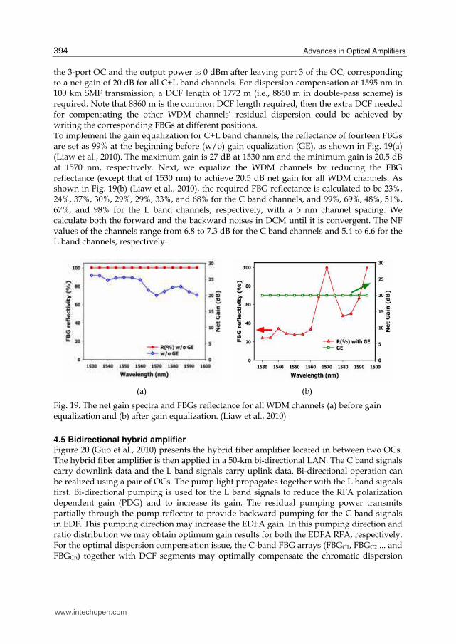
the 3-port OC and the output power is 0 dBm after leaving port 3 of the OC, corresponding to a net gain of 20 dB for all C+L band channels. For dispersion compensation at 1595 nm in 100 km SMF transmission, a DCF length of 1772 m (i.e., 8860 m in double-pass scheme) is required. Note that 8860 m is the common DCF length required, then the extra DCF needed for compensating the other WDM channels’ residual dispersion could be achieved by writing the corresponding FBGs at different positions. To implement the gain equalization for C+L band channels, the reflectance of fourteen FBGs are set as 99% at the beginning before (w/o) gain equalization (GE), as shown in Fig. 19(a) (Liaw et al., 2010). The maximum gain is 27 dB at 1530 nm and the minimum gain is 20.5 dB at 1570 nm, respectively. Next, we equalize the WDM channels by reducing the FBG reflectance (except that of 1530 nm) to achieve 20.5 dB net gain for all WDM channels. As shown in Fig. 19(b) (Liaw et al., 2010), the required FBG reflectance is calculated to be 23%, 24%, 37%, 30%, 29%, 29%, 33%, and 68% for the C band channels, and 99%, 69%, 48%, 51%, 67%, and 98% for the L band channels, respectively, with a 5 nm channel spacing. We calculate both the forward and the backward noises in DCM until it is convergent. The NF values of the channels range from 6.8 to 7.3 dB for the C band channels and 5.4 to 6.6 for the L band channels, respectively.
(a) (b)
Fig. 19. The net gain spectra and FBGs reflectance for all WDM channels (a) before gain equalization and (b) after gain equalization. (Liaw et al., 2010)
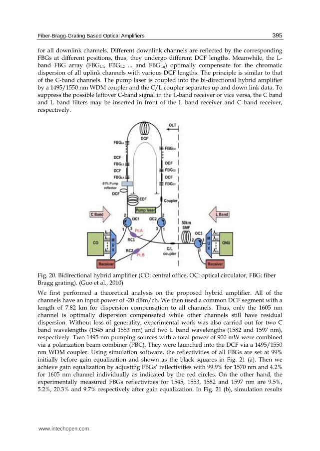
4.5 Bidirectional hybrid amplifier Figure 20 (Guo et al., 2010) presents the hybrid fiber amplifier located in between two OCs. The hybrid fiber amplifier is then applied in a 50-km bi-directional LAN. The C band signals carry downlink data and the L band signals carry uplink data. Bi-directional operation can be realized using a pair of OCs. The pump light propagates together with the L band signals first. Bi-directional pumping is used for the L band signals to reduce the RFA polarization dependent gain (PDG) and to increase its gain. The residual pumping power transmits partially through the pump reflector to provide backward pumping for the C band signals in EDF. This pumping direction may increase the EDFA gain. In this pumping direction and ratio distribution we may obtain optimum gain results for both the EDFA RFA, respectively. For the optimal dispersion compensation issue, the C-band FBG arrays (FBGC1, FBGC2 ... and FBGCn) together with DCF segments may optimally compensate the chromatic dispersion
www.intechopen.com
Fiber-Bragg-Grating Based Optical Amplifiers
395
for all downlink channels. Different downlink channels are reflected by the corresponding FBGs at different positions, thus, they undergo different DCF lengths. Meanwhile, the L-band FBG array (FBGL1, FBGL2 ... and FBGLn) optimally compensate for the chromatic dispersion of all uplink channels with various DCF lengths. The principle is similar to that of the C-band channels. The pump laser is coupled into the bi-directional hybrid amplifier by a 1495/1550 nm WDM coupler and the C/L coupler separates up and down link data. To suppress the possible leftover C-band signal in the L-band receiver or vice versa, the C band and L band filters may be inserted in front of the L band receiver and C band receiver, respectively.
Fig. 20. Bidirectional hybrid amplifier (CO: central office, OC: optical circulator, FBG: fiber Bragg grating). (Guo et al., 2010)
We first performed a theoretical analysis on the proposed hybrid amplifier. All of the channels have an input power of -20 dBm/ch. We then used a common DCF segment with a length of 7.82 km for dispersion compensation to all channels. Thus, only the 1605 nm channel is optimally dispersion compensated while other channels still have residual dispersion. Without loss of generality, experimental work was also carried out for two C band wavelengths (1545 and 1553 nm) and two L band wavelengths (1582 and 1597 nm), respectively. Two 1495 nm pumping sources with a total power of 900 mW were combined via a polarization beam combiner (PBC). They were launched into the DCF via a 1495/1550 nm WDM coupler. Using simulation software, the reflectivities of all FBGs are set at 99% initially before gain equalization and shown as the black squares in Fig. 21 (a). Then we achieve gain equalization by adjusting FBGs’ reflectivities with 99.9% for 1570 nm and 4.2% for 1605 nm channel individually as indicated by the red circles. On the other hand, the experimentally measured FBGs reflectivities for 1545, 1553, 1582 and 1597 nm are 9.5%, 5.2%, 20.3% and 9.7% respectively after gain equalization. In Fig. 21 (b), simulation results
www.intechopen.com
Advances in Optical Amplifiers
396
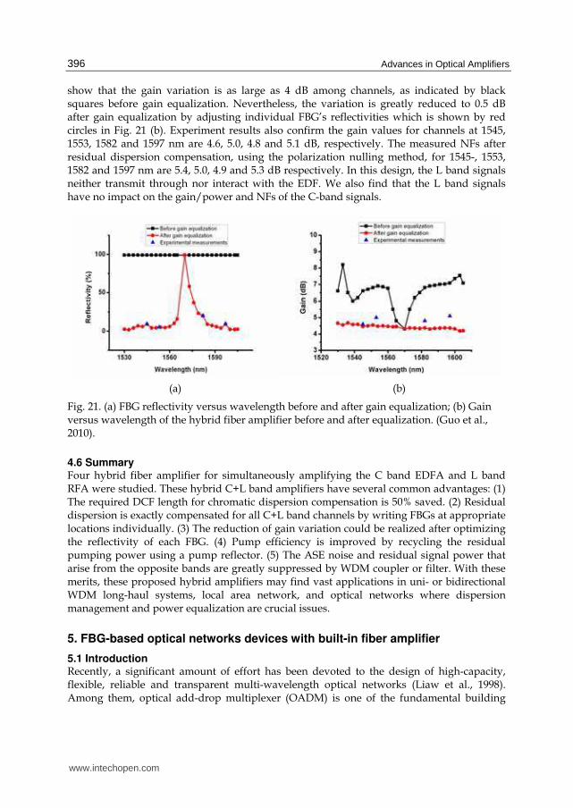
show that the gain variation is as large as 4 dB among channels, as indicated by black squares before gain equalization. Nevertheless, the variation is greatly reduced to 0.5 dB after gain equalization by adjusting individual FBG’s reflectivities which is shown by red circles in Fig. 21 (b). Experiment results also confirm the gain values for channels at 1545, 1553, 1582 and 1597 nm are 4.6, 5.0, 4.8 and 5.1 dB, respectively. The measured NFs after residual dispersion compensation, using the polarization nulling method, for 1545-, 1553, 1582 and 1597 nm are 5.4, 5.0, 4.9 and 5.3 dB respectively. In this design, the L band signals neither transmit through nor interact with the EDF. We also find that the L band signals have no impact on the gain/power and NFs of the C-band signals.
(a) (b)
Fig. 21. (a) FBG reflectivity versus wavelength before and after gain equalization; (b) Gain versus wavelength of the hybrid fiber amplifier before and after equalization. (Guo et al., 2010).
4.6 Summary Four hybrid fiber amplifier for simultaneously amplifying the C band EDFA and L band RFA were studied. These hybrid C+L band amplifiers have several common advantages: (1) The required DCF length for chromatic dispersion compensation is 50% saved. (2) Residual dispersion is exactly compensated for all C+L band channels by writing FBGs at appropriate locations individually. (3) The reduction of gain variation could be realized after optimizing the reflectivity of each FBG. (4) Pump efficiency is improved by recycling the residual pumping power using a pump reflector. (5) The ASE noise and residual signal power that arise from the opposite bands are greatly suppressed by WDM coupler or filter. With these merits, these proposed hybrid amplifiers may find vast applications in uni- or bidirectional WDM long-haul systems, local area network, and optical networks where dispersion management and power equalization are crucial issues.
5. FBG-based optical networks devices with built-in fiber amplifier
5.1 Introduction Recently, a significant amount of effort has been devoted to the design of high-capacity, flexible, reliable and transparent multi-wavelength optical networks (Liaw et al., 1998). Among them, optical add-drop multiplexer (OADM) is one of the fundamental building
www.intechopen.com
Fiber-Bragg-Grating Based Optical Amplifiers
397
blocks for a multi-wavelength optical network (Riziotis et al., 2002), such as the dense wavelength-division-multiplexing (WDM) system and optical networks. A reconfigurable OADM (ROADM) is capable of accessing all wavelengths to and from the WDM optical networks, providing the network flexibility, versatility, survivability (Liaw et al., 1998). Compared to unidirectional transmission, bidirectional transmission has the merit of 50% cost reduction for optical fibers and the required number of passive fiber components may therefore be reduced. In optical networks, an optical cross-connect (OXC) device is also an essential equipment for wavelength exchanging and routing. It allows the optical network to be reconfigured on a wavelength-by-wavelength basis to interchange and optimize traffic patterns, and provides the routing function, facilitate network growth, and enhance network survivability (Brackett et al., 1996). FBGs have the advantages of better uniformity, high contrast ratio and low cost. Hence, FBG-based unidirectional ROADM, bidirectional ROADM were investigated, with a low-cost optical amplifier acts as a gain provider in both cases. In addition, an FBG-based OXC integrated with optical limiting amplifiers (OLA’s) to provide a large dynamic range and self-equalization is also introduced in this section.
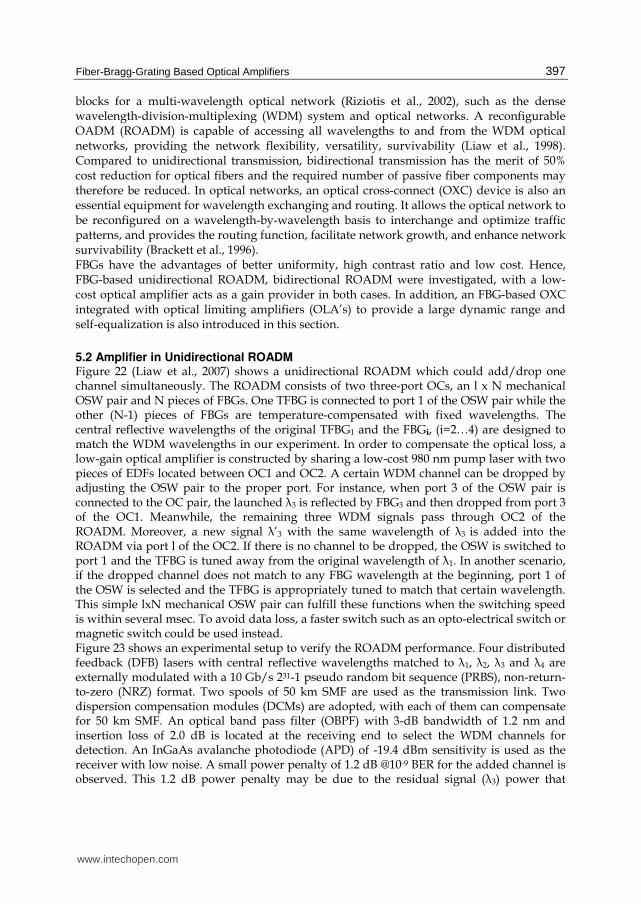
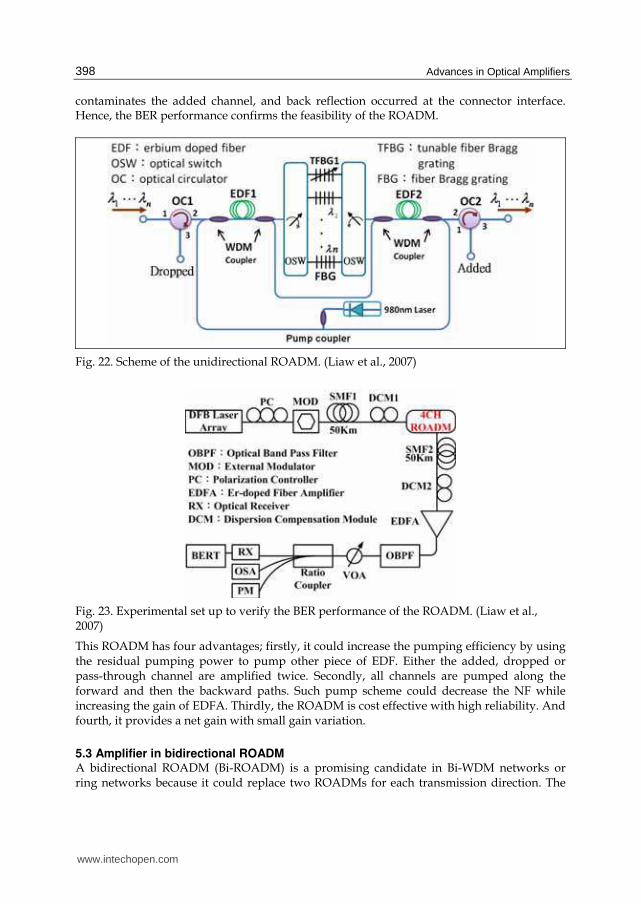
5.2 Amplifier in Unidirectional ROADM Figure 22 (Liaw et al., 2007) shows a unidirectional ROADM which could add/drop one channel simultaneously. The ROADM consists of two three-port OCs, an l x N mechanical OSW pair and N pieces of FBGs. One TFBG is connected to port 1 of the OSW pair while the other (N-1) pieces of FBGs are temperature-compensated with fixed wavelengths. The central reflective wavelengths of the original TFBG1 and the FBGi, (i=2…4) are designed to match the WDM wavelengths in our experiment. In order to compensate the optical loss, a low-gain optical amplifier is constructed by sharing a low-cost 980 nm pump laser with two pieces of EDFs located between OC1 and OC2. A certain WDM channel can be dropped by adjusting the OSW pair to the proper port. For instance, when port 3 of the OSW pair is connected to the OC pair, the launched ┣3 is reflected by FBG3 and then dropped from port 3 of the OC1. Meanwhile, the remaining three WDM signals pass through OC2 of the ROADM. Moreover, a new signal ┣’3 with the same wavelength of ┣3 is added into the ROADM via port l of the OC2. If there is no channel to be dropped, the OSW is switched to port 1 and the TFBG is tuned away from the original wavelength of ┣1. In another scenario, if the dropped channel does not match to any FBG wavelength at the beginning, port 1 of the OSW is selected and the TFBG is appropriately tuned to match that certain wavelength. This simple lxN mechanical OSW pair can fulfill these functions when the switching speed is within several msec. To avoid data loss, a faster switch such as an opto-electrical switch or magnetic switch could be used instead. Figure 23 shows an experimental setup to verify the ROADM performance. Four distributed feedback (DFB) lasers with central reflective wavelengths matched to ┣1, ┣2, ┣3 and ┣4 are externally modulated with a 10 Gb/s 231-1 pseudo random bit sequence (PRBS), non-return-to-zero (NRZ) format. Two spools of 50 km SMF are used as the transmission link. Two dispersion compensation modules (DCMs) are adopted, with each of them can compensate for 50 km SMF. An optical band pass filter (OBPF) with 3-dB bandwidth of 1.2 nm and insertion loss of 2.0 dB is located at the receiving end to select the WDM channels for detection. An InGaAs avalanche photodiode (APD) of -19.4 dBm sensitivity is used as the receiver with low noise. A small power penalty of 1.2 dB @10-9 BER for the added channel is observed. This 1.2 dB power penalty may be due to the residual signal (┣3) power that
www.intechopen.com
Advances in Optical Amplifiers
398
contaminates the added channel, and back reflection occurred at the connector interface. Hence, the BER performance confirms the feasibility of the ROADM.
Fig. 22. Scheme of the unidirectional ROADM. (Liaw et al., 2007)
Fig. 23. Experimental set up to verify the BER performance of the ROADM. (Liaw et al., 2007)
This ROADM has four advantages; firstly, it could increase the pumping efficiency by using the residual pumping power to pump other piece of EDF. Either the added, dropped or pass-through channel are amplified twice. Secondly, all channels are pumped along the forward and then the backward paths. Such pump scheme could decrease the NF while increasing the gain of EDFA. Thirdly, the ROADM is cost effective with high reliability. And fourth, it provides a net gain with small gain variation.
5.3 Amplifier in bidirectional ROADM A bidirectional ROADM (Bi-ROADM) is a promising candidate in Bi-WDM networks or ring networks because it could replace two ROADMs for each transmission direction. The
www.intechopen.com
Fiber-Bragg-Grating Based Optical Amplifiers
399
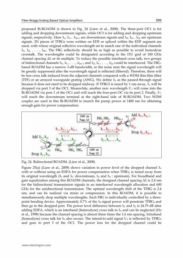
proposed Bi-ROADM is shown in Fig. 24 (Liaw et al., 2008). The three-port OC1 is for adding and dropping downstream signals, while OC3 is for adding and dropping upstream signals, respectively. Here ┣1, ┣3... ┣2n-1 are downstream signals and ┣2, ┣4... ┣2n are upstream signals. 2N pieces of TFBGs were written on EDF or spliced within the EDF segment are used, with whose original reflective wavelength set to match one of the individual channels ┣1, ┣2, . . . , ┣2n. The FBG reflectivity should be as high as possible to avoid homodyne crosstalk. The wavelengths could be designated according to the ITU grid of 100 GHz channel spacing Δ┣ or its multiple. To reduce the possible interband cross talk, two groups of bidirectional channels ┣1, ┣3 , . . . , ┣2n−1 and ┣2, ┣4 , . . . , ┣2n could be interleaved. The FBG-based ROADM has a narrow 3-dB bandwidth, so the noise near the signal wavelength will be greatly suppressed after the wavelength signal is reflected (filtered). Therefore, there will be less cross talk induced from the adjacent channels compared with a WDM thin-film filter (TFF) or an arrayed waveguide grating (AWG). We define ┣3 as the passed-through signal because it does not need to be dropped midway. If TFBG3 is tuned by 1 nm away, ┣1 will be dropped via port 3 of the OC1. Meanwhile, another new wavelength ┣’1 will come into the Bi-ROADM via port 1 of the OC1 and will reach the four-port OC via its port 2. Finally, ┣’1 will reach the downstream terminal at the right-hand side of Bi-ROADM. Two WDM coupler are used in this Bi-ROADM to launch the pump power at 1480 nm for obtaining enough gain for power compensation.
Fig. 24. Bidirectional ROADM. (Liaw et al., 2008)
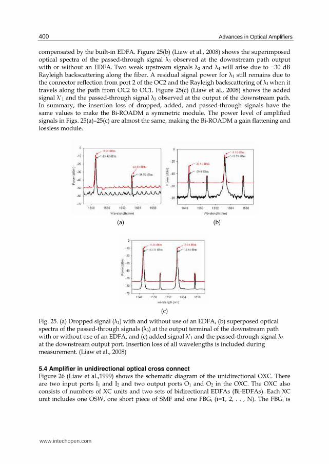
Figure 25(a) (Liaw et al., 2008) shows variation in power level of the dropped channel ┣1 with or without using an EDFA for power compensation when TFBG1 is tuned away from its original wavelength (┣1 and ┣3 :downstream, ┣2 and ┣4 : upstream). For broadband and gain equalization among this ROADM channels, the designed channel spacing Δ┣ is 2.4 nm for the bidirectional transmission signals in an interleaved wavelength allocation and 600 GHz for the unidirectional transmission. The optimal wavelength shift of the TFBG is 2.4 nm, and can be realized via strain or compression. In this ROADM, it is possible to simultaneously drop multiple wavelengths. Each FBG is individually controlled by a three-point bending device. Approximately 0.7% of the ┣3 signal power will penetrate TFBG3 and then go to the dropped port. The power level difference between ┣1 and ┣3 is 24.79 dB after adding EDFA, which is an interband (heterodyne) cross talk to ┣1 and can be neglected (Ho et al., 1998) because the channel spacing is almost three times the 1.6 nm spacing. Intraband (homodyne) cross talk for ┣3 also occurs. The intend-to-add signal ┣’3 is reflected by TFBG3 and goes to port 3 of the OC1. The power loss for the dropped channel could be
www.intechopen.com
Advances in Optical Amplifiers
400
compensated by the built-in EDFA. Figure 25(b) (Liaw et al., 2008) shows the superimposed optical spectra of the passed-through signal ┣3 observed at the downstream path output with or without an EDFA. Two weak upstream signals ┣2 and ┣4 will arise due to −30 dB Rayleigh backscattering along the fiber. A residual signal power for ┣1 still remains due to the connector reflection from port 2 of the OC2 and the Rayleigh backscattering of ┣1 when it travels along the path from OC2 to OC1. Figure 25(c) (Liaw et al., 2008) shows the added signal ┣’1 and the passed-through signal ┣3 observed at the output of the downstream path. In summary, the insertion loss of dropped, added, and passed-through signals have the same values to make the Bi-ROADM a symmetric module. The power level of amplified signals in Figs. 25(a)–25(c) are almost the same, making the Bi-ROADM a gain flattening and lossless module.
(a) (b)
(c)
Fig. 25. (a) Dropped signal (┣1) with and without use of an EDFA, (b) superposed optical spectra of the passed-through signals (┣3) at the output terminal of the downstream path with or without use of an EDFA, and (c) added signal ┣’1 and the passed-through signal ┣3
at the downstream output port. Insertion loss of all wavelengths is included during measurement. (Liaw et al., 2008)
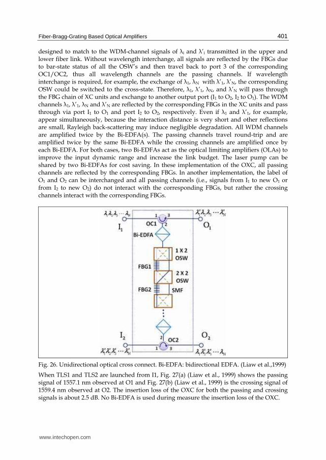
5.4 Amplifier in unidirectional optical cross connect Figure 26 (Liaw et al.,1999) shows the schematic diagram of the unidirectional OXC. There are two input ports I1 and I2 and two output ports O1 and O2 in the OXC. The OXC also consists of numbers of XC units and two sets of bidirectional EDFAs (Bi-EDFAs). Each XC unit includes one OSW, one short piece of SMF and one FBGi (i=1, 2, . . , N). The FBGi is
www.intechopen.com
Fiber-Bragg-Grating Based Optical Amplifiers
401
designed to match to the WDM-channel signals of ┣i and ┣’i transmitted in the upper and lower fiber link. Without wavelength interchange, all signals are reflected by the FBGs due to bar-state status of all the OSW’s and then travel back to port 3 of the corresponding OC1/OC2, thus all wavelength channels are the passing channels. If wavelength interchange is required, for example, the exchange of ┣1, ┣N with ┣’1, ┣’N, the corresponding OSW could be switched to the cross-state. Therefore, ┣1, ┣’1, ┣N, and ┣’N will pass through the FBG chain of XC units and exchange to another output port (I1 to O2, I2 to O1). The WDM channels ┣1, ┣’1, ┣N and ┣’N are reflected by the corresponding FBGs in the XC units and pass through via port I1 to O1 and port I2 to O2, respectively. Even if ┣1 and ┣’1, for example, appear simultaneously, because the interaction distance is very short and other reflections are small, Rayleigh back-scattering may induce negligible degradation. All WDM channels are amplified twice by the Bi-EDFA(s). The passing channels travel round-trip and are amplified twice by the same Bi-EDFA while the crossing channels are amplified once by each Bi-EDFA. For both cases, two Bi-EDFAs act as the optical limiting amplifiers (OLAs) to improve the input dynamic range and increase the link budget. The laser pump can be shared by two Bi-EDFAs for cost saving. In these implementation of the OXC, all passing channels are reflected by the corresponding FBGs. In another implementation, the label of O1 and O2 can be interchanged and all passing channels (i.e., signals from I1 to new O1 or from I2 to new O2) do not interact with the corresponding FBGs, but rather the crossing channels interact with the corresponding FBGs.
Fig. 26. Unidirectional optical cross connect. Bi-EDFA: bidirectional EDFA. (Liaw et al.,1999)
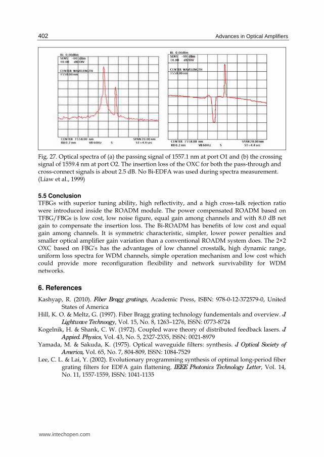
When TLS1 and TLS2 are launched from I1, Fig. 27(a) (Liaw et al., 1999) shows the passing signal of 1557.1 nm observed at O1 and Fig. 27(b) (Liaw et al., 1999) is the crossing signal of 1559.4 nm observed at O2. The insertion loss of the OXC for both the passing and crossing signals is about 2.5 dB. No Bi-EDFA is used during measure the insertion loss of the OXC.
www.intechopen.com
Advances in Optical Amplifiers
402
Fig. 27. Optical spectra of (a) the passing signal of 1557.1 nm at port O1 and (b) the crossing signal of 1559.4 nm at port O2. The insertion loss of the OXC for both the pass-through and cross-connect signals is about 2.5 dB. No Bi-EDFA was used during spectra measurement. (Liaw et al., 1999)
5.5 Conclusion TFBGs with superior tuning ability, high reflectivity, and a high cross-talk rejection ratio were introduced inside the ROADM module. The power compensated ROADM based on TFBG/FBGs is low cost, low noise figure, equal gain among channels and with 8.0 dB net gain to compensate the insertion loss. The Bi-ROADM has benefits of low cost and equal gain among channels. It is symmetric characteristic, simpler, lower power penalties and smaller optical amplifier gain variation than a conventional ROADM system does. The 2×2 OXC based on FBG‘s has the advantages of low channel crosstalk, high dynamic range, uniform loss spectra for WDM channels, simple operation mechanism and low cost which could provide more reconfiguration flexibility and network survivability for WDM networks.
6. References
Kashyap, R. (2010). Fiber Bragg gratings, Academic Press, ISBN: 978-0-12-372579-0, United States of America
Hill, K. O. & Meltz, G. (1997). Fiber Bragg grating technology fundementals and overview. J. Lightwave Technoogy, Vol. 15, No. 8, 1263–1276, ISSN: 0773-8724
Kogelnik, H. & Shank, C. W. (1972). Coupled wave theory of distributed feedback lasers. J. Appied. Physics, Vol. 43, No. 5, 2327-2335, ISSN: 0021-8979
Yamada, M. & Sakuda, K. (1975). Optical waveguide filters: synthesis. J. Optical Society of
America, Vol. 65, No. 7, 804-809, ISSN: 1084-7529 Lee, C. L. & Lai, Y. (2002). Evolutionary programming synthesis of optimal long-period fiber
grating filters for EDFA gain flattening. IEEE Photonics Technology Letter, Vol. 14, No. 11, 1557-1559, ISSN: 1041-1135
www.intechopen.com
Fiber-Bragg-Grating Based Optical Amplifiers
403
Chuang, K. P.; Sheu, L. G. & Lai, Y. (2004). Complex fiber grating structures fabricated by sequential writing with polarization control. Optics Letters, Vol. 29, No. 4, 340-342, ISSN: 1539-4794
Hsu, K. C.; Sheu, L. G.; Chuang, K. P.; Chang, S. H. & Lai, Y. (2005). Fiber Bragg grating sequential UV-writing method with real-time interferometric side-diffraction position monitoring. Optics Express, Vol. 13, No. 10, 3795-3801, ISSN: 1094-4087
Qiu, T.; Suzuki, S.; Schülzgen, A.; Li, L.; Polynkin, A.; Temyanko, V.; Moloney, J. V. &
Peyghambarian, N. (2005). Generation of watt-level single-longitudinal-mode output from cladding-pumped short fiber lasers. Optics Letters, Vol. 30, No. 20, 2748-2750, ISSN: 1539-4794
Archambault, J.-L. & Grubb, S. G. (1997). Fiber gratings in lasers and amplifiers. J. Lightwave
Technology, Vol. 15, No. 8, 1378–1390, ISSN: 0933-8724 Liaw, S.-K. & Jhong, G. S. (2008). Tunable fiber laser using a broadband fiber mirror and a
tunable FBG as laser-cavity ends. IEEE J. Quantum Electronics, Vol. 44, No. 6, 520-527, ISSN: 0018-9197
Vengsarkar, A. M.; Pedrazzani, J. R.; Judkins, J. B.; Lemaire, P. J.; Bergano, N. S. & Davidson, C. R. (1996). Long-period fiber-grating-based gain equalizers. Optics Letters, Vol. 21, 336–338, ISSN: 1539-4794
Shehadeh, F.; Vodhanel, R. S;. Krain, M.; Gibbons, C.; Wagner, R. E. & Ali, M. (1995). Gain-equalized, eight-wavelength WDM optical add-drop multiplexer with an 8-dB dynamic range. IEEE Photonic Technology Letters, Vol. 7, 1075–1077, ISSN: 1041-1135
Kim, H. S.; Yun, S. H.; Kim, H. K.; Park, N. & Kim, B. Y. (1998); Actively gain-flattened erbium-doped fiber amplifier over 35 nm by using all-fiber acoustooptic tunable filters. IEEE Photonic Technology Letters, Vol. 10, 790–792, ISSN: 1041-1135
Liaw, S.-K.; Ho, K.-P. & Chi, S. (1999). Dynamic power-equalized EDFA module based on strain tunable fiber Bragg gratings. IEEE Photonic Technology Letters, Vol. 11, 797–799, ISSN: 1041-1135
Hill, K. O.; Bilodeau, F., Malo, B.; Kitagawa, T.; Thériault, S.; Johnson, D. C.; Albert, J. & Takiguchi, K. (1994). Chirped in-fiber Bragg gratings for compensation of optical-fiber dispersion. Optics Letters, Vol. 19, 1314–1316, ISSN: 1539-4794
Pastor, D.; Capmany, J.; Ortega, D.; Tatay, V. & Marti, J. (1996). Design of apodized linearly chirped fiber gratings for dispersion compensation. IEEE Journal of Lightwave
Technology, Vol. 14, 2581–2588, ISSN: 0933-8724 Loh, W. H.; Laming, R. I.; Ellis, A. D. & Atkinson, D. (1996). 10 Gb/s transmission over 700
km of standard single-mode fiber with 10-cm chirped fiber grating compensator and duobinary transmitter. IEEE Photonic Technology Letters, Vol. 8, 1258–1260, ISSN: 1041-1135
Garrett, L. D.; Gnauck, A. H.; Forghieri, F.; Gusmeroli, V. & Scarano, D. (1998). 16x10 Gb/s WDM transmission over 840 km SMF using eleven broadband chirped fiber gratings. ECOC’98, pp. 267–268, Madrid, Spain, September 1998.
Giles, C. R. (1997). Lightwave applications of fiber Bragg gratings. IEEE Journal of Lightwave
Technology, Vol. 15, 1391–1404, ISSN: 1041-1135 Tang, M. & Shum, P. (2003). Design of double-pass discrete Raman amplifier and the
impairments induced by Rayleigh backscattering. Optics Express, Vol. 11, 1887–1893, ISSN: 1094-4087
www.intechopen.com
Advances in Optical Amplifiers
404
Jiang, S.; Bristiel, B.; Jaouën, Y.; Gallion , P.; Pincemin, E. & Capouilliet, S. (2007). Full characterization of modern transmission fibers for Raman amplified-based communication systems. Optical Express, Vol. 15, 4883-4892, ISSN: 1094-4087
Curri, C.V. & Poggiolini, P. (2001). On the optimization of the hybrid Raman/Erbium-doped fiber amplifiers. IEEE Photonics Technology Letter. Vol. 13, 1170-1172, ISSN: 1041-1135
Liaw, S.-K. & Huang, Y.-S. (2008). C +L-band hybrid amplifier using FBGs for dispersion compensation and power equalization. Electronic Letters, Vol. 44, 844-845, ISSN: 003-5194
Liaw, S.-K.; Dou, L.; Xu, A. & Huang, Y.-S. (2009). Optimally gain-flattened and dispersion-managed C + L-band hybrid amplifier using a single-wavelength pump laser. Optics Communications, Vol. 282, 4087-4090 ISSN: 0030-4018
Liaw, S.-K.; Huang, Y.-S.; Hung, H.-K.; Chen, N.-K.; Hsu, K.-C.; Yu, Y.-L.; Wang, T.; Manshina, A. & Tver’yanovic, Y. (2010). Dispersion management and gain flattened for a bridge-type hybrid amplifiers in a pumping recycling mechanism. FOAN
workshop, ICUMT 2010.
Zhou, X., Lu; Shum, P.P. & Cheng, T.-H. (2001). A simplified model and optimal design of a multiwavelength backward-pumped fiber Raman amplifier. IEEE Photonics
Technology Letters, Vol. 13, 945–947, ISSN: 1041-1135 Guo, M.-N.; Liaw, S.-K.; Shum, P.-P.; Chen, N.-K.; Hung, H.-K. & Lin, C. (2011). Single-
wavelength-pump-based bi-directional hybrid fiber amplifier for bi-directional local area network application. Optics Communications, vol. 284, 573–578
Agrawal, G. P. (1995). Nonlinear Fiber Optics, 2nd ed. Academic, ISBN: 978-0-12-369516-1, New York
Liaw, S.-K.; Dou, L. & Xu, A. (2007). Fiber-Bragg-gratings–based dispersion-compensated and gain-flattened Raman fiber amplifier. Optics Express, Vol. 19, 12356-12361, ISSN: 1094-4087
Liaw, S.-K.; Ho, K.-P. & Chi, S. (1998). Multichannel add/drop and cross connect using fiber Bragg gratings and optical switches. Electronics Letters, Vol. 34, 1601–1602, ISSN: 003-5194
Riziotis, C. & Zervas, M.-N. (2002). Performance comparison of Bragg grating-based optical add-drop multiplexers in WDM transmission systems. Circuits, Devices and Systems, IEE Proceedings, Vol. 149, 179-186, ISSN: 1751-9683
Brackett, C.–A. (1996). Foreward— Is there an emerging consensus on WDM networking. J. Lightwave Technoogy, Vol. 14, 936-941, ISSN: 0773-8724
Liaw, S.-K.; Wang, C.-J.; Chen, S.-H. & Lin, Y.-T. (2007). Reconfigurable optical add/drop multiplexer with 8.0 dB net gain using dual-pass amplified scheme. IEICE
Transactions on Communications, Vol. 8, 2016-2021, ISSN: 1745-1345 Liaw, S.-K.; Hsieh, Y.-S.; Cheng, W.-L.; Chang C.-L. & Ting, H.-F. (2008). Bi-directional
reconfigurable optical add/drop multiplexer with power compensated using built-in optical amplifiers. OSA Journal of Optical Networking, Vol. 7, 622-671
Ho, K.-P.; Chan, C.-K.; Tong, F. & Chen, L.-K. (1998). Exact analysis of homodyne crosstalk induced penalty in WDM networks. IEEE Photon Technology Letters, Vol. 10, 457–458, ISSN: 1041-1135
www.intechopen.com
Advances in Optical AmplifiersEdited by Prof. Paul Urquhart
ISBN 978-953-307-186-2Hard cover, 436 pagesPublisher InTechPublished online 14, February, 2011Published in print edition February, 2011
InTech EuropeUniversity Campus STeP Ri Slavka Krautzeka 83/A 51000 Rijeka, Croatia Phone: +385 (51) 770 447 Fax: +385 (51) 686 166www.intechopen.com
InTech ChinaUnit 405, Office Block, Hotel Equatorial Shanghai No.65, Yan An Road (West), Shanghai, 200040, China
Phone: +86-21-62489820 Fax: +86-21-62489821
Optical amplifiers play a central role in all categories of fibre communications systems and networks. Bycompensating for the losses exerted by the transmission medium and the components through which thesignals pass, they reduce the need for expensive and slow optical-electrical-optical conversion. The photonicgain media, which are normally based on glass- or semiconductor-based waveguides, can amplify many highspeed wavelength division multiplexed channels simultaneously. Recent research has also concentrated onwavelength conversion, switching, demultiplexing in the time domain and other enhanced functions. Advancesin Optical Amplifiers presents up to date results on amplifier performance, along with explanations of theirrelevance, from leading researchers in the field. Its chapters cover amplifiers based on rare earth doped fibresand waveguides, stimulated Raman scattering, nonlinear parametric processes and semiconductor media.Wavelength conversion and other enhanced signal processing functions are also considered in depth. Thisbook is targeted at research, development and design engineers from teams in manufacturing industry,academia and telecommunications service operators.
How to referenceIn order to correctly reference this scholarly work, feel free to copy and paste the following:
Shien-Kuei Liaw, Kuang-Yu Hsu, Kuei-Chu Hsu and Peng-Chun Peng (2011). Fiber Bragg Grating-BasedOptical Amplifiers, Advances in Optical Amplifiers, Prof. Paul Urquhart (Ed.), ISBN: 978-953-307-186-2,InTech, Available from: http://www.intechopen.com/books/advances-in-optical-amplifiers/fiber-bragg-grating-based-optical-amplifiers


![Fiber Bragg Grating Sensors - Optical Sensing · Fiber Bragg Grating Sensors. ... Bragg grating production Commercial phase mask [Ibsen] with central pitch of 1061.27 nm and operating](https://img.pdfslide.us/doc/110x75/5eb72771ad990c1bc0201c29/fiber-bragg-grating-sensors-optical-fiber-bragg-grating-sensors-bragg-grating.jpg)