Embed Size (px)
Citation preview

VOLU-flo/OAM II Outdoor Airflow Measuring System
Application Guide
www.airmonitor.com • 1-800-AIRFLOW

P.O. Box 6358 • Santa Rosa, CA • USA • 1-800-AIRFLOW • www.airmonitor.com • [email protected] II Airflow System Applications Guide 1018 - 01/18 2
INTRODUCTION
Blowing dust and debris, moist air and low flow velocities are just some of the problems commonly associated with outdoor airflow measurement. These conditions can be very challenging when trying to accurately measure the amount of outdoor air entering a building using thermal or Pitot style airflow elements. Air Monitor’s VOLU-flo/OAM II Airflow Measuring System is a complete system specifically designed to provide accurate airflow measurement in challenging outdoor air applications. The OAM II consists of a dedicated transmitter, reference temperature sensor and uni-sensor flow element. This system offers exceptional performance in this difficult but extremely important airflow measurement application.
The OAM II can be configured to operate in four different modes. Each mode offers distinct advantages for some of the most common outdoor airflow applications. This guide presents an overview of airflow inlet types, OAM II operating modes and system components.
What is the airflow inlet type?There are a variety of outdoor airflow inlet types. The most common inlets incorporate architectural louvers or packaged roof top units with single or multiple rain hoods.
Air Monitor’s uni-sensor assembly is used to measure airflow by measuring static pressures on either side of the inlet. The airflow obstruction and resulting pressure drop across the inlet must be at least 0.06 in wc @ 600 FPM face velocity in order meet the minimum requirements of the uni-sensor assembly.
What is the airflow inlet size/geometry?Many systems are large enough or shaped such that they will require multiple uni-sensors connected in parallel to effectively average total airflow through the inlet. Inlets larger than 30 ft2 in area and those with aspect ratios > 6:1 will require multiple sensors. Split inlets may also require multiple sensors.
What is the best OAM II operating mode for my application?The OAM II has four different factory configured operating modes depending on your inlet type. Each mode is optimized for a specific airflow application. A detailed description of each mode is provided on the next page.
Consider the following when selecting an outdoor airflow measuring system:
P.O. Box 6358 • Santa Rosa, CA • USA • 1-800-AIRFLOW • www.airmonitor.com • [email protected] II Airflow System Applications Guide 1018 - 01/18 3
OPERATING MODES AND INLET TYPES
OPERATING MODES
The OAM II can be factory configured to operate in four different modes.
Minimum Airflow Measurement – This mode provides airflow measurement from 100 to 600 FPM, making it ideal for this application.
Extended Airflow Measurement – This mode provides airflow measurement from 100 to 2400 FPM (up to 24:1 turndown). It is ideal for measuring highly variable airflow in a single inlet.
Min / Max (Split) Airflow Measurement – The min/max (split) mode provides combined airflow measurement for separate (6:1 turndown) minimum and economizer inlets. The OAM II is an effective tool for measuring this commonly used inlet configuration.
Dual Inlet Airflow Measurement – The dual operation mode provides two separate (6:1 turndown) airflow measurements in one transmitter. Ideal for built up systems that provide outdoor air to multiple locations.
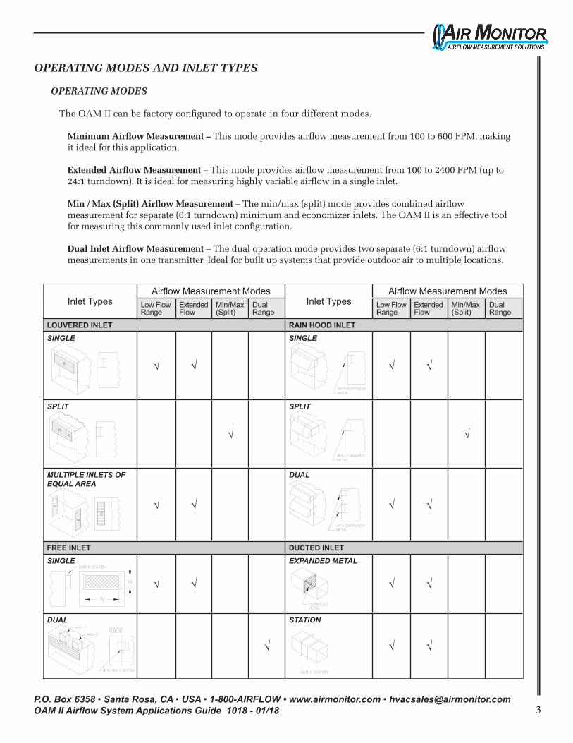
Inlet TypesAirflow Measurement Modes
Inlet TypesAirflow Measurement Modes
Low Flow Range
Extended Flow
Min/Max (Split)
Dual Range
Low Flow Range
Extended Flow
Min/Max (Split)
Dual Range
LOUVERED INLET RAIN HOOD INLETSINGLE
√ √
SINGLE
√ √
SPLIT
√
SPLIT
√
MULTIPLE INLETS OF EQUAL AREA
√ √
DUAL
√ √
FREE INLET DUCTED INLETSINGLE
√ √
EXPANDED METAL
√ √
DUAL
√
STATION
√ √
P.O. Box 6358 • Santa Rosa, CA • USA • 1-800-AIRFLOW • www.airmonitor.com • [email protected] II Airflow System Applications Guide 1018 - 01/18 4
INLET TYPES
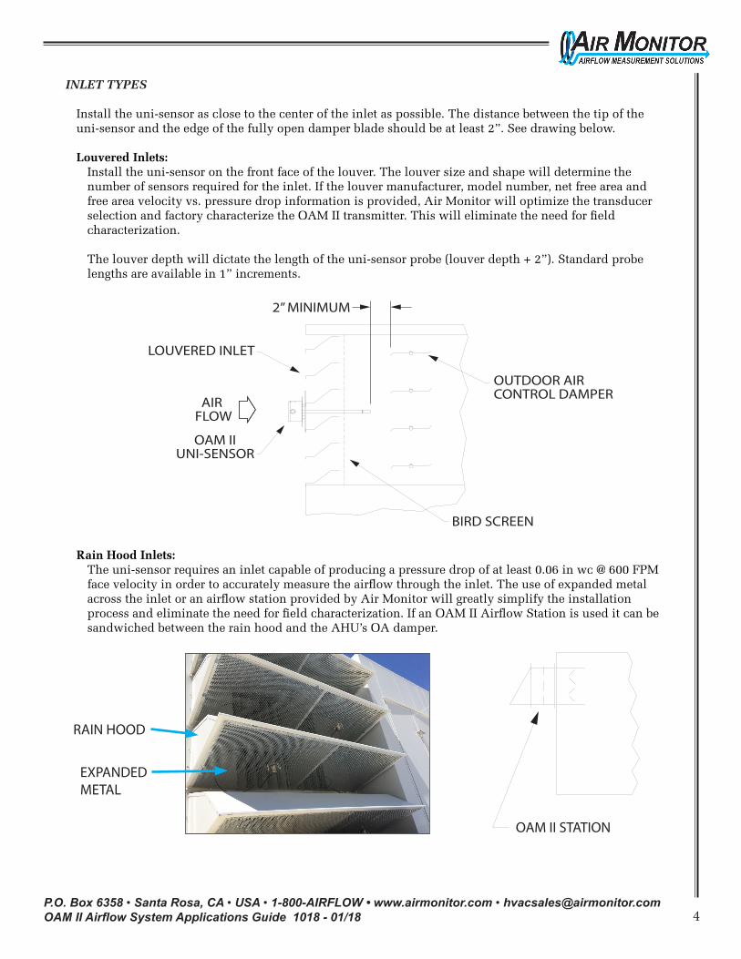
Install the uni-sensor as close to the center of the inlet as possible. The distance between the tip of the uni-sensor and the edge of the fully open damper blade should be at least 2”. See drawing below.
Louvered Inlets: Install the uni-sensor on the front face of the louver. The louver size and shape will determine the number of sensors required for the inlet. If the louver manufacturer, model number, net free area and free area velocity vs. pressure drop information is provided, Air Monitor will optimize the transducer selection and factory characterize the OAM II transmitter. This will eliminate the need for field characterization.
The louver depth will dictate the length of the uni-sensor probe (louver depth + 2”). Standard probe lengths are available in 1” increments.
Rain Hood Inlets: The uni-sensor requires an inlet capable of producing a pressure drop of at least 0.06 in wc @ 600 FPM face velocity in order to accurately measure the airflow through the inlet. The use of expanded metal across the inlet or an airflow station provided by Air Monitor will greatly simplify the installation process and eliminate the need for field characterization. If an OAM II Airflow Station is used it can be sandwiched between the rain hood and the AHU’s OA damper.
RAIN HOOD
EXPANDEDMETAL
OUTDOOR AIR CONTROL DAMPER
AIR FLOW
OAM IIUNI-SENSOR
LOUVERED INLET
BIRD SCREEN
2” MINIMUM
OAM II STATION
P.O. Box 6358 • Santa Rosa, CA • USA • 1-800-AIRFLOW • www.airmonitor.com • [email protected] II Airflow System Applications Guide 1018 - 01/18 5
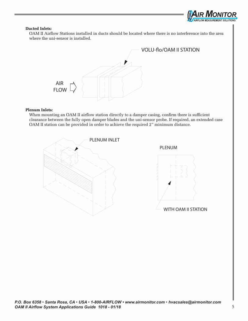
VOLU-�o/OAM II STATION
AIR FLOW
Ducted Inlets: OAM II Airflow Stations installed in ducts should be located where there is no interference into the area where the uni-sensor is installed.
Plenum Inlets: When mounting an OAM II airflow station directly to a damper casing, confirm there is sufficient clearance between the fully open damper blades and the uni-sensor probe. If required, an extended case OAM II station can be provided in order to achieve the required 2” minimum distance.
WITH OAM II STATION
PLENUM
PLENUM INLET
P.O. Box 6358 • Santa Rosa, CA • USA • 1-800-AIRFLOW • www.airmonitor.com • [email protected] II Airflow System Applications Guide 1018 - 01/18 6
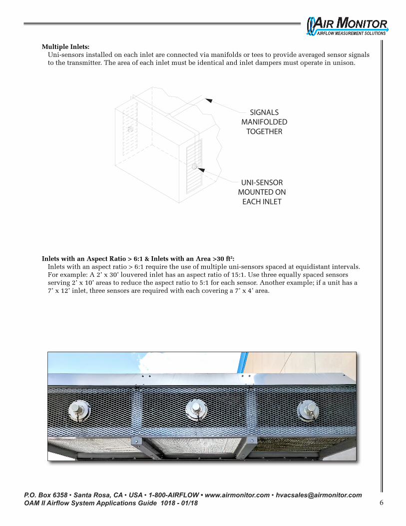
Multiple Inlets: Uni-sensors installed on each inlet are connected via manifolds or tees to provide averaged sensor signals to the transmitter. The area of each inlet must be identical and inlet dampers must operate in unison.
Inlets with an Aspect Ratio > 6:1 & Inlets with an Area >30 ft2: Inlets with an aspect ratio > 6:1 require the use of multiple uni-sensors spaced at equidistant intervals. For example: A 2’ x 30’ louvered inlet has an aspect ratio of 15:1. Use three equally spaced sensors serving 2’ x 10’ areas to reduce the aspect ratio to 5:1 for each sensor. Another example; if a unit has a 7’ x 12’ inlet, three sensors are required with each covering a 7’ x 4’ area.
UNI-SENSORMOUNTED ON
EACH INLET
SIGNALSMANIFOLDED
TOGETHER
P.O. Box 6358 • Santa Rosa, CA • USA • 1-800-AIRFLOW • www.airmonitor.com • [email protected] II Airflow System Applications Guide 1018 - 01/18 7
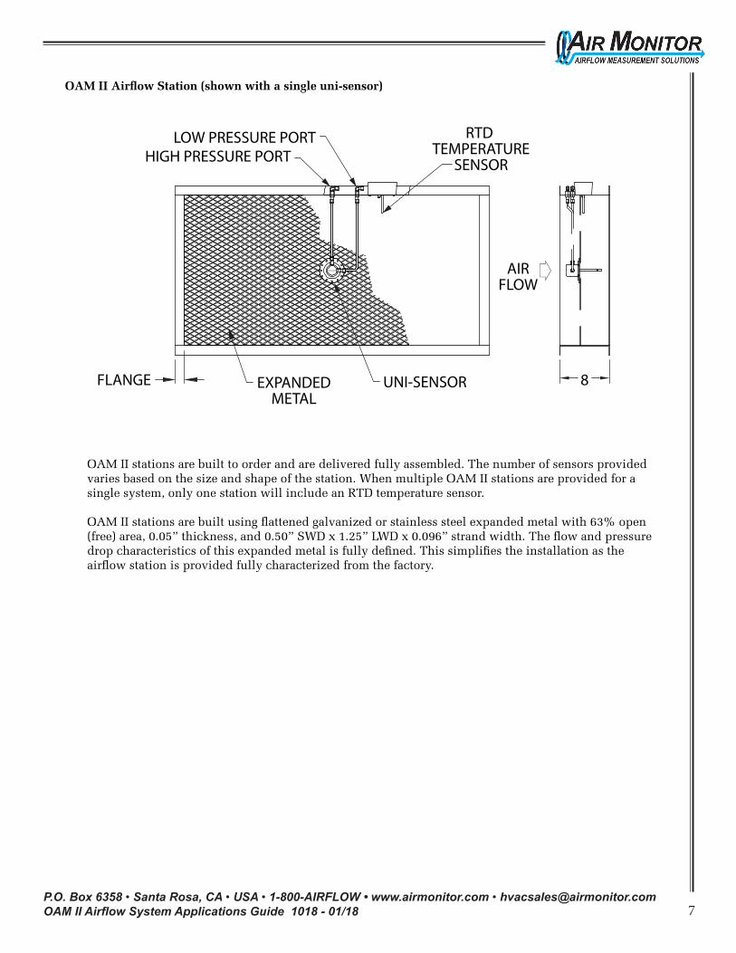
OAM II Airflow Station (shown with a single uni-sensor)
OUTSIDE AIR MONITORVOLU-flo/OAM ll
OAM II Airflow Station
LOW PRESSURE PORTHIGH PRESSURE PORT
FLANGE
AIRFLOW
8EXPANDEDMETAL
UNI-SENSOR
RTD TEMPERATURE
SENSOR
OAM II stations are built to order and are delivered fully assembled. The number of sensors provided varies based on the size and shape of the station. When multiple OAM II stations are provided for a single system, only one station will include an RTD temperature sensor.
OAM II stations are built using flattened galvanized or stainless steel expanded metal with 63% open (free) area, 0.05” thickness, and 0.50” SWD x 1.25” LWD x 0.096” strand width. The flow and pressure drop characteristics of this expanded metal is fully defined. This simplifies the installation as the airflow station is provided fully characterized from the factory.
P.O. Box 6358 • Santa Rosa, CA • USA • 1-800-AIRFLOW • www.airmonitor.com • [email protected] II Airflow System Applications Guide 1018 - 01/18 8
AIRFLOW SENSORS
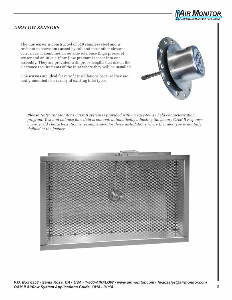
The uni-sensor is constructed of 316 stainless steel and is resistant to corrosion caused by salt and most other airborne corrosives. It combines an outside reference (high pressure) sensor and an inlet airflow (low pressure) sensor into one assembly. They are provided with probe lengths that match the clearance requirements of the inlet where they will be installed.
Uni-sensors are ideal for retrofit installations because they are easily mounted to a variety of existing inlet types.
Please Note: Air Monitor’s OAM II system is provided with an easy-to-use field characterization program. Test and balance flow data is entered, automatically adjusting the factory OAM II response curve. Field characterization is recommended for those installations where the inlet type is not fully defined at the factory.