Embed Size (px)
Citation preview
Journal of ELECTRICAL ENGINEERING, VOL. 53, NO. 5-6, 2002, 132–137
VOLTERRA FILTER APPLICATION INDS–SS RECEIVER FOR BROADBAND AND
NARROWBAND INTERFERENCE SUPPRESSION
Dusan Kocur — Rudolf Zetık — Pavol Galajda∗
Direct sequence spread spectrum (DS-SS) transmission systems offer a promising solution to an overcrowded frequency
spectrum amid the growing demand for mobile and personal communication service. The overlay of DS-SS signals on the
existing broadbands and narrowbands implies strong interference for DS-SS systems. In this paper, it will be shown how the
application of linear or non-linear estimators in DS-SS receivers can suppress this interference. In our consideration, Wiener
filters (WF) and Volterra filters (VF) will be used as estimators. In order to demonstrate the ability of the discussed DS-SS
receivers to suppress interference, a number of computer experiments will be done. The results of these experiments will
show that the application of VF in DS-SS receivers can outperform the DS-SS receivers based on simple application of the
matched filter (MF) or on the WF application in a significant way.
K e y w o r d s: DS-SS receiver structures, Volterra filter, Wiener filter, broadband and narrowband interference
1 INTRODUCTION
In modern mobile communication systems, reutiliza-tion of the frequency band already allocated to somefixed broadband communication system is a promisingopportunity. Here, the application of DS-SS transmissionsystems for mobile communication systems offers a verygood solution. The DS-SS systems can share also a com-mon spectrum with a currently operating cellular or fixedmicrowave system in order to achieve efficient bandwidthutilisation. In this case, the signals of coexisting users ap-pear as narrowband interference in the spectrum of DS-SS signals. The DS-SS transmission systems can operatesuccessfully in the presence of the strong co-channel inter-ference (eg in the case of broadband BPSK broadcastingor narrowband interference) if the processing gain is highenough. If the interference due to co-channel transmissionis very strong or if the processing gain is limited due tobandwidth constraints, DS-SS receiver based on a simpleMF usually cannot provide an acceptable bit-error-rate(BER). In order to solve this problem, some advancedstructures of the DS-SS receivers can be applied [1–3].
In this paper, the DS-SS receivers based on linear andnon-linear estimators will be described. In the conven-tional receiver structure the estimator is included betweenthe demodulator and the despreading stage. The estima-tor provides extraction of the demodulated spreaded sig-nal from the noise. Because of signal pre-processing per-formed by the estimator, signal to noise ratio before thesignal despreading operation is higher than that of a con-ventional receiver based on simple MF application. It canresult in an improvement of BER characteristics in asignificant way.
In this paper, WF and VF will be applied as the above-mentioned estimators. In order to demonstrate the per-formance of the properties of VF and WF based DS-SSreceivers, a number of computer experiments have beendone. The main intention of these experiments was toshow the ability of tested DS-SS receivers to suppressbroadband interference represented by BPSK broadcast-ing. The results of experiments, expressed as BER vs
signal to interference ratio (SIR), have shown that inthe case of DS-SS receivers based on the third order VFoutperform DS-SS receivers based on MF, WF or the sec-ond order VF. These results can be considered to be veryinteresting and stimulating. With regard to these facts wehave tested the same DS-SS receivers for narrowband in-terference suppression represented by the second orderautoregressive process. The results obtained here haveshown that DS-SS receivers based on the third order VFalso in this case can provide better results than receiversbased on MF or WF.
2 INPUT SIGNAL MODEL
OF DS–SS RECEIVER
The signal that appears at the input of the receiverconsists of three components. They are the BPSK DS-SSsignal distorted by a linear transmission channel (x(t)),broadband or narrowband interference (i(t)) and additivewhite Gaussian noise (AWGN, n(t)) with power spectraldensity at the receiver input N0 . The AWGN level willbe expressed by ratio Eb/N0 (information signal energyper bit to noise power spectral density). All three signalcomponents are supposed to be independent and station-ary signals. Then, the input signal to the receiver is given
∗Department of Electronics and Multimedia Communications,
∗∗Department of Theoretical Electrotechnics and Measurement,
Faculty of Electrical Engineering and Informatics, Technical University of Kosice, Letna 9, 041 20 Kosice, Slovakia
E-mail: [email protected], [email protected], [email protected]
ISSN 1335-3632 c© 2002 FEI STU

Journal of ELECTRICAL ENGINEERING VOL. 53, NO. 5-6, 2002 133
Integrate& dump
over chipperiod TC
i(t)
x(t)
n(t)cos(w0t) PNS
nTC
Decision
stageåi=1
L
Matched filter
( )nd)
y(t)
Fig. 1. The DS-SS receiver structure based on simple MF
Integrate &dump overchip period
TC
cos(w0t) PNS
nTC
Decisionstage
åi=1
Matched filter
Estimator
i(t)
x(t)
n(t)
v(n)y(t)
( )nd)
w(n) L
Fig. 2. The DS-SS receiver structure based on estimator applica-
tion
by
y(t) = x(t) + i(t) + n(t) . (1)
The BPSK DS-SS signal s(t) can be modelled as
s(t) = U PNS(t) d(t) cos(ω0t) , (2)
where U , ω0 , PNS(t) and d(t) ∈ {+1,−1} representthe amplitude and angular frequency of the carrier, thepseudo-noise sequence (spreading code) of chip durationTC and transmitted information baseband signal of bitduration T , respectively. Then, BPSK DS-SS signal dis-torted by a linear transmission channel with an impulseresponse h(t) is given by
x(t) = h(t) ∗ s(t) , (3)
where ∗ denotes the convolution operation.
The interference i(t) is defined as
i(t) =
{
piB(t) for broadband interference
piN (t) for narrowband interference.(4)
The broadband interference iB(t) is modelled as abroadband BPSK signal expressed as
iB(t) = USdS(t+ τ) cos [(ω0 + 2πf1)t+ θ] , (5)
where US , f1 , τ , dS(t) ∈ {+1,−1} and θ are interfer-ence amplitude, offset carrier frequency, random data bitdelay, interference data and initial carrier phase, respec-tively. It is assumed that τ ∈ 〈0, T 〉 and θ ∈ 〈0, 2π〉 areuniformly distributed.
The narrowband interference iN (t) is modelled by
iN (t) +
p∑
i=1
aiiN (t− i) = e(t) , (6)
where e(t) is a white Gaussian process with variance
σ2e . The process iN (t) generated by the above model is
known as the pth order autoregressive process (AR(p)).In accordance with [4] the power spectrum of iN (t) is
s(ω) = H(ejω)H(e−jω)σ2
e , (7)
where
H(z) =1
1 + a(1)z−1 + a(2)z−2 + · · ·+ a(p)z−p. (8)
The poles of H(z) are located inside the unit circle.
3 DS–SS RECEIVER STRUCTURES
The simplest DS-SS receiver is based on MF filter ap-plication (correlation receiver) [3]. Its structure is illus-trated in Fig. 1. Here, as the MF, L-tap linear FIR filteris applied. Its impulse response is equal to the spread-ing code PNS(t) . It follows from the MF theory thata MF is optimum when the filtered signal is impairedby AWGN. However, this assumption is not valid in thecase of broadband or narrowband interference or in thecase of multi-user interference (eg CDMA communicationsystems). Therefore, the receiver structure based on theMF application (Fig. 1) cannot be considered as optimumgenerally.
In order to improve the receiver performance, the mod-ified structure of DS-SS receivers equipped by an estima-tor can be applied. Figure 2 shows how the estimator fitsinto DS-SS receiver structure. The estimator extracts thedemodulated spreaded signal from the noise. This signalpre-processing operation can improve the signal to noiseratio before signal despreading. It can result in improve-ment of BER characteristics of the receiver in a signifi-cant way. As the estimator a number of conventional oradvanced digital filters can be used. In the next, WF andVF will be proposed for that purpose.
4 VOLTERRA FILTERS, WIENER FILTERS
The VFs are minimum mean-square non-linear esti-mators. Their mathematical model is represented by atruncated discrete Volterra series [5, 6]. The mathemati-
cal model of the M th order VF memory the span of whichis N = N1 + N2 + 1 samples long (VF(M,N)) is givenby
w(n) = h0 +M∑
i=1
N2∑
k1=−N1
N2∑
k2=−N1
· · ·
N2∑
ki=−N1
hi,k1,k2,...,kiv(n− k1)v(n− k2) . . . v(n− ki) . (9)
In this expression, v(n) and w(n) are the input signaland the filter response, respectively. The i -dimensionalsequence hi,k1,k2,...,ki is called the Volterra kernel of the
ith order. The order M of the VF is defined by thenumber of the highest order of the Volterra kernel which
134 D. Kocur — R. Zetık — P. Galajda: VOLTERRA FILTER APPLICATION IN DS-SS RECEIVER FOR BROADBAND AND . . .
-35 -30 -25 -20 -15 -10 -5 0 5 10-25
-20
-15
-10
-5
0
5
10
SIR (dB)
SNR (dB)
VF(3,3),VF(3,5) VF(3,1)
VF(2,3),VF(2,5)WF(5),WF(7),
MF
Fig. 3. SNR vs SIR
-35 -30 -25 -20 -15 -10 -5 0 5 1010
-5
10-4
10-3
10-2
10-1
100
SIR (dB)
BER
VF(3,3)
VF(3,5)
VF(3,1)
VF(2,3),VF(2,5)WF(5),WF(7),
MF
Fig. 4. BER vs SIR
can be found in (9). The length of the VF memory spanis given by the number of mutually different samples ofthe input signal which can be applied in the VF responsecomputation. Under condition that N1 > 0, VF(M,N)is non-causal.
With regard to (9), the well-known WF of the N th
order (WF(N)) can be defined as the first order VF(ie VF(1, N)). The details concerning the design andperformance properties of time-invariant and adaptiveVF and WF can be found eg in [5-7].
5 EXPERIMENTAL RESULTS
In this section, a comparison of performance proper-ties of the BPSK DS-SS receiver based on a simple MF(Fig. 1.) with its modified version that includes estimator(Fig. 2.) is presented.
In all experiments, the transmission model describedin section 2 was used. The parameters of the BPSK DS-SS signal s(t) were U = 1 and ω0 = 2πFS/4, where FS
stands for the sampling frequency. The Gold sequence ofthe 7th order (7 chips) was applied as the pseudo-noisesequence (spreading code) of chip duration TC = 4/FS .The bit duration of information baseband signal was setto T = 28/FS .
The power spectral density of AWGN at the receiverinput was set in such a way as Eb/N0 = 13 dB.
As the channel model, the linear time-invariant systemrepresented by the FIR filter of the 15th order was used.The filter passband was centered at the carrier frequencyω0 and its bandwidth was set to BCH = 1.2BMIN , whereBMIN is the minimum bandwidth for the BPSK DS-SSsignal transmission.
In the case of the estimator based receivers (Fig. 2)time-invariant WF and VF were applied. For their de-sign the methods described in [5–7] were used. In orderto estimate the correlation and crosscorrelation functions(conventional as well as higher-order ones) necessary forthe WF and VF design, the training sequence consistingof 200 information bits was transmitted before each infor-mation date sequence transmission. The original training
sequence was available at the receivers for the purpose offilter design. In all experiments, perfect synchronizationof the BPSK modulator and demodulator and the DS-SSmodulator and MF is assumed.
As the performance indices of the tested DS-SS re-ceivers, BER vs SIR and BER vs Eb/N0 at differentconditions of interference were used. These conditions aswell as the results corresponding to the particular inter-ference signal are described in the next subsection.
5.1 Broadband interference
In the first experiment, the interference i(t) = iB(t)was synchronized with BPSK DS-SS signal. The param-eters of iB(t) were US = 1, f1 = 0, τ = 0 and θ = 0.The bit duration of baseband interference signal was setto TI = TC . Therefore, the BPSK DS-SS signal band-width (BS ) to interference signal bandwidth (BI ) ratiowas BS/BI = 1.
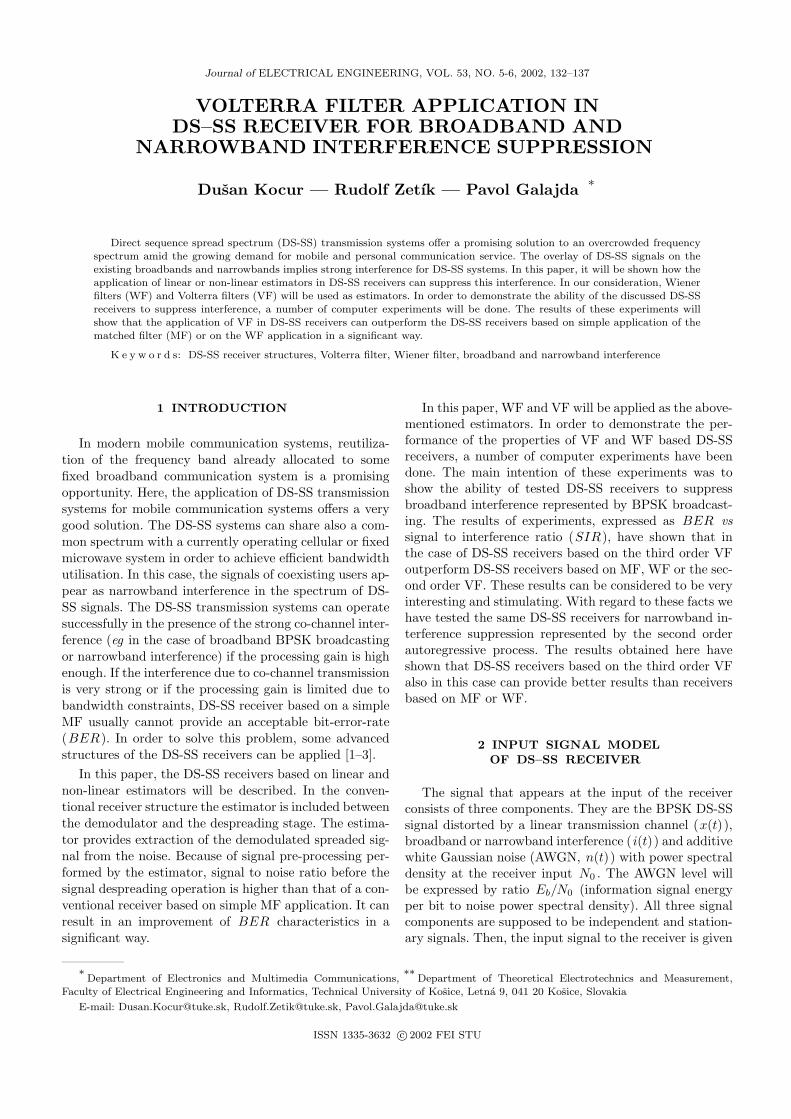
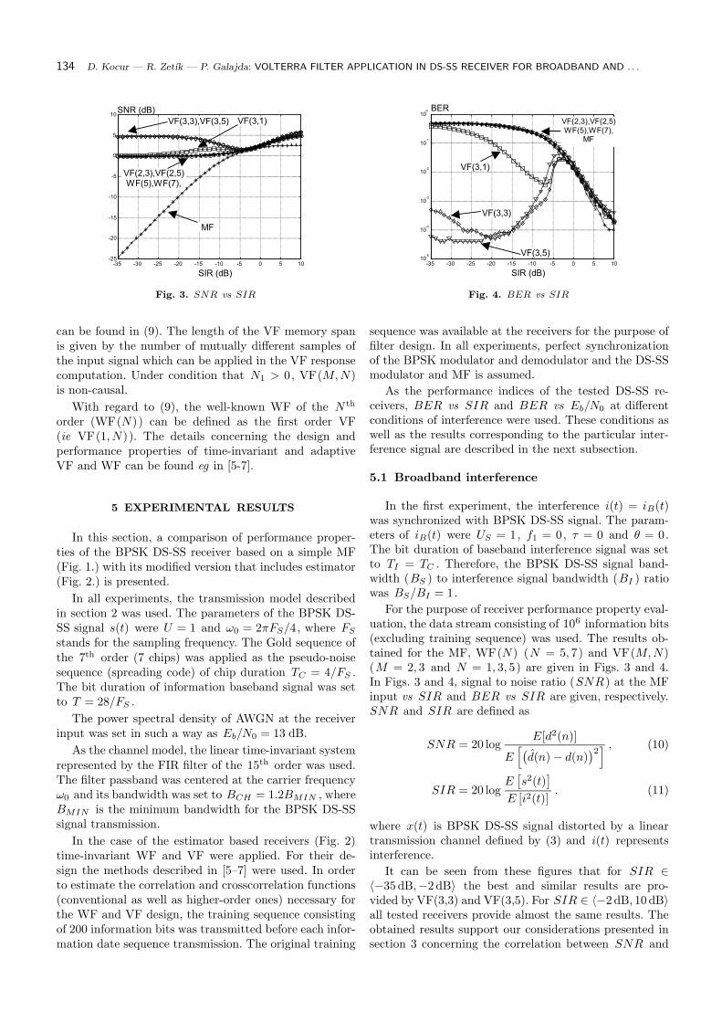
For the purpose of receiver performance property eval-uation, the data stream consisting of 106 information bits(excluding training sequence) was used. The results ob-tained for the MF, WF(N) (N = 5, 7) and VF(M,N)(M = 2, 3 and N = 1, 3, 5) are given in Figs. 3 and 4.In Figs. 3 and 4, signal to noise ratio (SNR) at the MFinput vs SIR and BER vs SIR are given, respectively.SNR and SIR are defined as
SNR = 20 logE[d2(n)]
E[
(
d(n)− d(n))2] , (10)
SIR = 20 logE[
s2(t)]
E [i2(t)]. (11)
where x(t) is BPSK DS-SS signal distorted by a lineartransmission channel defined by (3) and i(t) representsinterference.
It can be seen from these figures that for SIR ∈〈−35 dB,−2 dB〉 the best and similar results are pro-vided by VF(3,3) and VF(3,5). For SIR ∈ 〈−2 dB, 10 dB〉all tested receivers provide almost the same results. Theobtained results support our considerations presented insection 3 concerning the correlation between SNR and
Journal of ELECTRICAL ENGINEERING VOL. 53, NO. 5-6, 2002 135
Norm. spec.
DS-SS signalInterference
f1*F (Hz)s
Fig. 5. Broadband interference — normalized signal spectra in
linear scale
f1*F (Hz)s
DS-SS signal
Interference
Norm. spec.
Fig. 6. Broadband interference — normalized signal spectra in
logarithmical scale
*Fs(H
z)
f 1
BER
SIR (dB)
Fig. 7. Broadband interference — BER vs SIR and f1 , no esti-
mator is applied, Eb/N0 = 13dB
*Fs(H
z)
f 1
BER
SIR (dB)
Fig. 8. Broadband interference — BER vs SIR and f1 , WF(7)
is applied, Eb/N0 = 13dB
*Fs(H
z)
f 1
BER
SIR (dB)
Fig. 9. Broadband interference — BER vs SIR and f1 , VF(3,3)
is applied, Eb/N0 = 13dB
(
(
Fig. 10. Broadband interference - BER vs Eb/N0 and f1 , no
estimator is applied, SIR = −13 dB
BER , too. It can be seen from Fig. 3 that the applica-
tion of VF(3, N) (N = 1, 3, 5) can improve the level of
SNR . Based on this improvement, significantly better re-
sults provided by VF(3, N) are obtained in comparison
with that of the MF, WF(N) and VF(2, N) .
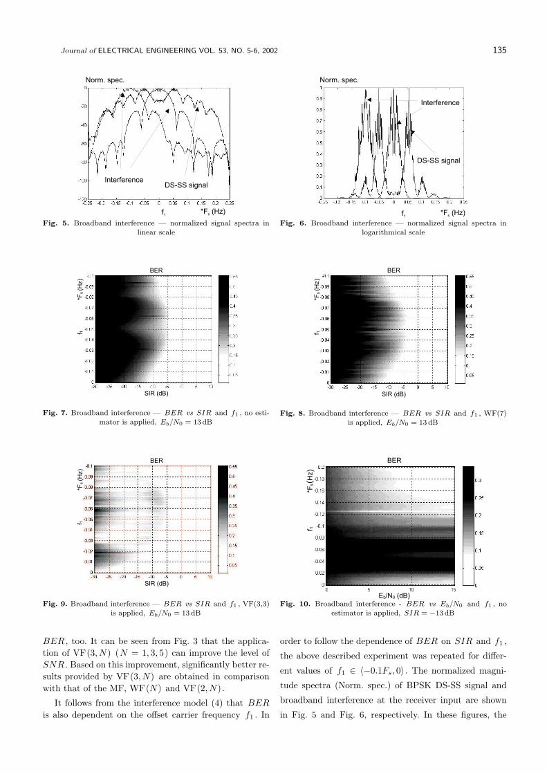
It follows from the interference model (4) that BER
is also dependent on the offset carrier frequency f1 . In
order to follow the dependence of BER on SIR and f1 ,
the above described experiment was repeated for differ-
ent values of f1 ∈ 〈−0.1Fs, 0〉 . The normalized magni-
tude spectra (Norm. spec.) of BPSK DS-SS signal and
broadband interference at the receiver input are shown
in Fig. 5 and Fig. 6, respectively. In these figures, the
136 D. Kocur — R. Zetık — P. Galajda: VOLTERRA FILTER APPLICATION IN DS-SS RECEIVER FOR BROADBAND AND . . .
*Fs(H
z)
f 1BER
Eb/N0 (dB)Fig. 11. Broadband interference — BER vs Eb/N0 and f1 ,
VF(3,3) is applied, SIR = −13 dB
Norm. spec.
f1*F (Hz)s
DS-SS signalInterference
Fig. 12. Narrowband interference — normalized signal spectra in
linear scale
Interference
Norm. spec.
DS-SS signal
f1*F (Hz)s
Fig. 13. Narrowband interference — normalized signal spectra in
logarithmical
*Fs(H
z)
f 1
BER
SIR (dB)
Fig. 14. Narrowband interference — BER vs SIR and f1 , no
estimator is applied, Eb/N0 = 13dB
*Fs(H
z)
f 1
BER
SIR (dB)
Fig. 15. Narrowband interference — BER vs SIR and f1 , WF(7)
is applied, Eb/N0 = 13dB
*Fs(H
z)
f 1
BER
SIR (dB)
Fig. 16. Narrowband interference — BER vs SIR and f1 ,
VF(3,3) is applied, Eb/N0 = 13dB
magnitude spectra of the interference signal are given for
f1 = −0.1FS and f1 = 0.
The results of the second computer experiment are
presented in Figs.7–9. It can be seen from these figures
that also in this case VF(3, 3) can provide much better
results than that of WF(7) or MF.
In order to illustrate additional performance proper-
ties of the VF(3,3), the third experiment was done. The
intention of the experiment was to follow the BER de-pendence on Eb/N0 and f1 ∈ 〈−0.2FS , 0〉 at SIR =−13 dB. The experiment was arranged in a similar wayas the first and the second experiments described in thissection. The results of the experiment are given in Figs.10and 11. It follows from these figures that VF(3,3) is ableto provide meaningful improvement in BER characteris-tics also for different values of Eb/N0 comparing to MFapplication.
Journal of ELECTRICAL ENGINEERING VOL. 53, NO. 5-6, 2002 137
5.2 Narrowband Interference
In the experiment illustrating the narrowband interfer-ence suppression, the interference i(t) = iN (t) was set tothe AR(2) defined by (6)–(8). The magnitudes of complexconjugated poles p1 and p2 of H(z) were set to 0.99. Thearguments p1 and p2 were set in such a way that the cen-tral frequency of the narrowband interference iN (t) wasω0 + 2πf1 for different values of f1 ∈ 〈−0.1Fs, 0〉 .
The normalized magnitude spectra (Norm. spec.) ofBPSK DS-SS signal and narrowband interference at thereceiver input are shown in Figs. 12 and 13, respectively.In these figures, the magnitude spectra of the interferencesignal are given for f1 = −0.1FS and f1 = 0.
The results of the computer experiment described inthis section are presented in Figs. 14–16. It can be ob-served from Fig. 15 that in the case of narrowband in-terference, the WF(7) can improve BER in comparisonwith MF application. It can be seen from Fig. 16 thatalso in this case VF(3,3) can provide much better resultsthan that of WF(7) or MF.
6 CONCLUSIONS
In this paper, the BPSK DS-SS receivers based on lin-ear and non-linear estimators have been described. Theanalysis of its performance properties based on computersimulations has shown that the structures of BPSK DS-SSreceiver based on VF(3, N) provide the best results in thecase of broadband and narrowband interference. Signifi-cant improvement of BER results provided by VF(3, N)is reached when the variance of interference is much morehigher than that of information signal (eg SIR < −5 dB).This improvement of BER versus SIR is reached at thecost of much more higher computational complexity ofVF(3, N) in comparison with that of the MF. If the vari-ance of interference is comparable or smaller than thatof information signal (eg SIR < −5 dB), all tested re-ceivers have provided approximately the same results. Itfollows from these facts that BPSK DS-SS receiver basedon VF(3, N) can be applied with advantage in the caseof very strong co-channel interference.
It follows from the obtained results that the applica-tions of WF(N) or VF(2, N) in the receiver structuredoes not provide any meaningful improvement in SNRand BER . In the case of the VF(3, N) design the sixthorder correlation and crosscorrelation functions are alsoused. On the other hand, at the design of WF(N) andVF(2, N) only the second and the fourth order correla-tion and crosscorrelation functions are used. It followsfrom these facts that the obtained improvement of SNRand BER is based on information included in the sixthorder correlation and crosscorrelation functions of pro-cessed signals.
In this paper, some performance properties of theBPSK DS-SS receivers based on linear and non-linear es-timators have been illustrated by using simple computer
experiments. The experiment results indicate that the ap-plication of VF in DS-SS receivers can provide receiverswith the ability to suppress broadband and narrowbandinterference.
References
[1] TANNER, R.—CRUICKHANK, D. G. M. : Volterra based Re-
ceivers for DS-CDMA, The 8th IEEE International Symposium
on Personal,Indoor and Mobile Radio Communications PIMRC
’97, Vol. 3, Helsinki, Finland, Sep. 1997, pp. 1166–1170.
[2] DOBROSAVLJEVIC, Z.—DUKIC, M.—ZALJKOVIC, V. :
Broadband interference suppression in DSSS receiver by Volterra
filter, Proceedings of IEEE ISSSTA ’98, Volume 1/3, South
Africa, 1998, pp. 127–129.
[3] GLISIC, S.—VUCETIC, B. : Spread Spectrum CDMA Sys-
tems for Wireless Communication, Artech House, Inc., Noe-
wood, 1997.
[4] KALOUPTSIDIS, N.—THEODORIDIS, S. (Eds.): Adaptive
System Identification and Signal Processing Algorithms. Pren-
tice Hall International (UK) Limited, Hemel Hempstead, 1993.
[5] KOCUR, D. : Adaptive Volterra Filters — A Tutorial review,
Proceedings of Workshop on DSP and Communications, Oradea,
1995, pp. 1–33.
[6] KOCUR, D. : Adaptive Volterra Digital Filters, Elfa, Kosice,
2001, accepted for publication, (in Slovak).
[7] HAYKIN, S. : Adaptive Filter Theory, Prentice Hall, Inc. En-
glewood Cliffs, 1986.
Received 11 November 2001
Dusan Kocur (Doc, Ing, PhD) was born in Kosice, Slo-vakia in 1961. He received the Ing (MSc) and CSc (PhD) de-gree in radioelectronics from the Faculty of Electrical Engi-
neering, Technical University of KoSice, in 1985 and 1990,respectively. He is Associate Professor at the Departmentof Electronics and Multimedia Communications of his AlmaMater. His research interests are digital signal processing, es-pecially linear and nonlinear time-invariant and adaptive dig-ital filters, higher order spectra, spread spectrum and CDMAtransmission systems.
Rudolf Zetık (Ing, PhD) was born in 1974. He receivedthe Ing (MSc) degree in radioelectronics from the TechnicalUniversity of Kosice in 1997. He received his PhD in 2001, withthesis title was “Dual L-Wigner Distribution and Applicationof Time-Frequency Signal Representations in Ultra-WidebandRadar Systems”. Since February 2001 he has worked as aAssistant Professor at the Department of Theoretical Elec-trotechnics and Electrical Measurement of the Technical Uni-versity in Kosice. His research interest includes digital sig-nal processing, especially spectral analyses of signals, time-frequency representations of signals, CDMA systems andradars.
Pavol Galajda (Ing, PhD) was born in Kosice, SlovakRepublic in 1963. He received the Ing (MSc) degree in elec-trical engineering from the FE TU in Kosice and CSc (PhD)degree in radio and electronics from FEI TU in Kosice, in 1986and 1995, respectively. At present he is an Assistant Professorat the Department of Electronics and Multimedial Communi-cations, FEI TU in Kosice. His research interest is nonlinearcircuits theory, CDMA systems and multiple-valued logics.


![COMPARISONOFHONEYBEEMATINGOPTIMIZATION …iris.elf.stuba.sk/JEEEC/data/pdf/3_113-01.pdf · 2013. 5. 22. · system stability enhancement through improved damping of power swings [12]](https://img.pdfslide.us/doc/110x75/603e07791beee513e52b6291/comparisonofhoneybeematingoptimization-iriselfstubaskjeeecdatapdf3113-01pdf.jpg)